
Application and Challenge of High-Speed Pumps with Low-Temperature Thermosensitive Fluids

Abstract
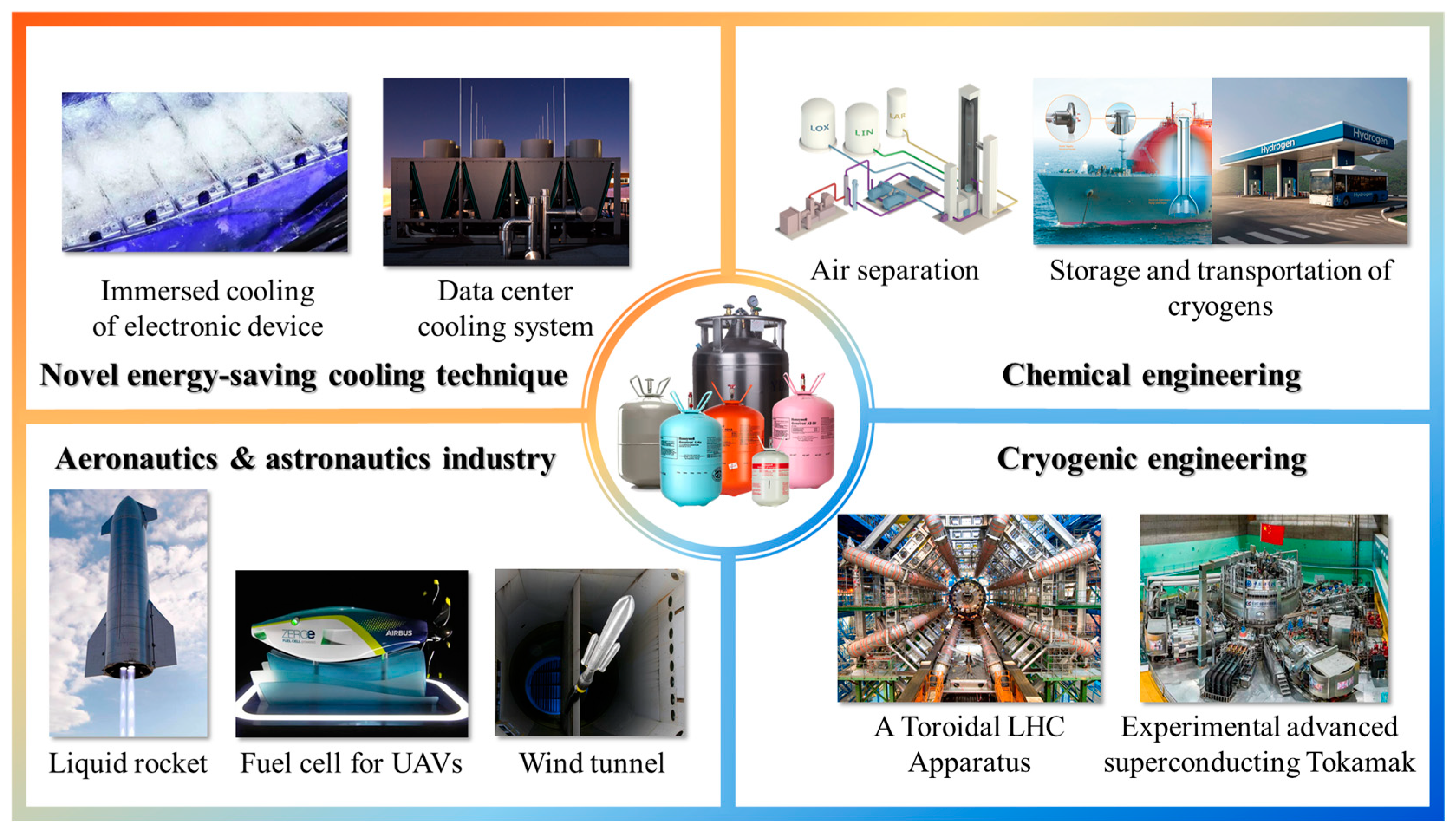
:1. Introduction
2. Applications Status of High-Speed Pumps
2.1. Cryogenic Liquid
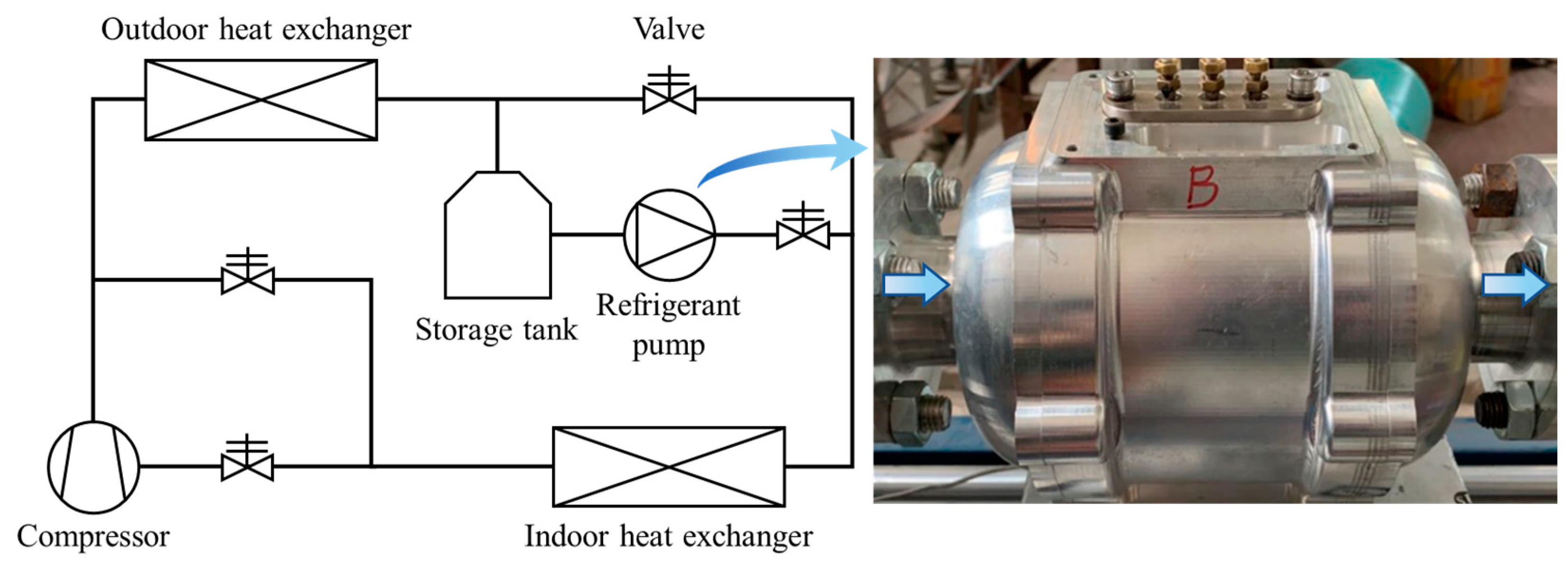
2.2. Liquid Refrigerant
3. Current Challenges
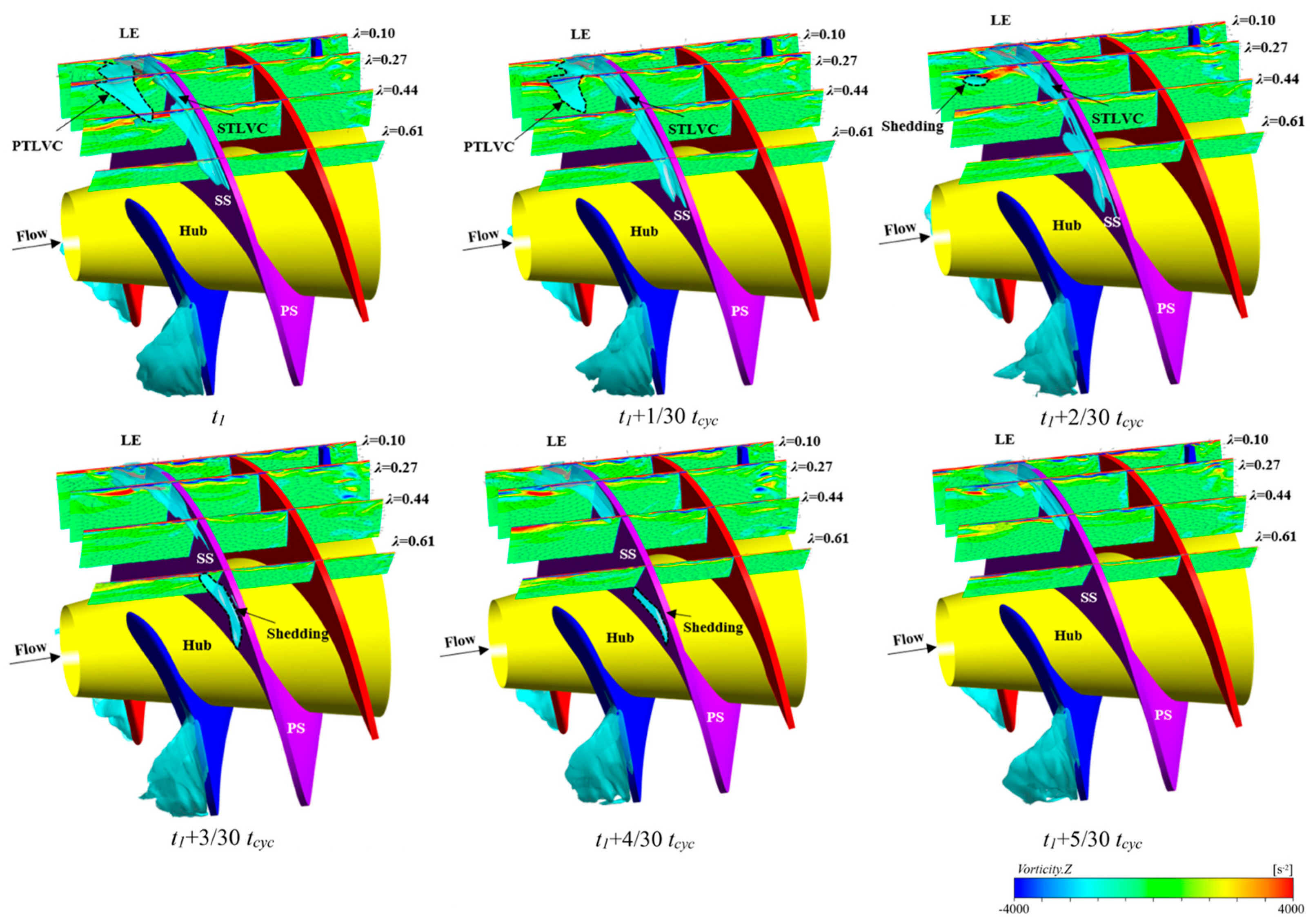
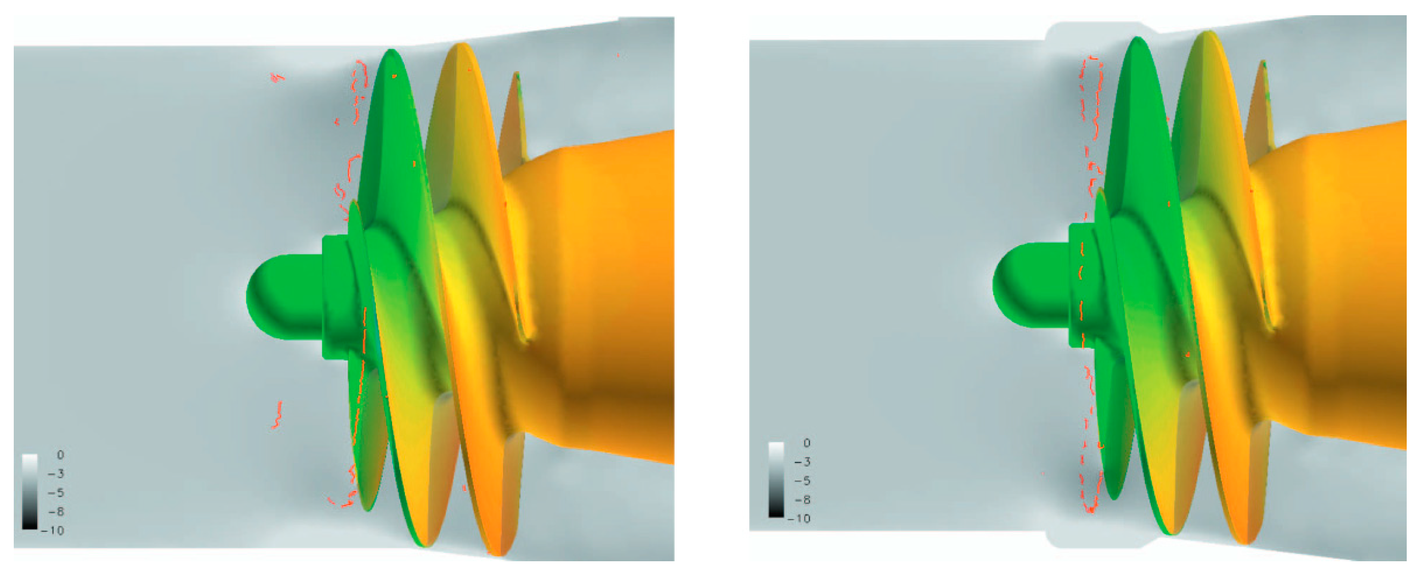
3.1. Cavitation in Inducer
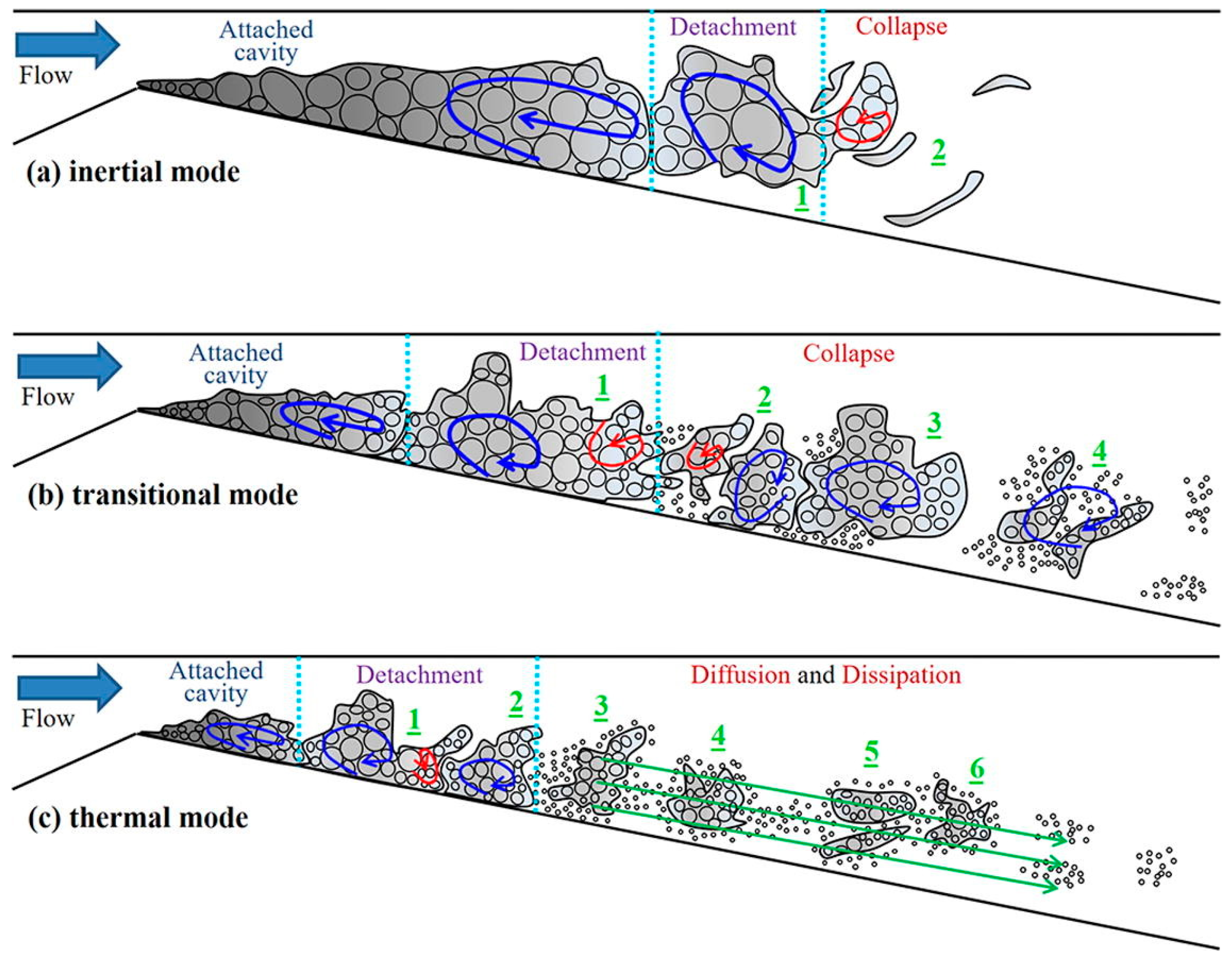
3.2. Thermal Effect
4. Prospects and Solutions
4.1. Development of a Low-Specific-Speed Centrifugal Pump with an Inducer
- Enhancing cavitation resistance: Incorporating an inducer at the pump inlet to enhance the NPSH, thereby mitigating the effects of high rotational speeds and complex operating conditions on pump performance. The design of the inducer should account for the impacts of cavitation dynamics and thermal effects.
- Optimizing impeller design: optimizing impeller profile design methods to improve hydraulic performance, addressing issues of high energy loss and low efficiency at ultra-low specific speeds.
- Flow-induced noise and vibrations: attention should be given to flow-induced noise and bearing vibrations during high-speed operation, as the performance of high-speed bearings directly influences the operational lifespan of the pump.
- Compact and maintenance-friendly design: the pump design should be more compact and easier to maintain, with efforts to reduce the weight and volume while also lowering manufacturing and operational maintenance costs.
4.2. Application of a Centrifugal Pump with Hydrodynamic Bearings
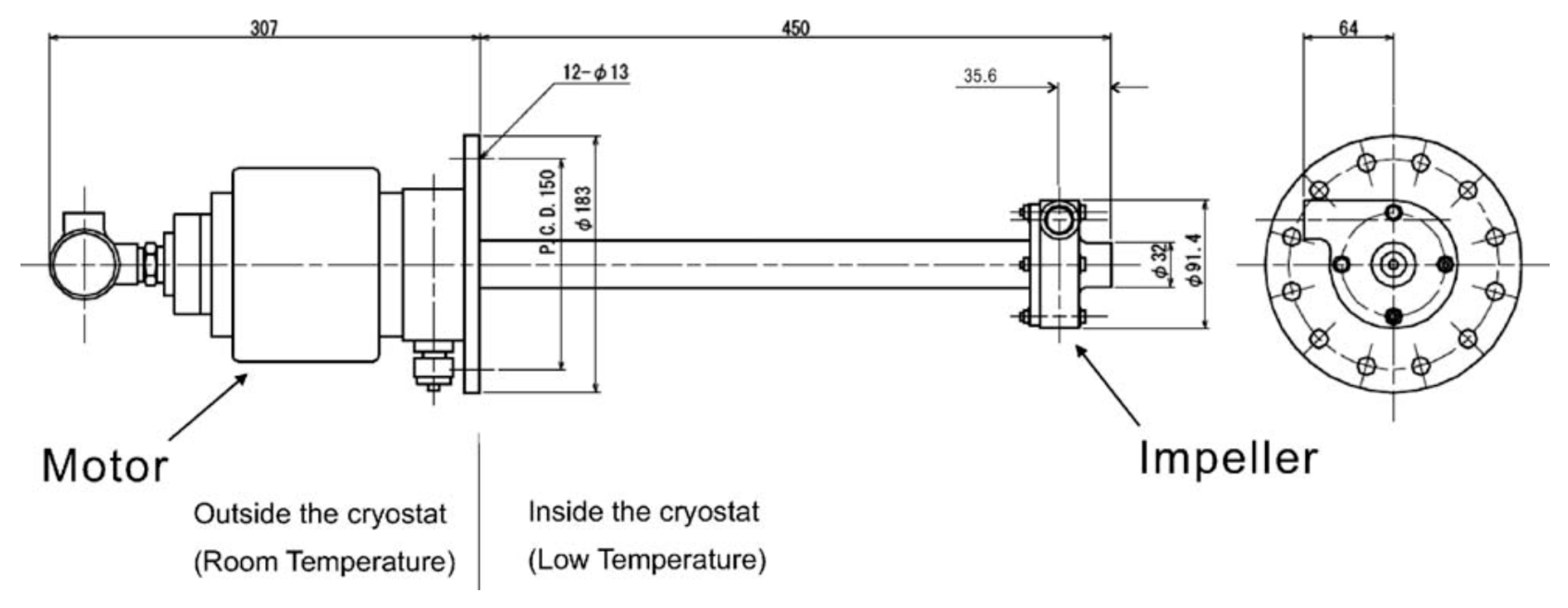
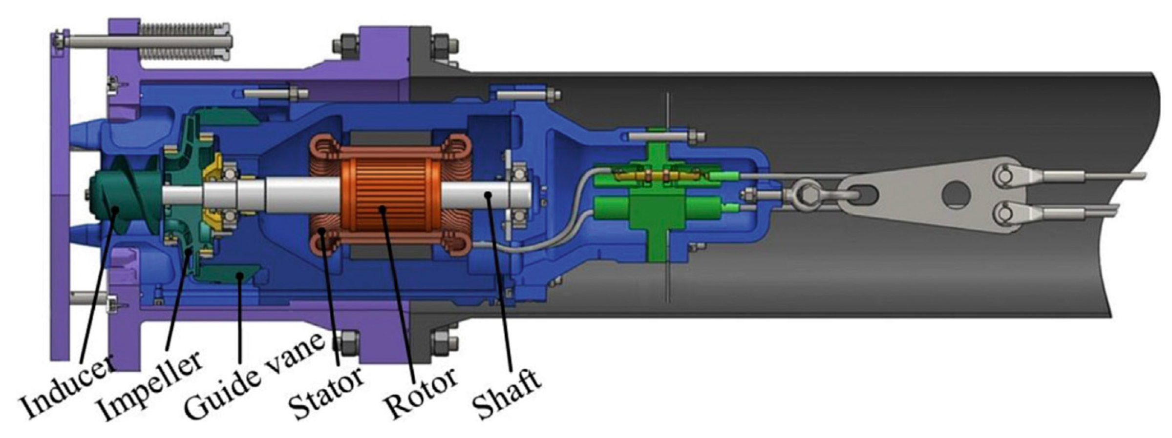
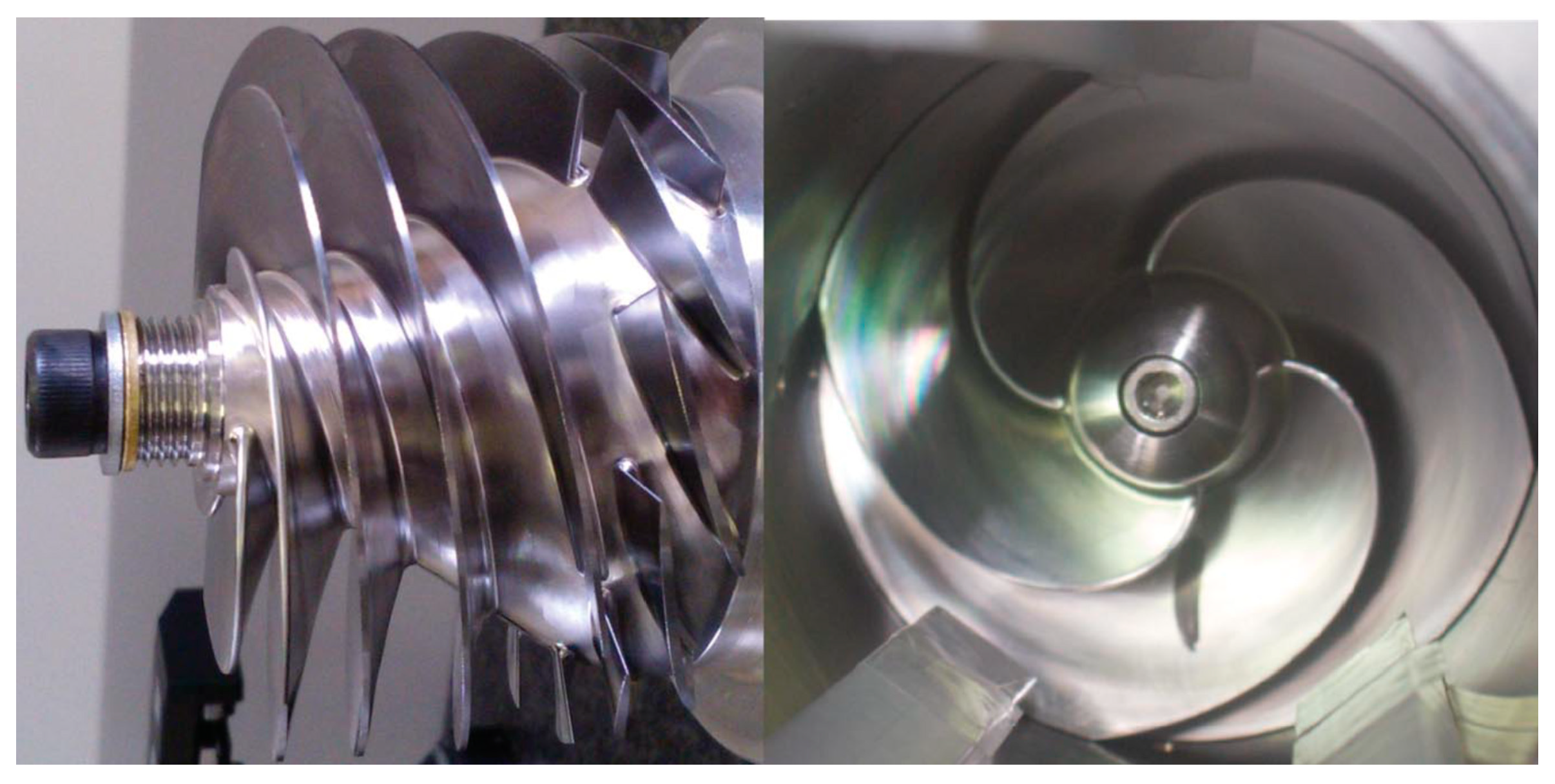
4.2.1. The Structural Design of the Prototype
4.2.2. Research Methods
4.2.3. Test Results of Prototype
5. Conclusions
- (1)
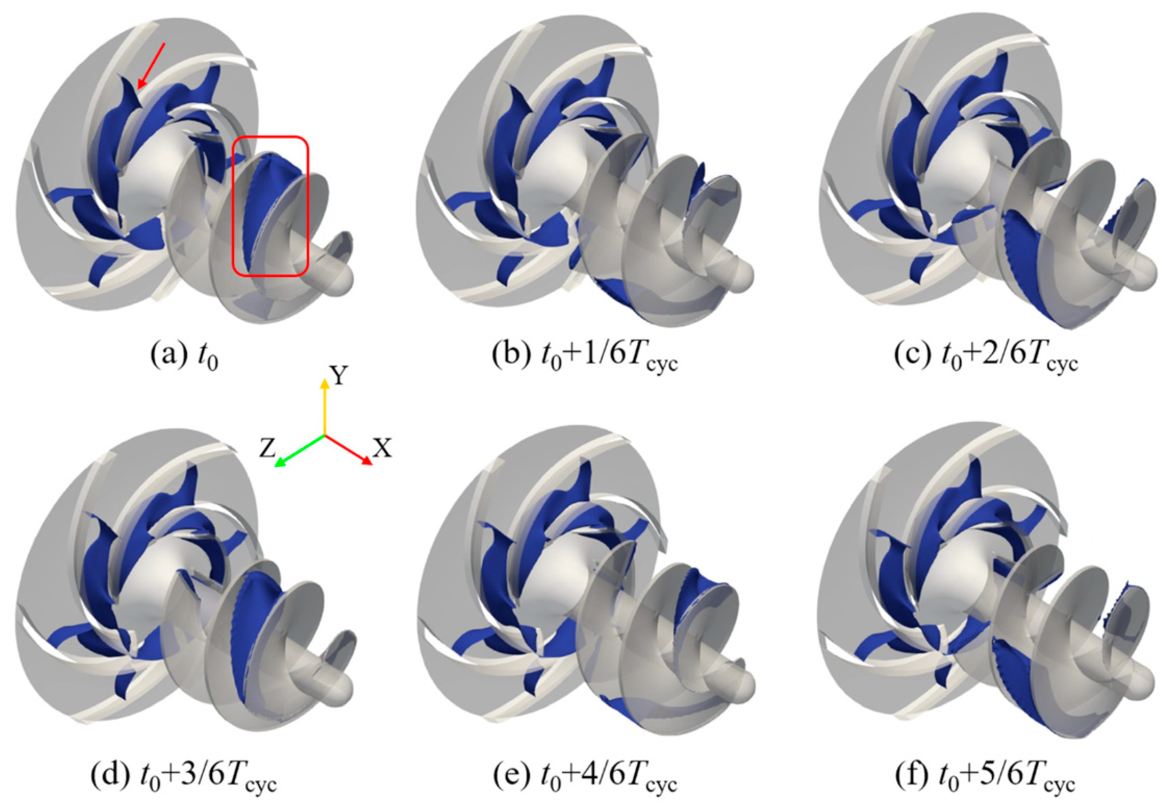
- Cavitation is the most common issue encountered in the pumping process of high-speed pumps. An inducer can enhance the cavitation resistance of pumps, significantly improving their hydraulic performance and stability. The accurate prediction of the cavitation intensity in an inducer using improved cavitation models is crucial for the effective design and performance optimization of high-speed pumps.
- (2)
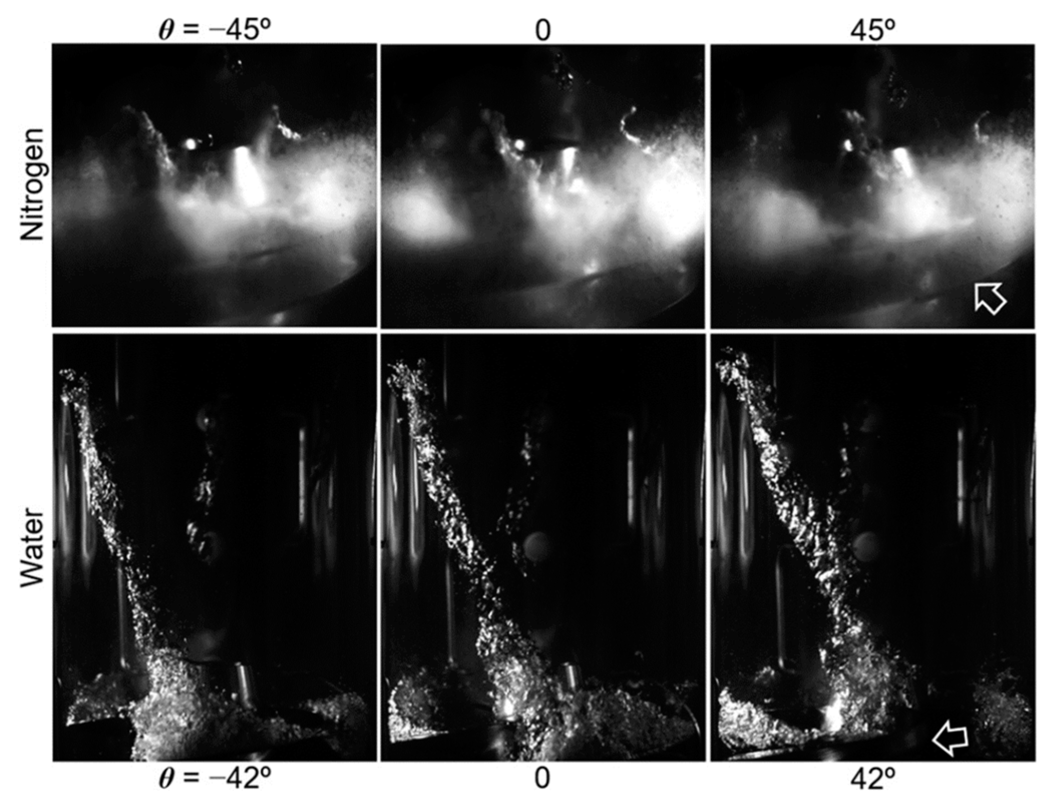
- Compared to cavitation studies with room-temperature water, cavitation experiments with low-temperature thermosensitive fluids are relatively few due to the complexity and difficulty of setting up the testing systems. Capturing cavity flow behavior through high-speed photography has become one of the important research methods for exploring cavitation characteristics and mechanisms. However, limited by current technological conditions, conducting cryogenic cavitation flow experiments in inducers is extremely challenging.
- (3)
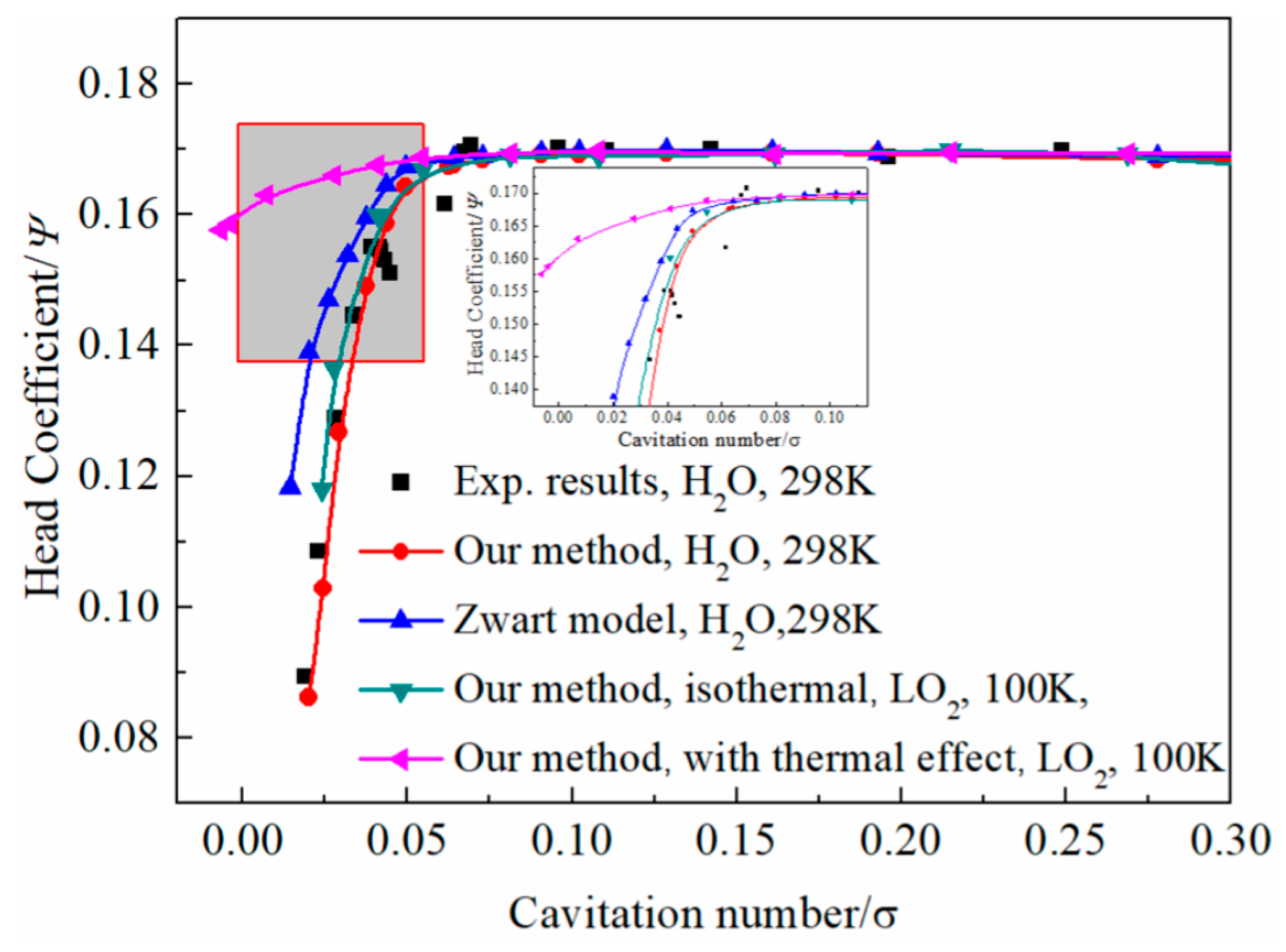
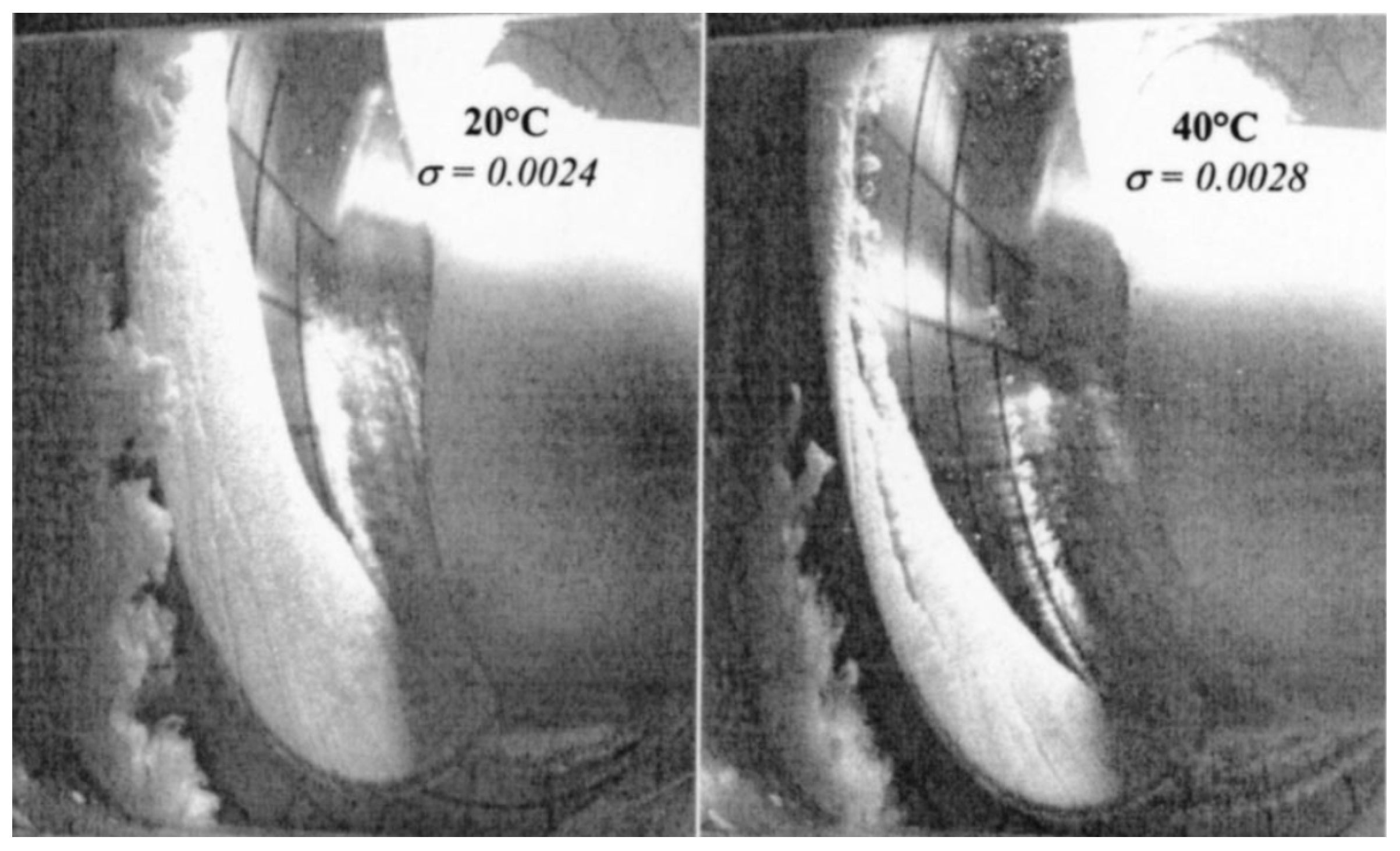
- Thermal effects have become the focus of research on cavitation dynamics of thermosensitive fluids. The local temperature drop caused by thermal effects suppresses the growth and collapse of cavities. Affected by the thermal effects, the cavitating flow characteristics in hydraulic components such as hydrofoils, Venturi tubes, and inducers have been extensively studied and demonstrated.
- (4)
- A two-stage high-speed refrigerant pump with an inducer and hydrodynamic bearings is proposed. Under design conditions (n = 7000 rpm, Q = 1.5 m3/h), the pump achieves a head of 56.5 m with an efficiency of 36.1%. The stability and reliability of the prototype have been thoroughly validated, indicating significant application potential in data center cooling systems and novel electronic device cooling technologies.
Author Contributions
Funding
Conflicts of Interest
References
- Lobanoff, V.S.; Ross, R. Centrifugal Pumps: Design and Application; Elsevier: Amsterdam, The Netherlands, 1985. [Google Scholar]
- Shah, S.R.; Jain, S.V.; Patel, R.N.; Lakhera, V.J. CFD for Centrifugal Pumps: A Review of the State-of-the-Art. Procedia Eng. 2013, 51, 715–720. [Google Scholar] [CrossRef]
- Stosiak, M.; Karpenko, M.; Prentkovskis, O.; Deptuła, A.; Skačkauskas, P. Research of Vibrations Effect on Hydraulic Valves in Military Vehicles. Def. Technol. 2023, 30, 111–125. [Google Scholar] [CrossRef]
- Choi, J.H.; Kim, N.-H.; Kogiso, N. Reliability for Aerospace Systems: Methods and Applications. Adv. Mech. Eng. 2016, 8, 168781401667709. [Google Scholar] [CrossRef]
- Gülich, J.F. Centrifugal Pumps; Springer International Publishing: Cham, Switzerland, 2020; ISBN 978-3-030-14787-7. [Google Scholar]
- Li, W.; Yang, Q.; Yang, Y.; Ji, L.; Shi, W.; Agarwal, R. Optimization of Pump Transient Energy Characteristics Based on Response Surface Optimization Model and Computational Fluid Dynamics. Appl. Energy 2024, 362, 123038. [Google Scholar] [CrossRef]
- Li, Y.; Liu, D.; Cui, B.; Lin, Z.; Zheng, Y.; Ishnazarov, O. Studying Particle Transport Characteristics in Centrifugal Pumps under External Vibration Using CFD-DEM Simulation. Ocean Eng. 2024, 301, 117538. [Google Scholar] [CrossRef]
- Rorro, F.; Fiusco, F.; Broman, L.M.; Prahl Wittberg, L. Backflow at the Inlet of Centrifugal Blood Pumps Enhanced by Geometrical Features. Phys. Fluids 2024, 36, 037127. [Google Scholar] [CrossRef]
- Zhang, Y.-L.; Li, W. A Precisive Calculation Method of Volumetric and Hydraulic Efficiency of Centrifugal Pumps. Phys. Fluids 2023, 35, 077104. [Google Scholar] [CrossRef]
- Lin, X.; Zhang, B.; Zhang, M.; Zhao, Y.; Lai, T.; Chen, L.; Xue, R. Influence of Internal Flow on the Performance of High-Speed Centrifugal Pumps with a Fully Sealed Structure. Appl. Sci. 2022, 12, 5263. [Google Scholar] [CrossRef]
- Tani, N.; Yamanishi, N.; Tsujimoto, Y. Influence of Flow Coefficient and Flow Structure on Rotational Cavitation in Inducer. J. Fluids Eng. 2012, 134, 021302. [Google Scholar] [CrossRef]
- Xue, R.; Lin, X.; Zhang, B.; Zhou, H.; Lai, T.; Hou, Y. CFD and Energy Loss Model Analysis of High-Speed Centrifugal Pump with Low Specific Speed. Appl. Sci. 2022, 12, 7435. [Google Scholar] [CrossRef]
- Čdina, M. Detection of cavitation phenomenon in a centrifugal pump using audible sound. Mech. Syst. Signal Process. 2003, 17, 1335–1347. [Google Scholar] [CrossRef]
- Langthjem, M.A.; Olhoff, N. A Numerical Study of Flow-Induced Noise in a Two-Dimensional Centrifugal Pump. Part II. Hydroacoustics. J. Fluids Struct. 2004, 19, 369–386. [Google Scholar] [CrossRef]
- Stosiak, M.; Karpenko, M. Dynamics of Machines and Hydraulic Systems: Mechanical Vibrations and Pressure Pulsations; Synthesis Lectures on Mechanical Engineering; Springer Nature: Cham, Switzerland, 2024; ISBN 978-3-031-55524-4. [Google Scholar]
- Wei, A.; Yu, L.; Qiu, L.; Zhang, X. Cavitation in Cryogenic Fluids: A Critical Research Review. Phys. Fluids 2022, 34, 101303. [Google Scholar] [CrossRef]
- Ge, M.; Petkovšek, M.; Zhang, G.; Jacobs, D.; Coutier-Delgosha, O. Cavitation Dynamics and Thermodynamic Effects at Elevated Temperatures in a Small Venturi Channel. Int. J. Heat Mass Transf. 2021, 170, 120970. [Google Scholar] [CrossRef]
- Franc, J.-P.; Rebattet, C.; Coulon, A. An Experimental Investigation of Thermal Effects in a Cavitating Inducer. J. Fluids Eng. 2004, 126, 716–723. [Google Scholar] [CrossRef]
- Pengo, R.; Junker, S.; Ten Kate, H.H.J. Liquid Helium Centrifugal Pump Characteristics from 80 g/s to 1200 g/s. Cryogenics 2010, 50, 8–12. [Google Scholar] [CrossRef]
- Mihara, S.; Haruyama, T.; Iwamoto, T.; Uchiyama, Y.; Ootani, W.; Kasami, K.; Sawada, R.; Terasawa, K.; Doke, T.; Natori, H.; et al. Development of a Method for Liquid Xenon Purification Using a Cryogenic Centrifugal Pump. Cryogenics 2006, 46, 688–693. [Google Scholar] [CrossRef]
- Haruyama, T.; Mito, T.; Yamamoto, A.; Doi, Y.; Matsumoto, K.; Kajiwara, H. Performance of a Liquid Helium Centrifugal Pump for the TOPAZ Superconducting Magnet. Cryogenics 1988, 28, 157–160. [Google Scholar] [CrossRef]
- Ludtke, P.R.; Daney, D.E. Cavitation Characteristics of a Small Centrifugal Pump in He I and He II. Cryogenics 1988, 28, 96–100. [Google Scholar] [CrossRef]
- Steward, W.G. Centrifugal Pump for Superfluid Helium. Cryogenics 1986, 26, 97–102. [Google Scholar] [CrossRef]
- Li, G.; Caldwell, S.; Clark, J.A.; Gulick, S.; Hecht, A.; Lascar, D.D.; Levand, T.; Morgan, G.; Orford, R.; Savard, G.; et al. A Compact Cryogenic Pump. Cryogenics 2016, 75, 35–37. [Google Scholar] [CrossRef]
- Vaghela, H.; Banerjee, J.; Naik, H.; Sarkar, B. Cryogenic Pump at 4 K Temperature Level -Basic Hydro-Dynamic Design Approach. Indian J. Cryog. 2012, 37, 134–139. [Google Scholar]
- Hou, H.; Zhang, Y.; Li, Z.; Jiang, T.; Zhang, J.; Xu, C. Numerical Analysis of Entropy Production on a LNG Cryogenic Submerged Pump. J. Nat. Gas Sci. Eng. 2016, 36, 87–96. [Google Scholar] [CrossRef]
- Li, W.; Li, S.; Ji, L.; Zhao, X.; Shi, W.; Agarwal, R.K.; Awais, M.; Yang, Y. A Study on the Cavitation and Pressure Pulsation Characteristics in the Impeller of an LNG Submerged Pump. Machines 2021, 10, 14. [Google Scholar] [CrossRef]
- Son, Y.-J.; Kim, Y.-I.; Yang, H.-M.; Lee, K.-Y.; Suh, J.-W.; Yoon, J.Y.; Choi, Y.-S. Influence of Cavitation on Inducer and Return Channels of LNG Pump. J. Mech. Sci. Technol. 2024, 38, 259–270. [Google Scholar] [CrossRef]
- Wang, C.; Zhang, Y.; Hou, H.; Zhang, J.; Xu, C. Entropy Production Diagnostic Analysis of Energy Consumption for Cavitation Flow in a Two-Stage LNG Cryogenic Submerged Pump. Int. J. Heat Mass Transf. 2019, 129, 342–356. [Google Scholar] [CrossRef]
- Zhang, J.; Xu, C.; Zhang, Y.; Zhou, X. Quasi-3D Hydraulic Design in the Application of an LNG Cryogenic Submerged Pump. J. Nat. Gas Sci. Eng. 2016, 29, 89–100. [Google Scholar] [CrossRef]
- Brailovskii, Y.L. High-Pressure Pumps for Cryogenic Liquids: Problems and Prospects. Chem. Pet. Eng. 2000, 36, 90–93. [Google Scholar] [CrossRef]
- Zhang, W.; Gao, R.; Cheng, J.; Chen, W.; Song, Y.; Liao, D. A Review on the Precise Control of the Liquid Nitrogen Supplying System in Transonic Cryogenic Wind Tunnel. J. Therm. Sci. 2023, 32, 692–707. [Google Scholar] [CrossRef]
- Xue, R.; Chen, L.; Zhong, X.; Liu, X.; Chen, S.; Hou, Y. Unsteady Cavitation of Liquid Nitrogen Flow in Spray Nozzles under Fluctuating Conditions. Cryogenics 2019, 97, 144–148. [Google Scholar] [CrossRef]
- Shao, X.; Zhao, W. Liquid Hydrogen Centrifugal Pump Optimization Based on Reducing Hydraulic Loss and Improving Cavitation. Int. J. Hydrogen Energy 2024, 49, 1419–1431. [Google Scholar] [CrossRef]
- Barske, U.M. Development of Some Unconventional Centrifugal Pumps. Proc. Inst. Mech. Eng. 1960, 174, 437–461. [Google Scholar] [CrossRef]
- Watanabe, D.; Manako, H.; Onga, T.; Tamura, T.; Ikeda, K.; Isono, M. Combustion Stability Improvement of LE-9 Engine for Booster Stage of H3 Launch Vehicle. Mitsubishi Heavy Ind. Tech. Rev. 2016, 53, 28–35. [Google Scholar]
- Wang, C.; Xiang, L.; Tan, Y.; Chen, H.; Xu, K. Experimental Investigation of Thermal Effect on Cavitation Characteristics in a Liquid Rocket Engine Turbopump Inducer. Chin. J. Aeronaut. 2021, 34, 48–57. [Google Scholar] [CrossRef]
- Jiang, J.; Li, Y.; Pei, C.; Li, L.; Fu, Y.; Cheng, H.; Sun, Q. Cavitation Performance of High-Speed Centrifugal Pump with Annular Jet and Inducer at Different Temperatures and Void Fractions. J. Hydrodyn. 2019, 31, 93–101. [Google Scholar] [CrossRef]
- Negishi, H.; Ohno, S.; Ogawa, Y.; Aoki, K.; Kobayashi, T.; Okita, K.; Mizuno, T. Numerical Analysis of Unshrouded Impeller Flowfield in the LE-X Liquid Hydrogen Pump. In Proceedings of the 53rd AIAA/SAE/ASEE Joint Propulsion Conference (American Institute of Aeronautics and Astronautics), Atlanta, GA, USA, 10–12 July 2017. [Google Scholar]
- Lettieri, C.; Spakovszky, Z.; Jackson, D.; Schwille, J. Characterization of Cavitation Instabilities in a Four-Bladed Turbopump Inducer. J. Propuls. Power 2018, 34, 510–520. [Google Scholar] [CrossRef]
- Gong, Y.; Zhou, F.; Ma, G.; Liu, S. Advancements on Mechanically Driven Two-Phase Cooling Loop Systems for Data Center Free Cooling. Int. J. Refrig. 2022, 138, 84–96. [Google Scholar] [CrossRef]
- Tian, G.; Zhao, C.; Zheng, H.; Fan, X. Experimental Study on the Operating Characteristics of Refrigerant Pumps for Solar Ejector Refrigeration Systems. Sol. Energy 2022, 239, 50–58. [Google Scholar] [CrossRef]
- Zhang, S.; Ma, G.; Zhou, F. Experimental Study on a Pump Driven Loop-Heat Pipe for Data Center Cooling. J. Energy Eng. 2015, 141, 04014054. [Google Scholar] [CrossRef]
- Lin, Y.; Liu, J.; Xu, X.; Liu, Z.; Li, G. Experimental research on air conditioning system of a computer room based on refrigerant pump pressurization. J. Refrig. 2020, 41, 83–88. (In Chinese) [Google Scholar]
- Sun, Y.; Wang, T.; Yang, L.; Hu, L.; Zeng, X. Research of an Integrated Cooling System Consisted of Compression Refrigeration and Pump-Driven Heat Pipe for Data Centers. Energy Build. 2019, 187, 16–23. [Google Scholar] [CrossRef]
- Fang, X.; Zhang, B.; Lin, X.; Zhou, H.; Chen, S.; Hou, Y.; Xue, R.; Zhang, Z. Numerical and Experimental Investigation of Flow Characteristics in a Fluid Self-Lubricating Centrifugal Pump with R134a Refrigerant. Appl. Sci. 2023, 13, 8062. [Google Scholar] [CrossRef]
- Franc, J.-P.; Michel, J.-M. Fundamentals of Cavitation; Fluid Mechanics and Its Applications; Springer: Dordrecht, The Netherlands, 2005; Volume 76, ISBN 978-1-4020-2232-6. [Google Scholar]
- Ito, Y.; Zheng, X.; Nagasaki, T. One-Way Coupling Numerical Simulation of Cryogenic Cavitation Around an Inducer. Int. J. Fluid Mach. Syst. 2019, 12, 235–243. [Google Scholar] [CrossRef]
- Chen, T.; Mu, Z.; Chen, J.; Tan, S.; Fan, Y. Numerical Investigations on the Mechanisms of the Tip Leakage Vortex Cavitation Development in a Cryogenic Inducer with Large Eddy Simulation. Phys. Fluids 2023, 35, 073328. [Google Scholar] [CrossRef]
- Zhang, Y.; Ren, X.; Wang, Y.; Li, X.; Ito, Y.; Gu, C. Investigation of the Cavitation Model in an Inducer for Water and Liquid Nitrogen. Proc. Inst. Mech. Eng. Part C J. Mech. Eng. Sci. 2019, 233, 6939–6952. [Google Scholar] [CrossRef]
- Ito, Y. The World’s First Test Facility That Enables the Experimental Visualization of Cavitation on a Rotating Inducer in Both Cryogenic and Ordinary Fluids. J. Fluids Eng. 2021, 143, 121105. [Google Scholar] [CrossRef]
- Gopalakrishnan, K.; Prentkovskis, O.; Jackiva, I.; Junevičius, R. (Eds.) TRANSBALTICA XI: Transportation Science and Technology: Proceedings of the International Conference TRANSBALTICA, Vilnius, Lithuania, 2–3 May 2019; Lecture Notes in Intelligent Transportation and Infrastructure; Springer International Publishing: Cham, Switzerland, 2020; ISBN 978-3-030-38665-8. [Google Scholar]
- Shao, X.; Zhao, W. Performance Study on a Partial Emission Cryogenic Circulation Pump with High Head and Small Flow in Various Conditions. Int. J. Hydrogen Energy 2019, 44, 27141–27150. [Google Scholar] [CrossRef]
- Kim, D.-J.; Sung, H.J.; Choi, C.-H.; Kim, J.-S. Cavitation Instabilities of an Inducer in a Cryogenic Pump. Acta Astronaut. 2017, 132, 19–24. [Google Scholar] [CrossRef]
- Kim, D.-J.; Sung, H.J.; Choi, C.-H.; Kim, J.-S. Cavitation Instabilities During the Development Testing of a Liquid Oxygen Pump. J. Propuls. Power 2017, 33, 187–192. [Google Scholar] [CrossRef]
- Shimura, T.; Shimagaki, M.; Watanabe, Y.; Watanabe, M.; Hasegawa, S.; Takata, S. Cavitation induced v ibration of le-7a oxygen turbopump. In Proceedings of the Fifth International Symposium on Cavitation (CAV2003), Osaka, Japan, 1–4 November 2003. [Google Scholar]
- Kimura, T.; Yoshida, Y.; Hashimoto, T.; Shimagaki, M. Numerical Simulation for Vortex Structure in a Turbopump Inducer: Close Relationship With Appearance of Cavitation Instabilities. J. Fluids Eng. 2008, 130, 051104. [Google Scholar] [CrossRef]
- Karakas, E.S.; Watanabe, H.; Aureli, M.; Evrensel, C.A. Cavitation Performance of Constant and Variable Pitch Helical Inducers for Centrifugal Pumps: Effect of Inducer Tip Clearance. J. Fluids Eng. 2020, 142, 021211. [Google Scholar] [CrossRef]
- Ge, M.; Zhang, G.; Petkovšek, M.; Long, K.; Coutier-Delgosha, O. Intensity and Regimes Changing of Hydrodynamic Cavitation Considering Temperature Effects. J. Clean. Prod. 2022, 338, 130470. [Google Scholar] [CrossRef]
- Ge, M.; Sun, C.; Zhang, G.; Coutier-Delgosha, O.; Fan, D. Combined Suppression Effects on Hydrodynamic Cavitation Performance in Venturi-Type Reactor for Process Intensification. Ultrason. Sonochemistry 2022, 86, 106035. [Google Scholar] [CrossRef] [PubMed]
- Hord, J. Cavitation in Liquid Cryogens. 3: Ogives; NASA: Washington, DC, USA, 1973.
- Hord, J. Cavitation in Liquid Cryogens. 4: Combined Correlations for Venturi, Hydrofoil, Ogives, and Pumps; NASA: Washington, DC, USA, 1974.
- Ge, M.; Manikkam, P.; Ghossein, J.; Kumar Subramanian, R.; Coutier-Delgosha, O.; Zhang, G. Dynamic Mode Decomposition to Classify Cavitating Flow Regimes Induced by Thermodynamic Effects. Energy 2022, 254, 124426. [Google Scholar] [CrossRef]
- Chen, T.; Huang, B.; Wang, G.; Zhang, H.; Wang, Y. Numerical Investigation of Thermo-Sensitive Cavitating Flows in a Wide Range of Free-Stream Temperatures and Velocities in Fluoroketone. Int. J. Heat Mass Transf. 2017, 112, 125–136. [Google Scholar] [CrossRef]
- Zhang, B.; Zhang, Z.; Fang, X.; Xue, R.; Chen, S.; Hou, Y. Data-Driven Modal Decomposition of R134a Refrigerant Cavitating Flow in Venturi Tube. Phys. Fluids 2024, 36, 034124. [Google Scholar] [CrossRef]
- Chen, T.; Wang, G.; Huang, B.; Wang, K. Numerical Study of Thermodynamic Effects on Liquid Nitrogen Cavitating Flows. Cryogenics 2015, 70, 21–27. [Google Scholar] [CrossRef]
- Long, X.; Liu, Q.; Ji, B.; Lu, Y. Numerical Investigation of Two Typical Cavitation Shedding Dynamics Flow in Liquid Hydrogen with Thermodynamic Effects. Int. J. Heat Mass Transf. 2017, 109, 879–893. [Google Scholar] [CrossRef]
- Chen, T.; Chen, H.; Liang, W.; Huang, B.; Xiang, L. Experimental Investigation of Liquid Nitrogen Cavitating Flows in Converging-Diverging Nozzle with Special Emphasis on Thermal Transition. Int. J. Heat Mass Transf. 2019, 132, 618–630. [Google Scholar] [CrossRef]
- Chen, T.; Chen, H.; Liu, W.; Huang, B.; Wang, G. Unsteady Characteristics of Liquid Nitrogen Cavitating Flows in Different Thermal Cavitation Mode. Appl. Therm. Eng. 2019, 156, 63–76. [Google Scholar] [CrossRef]
- Zhu, J.; Xie, H.; Feng, K.; Zhang, X.; Si, M. Unsteady Cavitation Characteristics of Liquid Nitrogen Flows through Venturi Tube. Int. J. Heat Mass Transf. 2017, 112, 544–552. [Google Scholar] [CrossRef]
- Zhu, J.; Wang, S.; Zhang, X. Influences of Thermal Effects on Cavitation Dynamics in Liquid Nitrogen through Venturi Tube. Phys. Fluids 2020, 32, 012105. [Google Scholar] [CrossRef]
- Murakami, M.; Harada, K. Experimental Study of Thermo-Fluid Dynamic Effect in He II Cavitating Flow. Cryogenics 2012, 52, 620–628. [Google Scholar] [CrossRef]
- Niiyama, K.; Hasegawa, S.; Tsuda, S.; Yoshida, Y.; Tamura, T.; Oike, M. Thermodynamic Effects on Cryogenic Cavitating Flow in an Orifice. In Proceedings of the 7th International Symposium on Cavitation (CAV2009), Ann Arbor, MI, USA, 17–22 August 2009. [Google Scholar]
- Liang, W.; Chen, T.; Huang, B.; Wang, G. Thermodynamic Analysis of Unsteady Cavitation Dynamics in Liquid Hydrogen. Int. J. Heat Mass Transf. 2019, 142, 118470. [Google Scholar] [CrossRef]
- Yoshida, Y.; Eguchi, M.; Motomura, T.; Uchiumi, M.; Kure, H.; Maruta, Y. Rotordynamic Forces Acting on Three-Bladed Inducer Under Supersynchronous/Synchronous Rotating Cavitation. J. Fluids Eng. 2010, 132, 061105. [Google Scholar] [CrossRef]
- Yoshida, Y.; Kikuta, K.; Hasegawa, S.; Shimagaki, M.; Tokumasu, T. Thermodynamic Effect on a Cavitating Inducer in Liquid Nitrogen. J. Fluids Eng. 2006, 129, 273–278. [Google Scholar] [CrossRef]
- Ikohagi, T. Influence of Thermodynamic Effect on Synchronous Rotating Cavitation. J. Fluids Eng. 2007, 129, 871–876. [Google Scholar]
- Ito, Y.; Tsunoda, A.; Kurishita, Y.; Kitano, S.; Nagasaki, T. Experimental Visualization of Cryogenic Backflow Vortex Cavitation with Thermodynamic Effects. J. Propuls. Power 2016, 32, 71–82. [Google Scholar] [CrossRef]
- Fan, Y.; Chen, T.; Liang, W.; Wang, G.; Huang, B. Numerical and Theoretical Investigations of the Cavitation Performance and Instability for the Cryogenic Inducer. Renew. Energy 2022, 184, 291–305. [Google Scholar] [CrossRef]
- Chen, Z.; Yang, S.; Li, X.; Li, Y.; Li, L. Investigation on Leakage Vortex Cavitation and Corresponding Enstrophy Characteristics in a Liquid Nitrogen Inducer. Cryogenics 2023, 129, 103606. [Google Scholar] [CrossRef]
- Wei, A.; Wang, W.; Hu, Y.; Feng, S.; Qiu, L.; Zhang, X. Numerical and Experimental Analysis of the Cavitation and Flow Characteristics in Liquid Nitrogen Submersible Pump. Phys. Fluids 2024, 36, 042109. [Google Scholar] [CrossRef]
- Blumenthal, R.F.; Kelecy, F.J. Numerical Predictions of Cavitating Flow Within a Liquid Hydrogen Inducer. In Proceedings of the ASME Turbo Expo 2021: Turbomachinery Technical Conference and Exposition. Volume 2C: Turbomachinery—Design Methods and CFD Modeling for Turbomachinery; Ducts, Noise, and Component Interactions, Virtual, Online, 7–11 June 2021. [Google Scholar]
- Challier, G. Thermodynamic Effect on a Cavitating Inducer in Liquid Hydrogen. J. Fluids Eng. 2010, 132, 111305. [Google Scholar]
- Xiang, L.; Tan, Y.; Chen, H.; Xu, K. Numerical Simulation of Cryogenic Cavitating Flow in LRE Oxygen Turbopump Inducer. Cryogenics 2022, 126, 103540. [Google Scholar] [CrossRef]
- Shi, G.; Wei, Y.; Liu, S. Cavitation Flow Characteristics of Water and Liquid Oxygen in the Inducer Considering Thermodynamic Effect. Energies 2022, 15, 4943. [Google Scholar] [CrossRef]
- Holl, J.W.; Billet, M.L.; Weir, D.S. Thermodynamic Effects on Developed Cavitation. J. Fluids Eng. 1975, 97, 507–513. [Google Scholar] [CrossRef]
- Franc, J.-P.; Pellone, C. Analysis of Thermal Effects in a Cavitating Inducer Using Rayleigh Equation. J. Fluids Eng. 2007, 129, 974–983. [Google Scholar] [CrossRef]
- Ren, T. Study on the High Speed Motorized Centrifugal Air Compressor with Water Lubricated Journal Bearing. Ph.D. Thesis, University of Science and Technology Beijing, Beijing, China, 2017. (In Chinese). [Google Scholar]
- Wu, C. Investigation of Low-Specific-Speed Centrifugal Impeller Fluid-Induced Excitations and Its Control Methods. Ph.D. Thesis, Zhejiang University, Hangzhou, China, 2023. (In Chinese). [Google Scholar]


| Parameters | Water | LN2 | LH2 | R114 | R134a | R410A |
|---|---|---|---|---|---|---|
| T/K | 283 | 77 | 23 | 283 | 283 | 283 |
| 84 | 12,108 | 53,690 | 4700 | 13,980 | 32,500 | |
| 107,286.1 | 182.0 | 26.7 | 154.0 | 62.7 | 27.5 | |
| 2477.5 | 199.6 | 431.2 | 133.7 | 190.9 | / | |
| 578.4 | 145.5 | 103.4 | 64.3 | 87.7 | 97.5 | |
| 1311.7 | 162.9 | 11.0 | 325.8 | 235.3 | 143.0 |
| Design Parameter | Value | |
|---|---|---|
| Inducer | Number of blades | 3 |
| Inducer diameter/mm | 21.4 | |
| Hub diameter/mm | 12 | |
| Tip clearance/mm | 0.3 | |
| Primary impeller | Number of blades | 6 |
| Inlet diameter/mm | 22 | |
| Outlet blade angle/° | 28 | |
| Outlet width/mm | 3 | |
| Outlet diameter/mm | 52 | |
| Primary vaned diffuser | Number of blades | 8 |
| Outlet blade angle/° | 12 | |
| Outlet diameter/mm | 68 | |
| Secondary impeller | Number of blades | 6 |
| Inlet diameter/mm | 19 | |
| Outlet blade angle/° | 30 | |
| Outlet width/mm | 3 | |
| Outlet diameter/mm | 68 | |
| Secondary vaned diffuser | Number of blades | 8 |
| Outlet blade angle/° | 12 | |
| Outlet diameter/mm | 88 | |
| Discharge volute | Inlet width/mm | 3.6 |
| Discharge diameter/mm | 18 | |
Disclaimer/Publisher’s Note: The statements, opinions and data contained in all publications are solely those of the individual author(s) and contributor(s) and not of MDPI and/or the editor(s). MDPI and/or the editor(s) disclaim responsibility for any injury to people or property resulting from any ideas, methods, instructions or products referred to in the content. |
© 2024 by the authors. Licensee MDPI, Basel, Switzerland. This article is an open access article distributed under the terms and conditions of the Creative Commons Attribution (CC BY) license (https://creativecommons.org/licenses/by/4.0/).
Share and Cite
Zhang, B.; Niu, B.; Zhang, Z.; Chen, S.; Xue, R.; Hou, Y. Application and Challenge of High-Speed Pumps with Low-Temperature Thermosensitive Fluids. Energies 2024, 17, 3732. https://doi.org/10.3390/en17153732
Zhang B, Niu B, Zhang Z, Chen S, Xue R, Hou Y. Application and Challenge of High-Speed Pumps with Low-Temperature Thermosensitive Fluids. Energies. 2024; 17(15):3732. https://doi.org/10.3390/en17153732
Chicago/Turabian StyleZhang, Beile, Ben Niu, Ze Zhang, Shuangtao Chen, Rong Xue, and Yu Hou. 2024. "Application and Challenge of High-Speed Pumps with Low-Temperature Thermosensitive Fluids" Energies 17, no. 15: 3732. https://doi.org/10.3390/en17153732