Article

A Coupled Model of Multiscaled Creep Deformation and Gas Flow for Predicting Gas Depletion Characteristics of Shale Reservoir at the Field Scale

1
Key Laboratory of Ministry of Education on Safe Mining of Deep Metal Mines, School of Resources and Civil Engineering, Northeastern University, Shenyang 110004, China
2
Key Laboratory of Liaoning Province on Deep Engineering and Intelligent Technology, Northeastern University, Shenyang 110819, China
3
Hebei Research Center of the Basic Discipline Engineering Mechanics, Shijiazhuang Tiedao University, Shijiazhuang 050043, China
4
Department of Engineering Mechanics, Shijiazhuang Tiedao University, Shijiazhuang 050043, China
5
Institue of Geophysics, China Earthquake Administration, Beijing 100081, China
6
The National Joint Engineering Laboratory of Internet Applied Technology of Mines, China University of Mining & Technology (CUMT), Xuzhou 221116, China
*
Authors to whom correspondence should be addressed.
Energies 2024, 17(15), 3752; https://doi.org/10.3390/en17153752 (registering DOI)
Submission received: 15 June 2024 / Revised: 19 July 2024 / Accepted: 25 July 2024 / Published: 30 July 2024
(This article belongs to the Special Issue The Technology of Oil and Gas Production with Low Energy Consumption)

Abstract

:
The viscoelastic behavior of shale reservoirs indeed impacts permeability evolution and further gas flow characteristics, which have been experimentally and numerically investigated. However, its impact on the gas depletion profile at the field scale has seldom been addressed. To compensate for this deficiency, we propose a multiscaled viscoelasticity constitutive model, and furthermore, a full reservoir deformation–fluid flow coupled model is formed under the frame of the classical triple-porosity approach. In the proposed approach, a novel friction-based creep model comprising two distinct series of parameters is developed to generate the strain–time profiles for hydraulic fracture and natural fracture systems. Specifically, an equation considering the long-term deformation of hydraulic fracture, represented by the softness of Young’s modulus, is proposed to describe the conductivity evolution of hydraulic fractures. In addition, an effective strain permeability model is employed to replicate the permeability evolution of a natural fracture system considering viscoelasticity. The coupled model was implemented and solved within the framework of COMSOL Multiphysics (Version 5.4). The proposed model was first verified using a series of gas production data collected from the Barnett shale, resulting in good fitting results. Subsequently, a numerical analysis was conducted to investigate the impacts of the newly proposed parameters on the production process. The transient creep stage significantly affects the initial permeability, and its contribution to the permeability evolution remains invariable. Conversely, the second stage controls the long-term permeability evolution, with its dominant role increasing over time. Creep deformation lowers the gas flow rate, and hydraulic fracturing plays a predominant role in the early term, as the viscoelastic behavior of the natural fracture system substantially impacts the long-term gas flow rate. A higher in situ stress and greater formation depth result in significant creep deformation and, therefore, a lower gas flow rate. This work provides a new tool for estimating long-term gas flow rates at the field scale.

1. Introduction

With extensive exploration in North America and China, shale gas plays an irreplaceable role in the energy market. Indeterminacies are observed in its production capacity [1,2], with the gas flow rate exhibiting a dramatic decline in some gas fields. For example, in the Bakken shale formation, the rate decreased from 69% to 26% within the first three years [3]. After a considerable amount of research, several factors have been proposed to explain the rapid decrease in gas depletion profile: (i) inconsistency in flow ability between the seepage channel (nanotube) and gas storage unit (kerogen) [4]; (ii) decreasing conductivity during hydraulic fracturing because of the increased effective stress [5,6]; and (iii) reservoir consolidation due to fluid drainage [7,8,9]. The first two items have been extensively explored [10,11,12], and the last item—the impact of creep deformation—has been widely investigated at the sample scale. Conversely, its dominant role at the field scale has seldom been addressed.
Creep deformation, which defines time-dependent deformation under constant loading stress, has been widely characterized and can be subdivided into three sequential regimes [13,14]: transient (decelerating rate), secondary (constant rate), and tertiary (accelerating rate, leading to failure). The appearance of these three regimes depends on factors such as rock types, conditions of differential stress [15], pore fluid chemistry [16], confining stresses [17], temperature [18,19], and test duration [20]. Therefore, all three regimes may not appear for a given set of tests. After load application, primary or transient creep occurs, characterized by a decreasing strain rate; then, secondary or steady-state creep is determined by a constant rate load; and finally, if the steady-state strain rate is high, tertiary creep may develop, where the strain rate increases again and eventually leads to failure.
Several approaches have been proposed to describe the viscoelastic behavior of rocks: empirical models, micromechanism-based creep models, and component models [21,22]. The first approach employs mathematical functions such as power type, exponential type, and logarithmic type functions to fit experimental data. It is extensively applied because of its simple form and easy use [22,23]. However, the lack of a physical background limits its wide application. The micromechanism-based creep model, which considers damage accumulation at the fine and microscale, can assess the mechanical response and progressive evolution of the microstructure in rocks. Component models treat the stress–strain relationship as combining several standard mechanical elements, including Hooke springs, frictional elements, and Newton dashpots [17,24,25]. These models are extensively adopted due to their rigorous derivation process. However, the element that controls both elasticity and viscosity behaviors is still insufficient. Recently, the fractional element has become a popular approach for describing the stress–strain relationship [26,27] since the pioneering work of Scott Blair [28]. The fractional element-based creep model has attracted much attention because (i) the friction order can be determined to value the indicator of viscoelasticity, and (ii) it can be used to fit nonlinear creep deformation.
The creep behavior of shale gas is widely characterized as follows: (i) the drainage process takes a significantly long time, the internal structure of shale is expected to rearrange due to constant compaction from adjacent rocks, and as a result, the porosity and permeability of shale vary [7,29]; and (ii) unlike stiff, well-formed rocks, a considerable creep strain can be measured for shale rocks even at low fractions of failure stress [30,31]. As indicated by previous work, the confining pressure [32], differential stress [33], temperature [15,19], rock anisotropy [34,35], and shale composition [33] significantly impact the viscoelastic deformation of shale reservoirs. An empirical approach was previously applied to address shale reservoir creep deformation. A logarithmic relationship has been determined between the transient creep strain and time [29]. In other work, a single power law was employed to model creep strain in the combined transient and secondary creep regimes [36,37]. Later, the component approach was proposed, and for example, Burgers [7] modified standard linear viscoelastic models to describe transient creep. Shale rocks exhibit significant anisotropy compared to other common sedimentary rocks [38,39]. Sone and Zoback [33] quantified stress partitioning to analyze shale elastic anisotropy and simultaneously predict anisotropic creep behavior, explaining the observed shale creep. As indicated, the creep behavior of shale reservoir is widely characterized experimentally and theoretically.
Due to the ultralow porosity and permeability of shale reservoir, hydraulic fracturing and horizontal wells are essential for shale gas exploration because they can create an irregular and complex fracture network, as illustrated in Figure 1 [40]. Proppants are injected into reservoirs to support hydraulic fractures during the gas depletion [5]. As previous work illustrated, the permeability of propped fractures plays a crucial role in achieving economic gas production. Therefore, in addition to the creep behavior of shale reservoirs, the creep characteristics of propped hydraulic fractures and natural fractures should be addressed. Also, its impact on gas depletion characteristics at the field scale needs to be investigated. Shi et al. [41] simulated well performance, considering long-term conductivity and shale creep based on the Kelvin–Voigt model. The main factors impacting production were considered, such as proppant size, proppant concentration, and shale viscosity. Yu et al. [42] proposed a novel time-varying fracture conductivity model based on fractional calculus to simulate the long-term decay of fracture conductivity. The impact of proppant deformation, proppant embedment, and shale creep on well performance was investigated using the embedded discrete fracture model (EDFM). While in these works, the characteristic parameter governing the creep behavior of hydraulic fracture is kept invariable, which may not be true at the field scale. The recent work suggests that more creep deformation can be observed under high effective stress [41,42], which may change dozens of MPa’s during the gas depletion process [40].
Because of the complex pore topological structure and lack of hydraulic fracturing [43], the triple porosity approach has been extensively applied to replicate the shale gas depletion characteristics at the field scale [44,45]. In the classical model, reservoirs are divided into hydraulic fractures, natural fractures, and matrix systems [4,46,47]. Huang and Ghassemi [48] proposed an adaptive dual permeability model to incorporate the impact of creep deformation on shale depletion. In his work, the coupled time-dependent viscoelastic deformation of shale, and fracture permeability evolution in response to compressible gas flow and gas desorption was investigated. Research on production damage caused by conductivity decay and creep is not comprehensive, for example, (i) the creep model for hydraulic fracture and natural fracture should be simultaneously considered in the shale depletion model, (ii) meanwhile the variation of characteristic parameters with declined gas pressure and increased effective stress should be accounted for in the new model, and (iii) the impact of each stage of creep deformation on shale gas depletion behavior should be further examined. This work proposes a constitutive model to properly describe the viscoelasticity behaviors of hydraulic and natural fractures and address the impacts of time-dependent deformation on gas depletion characteristics. The details are reported in the following section.

2. Mathematical Model

In this work, we propose a fractional creep model to govern the creep deformation of shale reservoirs. Additionally, the classical triple-porosity approach, consisting of hydraulic, natural fracture, and organic matter [40], is employed to replicate the gas flow process. The permeability models serve as coupling parameters linking the reservoir deformation and gas flow.

2.1. Governing Equation for Reservoir Deformation

In this section, a modified nonlinear fractional-order shale creep model, comprising a Hooke spring, frictional element, and a modified Kelvin–Voigt element, is proposed to describe the creep behavior of shale reservoirs. It should be noted that the original shale reservoir is composed of only natural fractures (nanotubes) and a matrix.

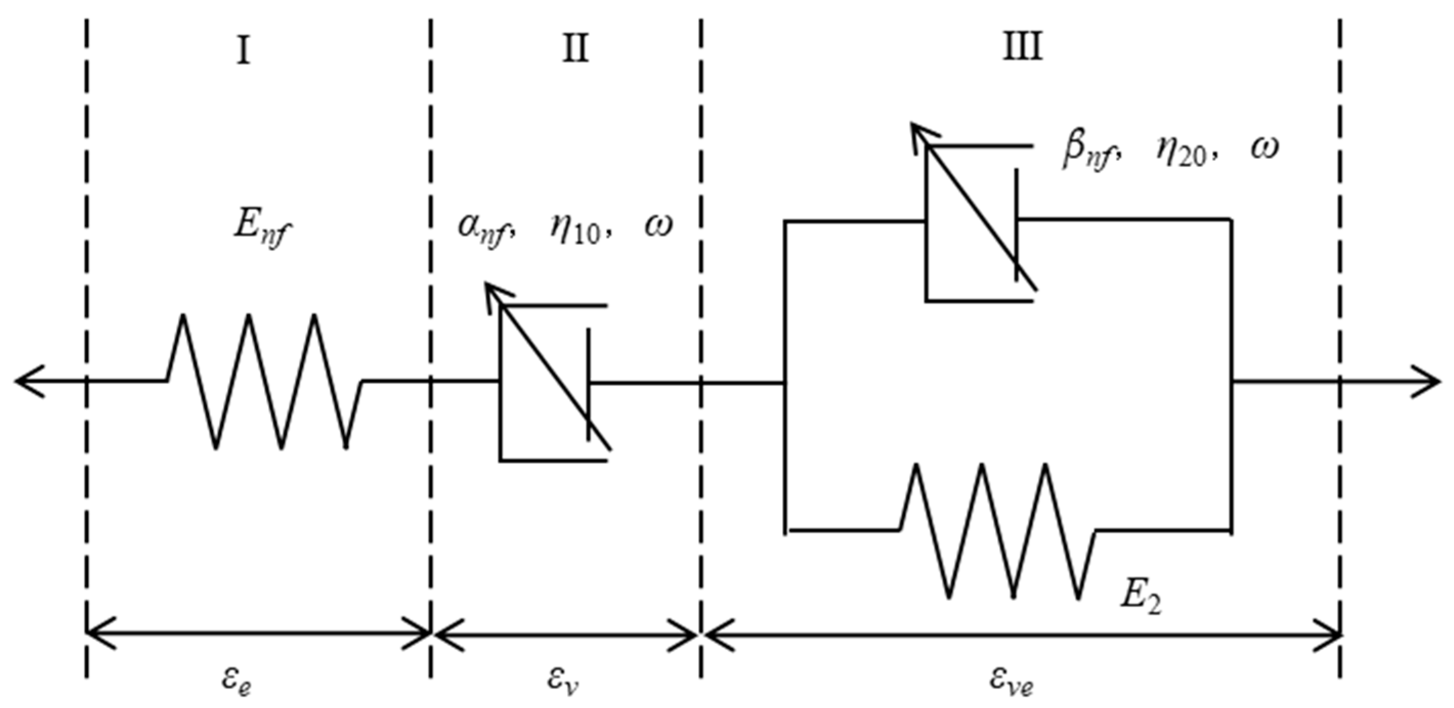
2.1.1. Modified Nonlinear Fractional-Order Shale Creep Model

As mentioned, the typical rock creep curve generally consists of transient (decelerating rate), secondary (constant rate), and tertiary (accelerating rate, leading to failure) stages. This work does not consider the third stage as it is hardly achieved during shale gas exploration [49,50,51]. Therefore, the primary motivation of this section is to seek an appropriate creep model describing the creep behaviors of the first two stages. To achieve the above goal, we propose a modified nonlinear fractional-order shale creep model, and the components and arrangement mode are shown in Figure 2.
The Hooke spring, frictional element, and modified Kelvin–Voigt element are strung together in a series to represent viscoelastic deformation. The relationship between total stress and strain can be written as follows:
ε s = ε h + ε f + ε k σ s = σ h = σ f = σ k
where the subscripts h, f, and k represent the Hooke spring, frictional element, and modified Kelvin–Voigt element, respectively. Additionally, we have the following relationship for the Hooke element:
ε h = σ h E n f = σ s E n f
where Enf denotes Young’s modulus of the Hooke element.
For the frictional element, we also have
ε f ( t ) = σ f η 10 t α n f E 1 , α + 1 ω t      ( 0 α n f 1 )
where η10 denotes the initial viscosity coefficient, α denotes frictional order, and ω denotes the viscosity coefficient attenuation factor, which is related to the loading time and stress. Eγ,β is the Mittag-Leffler special function, E γ , β x = k = 0 x k Γ γ k + β .
The stress and strain relationship of modified fractional Kelvin–Voigt element can be described as follows:
ε k = ε k H = ε k F σ k = σ k H + σ k F
where εkH and σkH represent the stress and strain, respectively, of the Hooke element in the modified fractional Kelvin-Voigt model. Similarly, εkF and σkF denote the stress and strain, respectively, of the fractional element in the modified fractional Kelvin–Voigt model. The following equation should be included as a supplement to the above equation:
σ k H = ε k H E n f
σ k F = η 20 e ω d β n f ε k F d t β n f
where Enf denotes Young’s modulus of the Hooke element in the fractional Kelvin–Voigt model. η20 denotes the initial viscosity coefficient in the fractional Kelvin–Voigt element, and β is the fractional order.
Then, we have the following equation:
σ k = E k H ε k H + η 20 e ω d β n f ε k F d t β n f
σk is kept invariable during the loading stress history. After the application of Laplace transformation in the frequency domain, Equation (7) becomes
1 s σ k = E k H ε k H ( s ) + η 20 e ω s β n f ε k F ( s )
It is also written as follows:
ε k ( s ) = σ k s 1 η 20 e ω ( s β n f + E k F η 20 e ω )
Then, a Laplace inverse transformation with the double-parameter Mittag-Leffler equation is employed, and the stress–strain relationship of the modified fractional Kelvin–Voigt element can be obtained:
ε k ( t ) = σ k η 20 t β n f E β n f , β n f + 1 E 2 η 20 e ω t β n f
With the above equations, the constitutive equation for the modified fractional creep model can be written as
ε s ( t ) = σ E n f + σ η 10 t α n f E 1 , α n f + 1 ω t + σ η 20 t β n f E β n f , β n f + 1 E 2 η 20 e ω t β n f

2.1.2. Navier-Type Governing Equation for Shale Reservoir

Combining the governing equation for linear poroelastic deformation [52] with the viscoelastic constitutive equation (Equation (11)), we obtain the deformation governing equation for the poroelastic–viscoelastic coupling mode as [5]
G u i , k k + G 1 2 v u k , k i + ε c , i ( t ) J   i ( t ) = α h p h , i + α n p n , i + α o p o , i + K ε o , i ( p o ) + f i
where J(t) represents the creep compliance defined as the ratio of viscoelastic strain to viscoelastic stress, the first two terms on the left represent the elastic deformation of the reservoir, and the third term denotes the creep deformation. The first three terms on the right denote the body stress due to the fluid pressure in hydraulic fracture, natural fracture, and organic matter, and the fourth term denotes the adsorption stress in the shale matrix, usually described by the Langmuir equation [43].

2.2. Governing Equation for Gas Flow

In this work, the traditional triple porosity approach [53], consisting of hydraulic fracture, natural fracture, and matrix methods, replicates the gas flow process for shale reservoirs [52]. Due to its high permeability, the non-Darcy flow is employed in hydraulic fracture systems [54]. The concept of apparent permeability is applied to describe the gas flow in natural fractures (nanotubes) because of the gas slip effect with the effective diffusion model specified for diffusion in the shale matrix [43].

2.2.1. Gas Flow in the Hydraulic Fracture System

The mass conservation law for gas flow in the fracture system is given as [55]
m h t + J h = Q h + Q h 2 n
in which mh represents the flow mass, Qh represents the flow source or sink, and Qh2n represents the mass transfer term between the hydraulic fracture and natural fracture. The mass flux Jh of the fluid can be calculated as [56]
J h = ρ h v h   and   v h = k h μ h δ h p h
in which kh is the intrinsic permeability, µh is the viscosity, and ph is the pore pressure. In this work, the Forchheimer equation is applied to describe the Non-Darcy effect as [54], and δh is a correction coefficient defined as follows:
δ h = 1 1 + k h μ h ρ h β h v h
The parameter βh is related to the permeability of the porous media [57,58]. Based on the work of Cooke [59], the βh factor can be expressed as a power law of permeability kh as follows:
β h = γ k h η
in which γ and η are the reservoir-specific coefficients.

2.2.2. Slip Flow in the Natural Fracture

The flow regime in a natural fracture can be described by slip flow, and the mass conservation law is [40]
m n t + J n = Q n Q h 2 n + Q n 2 o
where Qn is the mass source term, Qn2o is the mass transfer between natural fracture and organic pores, and Qh2n represents the mass transfer rate between the hydraulic and natural fracture systems.
The gas mass content mn contains free-phase gas and the gas mass source applied by the organic system [54]:
m n = ρ n ϕ n + ρ g a ρ s m o r
where φn is the porosity and ρn is the gas density in the inorganic system. Jn is the mass flux in the form of a pressure gradient according to the modified Darcy equation:
J n = k a p n μ ρ n p n
where pn is the pore pressure in natural fracture and kapn is the apparent permeability of the natural fracture system:
k a p n = ( 1 + 4 K n n 1 + K n n ) k n
where Knn represents the Knusen number of the natural fracture system, and kn denotes the intrinsic permeability of the natural system. The mass transfer rate between the hydraulic fracture and the matrix system is in the free phase and proportional to the gas pressure:
Q h 2 n = σ n k a p n μ ρ n ( p n p h )
where σn is the shape factor.

2.2.3. Gas Diffusion in Organic Matter

The mass transfer rate between the inorganic system and the organic system is determined by the diffusion time in the organic matter [43]:
Q n 2 o = ρ g a ρ s d m o r d t = ρ g a ρ s 1 τ [ m o r m e ( p w a l l ) ]
where ρga denotes the gas density at standard atmospheric pressure, ρs denotes the shale reservoir density, and mor denotes the gas content in organic matter. me(pwall) denotes the gas concentration in equilibrium with the interface pressure pwall. In this equation, the diffusion time of organics is expressed as follows:
τ = 1 λ D
where D (m2/s) is the effective diffusion coefficient in organic matter [43] and λ is a shape factor. Our work assumes a pseudo-steady state, and the pressure applied at the interface pwall is equal to the natural fracture pressure pn. The absorbed gas content in equilibrium me(pwall) is calculated by the Langmuir isotherm:
m e ( p w a l l ) = V L p i n P L + p i n
where VL and PL represent the Langmuir volume and pressure constants, respectively.

2.3. Permeability Models

To achieve the coupling of shale reservoir deformation and gas multiscale flow, it is necessary to incorporate permeability models for hydraulic and natural fracture. In this study, the concept of internal strain is employed to describe the evolution of permeability in natural fractures. The deformation and embedding of proppant and the creep deformation of hydraulic fractures is also considered in the hydraulic permeability model.

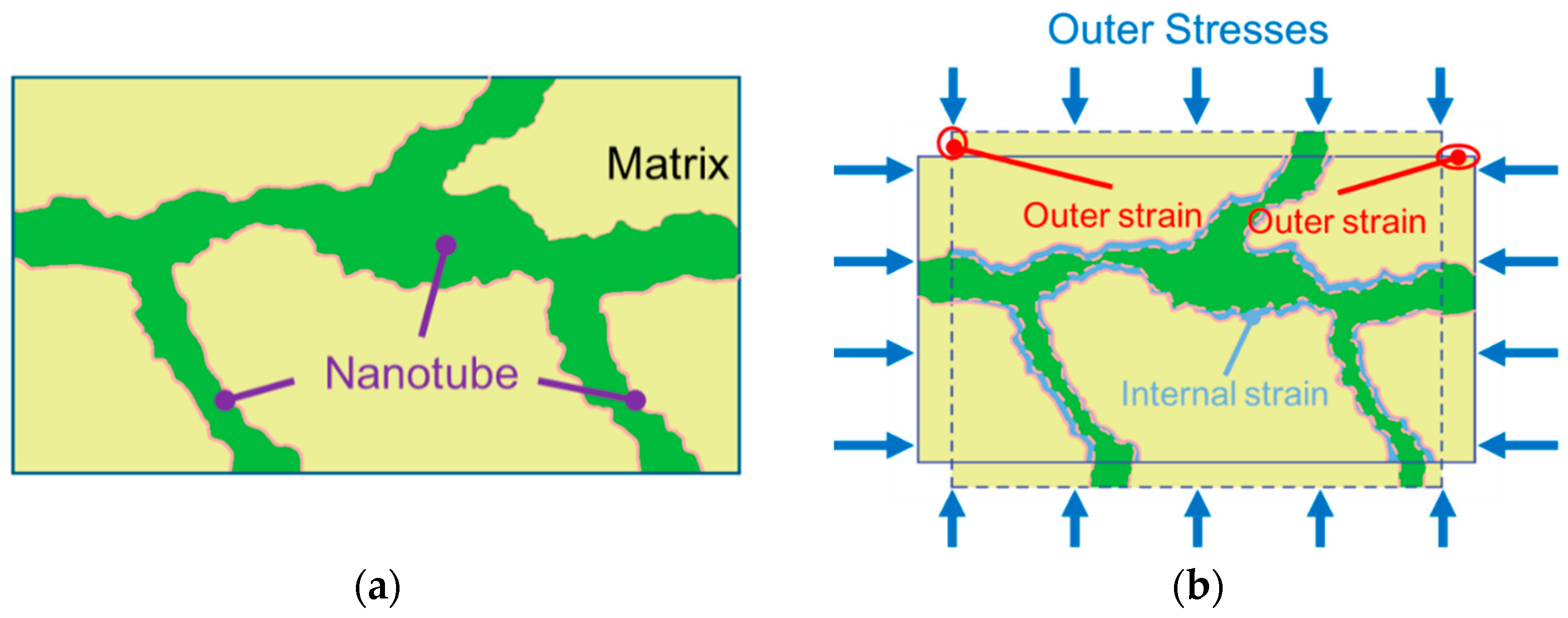
2.3.1. Definition of Internal Strain

As observed in the creep deformation and gas seepage experiment, the permeability curve experiences a significant decrease even with a minor change in volume strain. Furthermore, the loading stress remains constant throughout the loading process, rendering the traditional effective stress-based permeability models unsuitable. To address this limitation, a new permeability model based on internal strain is introduced, as depicted in Figure 3. In this study, we define internal strain as the strain directly applied to the fracture or nanotube [60,61]. In essence, internal strain results from the mechanical interaction between the fracture and matrix and is pivotal in permeability evolution.
To adequately describe the variation in the internal strain, an internal parameter is defined as [62]
α = ε i n t ε o u t
where εint represents the internal strain and εout represents the outer strain. Additionally, based on the observations between the internal strain and permeability evolution, an exponential relationship can be described to define the relationship between internal strain parameter and deformation time [63]:
α = α 0 e γ t + c
where α0 denotes the initial internal parameter value, t represents time, and γ is a fitting parameter. Then, the relationship between internal strain and outer strain can be stated as [63]
ε i n t = α 0 e γ t + c × ε o u t

2.3.2. Intrinsic Permeability of the Natural Fracture

The porosity of the fracture system is related to the effective strain according to previous studies [60]:
ϕ n ϕ n 0 = 1 + α n ϕ n 0 Δ ε n e
where φn0 is the initial inorganic matrix porosity and the subscript n represents the natural fracture. The effective strain is the sum of the global strain and local strain of the inorganic system:
Δ ε n e = Δ ε n g + Δ ε n l
The global strain of the inorganic matrix is the result of the global strain of the reservoir and the compressing strain applied by the organic system induced by gas pressure and adsorption strain:
Δ ε n g = Δ ε v ( p h p n ) K n m ( p o p n ) K n m γ ε L p o P L + p o ε i n t
where Knm is the bulk modulus of the inorganic system, εL is the Langmuir strain constant, and γo is a parameter measuring the impact of adoption strain of organic matter on natural fracture. The local strain of inorganic matter is applied by the compressing strain of gas pressure:
Δ ε n l = Δ p n K n s
where Kns is the bulk modulus of the natural fracture skeleton. The typical relationship between porosity and permeability is the cubic law:
k n k n 0 = ( ϕ n ϕ n 0 ) 3 = ( 1 + α n ϕ n 0 Δ ε n e ) 3

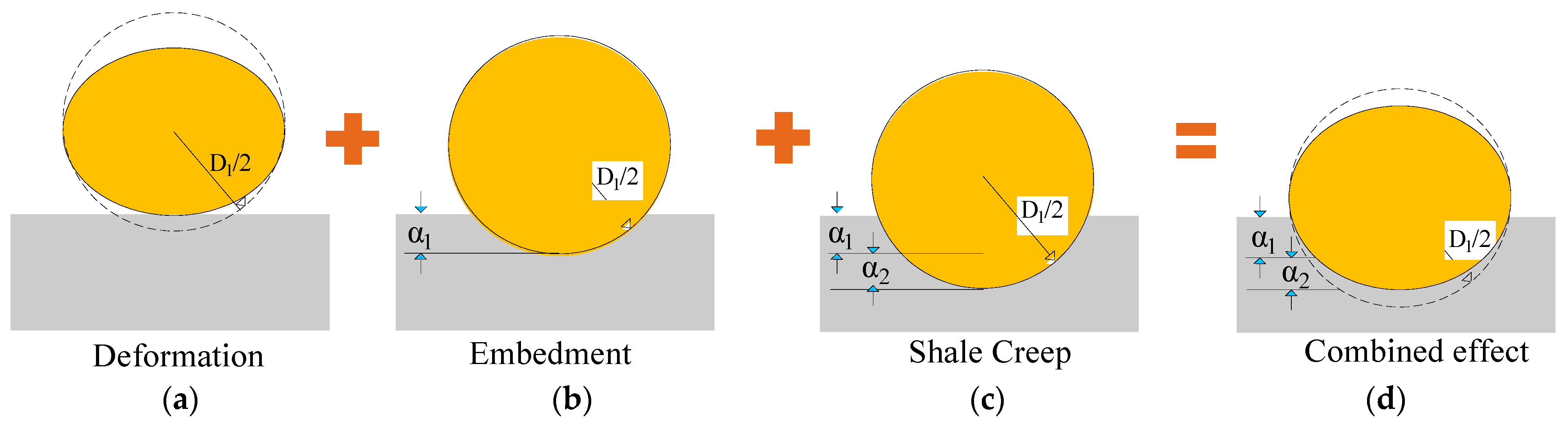
2.3.3. The Permeability Model of Hydraulic Fractures

Proppants are injected into reservoirs with hydraulic fracturing to support hydraulic fractures and maintain high conductivity. The properties of both hydraulic fractures and proppants should be considered in the hydraulic fracture permeability model. To simplify the calculation process, the following assumptions are made [48]: (i) Proppants are assumed to be spherical with a uniform diameter, and crushing is not considered. (ii) The roughness of the hydraulic fracture surface is disregarded. During the gas depletion process, the proppant deformation and embedment should be considered in the permeability model of hydraulic fractures. In addition, the creep behavior of hydraulic fractures should be included because of their high clay content. The deformation process of the proppant is illustrated in Figure 4 [64].
The model of fracture aperture considering proppant deformation and embedment could be expressed as [65].
Δ b t = 1.04 D ( K 2 p c ) 2 / 3 { ( 1 v 1 2 E p ) 2 / 3 + D 1 D [ ( 1 v 1 2 E p + 1 v 2 2 E h ) 2 / 3 ( 1 v 1 2 E p ) 2 / 3 ] }
Δ b d = 1.04 D ( K 2 p c 1 v 1 2 E p ) 2 / 3
Δ b e = 1.04 D 1 ( K 2 p c ) 2 / 3 [ ( 1 v 1 2 E p + 1 v 2 2 E h ) 2 / 3 ( 1 v 1 2 E p ) 2 / 3 ]
where bt represents the total variation of the hydraulic fracture aperture. bd represents the value of proppant deformation. be represents the value of proppant deformation. D1 is the diameter of proppant grains. Eh is the elastic modulus of the formation. v2 is the Poisson ratio of the formation. E1 is the elastic modulus of the proppant. v1 is the Poisson ratio of the proppant. pc denotes the closure pressure, where pc = σhpi. σh represents the minimum horizontal principal stress. pi is the fluid pressure within the hydraulic fracture. K denotes the distance coefficient, with K = 1, because proppant grains are tightly connected. D is the initial fracture aperture. In this study, we propose a modified nonlinear fractional-order shale creep model to characterize the viscoelastic behavior of the hydraulic fracture. The model consists of three components—Hooke spring, frictional element, and fractional modified Kelvin–Voigt element—connected in series, as illustrated in Figure 2. Within this model, the Young’s modulus in Equation (34) should be replaced by
1 E h = 1 E h e + 1 η h f t α h f Γ ( 1 + α h f ) + 1 E h k ( 1 E α h k , 1 ( t α h k τ h k ) )
in which the second subscripts h, f, and k represent the Hooke spring, frictional element, and modified Kelvin–Voigt element, respectively. Additionally, the following equation is essential for linking permeability evolution and fracture aperture [66]:
k h k h 0 = 1 + Δ b b 0 3

2.4. Coupling Process

In this work, we propose a modified nonlinear fractional-order creep model to describe the viscoelastic behavior of shale reservoirs and hydraulic fracture systems via the triple porosity approach to describe the multiscale gas flow in shale reservoirs. The coupling process can be summarized in Figure 5 and described as follows:
(i)
The gas flow in the hydraulic fracture system impacts the creep deformation of the shale reservoir (Equation (12)) and enlarges the closure pressure—pc. As a result, the aperture and permeability of hydraulic fractures decrease following Equations (34) and (37). As a return, the variation in permeability impacts the gas flow characteristics in hydraulic fractures as defined in Equation (13).
(ii)
The gas depletion in natural fractures lowers the gas pressure in shale reservoirs and impacts the stress–strain state of shale reservoirs, as determined by Equation (12). On the other hand, the strain in shale reservoirs impacts the permeability of natural fractures (Equation (32)), and the creep strain is considered. As a result, the redefined permeability determines the gas pressure distribution following Equation (17);
(iii)
The gas flow in hydraulic fractures, natural fractures, and shale matrices all impact the stress state of shale reservoirs and, thus, creep deformation. In addition, mass transfer occurs between different systems. The mass transfer term between hydraulic fractures and natural fractures is co-dominated by the pore pressure difference between them and the permeability in natural fracture systems (Equation (21)). The mass transfer between natural fractures and matrix systems is determined by the effective diffusion coefficient (Equation (22)) in the matrix system.

3. Model Verification

This work uses the commercial software COMSOL Multiphysics (version 5.4(a)) to replicate gas depletion characteristics in the field. Meanwhile, the impacts of creep deformation from hydraulic fractures and natural fractures on gas production are investigated.

3.1. Field Data Selection and Geometric Model

The Barnett shale is the main source rock for the Paleozoic petroleum system in the Fort Worth Basin and is currently one of the most prolific gas reservoirs in the U.S. The reservoir is buried at about 2200–2600 m depth with the in situ stress of Shmin = 44~47 MPa, Shmax = 64~85.5 MPa, and Sv = 65 MPa [67]. A significant creep deformation can be observed under the in situ stress state. Well 314 is a horizontal well with multistage hydraulic fracturing treatment. A total of 28 hydraulic fractures are observed with a fracture spacing of 30.5 m. Production data for over 1600 days are employed for model validation as the impact of creep deformation becomes significant with depletion time. As field microseismic observations suggest [5,68], an ellipsoidal shape can be assigned to describe the simulated reservoir volume (SRV). In the case of well 314, the smaller fracture spacing links the SRV of each hydraulic fracture together, forming a cuboid with eight fillet angles.
In the simulation model, the reservoir is set as a cuboid with a volume of 1000 m × 500 m × 100 m and a linked SRV of approximately 860 m × 100 m × 90 m. Figure 6 illustrates the geometry and meshing elements for the simulation model and SRV. For the meshing, the SRV region is extensively meshed with a maximum element size of 10 m and a minimum element size of 4 m. In contrast, in the USRV region, the remaining part of the simulation model is roughly meshed, and the finer feature in COMSOL Multiphysics is applied. After meshing, a total of 201,879 elements are generated, with an average quality rating above 0.8. The simulation is conducted using a self-assembled high-performance workstation (located in our lab Shenyang, China) equipped with a double Intel (R) Xeon (R) Platinum 8370 CPU and 256 GB of RAM. Each run of the simulation requires 90 min of computing time.

3.2. Module Selection and Parameter Determination

To implement the above fully coupled model, COMSOL Multiphysics (version 5.4) was used as follows: (i) The solid mechanics module replicates the elastic deformation of shale, and the deformation of the frictional viscoelastic element is calculated in MATLAB (2019b) for each iteration step. COMSOL with MATLAB is utilized to transfer the strain values. (ii) Gas flow within a triple porosity medium is achieved using the Darcy law module to simulate gas flow in the natural fracture system, and the Forchheimer equation is applied to describe non-Darcy flow in the hydraulic fracture. A general partial differential equation is employed to characterize gas diffusion in the matrix. (iii) The coupling process between creep deformation and gas flow capability is accomplished through permeability models defined in the variable definitions.
In the mechanical model, a uniaxial strain condition is assumed. A constant pressure with the value of 65 MPa is applied to the top side, while roller boundary conditions are applied to the other sides. In the gas flow model within the fracture system, a constant bottom-hole pressure of 3.45 MPa [69] is used at the well to simulate the extraction pressure of the hydraulic fracture. No-flow boundary conditions are applied to the other boundaries. No flow boundary conditions are applied for the gas flow model in a natural fracture and organic matrix because hydraulic fractures are not directly connected. The reservoir information of Barnett shale was collected from the literature [6,67,68,69] and is listed in Table 1. In particular, the dependence of characteristic parameters (η, α β, and so on) on effective stress is considered.

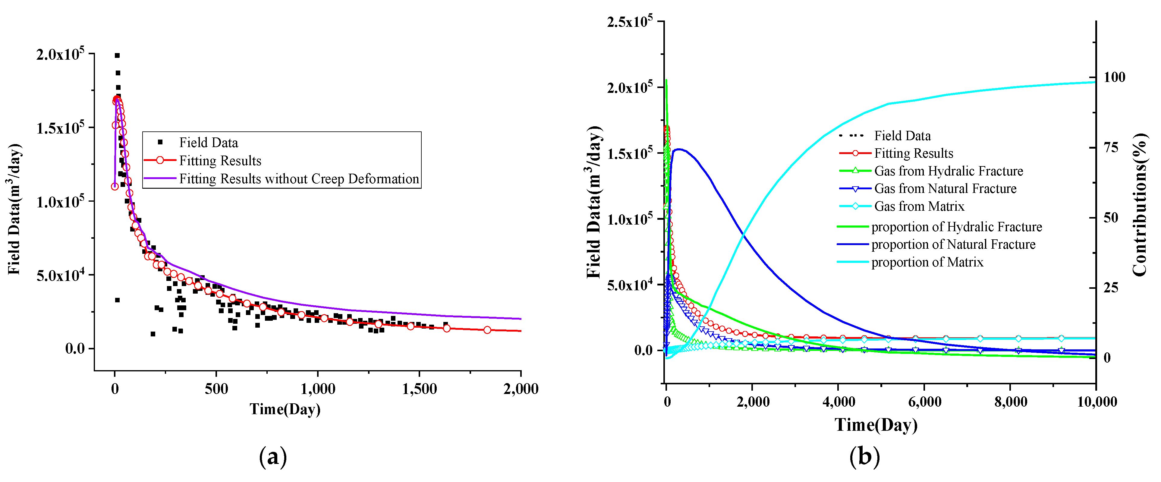
3.3. Verification Results

The results of matched gas production rates and amounts are shown in Figure 7a,b. As demonstrated, our model can accurately replicate the gas depletion characteristic with goodness-of-fit values above 0.85. However, the model cannot fit the early data well because of the significant fluctuations in the field data and the disregard for water flow in the proposed model. The gas depletion characteristic in the late stage is accurately replicated because the impact of water flow can be ignored, and most of the gas is depleted from the shale matrix. The prediction also indicates that low gas flow rates will continue for an extended period. Also in our current model, the relationship between the characteristic parameter and declined gas pressure is considered. The impact of this relationship on gas depletion is investigated in Figure 7a. The ignorance of this relationship would enlarge the gas flow rate, especially for the long-term gas production profile, as more creep deformation can be determined with larger effective stress. Furthermore, we illustrate the gas resources and contributions from different sub-components based on the triple-porosity system. The gases in hydraulic fractures play a significant role at early stages but account for a small proportion of the gas in the long term, as only a tiny part of the gases are stored in hydraulic systems during the stimulation process. The gas flow rate in the middle stage is mainly due to the gas flow in the nanotube and can be maintained at a relatively high level. In the last stage, the gas in the matrix systems is fully considered. These characteristics are similar to our previous work [40].

3.4. Permeability Evolutions

In the proposed model, the permeabilities of both hydraulic fractures and natural fractures vary during gas depletion: (i) the first term is related to the proppant deformation and proppant embedment; (ii) the second term is dependent on gas desorption, effective stress, and creep deformation of the reservoir. In this section, the permeability evolution and its dominant agents are investigated.
The permeability evolution of the hydraulic system is first investigated, with the results displayed in Figure 8a. The permeability sharply decreases during the early stage because of proppant embedment, firstly controlled by the elastic behavior, and continues to decline due to creep deformation, with its dominant role increasing with time. The contributions of proppant embedment and creep deformation are also illustrated, as shown in the dashed line. In this case, the embedment deformation accounts for 80%, and the creep deformation accounts for 18% of the initial deformation but also increases with time and accounts for approximately 22% of the total deformation at the end of 10,000 days.
The permeability evolution of natural fracture systems is also addressed in Figure 8b. During gas depletion, the global strain lowers the permeability, while in contrast, the decreased adsorption strain increases, with the interaction strain first increasing and then decreasing. In addition to the well-studied strains, creep strain also contributes to the decrease in permeability values. The contributions of different mechanisms are also represented by the dashed line in Figure 8b. As shown, the interaction strain and adsorption strain have a relatively small impact. The proportion of global strain decreases with time, while conversely, the proportion of global strain increases with time.

4. Results and Discussion

In the preceding section, the proposed model governing the coupled process of creep deformation and multi-gas flow was validated in a shale reservoir using field data collected from Barnett shale. In this section, we examine the effects of the newly introduced parameters, which govern the creep behavior of natural fracture and hydraulic fracture systems, on permeability evolution and the associated gas depletion characteristics.

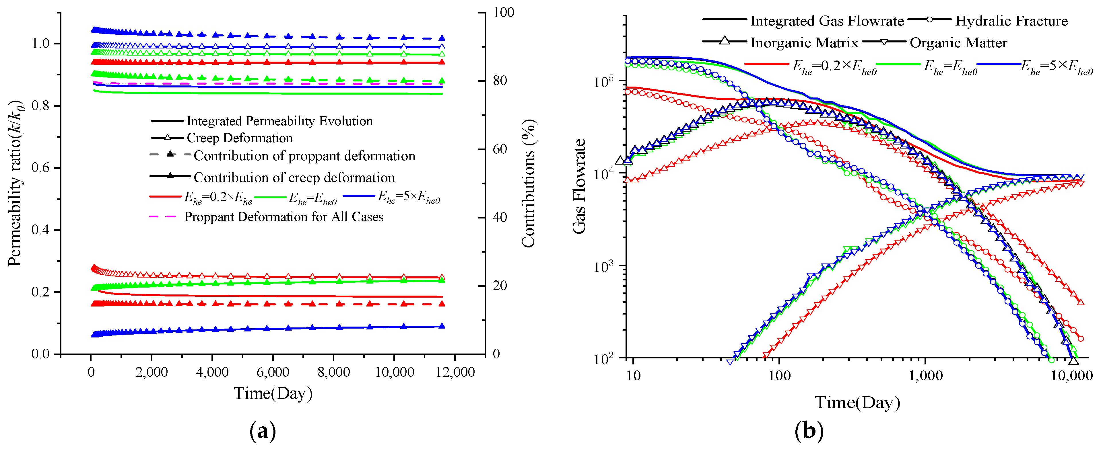
4.1. Impacts of the Creep Behavior of the Hydraulic Fracture System

The hydraulic fracture serves as the main flow channel linking the shale reservoir and production well, and its creep behavior is significantly greater than that of the matrix because of its easy deformation and the presence of hydraulic fluid [70]. In this section, we address the impacts of parameters that control the creep behavior of the hydraulic fracture system on permeability evolution and gas depletion characteristics. As shown in Equations (33)–(37), the properties of the hydraulic system and proppants influence permeability evolution, which are discussed in this section.

4.1.1. The Impact of Ehe

As indicated in Equation (36), the creep behavior of hydraulic fractures is controlled by the values of the parameters Ehe, ηhf, and αhk. The parameter Ehe controls the instantaneous response of hydraulic fractures to loading stress through its impacts on permeability evolution and gas depletion characteristics, as addressed in Figure 9. In panel Figure 9a, the solid line represents the integrated permeability value, and the dashed line represents the permeability evolution due to proppant deformation, with solid lines marked with upper triangles representing permeability evolution due to creep deformation. The dashed line with a solid upper triangle denotes the contribution of proppant deformation to the permeability variation, while the hollow lines denote the contribution of creep deformation; in panel Figure 9b, the solid lines represent the integrated gas flow rate, with the lines marked with circles and upper and lower triangles denoting gas resources from hydraulic fractures, the inorganic matrix, and organic matter, respectively. In both panels, red represents the value of 0.2× Ehe, green represents Ehe, and blue denotes 5× Ehe. As can be observed (Figure 9a), a smaller value of Ehe results in a more significant reduction in permeability at the initial time as the permeability decreases to 0.2× khf0 when the smallest Ehe is specified. Additionally, a smaller Ehe results in a greater contribution of creep deformation to the permeability evolution. However, this value has little impact on the permeability evolution over a long period, as it is mainly determined by the parameters αhk and ηhf. The flow rate is also illustrated in Figure 9b, where a larger Young’s modulus results in a greater gas flow rate. There are significant differences with varied Ehe values at the beginning, and the discrepancy vanishes with time. Moreover, the value of Ehe also impacts the gas flow rate in the inorganic matrix and organic matter, as the hydraulic fracture system bridges the production well and shale reservoir. Similarly, a lower gas flow rate can be observed for a lower Young’s modulus.

4.1.2. The Impact of ηhf

Later, the impacts of ηhf, which represents the initial viscosity coefficient, on the permeability evolution and gas flow rate are investigated with the results displayed in Figure 10a,b, respectively. The meanings of the variation lines in Figure 10 are the same as those in Figure 9. Red represents the value of 0.2× ηhf, green represents ηhf, and blue denotes 5× ηhf. It is clearly shown that the three computing scenarios have the same initial permeability, indicating that the value of ηhf has no influence on the initial value of kh. A smaller value of ηhf leads to a greater reduction in the permeability. As demonstrated in the figure, the permeability decreases to 0.1× kh0 on day 800, at a value of 0.2× ηhf. Additionally, the contributions of creep deformation to permeability variations decrease with increasing ηhf. Correspondingly, a lower ηhf leads to a lower gas flow rate because of the lower permeability, while its impact on the gas flow rate increases with increasing gas depletion time. Compared with the flow rate with varying Ehe, the impact of the flow rate with varying Ehe is smaller because of the same initial value.

4.1.3. The Impact of ahf

In this study, we introduced a fractional-order-based permeability model to characterize the creep behavior of the hydraulic fracture system. We investigate the permeability evolution and gas flow rate characteristics with varying fractional orders, represented by ahf, and present the results in Figure 11. The meanings of the variation lines in Figure 11 are the same as those in Figure 9. Red represents the value of 0.5× ahf, green represents ahf,, and blue denotes 1.5× ahf. Like in the case of ηhf, the ahf has little impact on the initial permeability. Additionally, a larger ahf results in greater creep deformation of hydraulic fractures, together with a greater contribution to the permeability variation, and therefore leads to a significant reduction in the permeability during long-term evolution. Additionally, a larger ahf leads to a lower gas flow rate because of the lower permeability, while no significant difference is observed for ahf and 0.5× ahf.
In this section, the impacts of parameters Ehe, ηhf, and αhf, which control the creep characteristics of the hydraulic fracture system, on the permeability evolution and gas depletion profile are investigated. Comparing Figure 9, Figure 10 and Figure 11, the following is evident: (i) The value of Ehe significantly affects the initial permeability value, but it has minimal influence on the long-term permeability evolution. In contrast, no apparent discrepancy is observed in the initial permeability with varied value of ηhf and αhf and a significant difference is determined for long-term evolution. (ii) All the parameters affect the gas depletion profile, while their impacts are considered in the initial stage, as the gas transport ability in the natural and matrix systems mainly determines the gas depletion characteristic in the later stage. Compared with the impacts of these three parameters, the parameter Ehe has a more significant impact than the other two parameters because it has a much lower initial permeability. However, the dominant roles of ηh and αh increase with depletion time.

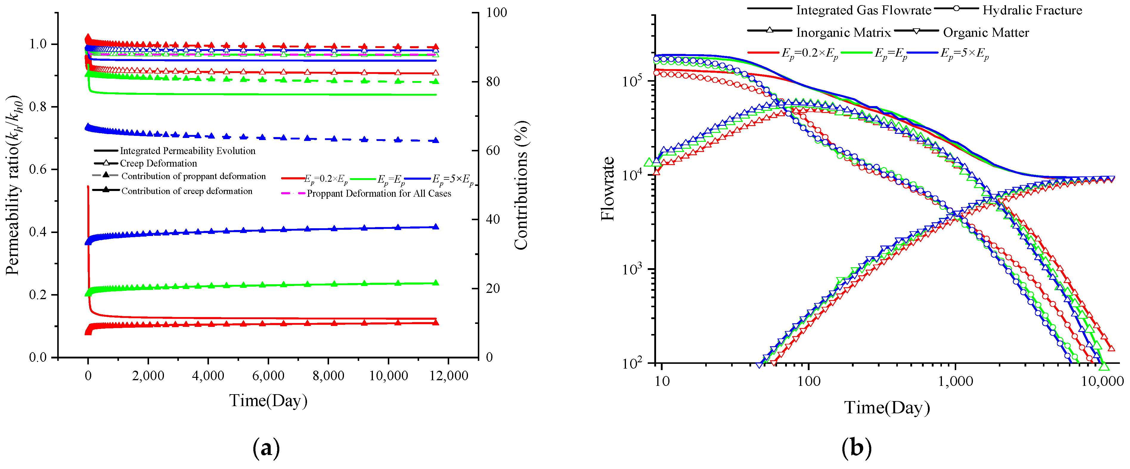
4.2. Impacts of the Proppant Type

During hydraulic fracturing, proppant particles are combined with fracturing fluids and subsequently injected into the fracture system. This process prevents fracture closure, maintains fracture openings, and achieves high fracture conductivity [70]. Glass beads, ceramic beads, and sands are most commonly employed with Young’s moduli ranging from 0.15 GPa to 100 GPa [65]. In this section, the impact of Young’s modulus of the proppant is investigated with the results displayed in Figure 12a,b. The meanings of the variation lines in Figure 12 are the same as those in Figure 9. Red represents the value of 0.5× Ep, green represents Ep, and blue denotes 1.5× Ep. As indicated in Equation (36), Young’s modulus of the proppant affects both the permeability components dominated by the proppant deformation and creep deformation; therefore, in Figure 12a, both effects are drawn. Obviously, a smaller Young’s modulus results in a greater reduction in permeability both in the proppant deformation term and in the creep deformation term. Young’s modulus of the proppant significantly impacts the proppant deformation, with a slight divergence observed for creep deformation. Additionally, a smaller Young’s modulus results in a greater contribution of proppant deformation to permeability evolution, while the contribution slightly decreases with depletion time. Its impact on the gas flow rate is also addressed. Correspondingly, a lower Young’s modulus results in a lower gas flow rate because of its much smaller Young’s modulus. Additionally, its impact on the gas flow rate decreases with depletion time.

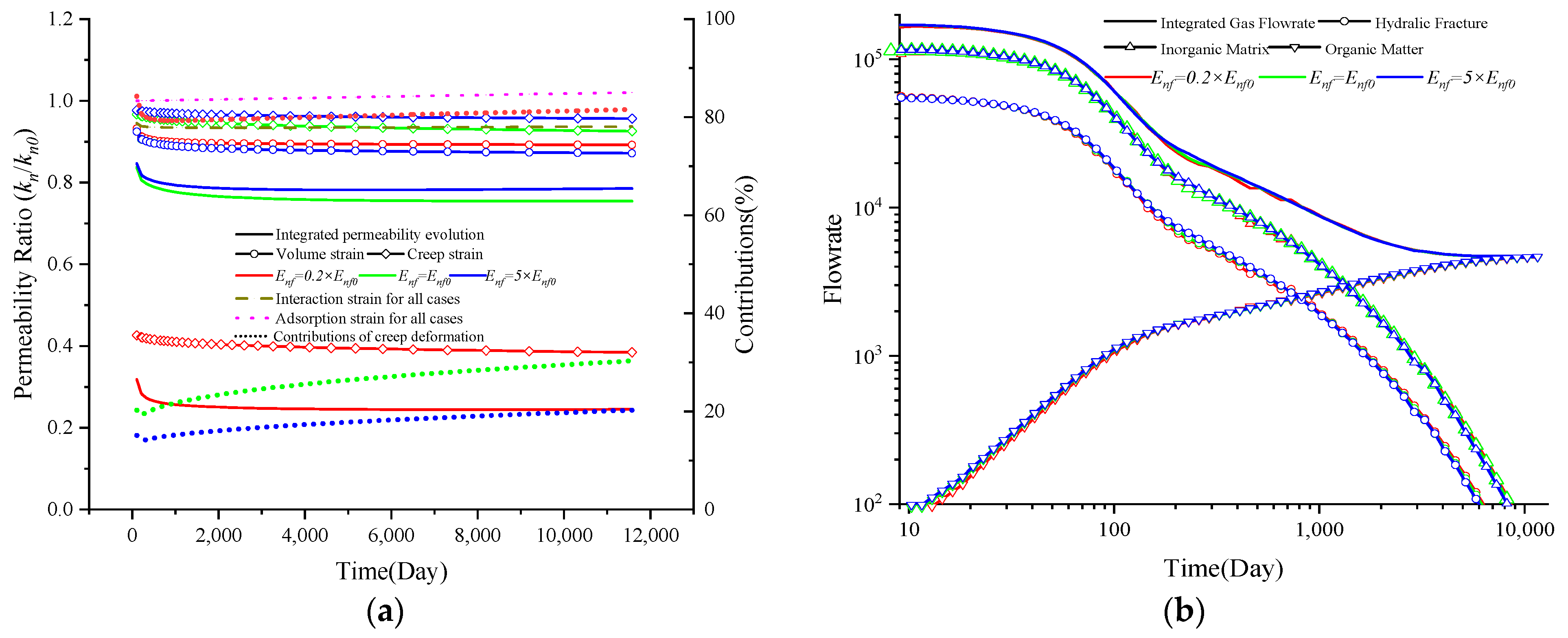
4.3. Impacts of the Creep Behavior of the Natural Fracture System

The above section conducts a sensitivity analysis of the parameters controlling the creep behavior of hydraulic systems. In this section, the impacts of the parameters dominating the creep behavior of the natural system are examined.

4.3.1. The Impact of anf

In this work, we propose a fractional order-based creep model to describe the viscoelastic behavior of natural fractures, as shown in Equation (11). The dependence of permeability evolution and gas flow rates on fraction order (anf) are checked with results displayed in Figure 13a,b. In Figure 13a, the solid line represents the integrated permeability value, the solid line with a circle denotes the volumetric strain, and the solid line with a rhombus denotes the creep strain. The dotted line represents the adoption strain, and the dashed line denotes the interaction strain. The short, dotted lines specify the contribution of creep deformation with various values of anf. In both figures, red represents the value of 0.5× anf, green represents anf, and blue denotes 1.5× anf. The value of anf has a particular impact on the permeability evolution and gas depletion characteristic: (i) the larger value of anf results in significant creep deformation of the natural fracture system and, therefore, a greater reduction in the permeability; (ii) a larger value also results in a greater contribution of creep deformation to the permeability variation as the contribution increases with depletion time; and (iii) a larger value of anf results in a smaller gas flow rate, while it has little impact on the initial gas flow rate, with a larger discrepancy observed after 100 days. This is mainly because the gas resources collected in the early time mainly originated from the hydraulic system.

4.3.2. The Impact of βnf

In contrast to the creep model for hydraulic fractures, a fractional-order-based Kelvin–Voigt element has been incorporated with the friction order denoted by βnf. In this section, the dominant roles of βnf in determining the permeability evolution and gas flow rate are characterized, and the results are displayed in Figure 14a,b. The meanings of the variation lines in Figure 14 are the same as those in Figure 13. Red represents the value of 0.5× βnf, green represents the value of βnf, and blue denotes the value of 1.5× βnf. Similar to the impact of anf, it almost has no impact on the initial gas flow rate, and its impact is concentrated in the middle term. In addition, other characteristics are determined: (i) a larger value of βnf leads to a greater reduction in permeability and a lower gas flow rate, together with a greater contribution of creep deformation to permeability variation; (ii) additionally, the impacts are concentrated on the latter term after 100 days.

4.3.3. The Impact of Enf

In the proposed creep model based on the order of friction, the parameter Enf controls the immediate response to the applied stress, as shown in Figure 15a,b. The meanings of the variation lines in Figure 15 are the same as those in Figure 13. Red represents the value of 0.5× Enf, green represents Enf, and blue denotes 1.5× Enf. The following characteristics are determined: (i) different values of Enf result in varying initial permeability values, with lower values of Enf leading to smaller permeability values; (ii) lower values of Enf also lead to a greater contribution of creep deformation to permeability evolution, with this contribution increasing over time; (iii) long-term permeability has little dependence on the value of Enf; (iv) similarly, lower values of Enf result in lower flow rates, with little influence on the early term, but a significant impact on the long-term gas flow rate.

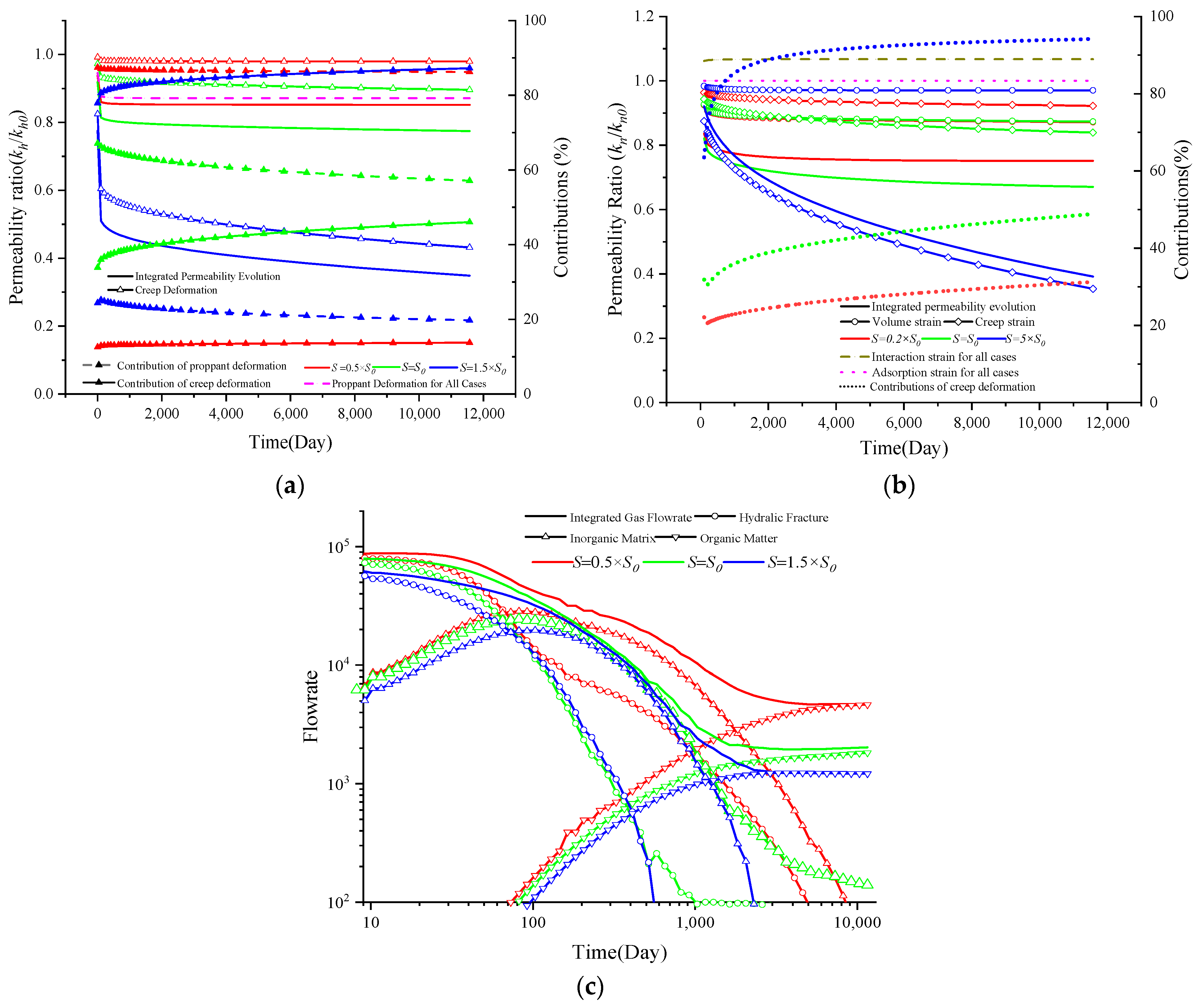
4.4. The Impacts of Formation Stress

Shale gas reservoirs are widely distributed in the USA, Canada, and China, where the depth ranges from 1 km to 3 km. Moreover, the formation stress also varies, leading to different viscoelastic behavior. A previous experiment indicated that high stress results in more significant creep deformation than low stress [71]. In this section, all parameters that control the viscoelastic behavior of natural and hydraulic fracture systems are systematically varied to examine the influence of in situ stress on permeability evolution and gas depletion characteristics. The permeability evolutions of both hydraulic and natural fracture systems are presented in Figure 16a,b, respectively, while the results of gas depletion characteristics are depicted in Figure 16c. The meanings of the variation lines in Figure 16a are the same as those in Figure 9 with meanings in Figure 16b the same as those in Figure 13. Red represents the value of 0.5× S0, green represents S0, and blue denotes 1.5× S0. Formation stress has little impact on the propagation deformation-dominated hydraulic permeability evolution, as the mechanical properties of the proppant control it. However, creep deformation is significantly impacted by in situ stress, as a more considerable creep deformation leads to a greater creep deformation and, therefore, a smaller permeability. A similar observation is made for the permeability evolution of a natural fracture system: a lower permeability is associated with greater in situ stress and, therefore, greater burial depth. Additionally, a greater in situ stress also results in a greater contribution of creep deformation to the permeability variation. A larger in situ stress leads to a lower gas flow rate because of its lower permeability. Compared with other dominant factors, the role of in situ stress is more significant.

4.5. Discussion

4.5.1. Comparisons with Previous Work

The impacts of the viscoelastic behavior of shale rock on gas flow characteristics have been widely reported. Within previous works, the permeability was found to continuously decrease during a constant stress-loading environment [72,73], and some creep constitutive and permeability models were proposed to govern the coupling process of time-dependent deformation and gas flow [41,63]. Furthermore, the dominant role of the long-term conductivity of hydraulic fractures, determined by their creation behavior, was addressed [42]. Additionally, the triple porosity approach involving hydraulic fractures, natural fractures, and matrices was extensively applied to replicate the characteristics of shale gas depletion at the field scale [44,45]. However, only one constitutive model was employed to describe the viscoelasticity characteristics of shale reservoirs. This approach, involving three porous media but one deformation equation, is inappropriate because the creep behaviors of hydraulic fractures and natural fractures (nanotubes) in the shale matrix are entirely different.
In this study, we introduce a multiscaled creep deformation constitutive model to enhance the understanding of the coupling process. Specifically, we present a modified nonlinear fractional-order shale creep model with two sets of varying parameters to describe the viscoelastic behavior of hydraulic and natural fracture systems. This approach investigates the impacts of time-dependent deformation on each porous medium, and the relationships between gas depletion characteristics and creep deformation of hydraulic fractures and natural fractures are addressed. Also in the previous work, the characteristic parameters governing the creep behavior of shale reservoir are considered invariable. As a modification and correction, the dependence of characteristic parameters on the declined gas pressure is considered to accurately predict the gas depletion behavior, especially for the long term.

4.5.2. Limitations and Future Work

This current study introduces a multiscaled creep deformation–gas flow coupled model to analyze gas depletion characteristics. In this new approach, the influence of viscoelastic behavior can be assessed through the newly introduced parameters—E and η— in the friction-based creep constitutive model. These parameters are also influenced by temperature, but we have not considered variations in temperature, thermal stresses, or their combined effects on the creep behavior in this investigation [19]. Furthermore, shale reservoirs contain a certain amount of formation water, and some hydraulic fluid, which is retained in reservoirs, cannot flow back. The presence of formation water and hydraulic fluid essentially enhances the creep deformation of shale reservoirs, but this impact is not considered in this work.
In future work, a gas–water two-phase flow experiment involving in situ temperature data should be conducted to investigate the relationships among water saturation, temperature, loading stress magnitude and period, and permeability evolution. To attain the objective above, an autonomous flow and pressure control system can be employed to regulate water saturation in the core sample. Additionally, temperature control can be implemented to replicate the thermal conditions of the reservoir. Upscaling methods similar to those employed in this study can be developed to establish a connection between permeability at laboratory and field scales.

4.5.3. Guidance to the Field Application

A series of parameter-sensitivity analyses are conducted to investigate the impact of creep deformation on shale exploration. There are several ways to link the numerical model to the field scale:
(a)
History matching and extension to future analyses. In this work, a fully coupled model, including a multiscaled viscoelasticity constitutive model and a classical triple-porosity model, is proposed to investigate the impact of creep deformation on shale gas depletion characteristics. The real parameter should be determined to characterize the time-dependent deformation of the hydraulic fracture system and natural fracture system. In this work, some empirical value has been employed, which may not always be true. A creep deformation–gas seepage experiment should be conducted to measure the real value. Then the fully coupled model may be applied to history match existing gas production data and then predict subsequent production.
(b)
Implications for in situ shale gas exploitation. (i) The viscoelasticity properties of shale reservoir have a significant impact on shale gas depletion; therefore, it is essential to conduct creep deformation-gas seepage analysis of shale; (ii) the first stage of creep deformation significantly affects the initial permeability, while the second stage dominates the long-term permeability evolution. The impact of gas depletion is concentrated in the long term. (iii) Also, the properties of proppant directly affect the flow properties of the hydraulic fracture, and rates of shale gas depletion.

5. Conclusions

In this study, a creep deformation–gas flow coupled model was introduced to explore the creep behavior of shale reservoirs and its impact on gas depletion at the field scale. Initially, the new model was validated using gas production data and subsequently, a numerical experiment was conducted. Based on these investigations, the following conclusions can be made:
(a)
A multiscaled creep constitutive model is established to govern the viscoelastic behavior of hydraulic and natural fractures of shale reservoirs. Specially, the impact of effective stress on the characteristic parameter is considered. Correspondingly, a triple porosity model replicates the multi-gas flow in shale reservoirs. The permeabilities of hydraulic and natural fractures serve as the coupling parameters between them. In this approach, the creep deformation and corresponding gas flow in each subsystem are linked.
(b)
Both the properties of the proppant and shale reservoir impact the conductivity of the hydraulic fracture. A smaller Young’s modulus of the proppant leads to a greater reduction in conductivity at the initial time. The significant transient creep stage exhibits a much lower initial permeability. However, the dominant role of the second creep stage increases with depletion time. The impacts are concentrated at early times for the gas flow rate, and a smaller difference in the long-term stage can be observed for different values.
(c)
The permeability evolution of natural fractures (nanotubes) is mainly dominated by the creep characteristics and effective stress of shale reservoirs and is less controlled by the adsorption strain. Similarly, the first stage of creep deformation significantly affects the initial permeability, while the second stage dominates the long-term permeability evolution.
(d)
The in situ stress significantly impacts creep deformation, contributing to permeability evolution and further gas depletion characteristics. Obviously, greater stress results in a greater reduction in permeability for both NFs and HFs. Moreover, the deep buried formation has a lower gas flow rate.

Author Contributions

Conceptualization, Y.L.; Methodology, D.Y., Y.T., A.Z. and C.L.; Software, Y.L.; Validation, Y.T.; Formal analysis, D.Y. and Y.L.; Investigation, D.Y.; Resources, D.Y., A.Z. and C.L.; Data curation, Y.T.; Writing—original draft, D.Y., G.C. and Y.T.; Writing—review & editing, A.Z.; Visualization, C.L.; Project administration, G.C.; Funding acquisition, G.C. and C.L. All authors have read and agreed to the published version of the manuscript.

Funding

This work is partially funded by the National Key Research and Development Program of China (No. 2020YFA0711802), the National Natural Science Foundation of China (Grant No. 12002081), and the Key Project of the Natural Science Foundation of Hebei Province (Basic Discipline Research) (No. A2023210064).

Data Availability Statement

The original contributions presented in the study are included in the article, further inquiries can be directed to the corresponding author.

Conflicts of Interest

The authors declare no conflict of interest.

References

  1. Li, C.; Bažant, Z.P.; Xie, H.; Rahimi-Aghdam, S. Anisotropic microplane constitutive model for coupling creep and damage in layered geomaterials such as gas or oil shale. Int. J. Rock Mech. Min. Sci. 2019, 124, 104074. [Google Scholar] [CrossRef]
  2. Hughes, J.D. Energy: A reality check on the shale revolution. Nature 2013, 494, 307–308. [Google Scholar] [CrossRef] [PubMed]
  3. Wasaki, A.; Akkutlu, I.Y. Permeability of Organic-rich Shale. In Proceedings of the SPE Annual Technical Conference and Exhibition, Amsterdam, The Netherlands, 29 October 2014; Society of Petroleum Engineers: Amsterdam, The Netherlands, 2014. [Google Scholar]
  4. Cheng, W.; Cui, G.; Tan, Y.; Elsworth, D.; Wang, C.; Yang, C.; Chen, T.; Jiang, C. A multi-layer nanocased model to explain the U-shaped evolution of shale gas permeability at constant confining pressure. Fuel 2024, 359, 130478. [Google Scholar] [CrossRef]
  5. Cui, G.; Tan, Y.; Chen, T.; Feng, X.-T.; Elsworth, D.; Pan, Z.; Wang, C. Multidomain Two-Phase Flow Model to Study the Impacts of Hydraulic Fracturing on Shale Gas Production. Energy Fuels 2020, 34, 4273–4288. [Google Scholar] [CrossRef]
  6. Tan, Y.; Zhang, S.; Tang, S.; Cui, G.; Ma, Y.; Sun, M.; Pan, Z. Impact of water saturation on gas permeability in shale: Experimental and modelling. J. Nat. Gas Sci. Eng. 2021, 95, 104062. [Google Scholar] [CrossRef]
  7. Li, Y.; Ghassemi, A. Creep Behavior of Barnett, Haynesville, And Marcellus Shale. In Proceedings of the 46th U.S. Rock Mechanics/Geomechanics Symposium, Chicago, IL, USA, 1 January 2012; American Rock Mechanics Association: Chicago, IL, USA, 2012; p. 7. [Google Scholar]
  8. Peng, Y.; Zhao, J.; Sepehrnoori, K.; Li, Z. Fractional model for simulating the viscoelastic behavior of artificial fracture in shale gas. Eng. Fract. Mech. 2020, 228, 106892. [Google Scholar] [CrossRef]
  9. Wilczynski, P.M.; Domonik, A.; Lukaszewski, P. Brittle Creep and Viscoelastic Creep in Lower Palaeozoic Shales from the Baltic Basin, Poland. Energies 2021, 14, 4633. [Google Scholar] [CrossRef]
  10. Wang, H.; Chen, L.; Qu, Z.; Yin, Y.; Kang, Q.; Yu, B.; Tao, W.-Q. Modeling of multi-scale transport phenomena in shale gas production—A critical review. Appl. Energy 2020, 262, 114575. [Google Scholar] [CrossRef]
  11. Iferobia, C.C.; Ahmad, M. A review on the experimental techniques and applications in the geomechanical evaluation of shale gas reservoirs. J. Nat. Gas Sci. Eng. 2020, 74, 103090. [Google Scholar] [CrossRef]
  12. Tan, Y.; Pan, Z.; Feng, X.-T.; Zhang, D.; Connell, L.D.; Li, S. Laboratory characterisation of fracture compressibility for coal and shale gas reservoir rocks: A review. Int. J. Coal Geol. 2019, 204, 1–17. [Google Scholar] [CrossRef]
  13. Scholz, C.H. Mechanism of creep in brittle rock. J. Geophys. Res. 1968, 73, 3295–3302. [Google Scholar] [CrossRef]
  14. Mighani, S.; Bernabé, Y.; Boulenouar, A.; Mok, U.; Evans, B. Creep Deformation in Vaca Muerta Shale From Nanoindentation to Triaxial Experiments. J. Geophys. Res. Solid Earth 2019, 124, 7842–7868. [Google Scholar] [CrossRef]
  15. Geng, Z.; Bonnelye, A.; Chen, M.; Jin, Y.; Dick, P.; David, C.; Fang, X.; Schubnel, A. Elastic Anisotropy Reversal During Brittle Creep in Shale. Geophys. Res. Lett. 2017, 44, 10887–10895. [Google Scholar] [CrossRef]
  16. Chester, F.; Chester, J.; Kronenberg, A.; Hajash, A. Subcritical creep compaction of quartz sand at diagenetic conditions: Effects of water and grain size. J. Geophys. Res. Solid Earth 2007, 112. [Google Scholar] [CrossRef]
  17. Liang, Z.; Chen, Z.; Rahman, S.S. Experimental investigation of the primary and secondary creep behaviour of shale gas reservoir rocks from deep sections of the Cooper Basin. J. Nat. Gas Sci. Eng. 2020, 73, 103044. [Google Scholar] [CrossRef]
  18. Brantut, N.; Heap, M.; Meredith, P.; Baud, P. Time-dependent cracking and brittle creep in crustal rocks: A review. J. Struct. Geol. 2013, 52, 17–43. [Google Scholar] [CrossRef]
  19. Geng, Z.; Bonnelye, A.; Chen, M.; Jin, Y.; Dick, P.; David, C.; Fang, X.; Schubnel, A. Time and temperature dependent creep in tournemire shale. J. Geophys. Res. Solid Earth 2018, 123, 9658–9675. [Google Scholar] [CrossRef]
  20. Rassouli, F.S.; Zoback, M.D. Comparison of Short-Term and Long-Term Creep Experiments in Shales and Carbonates from Unconventional Gas Reservoirs. Rock Mech. Rock Eng. 2018, 51, 1995–2014. [Google Scholar] [CrossRef]
  21. Cao, W.; Chen, K.; Tan, X.; Chen, H. A novel damage-based creep model considering the complete creep process and multiple stress levels. Comput. Geotech. 2020, 124, 103599. [Google Scholar] [CrossRef]
  22. Welch, S.w.J.; Rorrer, R.A.L.; Duren, R.G. Application of Time-Based Fractional Calculus Methods to Viscoelastic Creep and Stress Relaxation of Materials. Mech. Time-Depend. Mater. 1999, 3, 279–303. [Google Scholar] [CrossRef]
  23. Sheahan, T.C. Interpretation of undrained creep tests in terms of effective stresses. Can. Geotech. J. 1995, 32, 373–379. [Google Scholar] [CrossRef]
  24. Wang, R.; Li, L.; Simon, R. A model for describing and predicting the creep strain of rocks from the primary to the tertiary stage. Int. J. Rock Mech. Min. Sci. 2019, 123, 104087. [Google Scholar] [CrossRef]
  25. Yahya, O.; Aubertin, M.; Julien, M. A unified representation of the plasticity, creep and relaxation behavior of rocksalt. Int. J. Rock Mech. Min. Sci. 2000, 37, 787–800. [Google Scholar] [CrossRef]
  26. Ortigueira, M.D. Fractional Calculus for Scientists and Engineers; Springer Science & Business Media: Berlin/Heidelberg, Germany, 2011; Volume 84. [Google Scholar]
  27. Zhou, J.; Zhang, J.; Wang, J.; Li, F.; Zhou, Y. Research on nonlinear damage hardening creep model of soft surrounding rock under the stress of deep coal resources mining. Energy Rep. 2022, 8, 1493–1507. [Google Scholar] [CrossRef]
  28. Blair, G.S. The role of psychophysics in rheology. J. Colloid Sci. 1947, 2, 21–32. [Google Scholar] [CrossRef]
  29. Chang, C.; Zoback, M. Creep in unconsolidated shale and its implication on rock physical properties. In Proceedings of the 42nd US Rock Mechanics Symposium (USRMS), San Francisco, CA, USA, 29 June–2 July 2008. [Google Scholar]
  30. Du, J.; Hu, L.; Meegoda, J.N.; Zhang, G. Shale softening: Observations, phenomenological behavior, and mechanisms. Appl. Clay Sci. 2018, 161, 290–300. [Google Scholar] [CrossRef]
  31. Rafieepour, S.; Zheng, D.; Miska, S.; Ozbayoglu, E.; Takach, N.; Yu, M.; Zhang, J. Combined experimental and well log evaluation of anisotropic mechanical properties of shales: An application to wellbore stability in bakken formation. In Proceedings of the SPE Annual Technical Conference and Exhibition, Virtual, 26–29 October 2020. [Google Scholar]
  32. Pyrak-Nolte, L.; Morris, J. Single fractures under normal stress: The relation between fracture specific stiffness and fluid flow. Int. J. Rock Mech. Min. Sci. 2000, 37, 245–262. [Google Scholar] [CrossRef]
  33. Sone, H.; Zoback, M.D. Mechanical properties of shale-gas reservoir rocks—Part 2: Ductile creep, brittle strength, and their relation to the elastic modulus. Geophysics 2013, 78, D393–D402. [Google Scholar] [CrossRef]
  34. Sone, H.; Zoback, M.D. Mechanical properties of shale-gas reservoir rocks—Part 1: Static and dynamic elastic properties and anisotropy. Geophysics 2013, 78, D381–D392. [Google Scholar] [CrossRef]
  35. Zheng, D.; Miska, S.; Ozbayoglu, E.; Zhang, J. Combined experimental and well log study of anisotropic strength of shale. In Proceedings of the SPE Annual Technical Conference and Exhibition, San Antonio, TX, USA, 16–18 October 2023. [Google Scholar]
  36. Hasbani, J.; Hryb, D. On the characterization of the viscoelastic response of the Vaca Muerta Formation. In Proceedings of the 52nd U.S. Rock Mechanics/Geomechanics Symposium, Seattle, WA, USA, 17–20 June 2018. [Google Scholar]
  37. Rybacki, E.; Herrmann, J.; Wirth, R.; Dresen, G. Creep of Posidonia shale at elevated pressure and temperature. Rock Mech. Rock Eng. 2017, 50, 3121–3140. [Google Scholar] [CrossRef]
  38. Tan, Y.; Pan, Z.; Liu, J.; Wu, Y.; Haque, A.; Connell, L.D. Experimental study of permeability and its anisotropy for shale fracture supported with proppant. J. Nat. Gas Sci. Eng. 2017, 44, 250–264. [Google Scholar] [CrossRef]
  39. Tan, Y.; Pan, Z.; Liu, J.; Kang, J.; Zhou, F.; Connell, L.D.; Yang, Y. Experimental study of impact of anisotropy and heterogeneity on gas flow in coal. Part I: Diffusion and adsorption. Fuel 2018, 232, 444–453. [Google Scholar] [CrossRef]
  40. Cui, G.; Liu, J.; Wei, M.; Feng, X.; Elsworth, D. Evolution of permeability during the process of shale gas extraction. J. Nat. Gas Sci. Eng. 2018, 49, 94–109. [Google Scholar] [CrossRef]
  41. Shi, F. XFEM-based numerical modeling of well performance considering proppant transport, embedment, crushing and rock creep in shale gas reservoirs. J. Pet. Sci. Eng. 2021, 201, 108523. [Google Scholar] [CrossRef]
  42. Peng, Y.; Luo, A.; Li, Y.; Wu, Y.; Xu, W.; Sepehrnoori, K. Fractional model for simulating Long-Term fracture conductivity decay of shale gas and its influences on the well production. Fuel 2023, 351, 129052. [Google Scholar] [CrossRef]
  43. Cui, G.; Xia-Ting, F.; Pan, Z.; Chen, T.; Liu, J.; Elsworth, D.; Tan, Y.; Wang, C. Impact of shale matrix mechanical interactions on gas transport during production. J. Pet. Sci. Eng. 2020, 184, 106524. [Google Scholar] [CrossRef]
  44. Zhang, N.; Wang, Y.; Sun, Q.; Wang, Y. Multiscale mass transfer coupling of triple-continuum and discrete fractures for flow simulation in fractured vuggy porous media. Int. J. Heat Mass Transf. 2018, 116, 484–495. [Google Scholar] [CrossRef]
  45. Sheng, M.; Li, G.; Sutula, D.; Tian, S.; Bordas, S.P.A. XFEM modeling of multistage hydraulic fracturing in anisotropic shale formations. J. Pet. Sci. Eng. 2018, 162, 801–812. [Google Scholar] [CrossRef]
  46. Ambrose, R.J.; Hartman, R.C.; Campos, M.D.; Akkutlu, I.Y.; Sondergeld, C. New Pore-Scale Considerations for Shale Gas in Place Calculations. In Proceedings of the SPE Unconventional Gas Conference, Pittsburgh, PA, USA, 23–25 February 2010. [Google Scholar]
  47. Akkutlu, I.Y.; Fathi, E. Multiscale Gas Transport in Shales With Local Kerogen Heterogeneities. SPE J. 2012, 17, 1002–1011. [Google Scholar] [CrossRef]
  48. Huang, J.; Ghassemi, A. Poro-viscoelastic modeling of production from shale gas reservoir: An adaptive dual permeability model. J. Pet. Sci. Eng. 2017, 158, 336–350. [Google Scholar] [CrossRef]
  49. An, C.; Killough, J.; Xia, X. Investigating the effects of stress creep and effective stress coefficient on stress-dependent permeability measurements of shale rock. J. Pet. Sci. Eng. 2021, 198, 108155. [Google Scholar] [CrossRef]
  50. Liu, Y.; Yang, C.; Wang, J.; Xiong, Y.; Peng, P.a. New insights into hydration-induced creep behavior of shale: A comparison study of brittle black shale and clayey oil shale at micro-scale. Mar. Pet. Geol. 2022, 138, 105554. [Google Scholar] [CrossRef]
  51. Zheng, D.; Ozbayoglu, E.; Miska, S.; Zhang, J. Experimental study of anisotropic strength properties of shale. In Proceedings of the 57th U.S. Rock Mechanics/Geomechanics Symposium, Atlanta, GA, USA, 25–28 June 2023. [Google Scholar]
  52. Cui, G.; Cheng, W.; Xiong, W.; Chen, T.; Li, Y.; Feng, X.-T.; Liu, J.; Elsworth, D.; Pan, Z. Influence of Well Types on Optimizing the Co-production of Gas from Coal and Tight Formations. Energy Fuels 2022, 36, 6736–6754. [Google Scholar] [CrossRef]
  53. Cui, G.; Zhao, Y.; Liu, J.; Wei, M.; Elsworth, D. A Gaussian Decomposition Method and its applications to the prediction of shale gas production. Fuel 2018, 224, 331–347. [Google Scholar] [CrossRef]
  54. Wang, J.G.; Kabir, A.; Liu, J.; Chen, Z. Effects of non-Darcy flow on the performance of coal seam gas wells. Int. J. Coal Geol. 2012, 93, 62–74. [Google Scholar] [CrossRef]
  55. Sun, Z.; Elsworth, D.; Cui, G.; Li, Y.; Zhu, A.; Chen, T. Impacts of rate of change in effective stress and inertial effects on fault slip behavior: New insights into injection-induced earthquakes. J. Geophys. Res. Solid Earth 2024, 129, e2023JB027126. [Google Scholar] [CrossRef]
  56. Ma, T.; Rutqvist, J.; Oldenburg, C.M.; Liu, W.; Chen, J. Fully coupled two-phase flow and poromechanics modeling of coalbed methane recovery: Impact of geomechanics on production rate. J. Nat. Gas Sci. Eng. 2017, 45, 474–486. [Google Scholar] [CrossRef]
  57. Wang, J.G.; Liu, J.; Kabir, A. Combined effects of directional compaction, non-Darcy flow and anisotropic swelling on coal seam gas extraction. Int. J. Coal Geol. 2013, 109–110, 1–14. [Google Scholar] [CrossRef]
  58. Ye, Z.; Chen, D.; Wang, J.G. Evaluation of the non-Darcy effect in coalbed methane production. Fuel 2014, 121, 1–10. [Google Scholar] [CrossRef]
  59. Cooke, C.E., Jr. Conductivity of Fracture Proppants in Multiple Layers. J. Pet. Technol. 1973, 25, 1101–1107. [Google Scholar] [CrossRef]
  60. Peng, Y.; Liu, J.S.; Wei, M.Y.; Pan, Z.J.; Connell, L.D. Why coal permeability changes under free swellings: New insights. Int. J. Coal Geol. 2014, 133, 35–46. [Google Scholar] [CrossRef]
  61. Cui, G.; Liu, J.; Wei, M.; Shi, R.; Elsworth, D. Why shale permeability changes under variable effective stresses: New insights. Fuel 2018, 213, 55–71. [Google Scholar] [CrossRef]
  62. Jiang, C.; Zhao, Z.; Zhang, X.; Liu, J.; Elsworth, D.; Cui, G. Controlling effects of differential swelling index on evolution of coal permeability. J. Rock Mech. Geotech. Eng. 2020, 12, 461–472. [Google Scholar] [CrossRef]
  63. Danesh, N.N.; Chen, Z.; Aminossadati, S.M.; Kizil, M.S.; Pan, Z.; Connell, L.D. Impact of creep on the evolution of coal permeability and gas drainage performance. J. Nat. Gas Sci. Eng. 2016, 33, 469–482. [Google Scholar] [CrossRef]
  64. Shi, F.; Wang, X.; Liu, C.; Liu, H.; Wu, H. A coupled extended finite element approach for modeling hydraulic fracturing in consideration of proppant. J. Nat. Gas Sci. Eng. 2016, 33, 885–897. [Google Scholar] [CrossRef]
  65. Li, K.; Gao, Y.; Lyu, Y.; Wang, M. New mathematical models for calculating proppant embedment and fracture conductivity. SPE J. 2015, 20, 496–507. [Google Scholar] [CrossRef]
  66. Zhang, H.; Liu, J.; Elsworth, D. How sorption-induced matrix deformation affects gas flow in coal seams: A new FE model. Int. J. Rock Mech. Min. Sci. 2008, 45, 1226–1236. [Google Scholar] [CrossRef]
  67. Sone, H.; Zoback, M.D. Viscous relaxation model for predicting least principal stress magnitudes in sedimentary rocks. J. Pet. Sci. Eng. 2014, 124, 416–431. [Google Scholar] [CrossRef]
  68. Shao, Y.; Huang, X.; Xing, Y. An integrated study on the sensitivity and uncertainty associated with the evaluation of stimulated reservoir volume (SRV). J. Pet. Sci. Eng. 2017, 159, 903–914. [Google Scholar] [CrossRef]
  69. Khanna, A.; Kotousov, A.; Sobey, J.; Weller, P. Conductivity of narrow fractures filled with a proppant monolayer. J. Pet. Sci. Eng. 2012, 100, 9–13. [Google Scholar] [CrossRef]
  70. Tan, Y.; Pan, Z.; Liu, J.; Feng, X.-T.; Connell, L.D. Laboratory study of proppant on shale fracture permeability and compressibility. Fuel 2018, 222, 83–97. [Google Scholar] [CrossRef]
  71. Rassouli, F.S.; Zoback, M.D. A Comparison of Short-Term and Long-Term Creep Experiments in Unconventional Reservoir Formations. In Proceedings of the 50th U.S. Rock Mechanics/Geomechanics Symposium, Houston, TX, USA, 26 June 2016; American Rock Mechanics Association: Houston, TX, USA, 2016; p. 7. [Google Scholar]
  72. Zhou, H.W.; Wang, L.J.; Rong, T.L.; Zhang, L.; Ren, W.G.; Su, T. Creep-based permeability evolution in deep coal under unloading confining pressure. J. Nat. Gas Sci. Eng. 2019, 65, 185–196. [Google Scholar] [CrossRef]
  73. Danesh, N.N.; Chen, Z.; Connell, L.D.; Kizil, M.S.; Pan, Z.; Aminossadati, S.M. Characterisation of creep in coal and its impact on permeability: An experimental study. Int. J. Coal Geol. 2017, 173, 200–211. [Google Scholar] [CrossRef]
Figure 1. Illustration of the exploration of shale gas reservoirs and triple-porosity components.
Energies 17 03752 g001
Figure 2. Modified nonlinear fractional-order shale creep constitutive model.
Energies 17 03752 g002
Figure 3. Schematic diagram of shale deformation during creep: (a) before stress is applied; (b) after stress is applied.
Energies 17 03752 g003
Figure 4. Proppant deformation during the shale gas exploitation process. (a) Proppant deformation; (b) proppant embedment; (c) shale deformation; (d) combined effect.
Energies 17 03752 g004
Figure 5. Coupling process between reservoir deformation and gas flow.
Energies 17 03752 g005
Figure 6. Geometric illustration of the simulation model for well 314 in the Barnett shale: (a) 3-D simulation model, (b) top view, and (c) mesh.
Energies 17 03752 g006
Figure 7. Field data history matching of the Barnett shale: (a) short term and (b) long term.
Energies 17 03752 g007
Figure 8. Permeability evolution during the gas depletion process for (a) hydraulic fracture and (b) natural fracture. The dash lines with different color represent their proportions.
Energies 17 03752 g008
Figure 9. Permeability evolution and gas depletion characteristics with different values of Ehe (a) permeability evolution and contributions and (b) gas depletion characteristics.
Energies 17 03752 g009
Figure 10. Permeability evolution and gas depletion characteristics with different ηhf values: (a) permeability evolution and contribution and (b) gas depletion characteristics.
Energies 17 03752 g010
Figure 11. Permeability evolution and gas depletion characteristics with different ahf values: (a) permeability evolution and contributions and (b) gas depletion characteristics.
Energies 17 03752 g011
Figure 12. Permeability evolution and gas depletion characteristics with different Ep values: (a) permeability evolution and contributions and (b) gas depletion characteristics.
Energies 17 03752 g012
Figure 13. Permeability evolution and gas depletion characteristics with different anf values: (a) permeability evolution and contributions and (b) gas depletion characteristics.
Energies 17 03752 g013
Figure 14. Permeability evolution and gas depletion characteristics with different η values: (a) permeability evolution and contributions and (b) gas depletion characteristics.
Energies 17 03752 g014
Figure 15. Permeability evolution and gas depletion characteristics with different η values: (a) permeability evolution and (b) gas depletion characteristics.
Energies 17 03752 g015
Figure 16. Permeability evolution and gas depletion characteristics with different S values: (a) permeability evolution of hydraulic fracture, (b) permeability evolution of natural fracture, and (c) gas depletion characteristics.
Energies 17 03752 g016
Table 1. Property parameters of the Barnett shale.
ParameterValueParameterValue
Gas density (kg/m3)0.714Bottom hole pressure (MPa)3.45
Reservoir temperature (°C)65.6Gas viscosity (Pa·s)2.01 × 10⁻⁵
Fracture space (m)30.5Initial Gas Pressure (MPa)20.3
HF permeability (m2)5 × 10–17NF permeability (m2)1 × 10–18
Young’s modulus of NF (m2)2 × 10–18Viscosity coefficient of NF (GPa·h)60
Frictional order of NF-αf0.2Frictional order of NF-βf0.14
Young’s modulus of HF (m2)0.06Viscosity coefficient of HF (GPa·h)30
Frictional order of HF0.34Young’s modulus of Proppant (GPa) 35
Young’s modulus of formation (GP)20Surface diffusion coefficient (s)4.5 × 10⁹
Diameter of proppant (m)7 × 10⁻⁴Possion ratio of formation0.3
In the table, the abbreviations of NF and HF represent natural and hydraulic fracture systems.
Disclaimer/Publisher’s Note: The statements, opinions and data contained in all publications are solely those of the individual author(s) and contributor(s) and not of MDPI and/or the editor(s). MDPI and/or the editor(s) disclaim responsibility for any injury to people or property resulting from any ideas, methods, instructions or products referred to in the content.

