Article

Experimental Study on the Impact of Lubricant on the Performance of Gravity-Assisted Separated Heat Pipe

1
Power China Huadong Engineering Corporation Limited, Hangzhou 318050, China
2
Institute of Refrigeration and Cryogenics, Zhejiang University, Hangzhou 310027, China
*
Author to whom correspondence should be addressed.
Energies 2024, 17(15), 3772; https://doi.org/10.3390/en17153772
Submission received: 23 June 2024 / Revised: 26 July 2024 / Accepted: 29 July 2024 / Published: 31 July 2024
(This article belongs to the Special Issue Heat Transfer in Heat Exchangers)

Abstract

:
Gravity-assisted separation heat pipes (GSHPs) are extensively utilized in telecommunications base stations and data centers. To ensure year-round cooling, integrating GSHPs directly with a vapor compression refrigeration system is a viable solution. It is unavoidable that the refrigeration system’s lubricant will infiltrate the heat pipe loop, thereby affecting its thermal performance. This paper examines the performance of a GSHP, which features a water-cooled plate heat exchanger as the condenser and a finned-tube heat exchanger as the evaporator, when the working fluid (R134a) is contaminated with a lubricant (POE, Emkarate RL-46H). The findings are compared with those from a system free of lubricant. The experimental outcomes indicate that the presence of lubricant degrades the heat transfer efficiency, particularly when the filling ratio is adequate and no significant superheat is observed at the evaporator’s outlet. This results in a 3.86% increase in heat transfer resistance. When the charge of the working fluid is suboptimal, the average heat transfer resistance remains relatively constant at a 3% lubricant concentration yet increases to approximately 5.27% at a 4–6% lubricant concentration, and further to 12.32% at a 9% lubricant concentration. Concurrently, as the lubricant concentration fluctuates between 3% and 9%, the oil circulation ratio (OCR) varies from 0.02% to 0.11%.

1. Introduction

As the core component of digital transformation technologies, the significance and scale of data centers have been expanding annually, with a corresponding rise in energy consumption. In 2021, it was estimated that global data center electricity consumption ranged from 220 to 320 terawatt-hours (TWh), accounting for 0.9 to 1.3 percent of the world’s total energy demand [1]. In response to this trend, there has been a concerted effort to mitigate the energy consumption of data centers and to foster their development in a manner that is intelligent, sustainable, and carbon-neutral. To this end, a variety of energy-saving technologies, emission-reduction strategies, and potential decarbonization pathways for data centers have been developed [2,3].
Separated heat pipes (SHPs), recognized for their efficiency as heat exchange devices harnessing natural cooling sources, have gained prominence in data center cooling. Their widespread application in recent years can be attributed to several advantages, including a simple structure, flexible layout, and enhanced energy efficiency [4,5]. However, in cases of high environmental temperatures, the heat transfer rate of a SHP is not enough for year-round cooling, and it must be used together with a traditional vapor compression system. Based on their structures, the combined systems can be categorized into three types: (1) type I, SHP directly coupled with a vapor compression system, having a shared flow channel; (2) type II, heat exchangers of SHP and a vapor compression system connected in series or in parallel; (3) type III, SHP interacting with a vapor compression system through a three-fluid heat exchanger [6,7].
In a type I system, the vapor compression loop and the thermosyphon loop share common flow channels, including the evaporator, condenser, and connection pipes. This type of system was first proposed by Okazaki et al. and studied by many research groups [8]. Han et al. demonstrated that the system could save more than 30% energy compared with a traditional air conditioner when it was applied in mobile phone base stations in China [9]. Zhang et al. showed that the cost increment relevant with additional parts of a coupled system is negligible, and the annual energy saving ratio can be as large as 35–55%, depending on the application area and the switch plan [10]. In cold areas like Beijing and Harbin, the PUE (Power Usage Effectiveness) of a data center can be significantly lowered by 0.3 by using the type I system [11]. Lamptey et al. investigated the annual performance of a type I system and obtained an average energy efficiency improvement of approximately 14.1% over the conventional cooling system [12]. Meng et al. implemented the system at the rack level, tested five operation modes, and achieved a 27.3% reduction in energy consumption [13]. Zhang et al. developed a distributed-parameter model to assess the system’s application potential within Chinese data centers. [14]. The experimental and numerical studies conducted thus far have clearly illustrated the substantial energy-saving potential of the type I system. To enhance the system’s operational efficiency and design, several optimization efforts have been undertaken. He et al. investigated the optimization of the system’s operational strategy using a genetic algorithm and discovered that the energy savings in data centers could potentially exceed 16.18% across five representative climatic regions in China [15]. Meng et al. optimized the operating parameters, including setpoints for return air temperature, as well as evaporator and condenser fan speeds, resulting in a significant enhancement in the energy efficiency ratio (EER), which increased from 3.18 to 17.19 [16]. Fu et al. conducted a system optimization with a focus on life-cycle costs, achieving a reduction of approximately 10% compared to the existing system [17].
In a type I system, due to the sharing of components, the refrigerant of SHP is inevitably contaminated with the compressor’s lubricant. The presence of lubricant in the refrigerant can change the SHP’s performance. On the other hand, lubricant retention in the SHP components affects the lubricant distribution in the coupled system. Detailed knowledge about these factors is valuable for the design and operation of coupled systems. To date, there have been few studies addressing the effects of lubricant on SHP. Zhang et al. conducted a study on the impact of a polyol ester (POE) oil, FS120R, on the performance of a SHP using R134a as working fluid, revealing its dependance on working conditions [18].
To bridge this research gap, the performances of a gravity-assisted separated heat pipe (GSHP) are experimentally investigated under various concentrations of lubricant in this paper. The basic case without lubricant serves as a reference. R134a is selected as the refrigerant due to its prevalent use in prior studies [6].

2. Experiment

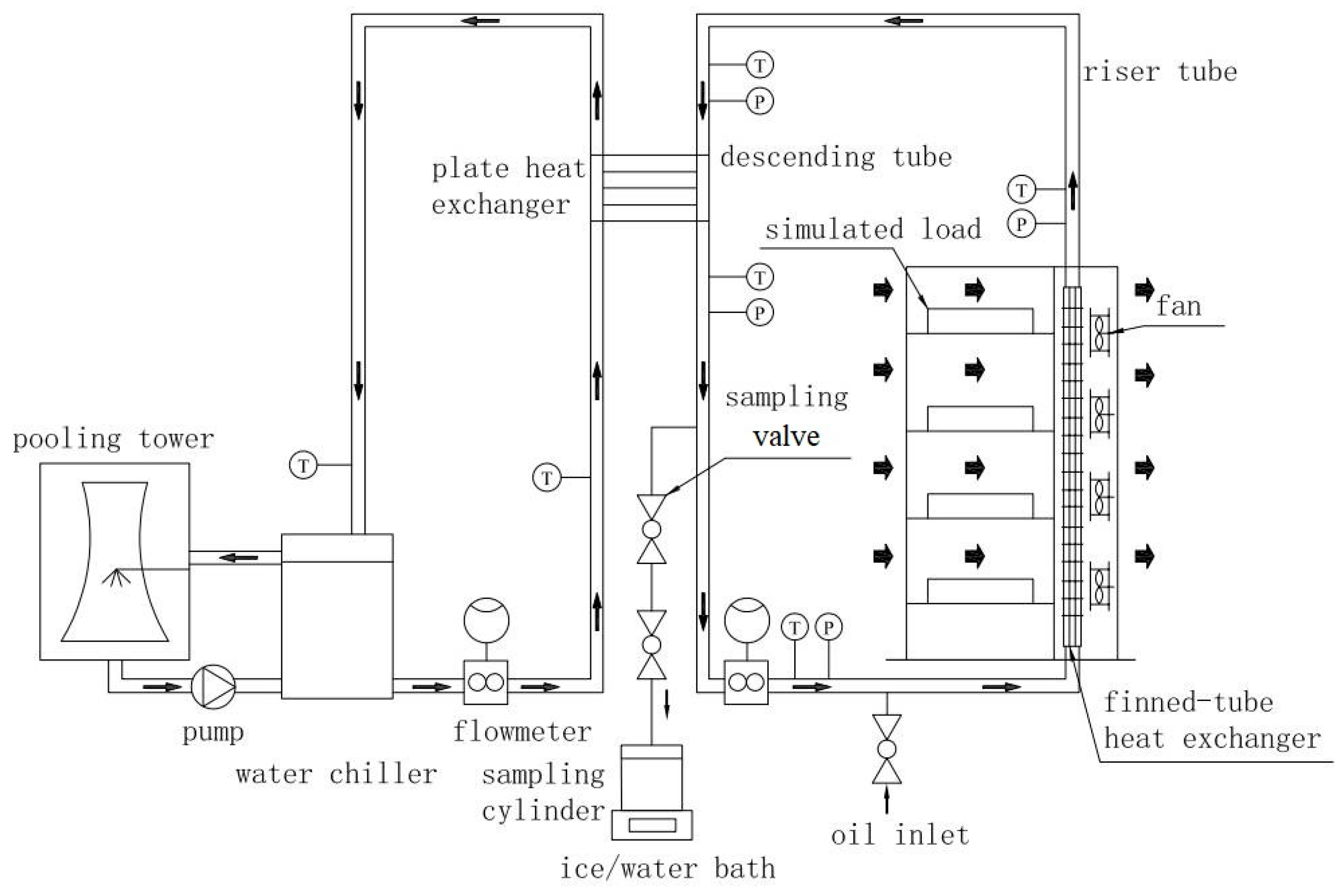
2.1. Experimental System

The flow chart of the test system for a GSHP is depicted in Figure 1. The system is composed of two subsystems: refrigerant loop and cooling water circulation. The refrigerant loop is situated within an air-conditioned room with temperature held at 24.0 ± 1 °C and relative humidity kept at less than 50%. Within the evaporator, the refrigerant absorbs heat from the hot air emanating from the cabinet and then travels through the riser to the condenser. There, it is cooled by the circulating cooling water and subsequently returns to the evaporator via the descending tube, completing the cycle. In the cooling water circulation subsystem, a water chiller provides cold water at a temperature range of 10 to 20 °C to the condenser. The flow rate is modulated by an inverter-driven pump. The evaporator, a finned tube heat exchanger, is mounted on the back plate of the cabinet with dimensions of 1.2 m in length, 0.6 m in width, and 2.2 m in height. The condenser, a plate heat exchanger, is installed on the wall, with its base positioned 0.6 m above the evaporator’s top edge. Detailed structural parameters for both the condenser and the evaporator are shown in Table 1. The inner diameter of the riser is 17 mm, and its length is 6 m. The inner diameter of the descending tube is 14 mm, and its length is 6.7 m. Both the riser and the descending tube are stainless steel hoses. Four simulated loads, each rated at 2 kW, are evenly distributed in the cabinet to heat the air. Emkarate RL-46H, a polyol ester (POE) oil, is selected as the lubricant. The basic properties of this oil are shown in Table 2.
The refrigerant and the oil are introduced into the system via the inlet, as depicted in Figure 1. The charged amount is determined by weighing. The oil concentration is calculated as follows:
c o i l = m o i l m o i l + m R
where m R is the mass of charged refrigerant, and m o i l is the mass of charged oil.
The filling ratio of the heat pipe is defined as follows:
φ = V f i l l V e v a p
where V f i l l is the liquid volume of charged refrigerant, and V e v a p is the internal volume of the evaporator.
A variety of instruments were employed to monitor and record the parameters. At the inlets and outlets of the evaporator and the condenser, PT100 platinum resistance thermometers (Xiamen Mingcon Instrument Co., Ltd., Xiamen, China) and pressure sensors (Xuan Sheng Instrument Technology Co., Ltd., Suzhou, China) were installed to measure temperature and pressure, respectively. Eight calibrated thermocouples (OMEGA Engineering Co., Ltd., Shanghai, China) are evenly positioned in the front and rear of the evaporator to measure the air temperature. The refrigerant mass flow rate is ascertained using a Coriolis mass flow meter (Micro Motion, Inc., Boulder, CO, USA). The flow rate of cooling water is determined by an electromagnetic flow meter (Shanghai Micro Condition Measurement and Control Technology Co., Ltd., Shanghai, China). The signals of the above-mentioned sensors are acquired by a data acquisition unit, Agilent 34970a (Keysight Technologies, Inc. Beijing, China). The specifications of the primary measuring devices are outlined in Table 3.

2.2. Experimental Procedure

The experimental protocol determining the performance of the heat pipe follows the Code for Data Center Design (GB 50174-2017) [19]. The experiments were carried out under the specific conditions listed in Table 4. Once the system had achieved a stable operating state for a duration exceeding twenty minutes, the oil circulation ratio (OCR) was measured. The recorded parameters were utilized to evaluate the performance of the SHP.
OCR is defined as the ratio of the mass flow rate of the oil to the mass flow rate of the refrigerant–oil mixture. OCR was estimated by the weighing method [20,21]. Its calculation is conducted using the following formula:
O C R = m o i l , 1 + m o i l , 2 m m i x
where m m i x , m o i l , 1 , and m o i l , 2 are determined with the following procedure: (1) the sampling cylinder was vacuumed, weighed, placed in an ice-water bath, and connected to the sampling port; (2) the sampling cylinder was filled with the refrigerant/lubricant mixture by operation of the sampling valve; (3) the weight of the mixture m m i x was determined by weighing; (4) a stainless steel cup with oil absorbent at the mouth was prepared and weighed; (5) the refrigerant/lubricant mixture in the sampling cylinder was transferred to the bottom of the stainless steel cup; (6) the empty sampling cylinder was weighed to determine the oil retention in the cylinder, m o i l , 1 ; (7) the stainless steel cup was weighed after the refrigerant inside it evaporated; thus, the oil retention in the cup, m o i l , 2 , was obtained.

2.3. Experimental Data Processing

As referenced in [22], the measurements on the water side are used to calculate the heat transfer rate:
Q = C w ρ w V w t w o t w i
where C w is water heat capacity, kJ/(kg °C); ρ w is water density, kg/m3; V w is volume flow rate of cooling water, m3/s; t w i is the inlet temperature of cooling water, °C; t w o is the outlet temperature of cooling water, °C.
The heat transfer resistance of the loop heat pipe is calculated as follows:
R = t a i ( t w o + t w i ) / 2 Q
where t a i is the inlet air temperature of the evaporator, °C.
The subcooling degree of the refrigerant at the outlet of the condenser is defined as follows:
t s c = t c s t c o
where t c o is the outlet temperature of the condenser, °C; t c s is the saturated condensation temperature, °C.
The heat transfer situation of the evaporator can be reflected by the superheat degree defined as follows:
t s h = t e o t e s
where t e o is the outlet temperature of the evaporator, °C; t e s is the saturated evaporation temperature, °C.
The relative uncertainties associated with the measurements of heat transfer rate, thermal resistance, oil concentration, and OCR are estimated to be 2.8%, 3.0%, 1.3%, and 9.1%, respectively. These estimations are conducted with the approach recommended by Ding et al. [23].

3. Results and Discussions

The performance of the SHP under an oil-free environment was initially examined. The refrigerant charge and the inlet cooling temperature of the condenser were varied to examine their effects. Two scenarios were identified: one with an adequate refrigerant charge and another with an insufficient charge. Subsequently, the influence of lubricant on the performance in these two scenarios was explored. Discussions about the inherent flow and heat transfer mechanisms and comparison with the existing literature are provided at the end of this section.

3.1. Oil-Free Case

Figure 2 shows the heat transfer performance of the SHP across a range of refrigerant charges and cooling inlet temperatures under the oil-free environment. As the filling ratio increases, the heat transfer rate initially rises and subsequently declines. Specifically, at a cooling water temperature of 16 °C, as the filling ratio is increased from 0.755 to 1.079, the heat transfer rate increases from 4.608 kW to a peak of 6.852 kW, after which it drops to 6.525 kW. The largest heat transfer rate is observed at a filling ratio of 0.971 for all inlet temperatures. In scenarios of insufficient refrigerant charge, the evaporator exhibits a “lack of liquid” phenomenon, characterized by a large ratio of superheat area. When the charge is excessive, the condenser exhibits a “liquid accumulation” phenomenon, marked by a large ratio of subcooling area. The effect of excessive charge varies with inlet temperature of cooling water. A lower inlet temperature results in a more pronounced negative effect. Optimal performance is achieved with a moderate refrigerant charge, which maximizes the two-phase zone ratio of the evaporator. Similar impacts of refrigerant charge on system performance have also been reported by previous studies. For instance, Zou et al. tested four filling ratios of 18.7%, 28.0%, 37.3%, and 46.7% and found that the optimal filling ratio is 37.3% [24].
Figure 3 illustrates the variations in superheat and subcooling of the refrigerant at the inlet and outlet of the evaporator across different filling ratios. Under conditions of insufficient charge (filling ratio = 0.755, 0.863), the superheat of the evaporator outlet consistently exceeds 5 °C, escalating as the cooling water temperature diminishes. A lower filling ratio results in a smaller two-phase zone, and thus a higher superheat. At a filling ratio of 0.971, the superheat at the outlet of the evaporator vanishes for cooling water temperatures above 18 °C. However, if the cooling water temperature is decreased to 10 °C, the outlet superheat soars to 6.95 °C, and the subcooling degree at the evaporator inlet also ascends to over 5 °C, signifying substantial subcooled liquid refrigerant accumulation at the bottom of the evaporator. As the filling ratio ascends further to 1.079, the outlet superheat remains effectively zero with decreasing cooling water temperatures, while the subcooling degree progressively increases, culminating at 6.98 °C. Even with the optimal filling ratio determined through testing, the evaporator still cannot operate in an ideal state, in which a two-phase zone occupies 100% of the heat transfer area.

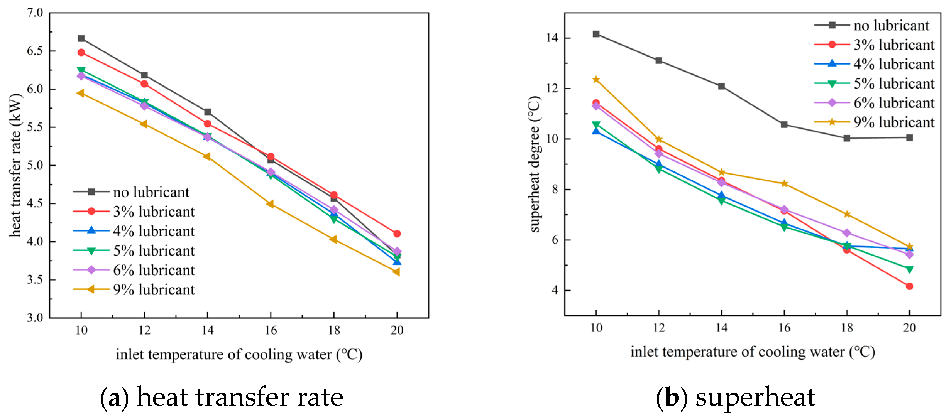
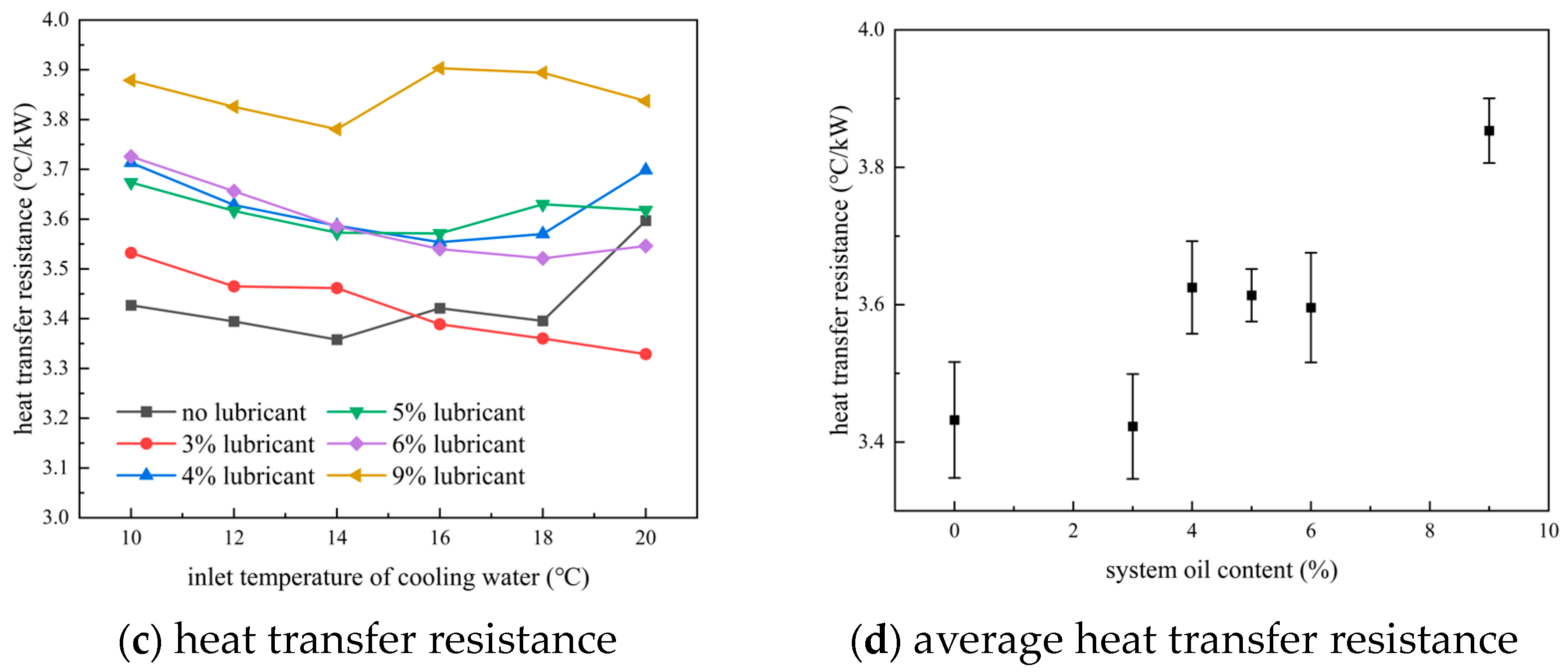
3.2. Lubricant-Influenced Performance with Sufficient Refrigerant Charge

Through the above research, it was found that the SHP attains its best heat transfer performance at a filling ratio of 0.971. Under this condition, 3% lubricant was added into the SHP. After the system reached a stable operating state, the OCR was determined to be approximately 0.29%. The heat transfer rate, superheating/subcooling conditions, and heat transfer resistance of the SHP before and after the lubricant addition are shown in Figure 4a, Figure 4b and Figure 4c, respectively. The heat transfer resistance is presented as an average value, encompassing a range of cooling water temperatures from 12 °C to 20 °C. As depicted in Figure 4a,c, the addition of lubricant leads to a reduction in the heat transfer rate and a corresponding increase in heat transfer resistance by 3.86%. Figure 4b shows the specific impacts of lubricant addition on the superheat at the evaporator outlet and the subcooling at the condenser outlet. As the superheat and subcooling zones of the evaporator expand, the area of the two-phase zone is reduced accordingly.
In the case of overcharging, specifically at a filling ratio of 1.079, the addition of 3% lubricant resulted in an OCR of approximately 0.11%. As illustrated in Figure 4c, the presence of lubricant elevates the heat transfer resistance of the SHP by 10.79%, indicating a significant negative impact. This increase in heat transfer resistance, when compared with the scenario of optimal charge, demonstrates a more pronounced deterioration in heat transfer performance.

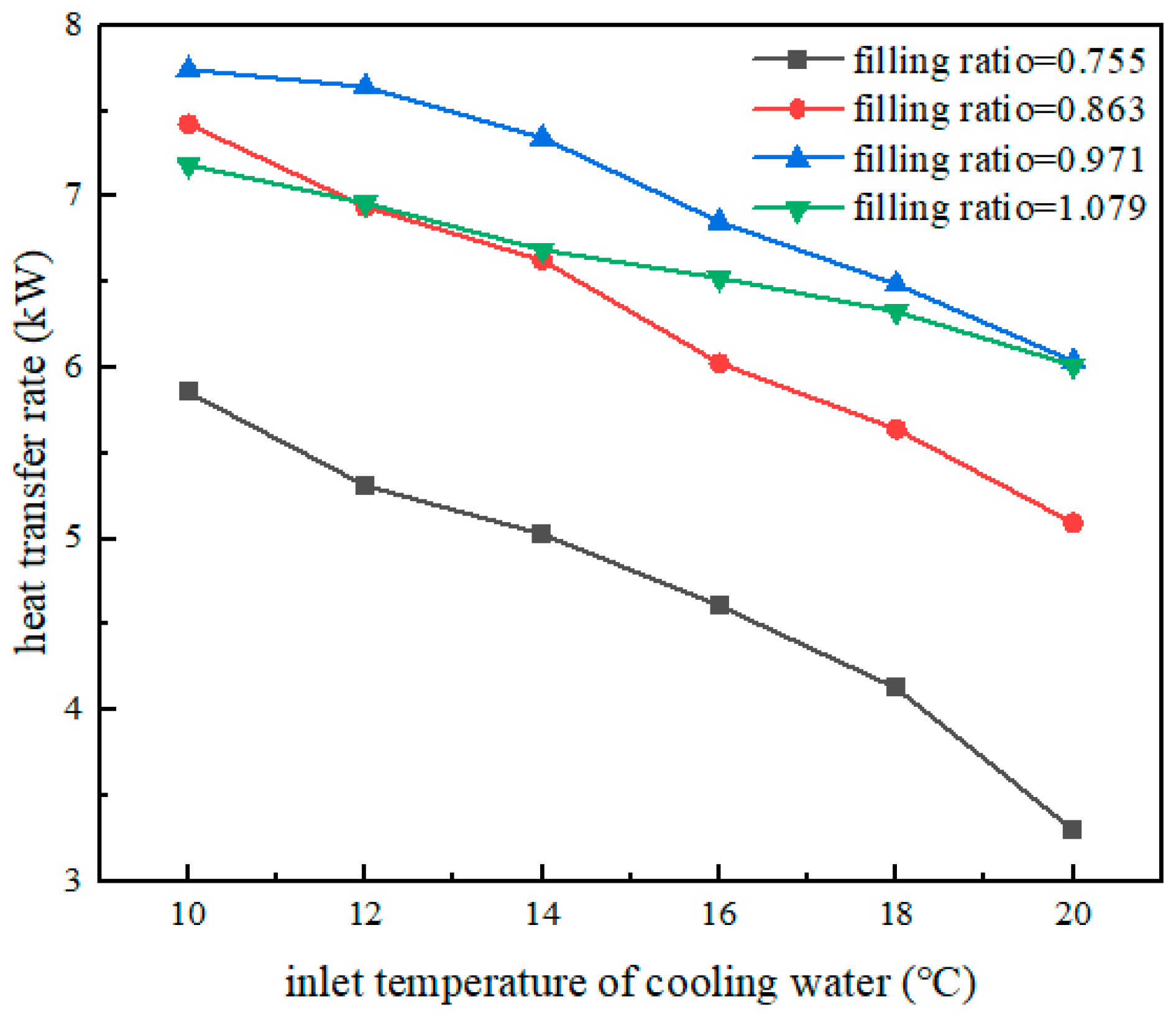
3.3. Performance with Lubricant and Insufficient Refrigerant Charge

In this scenario, tests were carried out at a refrigerant charge of 3.5 kg or a filling ratio of 0.755. While the lubricant concentration varied from 3% to 9%, the measured OCR consistently fluctuated between 0.02 and 0.11%. This observation suggests that a significant portion of the lubricating oil remained within the liquid line and at the bottom of the evaporator, thereby not engaging in the circulation process. Consequently, this retention of lubricant adversely impacted the heat exchange efficiency of the evaporator.
Figure 5 shows the effects of lubricant on SHP performances. As can be seen from Figure 5a, the heat transfer rate diminishes with an increase in inlet cooling water temperature. The heat transfer rate is the highest in the absence of lubricant when the inlet temperature of cooling water is lower than 16 °C. A 3% lubricant concentration enhances the heat transfer in the conditions of high inlet temperature of cooling water; however, even higher concentrations result in a detrimental effect. The effect of lubricant on SHP performance is further evident in superheat at the evaporator exit, as shown in Figure 5b. The heat transfer resistance varies with both lubricant concentration and inlet temperature, as shown in Figure 5c. Figure 5d shows the heat transfer resistance averaged over the whole temperature range investigated. Compared to an oil-free scenario, a 3% lubricant concentration leads to a 0.20% reduction in average resistance. In contrast, 4%, 5%, and 6% lubricant concentrations led to a similar increase in heat transfer resistance, averaging at approximately 5.27%, with individual increases of 5.65%, 5.34%, and 4.83% respectively. A 9% lubricant concentration caused a significant rise of 12.32% in heat transfer resistance.

3.4. Discussions

According to the above experimental results, it can be found that the influence of lubricant on the heat transfer performance depends on both refrigerant charge and lubricant concentration. Specifically, when the refrigerant charge is sufficient, even more than the optimal amount, the addition of lubricant will reduce the heat transfer performance. This is mainly due to the fact that the oil film formed by the lubricant will raise the thermal resistance and hinder heat transfer. On the other hand, the high viscosity and mass transfer resistance of the refrigerant/lubricant mixture will also impair the flow boiling, resulting in an increase in thermal resistance and a decrease in heat transfer rate. When the refrigerant charge is insufficient, a small amount of lubricant can improve the heat transfer performance to a certain extent. Under this situation, the addition of lubricant increases the viscosity and surface tension of the mixture, accelerates the formation of circulation, increases the wetting area and the evaporation area, and thus enhances the heat transfer performance. Furthermore, the foaming of the oil may also be an important cause of increased wetting of the heat transfer surface. Although the oil film can also hinder heat transfer under this situation, its effect is not dominant. Similar mechanisms have been reported in other studies about the effects of lubricants on heat transfer [25,26].
The OCR of the GSHP is between 0.02% and 0.11%, which is much lower than that of a vapor compression system, where the OCR typically lies between 0.25% and 0.29% [21]. This is attributed to the low mass flux of the GSHP. In this study, it varies between 8.7 and 16.6 kg/m2s, much less than that in the channel of a vapor compression system, usually exceeding 100 kg/m2s.
In a study conducted by Zhang et al. [18], the viscosity of the lubricant (FS120R) at 40 °C was 124.6 mm2/s, and the mass flow rate of the refrigerant was regulated by a valve placed on the gas line. Their study revealed that when the working condition of the SHP is good, without superheating in the evaporator, adding oil will be harmful to heat transfer performance. Conversely, when the working condition of the SHP is poor, with obvious superheating in the evaporator, adding oil will be beneficial to heat transfer performance. Although there are differences in the types of lubricants, evaporators, and condensers between their study and ours, their findings have common points with our findings: when the SHP works in good condition, with almost no superheat at the evaporator exit, the addition of lubricant will deteriorate its heat transfer performance.

4. Conclusions

In a directly coupled system of a GSHP with vapor compression refrigeration, the lubricant of the refrigeration compressor can influence the performance of the GSHP. Through comparative experiments, the quantitative effects of a POE oil, Emkarate RL-46H, on the performance of a commercial-scale GSHP which employs R134a as working fluid were investigated. The following conclusions can be drawn:
Most of the lubricant tends to accumulate in the liquid line and at the bottom of the evaporator. For the selected refrigerant/lubricant pair, R134a/Emkarate RL-46H, the OCR maintains a low level, varying between 0.02% and 0.11%, even at a lubricant concentration of up to 9%.
The impacts of the lubricant on the heat transfer resistance of GSHP depend on both the refrigerant charge and the lubricant concentration. With sufficient refrigerant charge, a 3% lubricant concentration increases the heat transfer resistance of SHP by 3.86%. Conversely, when the charge is insufficient, a 3% lubricant concentration reduces the heat transfer resistance of SHP by 0.20%. Additionally, 4%, 5%, 6% lubricant concentrations increase the heat transfer resistance similarly, averaging approximately 5.27%. A 9% lubricant concentration leads to an increase in heat transfer resistance by 12.32%.
These findings could provide valuable insights for the design and operation of directly coupled systems of GSHPs with vapor compression refrigeration.

Author Contributions

Study conception and design: S.Z. and Y.R.; experiment: W.H. and B.D.; literature, analysis and interpretation of results: W.S. and S.Z.; draft manuscript preparation: Y.R., S.Z., and Z.M. All authors have read and agreed to the published version of the manuscript.

Funding

This work was supported by the archeological artifact protection technology project of Zhejiang Province (NO2021013).

Data Availability Statement

The original contributions presented in the study are included in the article; further inquiries can be directed to the corresponding author.

Conflicts of Interest

The authors Yiming Rongyang, Weitao Su and Bowen Du were employed by the company Power China Huadong Engineering Corporation Limited. The remaining authors declare that the research was conducted in the absence of any commercial or financial relationships that could be construed as a potential conflict of interest.

References

  1. Alkrush, A.A.; Salem, M.S.; Abdelrehim, O.; Hegazi, A.A. Data centers cooling: A critical review of techniques, challenges, and energy saving solutions. Int. J. Refrig. 2024, 160, 246–262. [Google Scholar] [CrossRef]
  2. Xu, S.; Zhang, H.; Wang, Z. Thermal Management and Energy Consumption in Air, Liquid, and Free Cooling Systems for Data Centers: A Review. Energies 2023, 16, 1279. [Google Scholar] [CrossRef]
  3. Zhu, H.; Zhang, D.; Goh, H.H.; Wang, S.; Ahmad, T.; Mao, D.; Liu, T.; Zhao, H.; Wu, T. Future data center energy-conservation and emission-reduction technologies in the context of smart and low-carbon city construction. Sustain. Cities Soc. 2023, 89, 104322. [Google Scholar] [CrossRef]
  4. Wang, X.; Wen, Q.; Yang, J.; Xiang, J.; Wang, Z.; Weng, C.; Chen, F.; Zheng, S. A review on data centre cooling system using heat pipe technology. Sustain. Comput. Inform. Syst. 2022, 35, 100774. [Google Scholar] [CrossRef]
  5. Tong, Z.; Han, Z.; Fang, C.; Wen, X. Two-phase thermosyphon loop with different working fluids used in data centers. Int. J. Heat Mass Transf. 2023, 214, 124393. [Google Scholar] [CrossRef]
  6. Cao, J.; Zheng, Z.; Asim, M.; Hu, M.; Wang, Q.; Su, Y.; Pei, G.; Leung, M.K. A review on independent and integrated/coupled two-phase loop thermosyphons. Appl. Energy 2020, 280, 115885. [Google Scholar] [CrossRef]
  7. Zhang, H.; Shao, S.; Tian, C.; Zhang, K. A review on thermosyphon and its integrated system with vapor compression for free cooling of data centers. Renew. Sustain. Energy Rev. 2018, 81, 789–798. [Google Scholar] [CrossRef]
  8. Okazaki, T.; Seshimo, Y. Cooling System Using Natural Circulation for Air Conditioning. Trans. Jpn. Soc. Refrig. Air Cond. Eng. 2008, 25, 239–251. [Google Scholar]
  9. Han, L.; Shi, W.; Wang, B.; Zhang, P.; Li, X. Energy consumption model of integrated air conditioner with thermosyphon in mobile phone base station. Int. J. Refrig. 2014, 40, 1–10. [Google Scholar] [CrossRef]
  10. Zhang, H.; Shao, S.; Zou, H.; Tian, C. Performance analysis on hybrid system of thermosyphon free cooling and vapor compression refrigeration for data centers in different climate zones of China. Energy Procedia 2014, 61, 428–431. [Google Scholar] [CrossRef]
  11. Wang, Z.; Zhang, X.; Li, Z.; Luo, M. Analysis on energy efficiency of an integrated heat pipe system in data centers. Appl. Therm. Eng. 2015, 90, 937–944. [Google Scholar] [CrossRef]
  12. Lamptey, N.B.; Anka, S.K.; Lee, K.H.; Cho, Y.; Choi, J.W.; Choi, J.M. Comparative energy analysis of cooling energy performance between conventional and hybrid air source internet data center cooling system. Energy Build. 2024, 302, 113759. [Google Scholar] [CrossRef]
  13. Meng, F.; Zhang, Q.; Lin, Y.; Zou, S.; Fu, J.; Liu, B.; Wang, W.; Ma, X.; Du, S. Field study on the performance of a thermosyphon and mechanical refrigeration hybrid cooling system in a 5G telecommunication base station. Energy 2022, 252, 123744. [Google Scholar] [CrossRef]
  14. Zhang, H.; Shao, S.; Xu, H.; Zou, H.; Tang, M.; Tian, C. Simulation on the performance and free cooling potential of the thermosyphon mode in an integrated system of mechanical refrigeration and thermosyphon. Appl. Energy 2017, 185, 1604–1612. [Google Scholar] [CrossRef]
  15. He, Z.; Xi, H.; Ding, T.; Wang, J.; Li, Z. Energy efficiency optimization of an integrated heat pipe cooling system in data center based on genetic algorithm. Appl. Therm. Eng. 2021, 182, 115800. [Google Scholar] [CrossRef]
  16. Meng, F.; Zhang, Q.; Zou, S.; Zhu, X.; Liu, L.; Chen, S. Operating parameters optimization of a thermosyphon and compressor system used in 5G TBS. Appl. Therm. Eng. 2024, 241, 122331. [Google Scholar] [CrossRef]
  17. Fu, R.; He, Z.; Zhang, X. Life cycle cost based optimization design method for an integrated cooling system with multi-operating modes. Appl. Therm. Eng. 2018, 140, 432–441. [Google Scholar] [CrossRef]
  18. Zhang, P.; Shi, W.; Li, X.; Wang, B. Effect of lubricating oil on the performance of two-phase natural circulation. In Proceedings of the 13th National Conference on Refrigerator, Air Conditioner and Compressor, Foshan, China, 9–10 December 2016. (In Chinese). [Google Scholar]
  19. GB 50174-2017; Code for Data Center Design. Ministry of Housing and Urban-Rural Development of the People’s Republic of China: Beijing, China, 2017.
  20. GB/T 5773-2016; Test Mothod for the Performance of Displacement Refrigeration Compressor. General Administration of Quality Supervision, Inspection and Quarantine of the People’s Republic of China: Beijing, China, 2016.
  21. Li, W.; Hrnjak, P. Transient refrigerant and oil distribution in a residential heat pump water heater system: Experiments and model. Int. J. Refrig. 2021, 129, 184–193. [Google Scholar] [CrossRef]
  22. Zhang, P.; Shi, W.; Li, X.; Wang, B.; Zhang, G. A performance evaluation index for two-phase thermosyphon loop used in HVAC systems. Appl. Therm. Eng. 2018, 131, 825–836. [Google Scholar] [CrossRef]
  23. Ding, T.; He, Z.; Hao, T.; Li, Z. Application of separated heat pipe system in data center cooling. Appl. Therm. Eng. 2016, 109, 207–216. [Google Scholar] [CrossRef]
  24. Zou, S.; Zhang, Q.; Yue, C.; Wang, J.; Du, S. Study on the performance and free cooling potential of a R32 loop thermosyphon system used in data center. Energy Build. 2022, 256, 111682. [Google Scholar] [CrossRef]
  25. Shen, B.; Groll, E.A. Review article: A critical review of the influence of lubricants on the heat transfer and pressure drop of refrigerants, Part I: Lubricant influence on pool and flow boiling. HVACR Res. 2005, 11, 341–359. [Google Scholar] [CrossRef]
  26. Shen, B.; Groll, E.A. A critical review of the influence of lubricants on the heat transfer and pressure drop of refrigerants—Part II: Lubricant influence on condensation and pressure drop. HVACR Res. 2005, 11, 511–526. [Google Scholar] [CrossRef]
Figure 1. Flow chart of the performance test system for gravity-assisted separated heat pipe.
Energies 17 03772 g001
Figure 2. SHP performances under the oil-free environment.
Energies 17 03772 g002
Figure 3. SHP subcooling and superheat under the oil-free environment.
Energies 17 03772 g003
Figure 4. Comparison of SHP performances: oil-free case vs. 3% lubricant case.
Energies 17 03772 g004aEnergies 17 03772 g004b
Figure 5. Impacts of lubricant on SHP performance for the case of insufficient charge.
Energies 17 03772 g005aEnergies 17 03772 g005b
Table 1. Structure parameters of the evaporator and the condenser.
Structure Parameters of the EvaporatorValueStructure Parameters of the CondenserValue
Outer diameter, mm7Length of the plate, mm525
Tube wall thickness. mm0.24Width of the plate, mm107
Fin thickness, mm0.11Chevron angle, °65
Space between neighbored fins, mm1.5Thickness of the plate, mm0.4
Space between neighbored columns, mm21Pitch of the chevron, mm7
Space between neighbored rows, mm18Height of the chevron, mm2
Tube length, mm1800Heat exchange area per plate, m20.5
Column number of tube17Section area for single channel, mm2206
Number of tube rows4Number of plates24
Table 2. Basic properties of Emkarate RL-46H(Lubrizol Southeast Asia (Pte) Ltd., Tanjung Penjuru, Singapore).
PropertiesValue
Viscosity/40 °C mm2⋅s−145.3
Viscosity/100 °C mm2⋅s−17.1
Density/20 °C g⋅cm−30.977
Pour Point/°C−46
Flash Point/°C260
Water Content/ppm<40
Acid Value/mg KOH⋅g−10.02
Table 3. Sensors for the measurement.
ParameterTypeRangePrecision
TemperaturePT100 platinum resistor (Xiamen Mingcon Instrument Co., Ltd., Xiamen, China)−50~500 °C±0.1 °C
PressurePressure transmitter (Xuan Sheng Instrument Technology Co., Ltd., Suzhou, China)0~5 MPa±0.2%
Air velocityHot wire anemometer (Testo SE & Co. KGaA, Shenzhen, China)0~30 m/s±0.1 m/s
Refrigerant mass flow rateCoriolis mass flowmeter (Micro Motion, Inc., Boulder, CO, USA)0~0.378 kg/s±0.2%
Water flow rateElectromagnetic flowmeter (Shanghai Micro Condition Measurement and Control Technology Co., Ltd., Shanghai, China)0~17.671 m3/h±0.2%
Fan powerPower meter (Ningbo Gigh-tech Zone Xincheng Electronics Co., Ltd., Ningbo, China)0~2500 W±0.1%
Oil massBalance (Kunshan Scale Electronic Technology Co., Ltd., Ruian, China)0~500 g1 mg
Refrigerant massBalance (Zhejiang Value Mechanical & Electrical Products Co., Ltd., Hangzhou, China)0~5000 g10 mg
Table 4. Test conditions.
ParameterRange
Refrigerant charge (kg)3.5, 4.0, 4.5, 5.0
Cooling water temperature (°C)10, 12, 14, 16, 18, 20
Lubricant concentration (%)0, 3, 6, 9
Air flow rate of the evaporator (m3/h)3200
Volume flow rate of cooling water (m3/h)1.35
Disclaimer/Publisher’s Note: The statements, opinions and data contained in all publications are solely those of the individual author(s) and contributor(s) and not of MDPI and/or the editor(s). MDPI and/or the editor(s) disclaim responsibility for any injury to people or property resulting from any ideas, methods, instructions or products referred to in the content.

