Abstract
This paper presents a novel hybrid type-2 fuzzy sliding mode control approach for regulating active and reactive power exchanged with the utility grid by a doubly-fed induction generator in a wind energy conversion system. The main objective of this hybridization is to eliminate the steady-state chattering phenomenon inherent in sliding mode control while improving the transient delays caused by type-2 fuzzy controllers. In addition, the proposed control approach has proven to be successful in coping with varying generator parameters and exhibited good reference tracking. An in-depth comparative study with state-of-the-art advanced control techniques is also the focus of the present paper. The comparative study has three objectives, namely: a qualitative comparative study that aims to compare response times and reference tracking capabilities; a quantitative evaluation that takes into account time-integrated performance criteria; and finally, robustness capabilities. The simulation results, carried out in the Matlab/Simulink environment, have demonstrated the effectiveness and best performance of the proposed hybrid type-2 fuzzy sliding mode control with respect to other advanced techniques included in the comparison study.
1. Introduction
The worldwide increase in electricity consumption and the limitation and progressive depletion of fossil resources (oil, gas, coal, etc.), characterized on the one hand by the emission of carbon dioxide and on the other by the risk posed by the proliferation of nuclear power stations, have led to the development of more environmentally friendly renewable energy sources [1,2,3]. Renewable energies such as solar thermal, photovoltaic, wind, biomass, and geothermal energy are gaining more and more penetration in the overall energy production scheme of developed countries as they offer the opportunity to produce clean electricity. Wind energy has been one of the fastest growing renewable sources in the last decade because of the benefits it brings. This source is not considered as a replacement of conventional resources but as a complementary energy source to traditional energies [4,5,6,7].
Despite the presence of the sliding contact system and the larger dimensions, the majority of installed wind turbines come equipped with a doubly-fed induction machine (DFIM). This particular technology enables these turbines to function effectively across a wide range of wind speeds, allowing them to extract the maximum available power corresponding to each specific speed characteristic. The stator circuit of the DFIM is directly interconnected with the grid utility, whereas its rotor circuit is connected to the grid utility through power converters. Due to the relatively low power exchange between the rotor and the grid utility, the cost of these converters is significantly reduced when compared to variable-speed wind turbines relying solely on the stator. Consequently, the DFIM has become the preferred choice for generating high power in the wind energy sector [8,9,10]. The advent of power electronic converters and programmable devices has played a significant role in improving the energy efficiency of wind turbines. These technological advances have enabled the implementation of diverse and more efficient control techniques and the use of appropriate optimization algorithms. As a result, the integration of these control techniques and algorithms has led to minimal disturbances in the utility grid while achieving optimal performance and energy optimization of wind turbines [11,12,13].
The rest of the paper is structured as follows. In the next section, the different component models of the wind energy system are presented. In Section 3, several control algorithms are developed in order to obtain good performance and quality of the electrical energy produced by a variable-speed wind energy conversion system, namely: vector control by means of PI controllers based on the orientation of the stator flux; the second control is based on type-1 fuzzy controllers to eliminate the inadequacy and impotence of PI correctors; the third control is based on the adaptation of type-1 fuzzy controllers to solve parametric variation problems; the fourth control is based on type-2 fuzzy controllers to improve the tracking qualities; the fifth control concerns sliding mode control based on the choice of the sliding surface and the convergence condition to create a suitable control law; and the sixth control is based on the hybridization of sliding mode control and type-1 fuzzy logic to eliminate the main drawback, the chattering phenomenon of the sliding mode. The last control, hybrid type-2 fuzzy sliding control, is presented in order to improve tracking qualities and ensure results with less static error. In the last section, we present a comparative study between the different control laws synthesized in this work in order to highlight the efficiency and robustness of each of them.
2. Modeling and Controlling Each Component of the Wind System
This section deals with individual modeling of the variable-speed wind energy conversion chain. Firstly, the wind turbine is modeled and the associated controls that maximize and limit the power generated at low and high wind speeds are investigated. The model of the DFIG is then presented in the farm reference frame linked to the rotating field. The two-stage voltage source inverter (VSI) feeding the rotor part of the DFIG is also presented in this section. In the last part, the DC part, including a controlled AC-DC rectifier and its control strategy, is modeled.
2.1. Modeling and Control Strategy of the Turbine
In order to match the torque/speed characteristics of the turbine and the generator, and to improve the conversion efficiency regarding energy efficiency and power quality, precise modeling and control techniques are needed for different wind speeds [14,15].
The turbine ensures a kinetic energy transformation of wind into mechanical energy. It is composed of three identical blades, of length RT, fixed to a drive shaft connected to a gearbox having a transformation ratio G. This gearbox is responsible for driving the shaft of the electric generator. Let the wind speed be V crossing a constant surface S. Then, the modeling of this turbine is given by the following equations [14,15,16,17,18,19]:
The torque of the turbine is then determined as follows:
Taking into account the gearbox multiplication effect, its gain is modeled mathematically by the following equations:
We will use two control techniques. One control technique aims to optimize the power harnessed if the wind speed is below the level required to reach the turbine’s rated power. The other approach is to restrict the generated power to match the nominal power when encountering strong wind speeds.
2.1.1. Performance Optimized for Lower Wind Speeds
The main focus of the control strategy in this particular zone is to optimize the captured wind energy. This optimization is achieved by maintaining two vital variables at their optimal values: the calibration angle, denoted as β, and the specific speed, denoted as λ. These variables, βopt and λopt, respectively, ensure the attainment of the maximum power coefficient Cpmax. This control technique is referred to as Maximum Power Point Tracking [18,19,20].
2.1.2. Power Limit Control
Within this zone, the aim is to limit the active power produced to its nominal value. This is achieved by adjusting the pitch angle of the blades, which reduces the power coefficient and effectively limits the converted power [20,21]. To obtain the reference angle βref, the measured (produced) power Pmes is controlled to follow the reference (nominal) power Pnom using a PI-type controller. Figure 1 shows the simulation results of applying the two controls to the turbine.
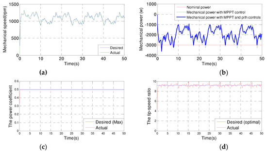
Figure 1.
(a) Mechanical speed; (b) Mechanical power; (c) Power coefficient; (d) Specific speed.
The simulation allowed us to verify the reliability of the two controls. Without speed control for the low wind speeds observed, the specific speed follows the imposed optimal reference and the power coefficient follows the desired maximum power coefficient. By following the pitch control for the high wind speeds we observed, the variation in mechanical speed is adapted to that in the wind, but the blade orientation system strictlylimits the converted power to its nominal value in order to protect the wind turbine well against possible overloads.
2.2. DFIG Modeling
The DFIG is characterized as a highly intricate nonlinear system. To effectively control this type of machine during its various functional states, obtaining an accurate model that replicates its real behavior is necessary. A classical model of the DFIG in the Park reference frame is given by the following expressions [22,23,24,25,26]:
The system is represented in the state space formulation described below:
where:
The constants , , and are defined in the following manner:
2.3. Rotor-Side Converter (RSC) Modeling
Our DFIG-based WECS relies on a static converter to energize the machine’s rotor. The key objectives of this converter are to supply AC voltage to the rotor windings and facilitate control of the injected power to the main utility grid at the stator side.
The converter used in this study is a two-stage three-phase inverter [27,28,29].
The mathematical representation of the RSC is as follows:
2.4. Gid-Side Converter (GSC) Modeling and Control
Several topologies in wind energy conversion systems use a controlled PWM rectifier to ensure DC bus regulation and performa unity power operation [30,31].
The GSC can be divided into three components: the source, the converter, and the output. The model for the output can be represented by the following equations:
The GSC can be governed using a cascade control approach, comprising two internal loops responsible for regulating the phase currents to achieve power factor adjustment, while an external loop takes care of regulating the output voltage. The voltages and powers utilized for this cascade control of the GSC in the Park reference frame are given by the following equations [31,32]:
The expression for the active and reactive powers are as follows:
We pose:
3. Active and Reactive Control
In order to have an optimal yield and a satisfactory power quality of the produced energy by the WECS based on a DFIG, it is essential to employ suitable control techniques. These techniques should enable precise management and regulation of the generated powers. Firstly, the active power will be refined to align with the reference available mechanical power produced at the turbine level, and secondly, in order to uphold a power factor of unity at the stator side and to ensure a satisfactory power quality, the reactive power will be regulated to remain at zero. In this paper, we present seven proposed control strategies to achieve these objectives.
- Vector control using PI controllers;
- Type-1 fuzzy logic control using type-1 fuzzy controllers;
- Type-1 adaptive fuzzy logic control based on type-1 exhaust regulators with adjustment mechanism;
- Type-2 fuzzy logic control based on type-2 exhaust regulators;
- Sliding mode control;
- Hybrid type-1 fuzzy sliding mode control;
- Hybrid type-2 fuzzy sliding mode control.
3.1. Active and Reactive Powers Based on Vector Control
This control technique is among the approaches utilized to optimize the quality of energy produced and injected into the main grid. In this technique, we propose a control algorithm based on the stator flux orientation that links the magnitudes of the stator power and the rotor voltages generated by the inverter. These relationships enable independent control of the active and reactive powers generated at the stator of the DFIG by manipulating the rotor voltages [32,33].
The fundamental concept of this control is similar to that of a separate excitation DC machine. Actually, the active and reactive powers produced at the machine’s stator are independently controlled. The active power is exclusively contingent on the rotor current Irq, whereas the reactive power is uniquely influenced by the current Ird [34,35]. Within this control approach, the machine design ensures that the stator flux in the park frame, aligned with the q-axis, remains at zero, while for the d-axis, it maintains a constant value with minimal influence from the stator resistance Rs. These equations can be simplified as follows [34,35]:
The following equations relate the stator powers to the rotor currents:
The expressions below represent the control voltages obtained, which drive the rotor:
Figure 2 illustrates a block diagram of vector control:
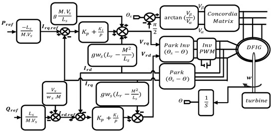
Figure 2.
Block diagram illustrating the vector control structure.
3.2. Active and Reactive Powers Based on Type-1 Fuzzy Logic Control
This control technique is an attractive solution for achieving high performance in a variable-speed WECS based on a DFIG. This nonlinear control approach serves to elevate the caliber of the generated energy. In order to achieve this objective, we will utilize the framework of vector control while substituting the conventional PI regulators with type-1 fuzzy regulators. The input variables for the current loop are as follows:
The current error:
The current error derivative:
Most fuzzy controllers designed for simple single-variable systems consist of the inputs to the fuzzy controller, which are generally the error (the difference between the setpoint and the process output) and its variation (translation of the system dynamics). The majority of controllers developed use the simple scheme proposed by Mamdani [36,37,38].
We have chosen triangular shapes with trapezoidal sides for the membership functions of the fuzzification block, representing the error and its variation, and we have chosen triangular shapes for the membership functions of the defuzzification block, representing the change in the control. Table 1 presents the aggregation of inference rules employed to ascertain the control variable for the current parameter.

Table 1.
Tabulation of the decision rules used by the type-1 fuzzy controller.
Figure 3 illustrates a block diagram of the type-1 fuzzy logic controller.
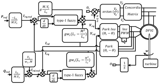
Figure 3.
Block diagram illustrating the structure of a type-1 fuzzy logic controller.
3.3. Active and Reactive Powers Based on Adaptive Type-1 Fuzzy Logic Control
In the field of nonlinear system control, research activities continue to focus on controls based on fuzzy controllers. However, it has become apparent that these controls do not always produce optimal results, especially in the case of nonlinear systems with variable structures. To overcome this problem, controls were developed by adapting the regulators used in these controls for automatic adjustment with the parametric variation of the controlled systems. This innovative approach aims to significantly improve the efficiency of controls applied in variable and complex environments [39,40].
A fuzzy regulator is considered adaptive when it can adjust the error gains and their derivative, or the control gain, in response to parametric variations in the controlled system over time. In this adaptive controller, our main objective is to achieve real-time adaptation of the control gain using an appropriate adjustment mechanism. This approach aims to significantly improve the control performance of our system, particularly when parameter variations occur [40,41,42].
3.4. Active and Reactive Powers Based on Type-2 Fuzzy Logic Control
To improve the performance of our wind power conversion system, we developed a new control technique based on type-2 fuzzy controllers to improve the tracking qualities and still ensure the robustness of our system. This control allows us to keep instantaneous independent control of the active and reactive powers generated by the DFIG in a WECS. To apply this control to our system, we used the same structure of type-1 fuzzy logic control with a change of type-1 fuzzy controllers totype-2 fuzzy controllers [43].
Figure 4 illustrates a block diagram of the type-2 fuzzy logic controller.
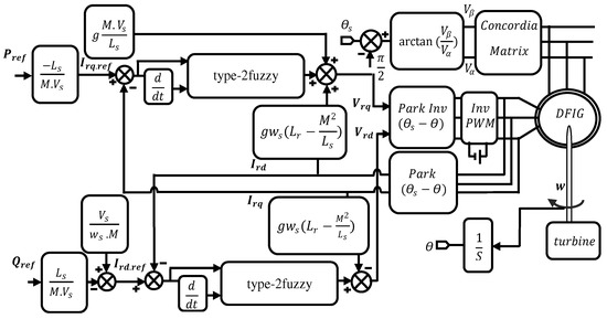
Figure 4.
Block diagram illustrating the structure of a type-2 fuzzy logic controller.
In terms of the form of the membership functions in the fuzzification block, we opted for three Gaussian fuzzy sets to represent the error and its variation. Additionally, for the defuzzification block representing the order variation, we chose five Gaussian fuzzy sets. Table 2 illustrates the compilation of inference rules used to determine the control variable for the current parameter.
Table 2.
Tabulation of the decision rules used by the type-2 fuzzy controller.
3.5. Active and Reactive Powers Based on Sliding Mode Control
The two main drawbacks of vector control are its unsuitability for systems with variable structures and the weakness of classical correctors, which often give less powerful results. To eliminate these drawbacks, we developed a control system that solves these problems by guaranteeing results with less static error, a firm and fast response, and a stable and robust control system. This method is called “sliding mode control” (SMC) and is known for its robustness and simplicity. The primary objective of this control is to achieve independent control of both active and reactive powers generated by a DFIG in a WECS [44].
The basic concept behind this control technique is to drive and maintain the system dynamics (state) within a carefully chosen region, known as the slip plane. A control law is then developed to ensure that the system remains within this region at all times [45,46,47]. Therefore, the relationships between the stator powers and the rotor currents can be expressed as follows:
The derivatives of the reference and measured rotor currents are given by:
The relationship between the active power and the rotor current along the q-axis is directly proportional, whereas the reactive power is also proportional to the rotor current along the d-axis. The equations representing the active and reactive power control surfaces are outlined below:
In order to achieve convergence of the selected variables to their reference values, it is essential that both sliding surfaces reach a value of zero, expressed as follows:
When the convergence conditions are satisfied, the active and reactive powers exhibit exponential convergence towards their respective reference values. To track and maintain these values, it is adequate to ensure that the sliding surface becomes attractive and invariant.
The SMC is realized provided that the Lyaponov attractivity relation is less than zero; that is to say:
3.5.1. Control of the Active Power
The formulation of the control surface and its derivative for the regulation of active power can be expressed as follows:
Replacing the derivatives of the reference and measured rotor currents by their relative expressions gives:
3.5.2. Control of the Reactive Power
The formulation of the control surface and its derivative for the regulation of reactive power can be expressed as follows:
Replacing the derivatives of the reference and measured rotor currents by their relative expressions gives:
Equations (55) and (63) allow the establishment of an SMC block diagram applied to a DFIG, as shown in Figure 5.
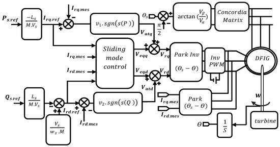
Figure 5.
Block diagram illustratingthe sliding mode control structure.
3.6. Active and Reactive Powers Based on Hybrid Type-1 Fuzzy Sliding Mode Control
This control is an attractive solution to improve the performance of our system and eliminate the major drawback of the previous control, which is the chattering phenomenon produced by the equivalent part. For this purpose, we developed a hybrid control that solves this problem by ensuring high performance results of our variable-speed WECS based on a DFIG. This method is called “hybrid type-1 fuzzy sliding mode control.”
For application of this control to our system, we used the same structure of SMC with a change of the function ‘sgn’ totype-1 fuzzy controllers of the same type (i.e., Mamdani-type controller with seven classes), which had the same membership functions as the controllers already used for the previous type-1 fuzzy control. The difference lay in the normalization gains (scale factors).
Figure 6 illustrates a block diagram of hybrid type-1 fuzzy sliding mode control.
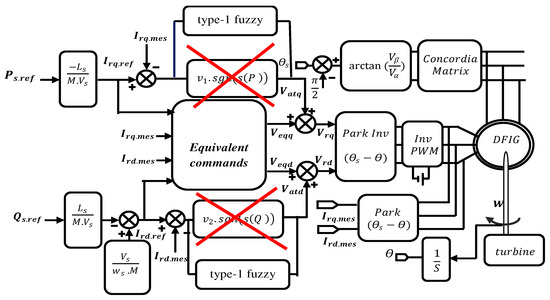
Figure 6.
Block diagram of hybrid type-1 fuzzy sliding mode control.
3.7. Active and Reactive Powers Based on Hybrid Type-2 Fuzzy Sliding Mode Control
Currently, hybrid control is considered of great importance in the field of control of WECS. The interest in this control is to improve the performance of the results obtained by the previous control hybrid type-1 fuzzy sliding mode, which ensures results with less static error, a fixed and fast response, and always eliminates the disadvantage of control by sliding mode, that is, the phenomenon of chattering produced by the equivalent part.
For application of this control to our system, we used the same structure of hybrid type-1 fuzzy sliding mode control with the replacement of type-1 fuzzy controllers by type-2 fuzzy controllers. The membership functions for (e), (Δe), and (Δu) and the rule table in the case of hybrid type-2 fuzzy sliding mode control remained exactly the same as the type-2 fuzzy control. The application of this control was always to control the active and reactive powers generated by our system.
Figure 7 illustrates a block diagram of hybrid type-2 fuzzy sliding mode control.
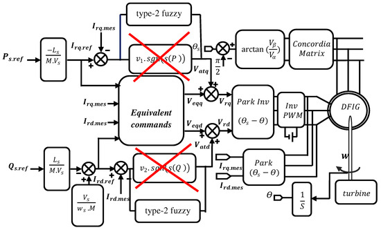
Figure 7.
Block diagram of hybrid type-2 fuzzy sliding mode control.
4. Comparative Study between the Developed Controls
In order to evaluate the different control laws developed for our WECS, we performed a comparative analysis of these different techniques. Three basic approaches were used: qualitative, quantitative, and robustness.
4.1. Qualitative Comparisons
This comparative analysis was based on the examination of simulation outcomes derived from implementing diverse control techniques specifically designed for our system. The evaluation encompassed scenarios with both fixed and variable speeds, allowing us to draw meaningful conclusions.
4.1.1. Qualitative Comparisons for Constant Speed
Figure 2 shows the results of the simulation of the seven controls with a zoom in on the transient points and the setpoint variation for the generator driven at a constant speed of 1440 rpm and subjected to a negative active power step (−3000 W) during the time intervals t = 1 s to t = 3 s. In addition, a positive reactive power step (+1000 VAR) is applied between the time intervals t = 2 s and t = 4 s.
Looking at the simulation results shown in Figure 8, it can be seen that the active and reactive powers are in line with their new reference values for all of the control techniques implemented. However, there are differences in terms of oscillations of the controlled quantities, response time, overshoot, exponential convergence of errors during transient operation, and adaptation to changing setpoints. Among the control methods used, hybrid type-2 fuzzy sliding mode control (H2FLSM.C) has the most favorable values in these aspects, making it the most efficient and effective control approach. It is closely followed by hybrid type-1 fuzzy sliding mode control (H1FLSM.C), sliding mode control (SM.C), type-2 fuzzy logic control (2FL.C), adaptive type-1 fuzzy logic control (A1FL.C), type-1 fuzzy logic control (1FL.C), and finally vector control (V.C).
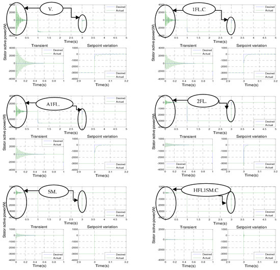
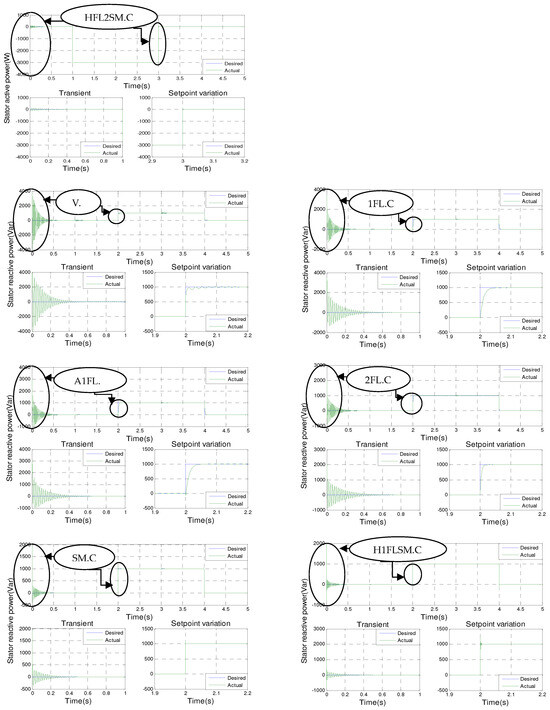
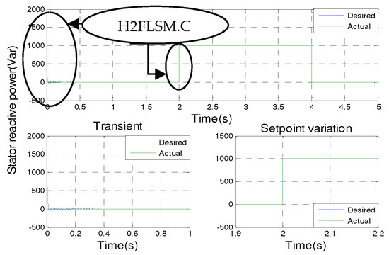
Figure 8.
Active and reactive stator powers for the seven controls with a zoom.
4.1.2. Qualitative Comparisons for Variable Speed
In reality, the generator is directly connected to the grid via the stator, without a converter, and it is controlled via the rotor supply while being driven by a turbine. The reference active power is calculated from the mechanical power produced by the turbine. At the same time, the reference reactive power is controlled to remain at zero, ensuring a unity power factor on the stator side of the DFIG. The simulation runs for a period of 50 s. Figure 9 shows the simulation results of DC bus voltage, current with main voltage, and the active and reactive stator powers with a zoom.
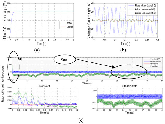
Figure 9.
(a) DC bus voltage−(b) Current with main voltage−(c) Active and reactive stator powers with a zoom.
We noticed that the DC voltage follows the shape of the imposed reference voltage. Moreover, the line currents perfectly follow the shape of the reference currents, which have sinusoidal forms, and which are in phase position with respect to the line voltage. The results obtained demonstrate the efficiency and robustness of the current control in the (d,q) frame of the GSC for harmonic reduction and power factor improvement.
The oscillation generated by the inverter makes it impossible to distinguish between the controls designed for transient and steady states. The simulation results show that the controlled variables converge to their reference values regardless of the type of control used. The response times and overshoots are almost identical for all controllers. As a result, only one result is shown from the different controllers developed.
4.2. Quantitative Comparisons
This evaluation relies on quantifiable simulation results achieved by implementing various control techniques developed for our system (in numbers). For this purpose, we present two quantitative comparisons used in major research works.
4.2.1. Static and Energetic Quantitative Comparison
This evaluation is centered on two factors: the energetic factor J1 and the static factor J2. The former is influenced by the applied control command, while the latter is determined by the resulting error. The energetic criterion J1 and the precision criterion J2 are defined as follows:
Both criteria are calculated for a simulation time of 5 s and power setpoints equal to those given in the simulation conditions. Table 3 illustrates the quantitative static and energetic comparison between the commands developed.
Table 3.
Quantitative static and energetic comparison between the commands developed.
The tabulated simulation results clearly show that type-1 fuzzy logic control has superior performance in terms of minimizing the energy factor. It gives the lowest values of J1 (J1 = 3.1687 × 10⁷) for active power and J1 (J1 = 1.8071 × 10⁷) for reactive power, followed by adaptive type-1 fuzzy control, type-2 fuzzy control, vector control, sliding mode control, hybrid type-2 fuzzy sliding mode control, and hybrid type-1 fuzzy sliding mode control. However, when it comes to the second accuracy criterion, hybrid type-2 fuzzy sliding mode control outperforms the others by minimizing the static criterion. It achieves the lowest values of J2 (J2 = 357.7783) for active power and J2 (J2 = 1.9442 × 10³) for reactive power, followed in order by hybrid type-1 fuzzy sliding mode control, sliding mode control, type-2 fuzzy logic control, type-1 fuzzy logic adaptive control, type-1 fuzzy logic control, and vector control.
4.2.2. Static and Energetic Quantitative Comparison
This test is based on three criteria, which are determined mathematically as follows:
- The integral of the squared error (ISE):
- The integral of the absolute value of the error (IAE):
- The integral of the time multiplied by the absolute value of the error (ITAE):
The criteria are always calculated for a simulation time of Ts = 5 s and power settings equal to those given in the simulation conditions.
The results presented in Table 4 show that hybrid type-2 fuzzy sliding mode control is the best performer in terms of minimizing the criteria ISE, IAE, and ITAE and gives us the lowest values for both active and reactive powers, followed respectively by hybrid type-1 fuzzy sliding mode control, sliding mode control, type-2 fuzzy logic control, adaptive type-1 fuzzy logic control, type-1 fuzzy logic control, and vector control. Table 4 illustrates the quantitative comparisons based on error and time between the developed commands.
Table 4.
Quantitative comparisons based on error and time between the developed commands.
4.3. Robustness Comparisons
Finally, we assessed the robustness of the developed controls by investigating the effect of parametric variations in the DFIG on their performance. It is important to note that, in real systems, these parameters naturally vary due to various physical phenomena, such as inductance saturation and resistance heating. In this particular test, we deliberately varied the following parameters to measure their influence:
The stator and rotor resistances, Rs and Rr, were doubled; the stator and rotor inductances, Ls, Lr, and Msr, were halved; the machine was driven at 1440 rpm; and the parameter changes were implemented at time T = 1.5 s.
The normal state model of the DFIG represented by Equation (20) can be written in matrix form as follows:
With:
To apply the robustness test, the state model is decomposed as follows:
In this comparison, we represented the difference between the results of simulations at the point of parametric changes of the generator to obtain the robustness of the proposed commands. This difference is represented either qualitatively or quantitatively.
4.3.1. Qualitative Robustness Comparison
The basis of this comparison lies in the careful observation and analysis of simulation results at the moment when the generator’s parameters are varied (Figure 10).
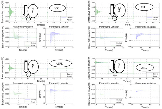
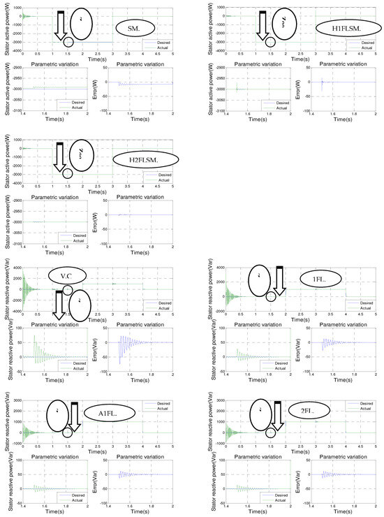
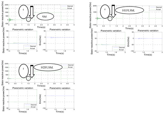
Figure 10.
Stator active power−stator reactive power−error for the seven controls with zoom.
Hybrid type-2 fuzzy sliding mode control is the most effective control, with almost smooth power curves at the points of parametric variation of the DFIG, followed by hybrid type-1 fuzzy sliding mode control, which gives us a low ripple, followed respectively by fuzzy type-2, fuzzy type-1 adaptive, and fuzzy type-1 sliding mode controls, and finally vector control, which gives us a remarkable ripple, exceeding the ripple generated by the other controls. This comparison relies on observing the simulation results generated by executing seven commands on our system at the same time, on the same figure, at the transient point, the setpoint variation, and the parametric variation of the machine. Figure 11 shows the simulation results of active and reactive stator powers for the seven controls in a single zoomed view.
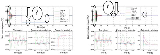
Figure 11.
Active and reactive stator powers for the seven controls in a single zoomed view.
Drawing from the simulation findings, it can be observed that the active and reactive powers for all seven types of control consistently follow their new references. However, it is evident that hybrid type-2 fuzzy sliding mode control outperforms the other control methods in terms of effectiveness and performance, with almost smooth power curves at the points of parametric variation of the machine.
4.3.2. Quantitative Robustness Comparison
This comparison is based on the differences in the figures between the results of simulations at the point of parametric variations of the generator, with the parameter change at time 1.5 s, which serves to emphasize the efficacy of each control method concerning the computation of ISE, IAE, and ITAE, which are calculated in the interval [1.5 s, 2 s].
The results presented in Table 5 clearly show that hybrid type-2 fuzzy sliding mode control is the best performing control from the point of view of minimizing the ISE, IAE, and ITAE criteria for the moment when the generator parameters are varied, followed respectively by hybrid type-1 fuzzy sliding mode control, fuzzy type-2, adaptive fuzzy type-1, and fuzzy type-1 sliding mode controls, and finally vector control. Table 5 illustrates the quantitative comparisons based on error and time between the developed commands at the point of parametric variation.
Table 5.
Quantitative comparisons based on error and time between the developed commands at the point of parametric variation.
5. Conclusions
This article introduces a comparative analysis involvingseven control techniques applied to a WECS, aiming to evaluate their efficiency and performance in the existence or nonexistence of parametric and setpoint variations. The study focuses on three key criteria encompassing both transient and steady-state operation. To conduct this analysis, the system components were accurately modeled, and subsequently, seven control techniques were developed. These techniques aimed to achieve accurate and continuous control of the generated stator power while ensuring stability, rapid tracking, and minimal static error. The obtained results clearly demonstrate that hybrid type-2 fuzzy sliding control outperforms the other control methods, establishing itself as the best performing and most efficient choice for the considered WECS.
Author Contributions
Conceptualization, R.R., A.H. and A.D.; methodology, R.R., A.H. and A.D.; software, R.R., A.H. and A.D.; validation, R.R., A.H. and A.D.; formal analysis, R.R., A.H. and A.D.; investigation, R.R., A.H. and A.D.; resources, R.R., A.H. and A.D.; data curation, R.R., A.H. and A.D.; writing—original draft preparation, R.R., A.H. and A.D.; writing—review and editing, R.R., A.H. and A.D.; visualization, R.R., A.H. and A.D.; supervision, R.R., A.H. and A.D.; project administration, R.R., A.H. and A.D.; funding acquisition, R.R., A.H. and A.D. All authors have read and agreed to the published version of the manuscript.
Funding
This research received no external funding.
Conflicts of Interest
The authors declare no conflict of interest.
References
- Sahri, Y.; Tamalouzt, S.; Belaid, S.L.; Bajaj, M.; Ghoneim, S.S.; Zawbaa, H.M.; Kamel, S. Performance improvement of Hybrid Systembased DFIG-Wind/PV/Batteries connected to DC and AC grid by applying Intelligent Control. Energy Rep. 2023, 9, 2027–2043. [Google Scholar] [CrossRef]
- Falehi, A.D.; Torkaman, H. Promoted supercapacitor control scheme based on robust fractional-order super-twisting slidingmode control for dynamic voltage restorer to enhance FRT and PQ capabilities of DFIG-based wind turbine. J. Energy Storage 2021, 42, 102983. [Google Scholar] [CrossRef]
- Xiong, L.; Li, J.; Li, P.; Huang, S.; Wang, Z.; Wang, J. Event triggered prescribed time convergence sliding mode control of DFIGwith disturbance rejection capability. Int. J. Electr. Power Energy Syst. 2021, 131, 106970. [Google Scholar] [CrossRef]
- Raghavendran, C.R.; Roselyn, J.P.; Sowmmiya, U.; Devaraj, D. Effective power transfer an dreducedorder generalized integrators equence based fault ride through strategy in grid connected DFIG based WECS. Int. J. Electr. Power Energy Syst. 2021, 130, 1–20. [Google Scholar] [CrossRef]
- Raghavendran, C.R.; Roselyn, J.P.; Devaraj, D. Development and performance analysis of intelligent fault ride through controls chemein the dynamic behaviour of grid connected DFIG based wind systems. Energy Rep. 2020, 6, 2560–2576. [Google Scholar] [CrossRef]
- Wang, H.; Liu, Y.; Zhou, B.; Voropai, N.; Cao, G.; Jia, Y.; Barakhtenko, E. Advanced adaptive frequency support scheme for DFIG under cyber uncertainty. Renew. Energy 2020, 161, 98–109. [Google Scholar] [CrossRef]
- Desalegn, B.; Gebeyehu, D.; Tamrat, B. Wind energy conversion technologies and engineering approaches toenhancing wind power generation. Heliyon 2022, 8, 1–21. [Google Scholar] [CrossRef] [PubMed]
- Jaladi, K.K.; Sandhu, K.S. Real-times imulator based hybrid controller of DFIG-WES during grid faults design and analysis. Int. J. Electr. Power Energy Syst. 2020, 116, 105545. [Google Scholar] [CrossRef]
- Jin, J.X.; Yang, R.H.; Zhang, R.T.; Fan, Y.J.; Xie, Q.; Chen, X.Y. Combined low voltage ride through and powers moothing control for DFIG/PMSG hybrid wind energy conversion system employing a SMES-based AC-DC unified power quality conditioner. Int. J. Electr. Power Energy Syst. 2021, 128, 5. [Google Scholar] [CrossRef]
- Naik, K.A.; Gupta, C.P.; Fernandez, E. Design and implementation of intervaltype-2 fuzzy logic- PI based adaptive controller for DFIG based wind energy system. Int. J. Electr. Power Energy Syst. 2020, 115, 7. [Google Scholar] [CrossRef]
- Xiong, L.; Li, J.; Li, P.; Wang, J. High-order sliding mode control of DFIG under unbalanced grid voltage conditions. Int. J. Electr. Power Energy Syst. 2020, 117, 4. [Google Scholar] [CrossRef]
- Adetokun, B.B.; Muriithi, C.M. Impact of integrating large-scale DFIG-based wind energy conversion system on the voltage stability of weak national grids: A case study of the Nigerian power grid. Energy Rep. 2021, 7, 654–666. [Google Scholar] [CrossRef]
- Abolvafaei, M.; Ganjefar, S. Maximum power extraction from wind energy system using homotopy singular perturbation and fast terminal sliding mode method. Renew. Energy 2020, 148, 611–626. [Google Scholar] [CrossRef]
- Soliman, M.A.; Hasanien, H.M.; Al-Durra, A.; Alsaidan, I. A novel adaptive control method for performance enhancement of grid-connected variable-speed wind generators. IEEE Access 2020, 8, 82617–82629. [Google Scholar] [CrossRef]
- González-Hernández, J.G.; Salas-Cabrera, R.; Vázquez-Bautista, R.; Ong-De-La-Cruz, L.M.; Rodríguez-Guillén, J. A novel MPPT PI discrete reverseacting controller for a wind energy conversion system. Renew. Energy 2021, 178, 904–915. [Google Scholar] [CrossRef]
- Pan, L.; Shao, C. Wind energy conversion systems analysis of PMSG on offshore wind turbine using improved SMC and Extended State Observer. Renew. Energy 2020, 161, 149–161. [Google Scholar] [CrossRef]
- Chojaa, H.; Derouich, A.; Chehaidia, S.; Zamzoum, O.; Taoussi, M.; Elouatouat, H. Integral sliding mode control for DFIG based WECS with MPPT based on artificial neural network under a real wind profile. Energy Rep. 2021, 7, 4809–4824. [Google Scholar] [CrossRef]
- Kadri, A.; Marzougui, H.; Aouiti, A.; Bacha, F. Energy management and control strategy for a DFIG wind turbine/fuel cell hybrid system with super capacitor storage system. Energy 2020, 192, 116518. [Google Scholar] [CrossRef]
- Hamid, C.; Derouich, A.; Taoussi, M.; Zamzoum, O.; Hanafi, A. An Improved Performance Variable Speed Wind Turbine Driving a Doubly Fed Induction Generator Using Sliding Mode Strategy. In Proceedings of the 2020 IEEE 2nd InternationalConference on Electronics, Control, Optimization and Computer Science (ICECOCS), Kenitra, Morocco, 2–3 December 2020. [Google Scholar] [CrossRef]
- Mousa, H.H.H.; Youssef, A.-R.; Mohamed, E.E. Hybrid and adaptive sectors P&O MPPT algorithm based wind generationsystem. Renew. Energy 2020, 145, 1412–1429. [Google Scholar] [CrossRef]
- Tadesse, A.B.; Ayele, E.A.; Olonje, A.O. Design and Analysis of Rate Predictive Fractional-Order Sliding Mode Controlle r(RP-FOSMC) for MPPT and Power Regulation of DFIG-based Wind Energy Conversion System (WECS). Energy Rep. 2022, 8, 11751–11768. [Google Scholar] [CrossRef]
- Kelkoul, B.; Boumediene, A. Stability analysis and study between classical sliding mode control (SMC) and super twisting algorithm (STA) for doubly fed induction generator (DFIG) under wind turbine. Energy 2021, 214, 118871. [Google Scholar] [CrossRef]
- Huang, S.; Wu, Q.; Guo, Y.; Rong, F. Optimal active power control based on MPC for DFIG-based wind farm equipped withdistributed energy storage systems. Int. J. Electr. Power Energy Syst. 2019, 113, 154–163. [Google Scholar] [CrossRef]
- Hemmati, R.; Faraji, H.; Beigvand, N.Y. Multi objective control scheme on DFIG wind turbine integrated with energy storage system and FACTS devices: Steady-state and transient operation improvement. Int. J. Electr. Power Energy Syst. 2022, 135, 107519. [Google Scholar] [CrossRef]
- Li, P.; Xiong, L.; Wu, F.; Ma, M.; Wang, J. Sliding mode controller based on feedback linearization for damping of sub synchronous control interaction in DFIG-based wind power plants. Int. J. Electr. Power Energy Syst. 2019, 107, 239–250. [Google Scholar] [CrossRef]
- Soomro, M.A.; Memon, Z.A.; Kumar, M.; Baloch, M.H. Wind energy integration: Dynamic modeling and control of DFIG based on super twisting fractional order terminal sliding mode controller. Energy Rep. 2021, 7, 6031–6043. [Google Scholar] [CrossRef]
- Benzouaoui, A.; Khouidmi, H.; Bessedik, B. Parallel model predictive direct power control of DFIG for wind energy conversion. Int. J. Electr. Power Energy Syst. 2021, 125, 5. [Google Scholar] [CrossRef]
- Zamzoum, O.; Derouich, A.; Motahhir, S.; El Mourabit, Y.; El Ghzizal, A. Performance analysis of a robust adaptive fuzzy logic controller for wind turbine power limitation. J. Clean. Prod. 2020, 265, 121659. [Google Scholar] [CrossRef]
- Rouabhi, R.; Abdessemed, R.; Chouder, A.; Djerioui, A. Power Quality Enhancement of Grid Connected Doubly- Fed Induction Generator Using Sliding Mode Control. Int. Rev. Electr. Eng. 2015, 10, 266–276. [Google Scholar] [CrossRef]
- Acikgoz, H.; Yildiz, C.; Coteli, R.; Dandil, B. DC-link voltage control of three-phase PWM rectifier by using artificial beecolony based type-2 fuzzy neural network. Microprocess. Microsystems 2020, 78, 32. [Google Scholar] [CrossRef]
- Yang, J.; Meng, N. Multi-loop power control strategy of current source PWM rectifier. Energy Rep. 2022, 8, 11675–11682. [Google Scholar] [CrossRef]
- Kou, L.; Liu, C.; Cai, G.-W.; Zhang, Z.; Zhou, J.-N.; Wang, X.-M. Fault diagnosis for three-phase PWM rectifier based ondeep feed for ward network with transient synthetic features. ISA Trans. 2020, 101, 399–407. [Google Scholar] [CrossRef]
- Milles, A.; Merabet, E.; Benbouhenni, H.; Debdouche, N.; Colak, I. Robust control technique for wind turbine system with interval type-2 fuzzy strategy on a dual star induction generator. Energy Rep. 2024, 11, 2715–2736. [Google Scholar] [CrossRef]
- Akhbari, A.; Rahimi, M. Control and stability analysis of DFIG wind system at the load following mode in a DCmicrogridcomprising wind and micro turbine sources and constant power loads. Int. J. Electr. Power Energy Syst. 2020, 117, 105622. [Google Scholar] [CrossRef]
- Belachew, D.; Gebeyehu, D.; Tamrat, B. Evaluating the performances of PI controller (2DOF) under linear and nonlinear operations of DFIG-based WECS. Heliyon 2022, 8, 2e11912. [Google Scholar] [CrossRef]
- Wadawa, B.; Errami, Y.; Obbadi, A.; Sahnoun, S. Robustification of theH∞ controller combined with fuzzy logic andPI&PID-Fd for hybrid control of Wind Energy Conversion System Connected to the Power Grid Based on DFIG. Energy Rep. 2021, 7, 7539–7571. [Google Scholar] [CrossRef]
- Babu, P.S.; Sundarabalan, C.; Balasundar, C.; Krishnan, T.S. Fuzzy logic based optimal tip speed ratio MPPT controller forgrid connected WECS. Mater. Today Proc. 2021, 45, 2544–2550. [Google Scholar] [CrossRef]
- Malar, A.J.G.; Kumar, C.A.; Saravanan, A.G. Iot based sustainable wind green energy for smart cites using fuzzy logic based fractional order darwinian particles warm optimization. Measurement 2020, 166, 108208. [Google Scholar] [CrossRef]
- Tatlicioglu, E.; Yilmaz, B.M.; Savran, A.; Alci, M. Adaptive fuzzy logic withself-adjusting member ship functions basedtracking control of surface vessels. Ocean Eng. 2022, 253, 111129. [Google Scholar] [CrossRef]
- Mazouza, F.; Belkacem, S.; Colak, I.; Drid, S.; Harbouche, Y. Adaptive direct power control for double fed induction generator used in wind turbine. Int. J. Electr. Power Energy Syst. 2019, 114, 105395. [Google Scholar] [CrossRef]
- Fan, Y.; Kang, T. Type-2fuzzyadaptivecontrolforuncertainrobotmanipulatorsystemwithtime-varyingoutputconstraints. In Proceedings of the 2020 Chinese Control and Decision Conference (CCDC), Hefei, China, 22–24 August 2020; IEEE: Piscataway, NJ, USA, 2020; pp. 2430–2435. [Google Scholar] [CrossRef]
- Al-Mahturi, A.; Santoso, F. An Intelligent Control of an Inverted Pendulum Based on an Adaptive IntervalType-2 Fuzzy Inference System. In Proceedings of the 2019 IEEE International Conference on Fuzzy Systems (FUZZ-IEEE), New Orleans, LA, USA, 23–26 June 2019; IEEE: Piscataway, NJ, USA, 2019. [Google Scholar] [CrossRef]
- Raju, S.K.; Pillai, G. Design and real time implementation of type-2 fuzzy vector control for DFIG based wind generators. Renew. Energy 2016, 88, 40–50. [Google Scholar] [CrossRef]
- Hu, L.; Xue, F.; Qin, Z.; Shi, J.; Qiao, W.; Yang, W.; Yang, T. Sliding mode extremumsee king control based on improved invasive weed optimization for MPPT in wind energy conversion system. Appl. Energy 2019, 248, 567–575. [Google Scholar] [CrossRef]
- Kroics, K.; Bumanis, A. BLDCMotorSpeedControlwithDigitalAdaptivePID-FuzzyControllerandReducedHarmonicContent. Energies 2024, 17, 1311. [Google Scholar] [CrossRef]
- Qiu, D.; Dinçer, H.; Yüksel, S.; Ubay, G.G. Multi-Faceted Analysis of Systematic Risk-Based Wind Energy Investment Decisions in E7 Economies Using Modified Hybrid Modeling with I T2 Fuzzy Sets. Energies 2020, 13, 1423. [Google Scholar] [CrossRef]
- Tian, M.-W.; Alattas, K.; El-Sousy, F.; Alanazi, A.; Mohammadzadeh, A.; Tavoosi, J.; Mobayen, S.; Skruch, P. A New ShortTerm Electrical Load Forecasting by Type-2 Fuzzy Neural Networks. Energies 2022, 15, 3034. [Google Scholar] [CrossRef]
Disclaimer/Publisher’s Note: The statements, opinions and data contained in all publications are solely those of the individual author(s) and contributor(s) and not of MDPI and/or the editor(s). MDPI and/or the editor(s) disclaim responsibility for any injury to people or property resulting from any ideas, methods, instructions or products referred to in the content. |
© 2024 by the authors. Licensee MDPI, Basel, Switzerland. This article is an open access article distributed under the terms and conditions of the Creative Commons Attribution (CC BY) license (https://creativecommons.org/licenses/by/4.0/).