Article

Controller Hardware in the Loop Platform for Evaluating Current-Sharing and Hot-Swap in Microgrids

by
Juan Martínez-Nolasco
1,
Víctor Sámano-Ortega
1,*,
Heriberto Rodriguez-Estrada
1,
Mauro Santoyo-Mora
1,
Elias Rodriguez-Segura
2 and
José Zavala-Villalpando
1
1
Departamento de Ingeniería Mecatrónica, Tecnológico Nacional de México/IT de Celaya, Antonio García Cubas 600, Celaya 38010, Mexico
2
Departamento de Ingeniería Eléctrica y Electrónica, Tecnológico Nacional de México/IT de Celaya, Antonio García Cubas 600, Celaya 38010, Mexico
*
Author to whom correspondence should be addressed.
Energies 2024, 17(15), 3803; https://doi.org/10.3390/en17153803
Submission received: 10 July 2024 / Revised: 27 July 2024 / Accepted: 31 July 2024 / Published: 2 August 2024
(This article belongs to the Special Issue Smart Grid and Energy Storage)

Abstract

:
Microgrids have increased in popularity thanks to both the integration of renewable energy resources and their energy distribution capability for remote locations. Moreover, the microgrids, mainly using multiple generators connected in parallel, acquire additional advantages by using both Hot-Swap and Current-Sharing techniques. This paper presents the development of a Hardware in the Loop platform to test Current-Sharing algorithms. It is reinforced that the use of a real-time simulation based on Hardware in the Loop is a viable and cost-effective alternative in the validation of controllers. The platform was developed in a graphical programming environment (LabVIEW 2015) and implemented with NI MyRIO 1900 (National Instruments Corp., Austin, TX, USA) development boards for easier reproducibility. The entire code project is openly available and provided in this paper. A system of photovoltaic energy generators was used to evaluate the performance of the HIL platform. As a result, the platform was able to reproduce a similar behavior to the photovoltaic generator, presenting average mean errors of 0.4 V and 0.2 A in its voltage and current, respectively. Additionally, the platform showed its capability to test Current-Sharing algorithms in the occurrence of Hot-Swap events. This work contributes with a validation tool for energy management systems applied to microgrids.

1. Introduction

In recent years, DC microgrids have increased in popularity as a plausible alternative to both generate and distribute energy in comparison to conventional energy systems. Among the multiple advantages of a DC microgrid (DC-µG), one that stands out is its energy generation using renewable energy resources (RES). This opens the possibility of reducing the dependency on electrical centrals using fossil fuels, thus diminishing the negative impact on the environment. Between the employed RES in a DC-µG, the use of photovoltaic panels (PV) as generators is very common due to both their financial and technical benefits [1,2]. A microgrid (µG) is structured with five key elements interconnected in a common power bus: distributed generators, energy storage devices, an interconnection system with the AC main grid, loads, and a control unit [3]. The power electronic converters (PECs) play a key role inside a DC-µG. The PECs add control and flexibility to the grid since they act as the main interface between the interconnected elements inside the DC-µG and the distribution bus for the connected loads. Moreover, the DC microgrids (DC-µGs) can deliver successfully a power demand in a controlled and stable manner; therefore, they can be considered as an alternative power generation system for remote locations, data centers, and buildings [4].
The operation of a DC-µG requires a hierarchical control based on two main control levels or layers, i.e., a local control (primary layer) and a global or supervisory control (secondary layer) [5,6]. On the one hand, the local control has the main purpose of regulating the distribution bus voltage; this level of control can be enhanced by including strategies such as Hot-Swap (HS) and Current-Sharing (CS) [7]. On the other hand, the supervisory control could integrate a set of secondary controls to minimize oscillations in the voltage bus, or a set of tertiary controls to handle a connection/disconnection to the AC main grid. Additionally, the supervisory control level can include an Energy Management System (EMS), which is expected to achieve ecological, economical, and calendrical goals [8,9]. As stated by the IEC 61970 norm, an EMS is defined as “a computer system comprising a software platform providing essential support services and a set of applications providing the functionality needed for the effective operation of electrical generation and transmission facilities to assure adequate security of energy supply at minimum cost” [10]. Assuredly, the EMS is responsible for guaranteeing a continuous energy supply in the DC-µG. This becomes possible after managing the available energy in the grid among the generation resources, the storage devices, and the AC main grid. To assure an optimal operation of the DC-µG, the EMS must maximize the usage of RES by exploiting their highest efficiency and reducing the energy losses. Following this optimal operation, the EMS can take account of the emitted greenhouse gases by the grid, too [11]. Based on these approaches for the supervisory level, the DC-µG could have multiple state variants during its operation [12]. Consequently, an EMS must determine the optimal power produced by each generation source while it maintains the stability of the DC-µG [13].
A DC-µG can operate in two different modes: connected mode and islanded mode. In the first case, the DC-µG interchanges energy with the AC main grid through a common coupling point. As this interchange is bidirectional, it is possible to maintain a DC bus regulated in cases such as an energy deficit or an energy surplus. In the islanded mode, the DC-µG must maintain an energy balance between its components by the time that the AC main grid is not accessible. Here, the DC-µG management defines as main goals to preserve a regulated setpoint in the DC voltage bus and to couple the energy demand based on the available energetic resources [14]. The islanded DC-µGs, whose RES include PV and wind turbines, present as the best alternative to satisfy the energy demand in remote locations. However, the unpredictability and variable nature of the RES reflects uncertainty during their operation; therefore, an adequate EMS becomes strictly necessary [15]. Above all, the design of EMS for DC-µGs operating in islanded mode (e.g., the development of electric vehicles and energy supply systems for remote locations) has found new challenges in the creation of new environment-friendly technologies. Consequently, the design of EMS for DC-µGs focuses on a wider addition of RES in the electrical systems in a safe, stable, reliable, robust, and coordinated manner [16].
Due to the number of elements composing a DC-µG, as well as its operational configurations, an EMS must be validated before its implementation on the field. The real-time simulation based on Hardware in the Loop (HIL) appears as an affordable, viable, and commonly used technique to both designing and testing DC-µGs. This technique allows the developer to evaluate a wide variety of conditions during the operation of energy systems, the debugging and optimizing of controllers, and the viability analysis of electrical components connected to the system [17,18,19,20]. Thanks to its advantages, the HIL has been recently employed to validate control techniques in the elements forming a µG, as presented by the following authors. First, in [21] is presented the validation of a controller for a µG. Here, the µG is formed by a diesel generator, a PV system, a battery-based storage system, and electric loads. The diesel generator is emulated and connected to the µG with the Power HIL technique; the emulation employs a digital real-time simulator NovaCor from RTDS Technologies. Based on the close correlation between the Power HIL and its real counterpart, the authors conclude that the Power HIL provides flexibility in validation tests for controllers. In [22], a Current-Sharing Controller (CS-C) is proposed to limit the currents in a low-voltage DC-µG that contains a set of PV generators connected in parallel. The controller was validated with a real-time emulator Typhoon HIL 602, which reproduces the behavior of PV arrays, a battery-based storage system, Buck PECs, and the AC main grid. This work concludes that HIL simulations are useful to validate the effectiveness of CS strategies. Similarly, in [23] was employed the real-time emulator Typhoon HIL to simulate an AC-µG with a 5 µs latency. Here, the authors describe a validation of both centralized and decentralized frequency control schemes for an islanded mode operation. Finally, in [24] is described the conversion control of a wind turbine system and its validation with HIL. The wind turbine system is emulated with two Back-To-Back triphasic PECs, where one PEC emulates the grid side, while the other emulates the machine side.
Besides all the inherent advantages in the use of HIL, several commercial platforms are expensive and out of reach for some researchers. To tackle this problem, several proposals have been developed as low-cost alternatives. As an example, in [25] is presented the use of FPGAs to develop HIL simulations, where the analysis of the HIL development included both the numerical data types and the description method. In this work, it is concluded that the development of HIL simulations using a graphical language such as LabVIEW reduces the effort and time for its implementation. With an educative purpose, the authors in [26] present the development of a HIL platform using a dual-core digital signal processor TMS320F28379D (Texas Instruments Incorporated, Dallas, TX, USA) and an Atmega328P microcontroller (Microchip Technology Inc., Chandler, AZ, USA). To demonstrate the helpfulness of this platform, the authors emulate a Buck PEC and a two-container system. Finally, in [27] is described the implementation of a HIL using two DUE Arduino to simulate the control of dynamic systems. One of the Arduinos emulates a dynamic system while the other works as a DAQ and as a controller at the same time. This platform supports the emulation of dynamic systems such as an RLC circuit, a twin rotor MIMO system, and a microgrid.
Usually, a DC-µG must count with a mechanism to monitor the energy demand on the grid while it has more than one generation system. This guarantees a proportional distribution of the energy demand. In fact, this mechanism can be included as part of the EMS and can be designed to cover the energy demand under diverse circumstances. This accomplishment becomes possible as the EMS considers the energy production capabilities by each generation system in the grid. On the one hand, the monitoring mechanism can intercommunicate globally all the generation systems. Consequently, the EMS also performs global actions to accomplish with the energy demand in the grid. On the other hand, the monitoring mechanism can be coupled to each generation system to be locally controlled. In this last approach, the generation systems do not depend on a direct communication with the EMS to establish an optimal power output [28]. Generally, a PV is directly connected to a power converter, whose joint action can produce a series of perturbances after being connected/disconnected to the DC bus in the grid. Therefore, it is recommended to implement an HS technique as part of the energy management in a DC-µG that has at least two photovoltaic generators parallelly interconnected [29]. Additionally, the HS improves the DC-µG operation by adding a redundancy in the PEC, which increments the reliability, adds up fault tolerance, increases the system’s flexibility and robustness, and reduces the updating and maintaining times of the grid. Another common strategy for PECs connected in parallel is the CS. This strategy is focused on keeping all the converters contributing with an equitable fraction from the demanded current by the load, while the voltage in the DC bus is always maintained regulated [30]. To maintain equitable output currents from the PECs, the CS-C requires a communication channel between the PECs to monitor their available current [31]. Consequently, the equitable current demand from the PECs avoids a working overload, which results in a longer lifespan of their components, and the system maintains a stability thanks to a well-regulated DC bus. In the literature can be found some works where HS and CS strategies are employed. As an example, in [32] is presented a CS technique based on the injection of an AC signal to the DC bus and a controller. Here, the supplied energy from multiple PECs is regulated based on the induced reactive power by an AC signal. This system was evaluated in the face of HS connections. Similarly, in [33] is proposed a secondary layer that operates based on a consensus scheme, which is applied for a Current-Sharing management for distributed generators connected in parallel; the scheme was validated in the face of HS connections also. In [34] is presented an adaptive droop control approach for CS and voltage regulation in DC-µG applications. A virtual resistor is used to modify the reference voltage on each parallel converter; thus, the shared current error is reduced. The adaptive control approach was tested using a real-time simulator OPAL-RT OP4510, achieving a significative error reduction for different loading conditions. Similarly, in [35] is proposed a consensus algorithm based on a model predictive control for both CS and voltage regulation of a DC-µG. The functionality of the controller was demonstrated with a DC-µG that contained four distributed generators interconnected; the DC-µG allowed for the configuration of the input constraints for each generator. Finally, a multi-bus DC-µG with a novel control scheme is proposed in [36]. The novel scheme considers simultaneously both voltage regulation and CS for the grid. To evaluate the effectiveness of the novel scheme, the authors considered a grid with six distributed generators with six interconnected buses through transmission lines.
The aim of this work is to describe the development of a HIL platform to implement and validate CS algorithms. Particularly, the platform emulates three photovoltaic energy generator modules (PEGM) connected in parallel to a DC bus. Each PEGM was built with a 250 W PV, a DC/DC boost PEC with a PI controller for voltage control, a CS-C, and a switching device to produce an HS effect. In addition to having the PEGM, the DC-µG includes an energy storage system and the interconnectivity with the AC main grid. The management of a DC-µG requires that each of its elements has the capability to commute between different operating modes. For example, a photovoltaic generation system can switch from a Maximum Power Point Tracking (MPPT) mode to a voltage regulation mode in the DC bus, or vice versa. In this work, the proposed CS-C is analyzed assuming that the PEGM regulate the DC bus in the DC-µG. Following this, the inclusion of both CS and HS techniques presents several advantages. Generally, it avoids either the overcharge or inactivity of any PV. Furthermore, it allows the modules to connect/disconnect to the DC bus without causing any disturbance. Finally, it keeps a regulated voltage in the face of load changes. The main objective of this research is to provide a platform which could be useful to validate a CS-C in the face of an HS and before being implemented in an EMS. Nevertheless, other operating modes of the PEGM, such as the MPPT, are still outside of the scope for this work.
To validate the HIL platform, an experiment was conducted under the following conditions: a variable working load and an HS connection/disconnection of the PEGM. As a result, the platform emulated the output voltage and the inductor current of the PEGM with mean absolute errors of 0.4 V and 0.2 A, respectively. No doubt, it was possible to conclude the usefulness of the platform to validate the CS-C.
Admittedly, a CS-C not only contributes with a satisfactory coupling of RES, but also enhances their performance. This enhanced performance is a consequence of a reliable, flexible, and robust CS controller. An additional effect of this enhancement can be seen with the reduction of perturbances in the DC bus. With a technological tool such as a HIL platform, the researcher will be able to identify and to correct failures of a CS algorithm, even before implementing it on the field. It is important to mention that this platform contributes to the development and evaluation of EMS for DC-µG during an islanded mode, i.e., the voltage in the bus exclusively depends on the RES (e.g., a main AC grid shortage, or the absence of the main AC grid in remote locations). The islanded mode becomes a critical state for a DC-µG as it must be reliable and offer resilience to the grid.
The HIL platform was built using the graphical programming language of LabVIEW and NI MyRIO 1900 (National Instruments Corp., Austin, TX, USA) boards. The selection of the programming language was made by considering two key ideas: first, the easiness to be reproduced, even by not-experienced researchers in embedded systems; second, to offer a more economical alternative in comparison to dedicated HIL platforms. The complete set of codes developed for this project is available for the reader to use.
The present work is ordered as follows: Section 2 presents the complete description of the system implemented under the HIL platform. Next, Section 3 shows the proposed methodology to implement the HIL platform. This is followed by the results of the experimental stage, which are presented in Section 4. Finally, Section 5 contains the conclusions and future work.

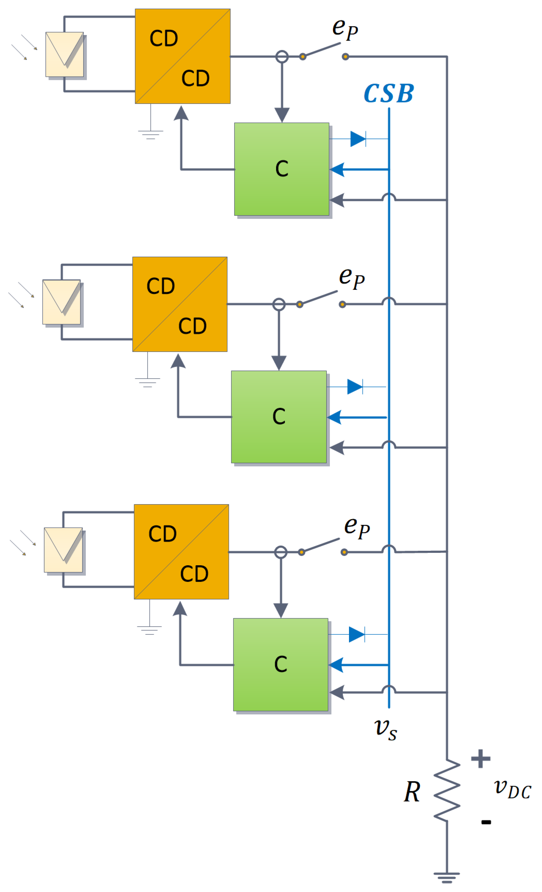
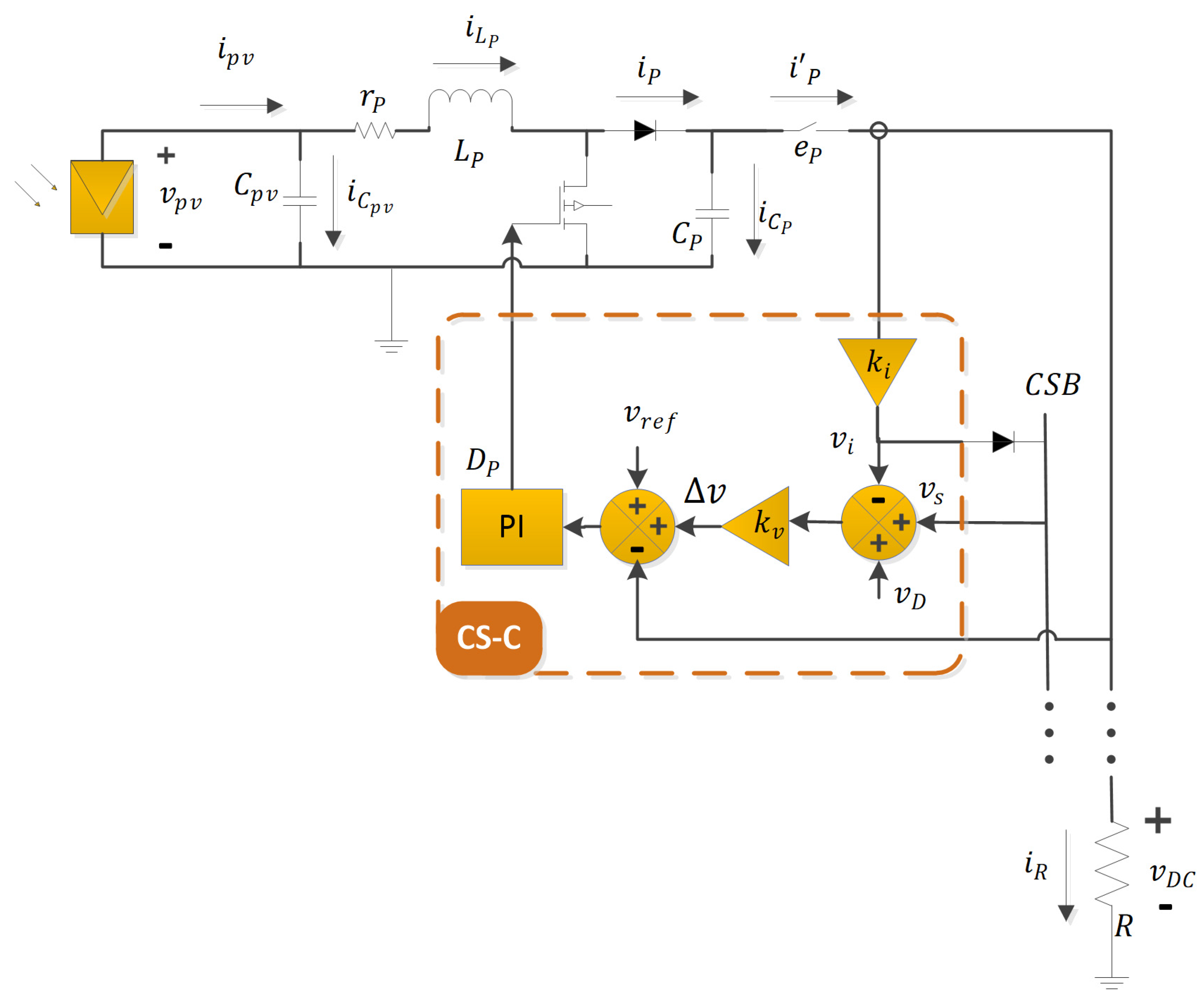
2. System Description

The complete HIL platform, with both the CS-C and the HS, contains three PEGM connected in parallel. The proposed system in this paper provides a DC-µG with a power of 0.75 kW through a 190 V DC bus by using photovoltaic generation. The PV are placed in parallel in the DC-µG; a resistive load is also connected to the grid. This configuration of the DC-µG was used to evaluate both the CS and HS techniques, as well as the performance of the grid during an islanded mode operation. As a future work, it is proposed the addition of more elements such as a battery energy storage system, a wind turbine, and the interconnection with the main AC grid. The forthcoming actions related to the future work proposal is explained with detail in Section 5.
The proposed topology has a measuring line called Current-Sharing bus (CSB), where a voltage set point ( v s ) was established. This set point is employed by an algorithm to manage the current distribution for the connected loads. All the elements of the system can be seen in Figure 1. To evaluate the CS-C under different conditions during an energy demand, a variable resistive load was connected to the DC grid. With this type of load, a starting point was established in the analysis of a DC-µG using HIL; future analyses are expected to consider both inductive and capacitive loads. Additionally, the e P switching devices of each PEGM allows a connection/disconnection to the DC grid to produce the desired HS effect.
As can be seen in Figure 1, each PEGM is composed by a PP, a boost DC/DC PEC, and a controller (represented by the green block C). This controller regulates the output voltage from the PEC and already includes a CS-C. The structure of the PEGM and its elements is showed in detail in Figure 2, whose description is made in the following paragraphs.
The PEGM was modeled based on a 250 W VIRTUS II PV (RENESOLA, Stamford, CT, USA). The main characteristics of this PV include a maximum power output ( P m a x ) of 250 W, a maximum power voltage ( V m a x ) of 30.1 V, a maximum power current ( I m a x ) of 8.31 A, an open-circuit voltage ( V O C ) of 37.4 V, and a short-circuit current ( I S C ) of 8.83 A.
The boost PEC was designed as not isolated and to obtain the highest gain and efficiency from each PV [37]. Accordingly, the design parameters of the boost converter were defined as follows: an input voltage ( V i n ) of 30 V, an output voltage ( V o u t ) of 190 V, a switching frequency ( f s w ) of 130 kHz, and a power output ( P o ) of 250 W. If the PEC receives an input voltage of 30 V to achieve a 190 V output, then it must operate with a gain of 6.33, maintaining a stability under a wide duty cycle condition [38]. Since the DC bus is considered as a large value capacitor with an inherent slow dynamic, the DC bus regulation is viable for this gain. Additionally, the converter was designed to work in a continuous conduction mode, therefore, the converter has a slow response.
The set of PEGM work collaboratively to achieve a voltage regulation in the DC bus. However, each PEGM locally regulates its outputs using a control for voltage regulation and a strategy to obtain a balanced output current. On the one hand, the voltage regulation from the boost converter is made with a PI controller set in a voltage control mode. In similar applications, it is common that the power electronic converters apply an inner loop for a current mode control. Particularly, this type of controller executes the control actions in the PEC on each commutation cycle of the power switching devices. However, the hardware employed for this HIL platform does not tolerate the development of high-switching-frequency models [39]. Then, it is not viable to implement an inner loop with the required latency. Conversely, it is possible to evaluate the proposed CS-C in this work because it has an effect on the outer loop reference in voltage mode to achieve a balanced current distribution, and the voltage dynamics in the DC bus are relatively slower than the current dynamics on each PEC. The present analysis of the CS-C can be extended to similar controllers that have an effect over the outer loop voltage without considering the inner current mode control.
On the other hand, the CS-C monitors the injected current ( i P ) to the power bus, which through the gain k i is converted to a voltage reference ( v i ); v i is transferred through a diode to CSB. As the diodes on each converter are connected to a common bus, the CSB voltage is defined as the maximum voltage v i minus the voltage drop offset in the diode ( v D ), i.e., v s = v i m a x v D . This v s value acts as feedback for the CS-C to be compared versus the present voltage v i on each module. Next, a voltage increment ( v ) is computed after multiplying the k v gain by the voltage difference between the maximum voltage v i and the output voltage v i of each module. The value of v is then added to the PEC reference voltage ( v r e f ). In this way, if a module is supplying less energy than any other module, a positive disturbance is induced to the PEC ( v > 0 ) and has the effect of demanding more energy from this module. On the contrary, when the module is supplying the grid with more energy than any other module, a negative disturbance ( v < 0 ) is induced to the PEC, which is interpreted into a decreasing of the supplied energy by the module. As a result, a balanced energy demand from all the connected modules to the CSB and the power bus is achieved [40]. The CS algorithm is executed continuously on each CS-C. To ease the comprehension of the algorithm, its sequence is shown in the flow chart in Figure 3. Finally, the HS connection is produced by opening and closing the e P switch.

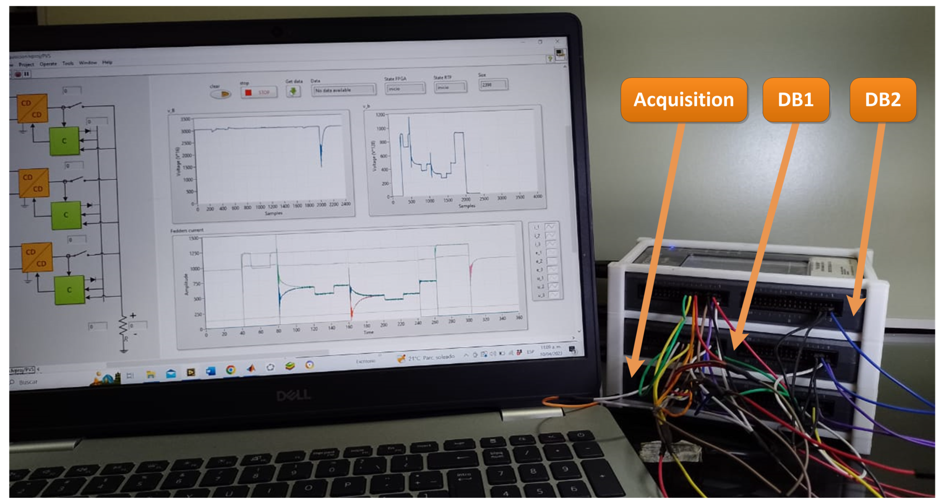
3. HIL Platform Description

Described here is the implemented methodology to both model and embed the elements that integrate the HIL platform described in the previous section.

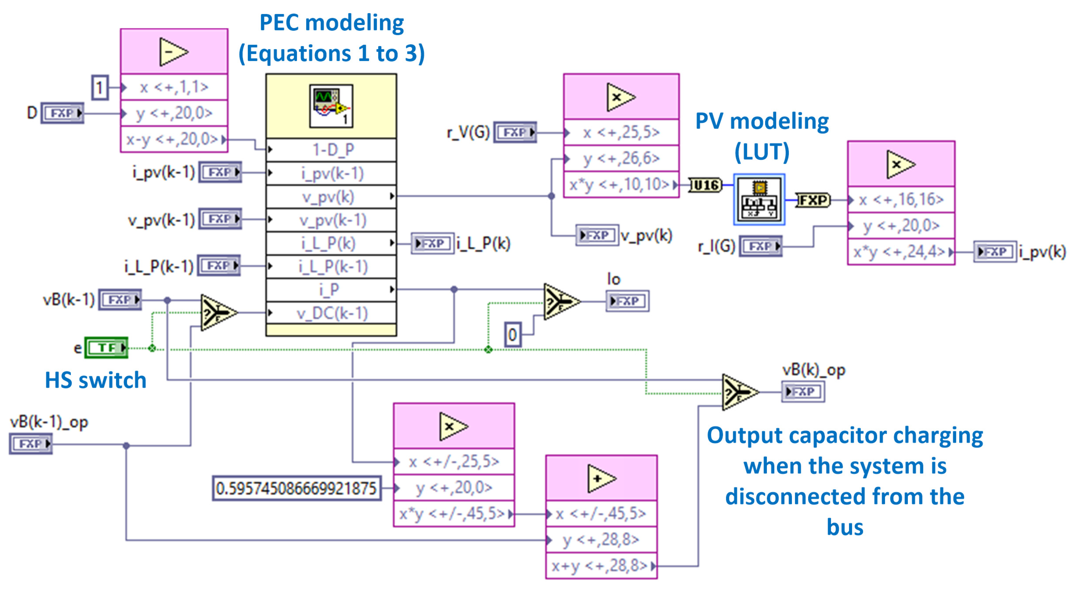
3.1. System Modeling

A PV model was embedded using a 1024-value look-up table (LUT). These values were obtained from a Keysight E4360A (Keysight Technologies, Inc., Santa Rosa, CA, USA) emulator model; a similar approach is described in [41]. This emulator is widely used in research to substitute real PV [42,43,44,45]. The input parameters for this model are the open circuit voltage, the short circuit current, the maximum power point voltage, and the maximum power point current [46]; these values were defined based on the characteristics described in Section 2 for the 250 W VIRTUS II panel.
Similarly, to embed the DC/DC boost PEC, an average model was defined based on the circuit showed in Figure 2 [47] and deriving the discrete Equations (1)–(3). For these equations, T represents the integration period, v p v k is the voltage in the input capacitor ( C p v ), i L P k is the current in the L P inductor, v B is the voltage in the output capacitor ( C P ), and i P k 1 is the current passing through the diode. The HIL platform was implemented in a System on Chip (SoC) that includes a real-time processor (RTP) and an FPGA with a 40 MHz clock system. Particularly, these characteristics allow the device to be considered as a plausible option for developing high-latency applications with low cost; however, it is not viable to develop high-switching-frequency (>20 kHz) models due to the lack of an acceptable resolution [39]. Admittedly, this fact could be a disadvantage in comparison to dedicated HIL platforms. Nevertheless, the low cost of the hardware increases its reproducibility. For this reason, this work makes use of the average model of a converter instead of its commuted model.
v p v k = v p v k 1 + T C p v i p v k 1 T C p v i L P k 1
i L P k = 1 r P T L P i L P k 1 1 L P T L P v D C k 1 + T L P v p v k 1
i P k 1 = 1 D P i L P k 1
Equation (1)–(3) describe the voltage dynamics v p v k in the input capacitor, the current i L P k through the inductor, and the current i L P k passing through the diode, respectively. As all the PECs are interconnected in parallel when their switches are closed, Equation (4) describes the voltage v D C k for the output capacitor, where e i C i is the product of both the output capacitance ( C P ) of each PEC and the switching state e i of the PEC ( e i = 0 when the switch is open, e i = 1 otherwise).
v D C k = T e i C i e i i i ( k 1 ) + 1 T R e i C i v D C ( k 1 )
The PI controller regulating the output voltage in the PEC was embedded based on its discrete model. The model is represented by Equation (5), where P is the proportional gain, I refers to the integral gain, u k is the control signal, and e k is the error signal computed after Equation (6).
u k = u k 1 + P e k + T I P e ( k 1 )
e k = v r e f v D C + v
Finally, the CSB voltage was emulated using Equation (7), where v s is the shared voltage in the bus, k i is the gain for shared current algorithm, m a x i 1 , i 2 , , i n returns the current with the highest value, and v D represents the voltage drop offset in the diode that connects the amplified shared current and the shared bus.
v s = k i m a x i 1 , i 2 , , i n v D
The values of the used constants from Equation (1)–(7) are shown in Table 1.

3.2. Platform Implementation

To execute the evaluation of the proposed system in this work, it was necessary to embed the HIL platform, the set of PEGM, and the voltage dynamics entities of both the power and shared buses. For this purpose, it was required to use two development boards (DB) NI MyRIO 1900 (National Instruments Corp., Austin, TX, USA) These DB have a Xilinx Zynq-7010 SoC (Advanced Micro Devices, Inc., Santa Clara, CA, USA) that includes an RTP and an FPGA with a 40 MHz clock system. Particularly, this FPGA has 28 k logic cells, a 2.1 Mb RAM block, and 80 DSP slices. Under these conditions, each DB is restricted on the number of elements that can be emulated. Thus, the proposed HIL system was emulated with two DB (DB1 and DB2 in Figure 4). The communication between the RTP and the FPGA is through the ARM Advanced Microcontroller Bus Architecture (AMBA) standard. Additionally, the NI MyRIO 1900 (National Instruments Corp., Austin, TX, USA) board has 40 digital input/output (I/O) ports, 8 analog inputs, and 4 analog outputs. The analog inputs use an analog-to-digital converter (ADC) to quantify analog signals. On the contrary, a digital-to-analog converter (DAC) is used to decode digital signals for the analog outputs. Both the ADC and DAC have a 12-bit resolution. The Table 2 contains the main characteristics of the implemented DB for this work.
The connection of the embedded elements in the development boards DB1 and DB2 is shown in Figure 4, as well as the interconnection between the boards. As shown in Figure 4, the PV symbol represents the implemented LUT for a PV, which is connected to a DC/DC block. As it was previously mentioned, the response of the DC/DC block is based on Equations (1)–(3). Similarly, the C block works based on Equation (5) and the CS algorithm described in Section 2. Finally, the v B and v s blocks behave as described by Equation (4) and Equation (7), respectively. Additionally, a third development board (identified as DB3 in Figure 4) was required in order to perform signal acquisition during the evaluation tests. The signal acquisition was set to work with a 0.15 ms sampling rate and to maintain a sampling stage of 300 ms. During this stage, the acquired signals were recorded into FIFO registers. At the end of the sampling stage, the recorded data were transmitted to a PC through the RTP to be displayed and analyzed.
In the FPGA from the DB1 was embedded a PEGM (which contains a PP, a PEC with a controller, and the CS-C) and both blocks v s and v B . Conversely, the FPGA from the DB2 allocated the remaining PGEM, i.e., two additional PGEM. It is important to mention that the signals i 1 , i 2 , and i 3 correspond to the currents on each PEGM and are present as i P in Equation (3). The values of the i P currents, as well as the v B and v s voltages are shared between the boards by using the analog ports. In the case of the switching elements e i , these are enabled/disabled with a set of digital signals, which are generated in the RTP of DB1. The signal for the inner PEGM of DB1 is sent from the RTP to the FPGA directly, using the AMBA protocol. Correspondingly, the signals for the PEGM 2 and 3 are sent using the wired digital I/O pins between DB1 and DB2. The wiring of the development boards DB1 and DB2 as well as the implemented HIL platform can be seen in Figure 5.
To ease the reproduction of the HIL platform presented in this work, it was created with the development environment LabVIEW and high-performance blocks. Figure 6 shows the block diagrams developed to reproduce the PV and PEC models. These diagrams are an example of the algorithm developed for the HIL platform. The complete project and codes for the three DB are openly available in [48].

4. Results

The first step in the validation process for the HIL platform consisted in testing a PEGM individually. This test only took account of the PV, its PEC, and its PI controller without the Current-Sharing algorithm. Using MATLAB and Simulink (R2014a), a software simulation was developed for the continuous model of the PEGM, which was used to compare the accuracy of the HIL platform. Following this, the PEGM was turned on without any load and kept in this condition for 40 ms until the system achieved its stability. Next, a load was connected to demand 10% of the maximum power (25 W) from the PV for another 20 ms. Then, the load was changed to demand from the PV all its maximum power (250 W). For this test, the bus voltage and the inductor current were measured with a 0.15-ms sampling rate. A comparison of the bus voltage response between the PEGM emulation and the PEGM simulation can be seen in Figure 7. Similarly, Figure 8 shows a comparison for the inductor current response. For both Figure 7 and Figure 8, the letter a shows the response of the voltage bus (see Figure 7a) and the inductor current (see Figure 8a) during the whole test. The turn-on response for the bus voltage and the inductor current can be seen in the graphs labeled with the letter b in both Figure 7 and Figure 8. Additionally, the response of the system under a 10% demand of the maximum power corresponds to letter c, where Figure 7c shows the bus voltage response and Figure 8c shows the inductor current response. Lastly, the demand of the maximum power from the PV (labeled as letter d) reflects the voltage bus response in Figure 7d, meanwhile Figure 8d shows the corresponding response for the inductor current. During the test, there were observed mean absolute errors of 0.4 V for the bus voltage and 0.2 A for the inductor current, whereas the maximum absolute error for these variables were 25.3 V and 19.3 A, respectively. Admittedly, these maximum absolute errors are present as oscillations at the beginning of the experiment while the system starts from its initial conditions. These oscillations can be an effect of the inner initialization algorithm in the simulation software. Since these variations in the results are large only during the beginning of the experiment, it is possible to consider them acceptable in the evaluation of the HIL platform performance.
Once the HIL platform demonstrated its capability to emulate a single PEGM, the next step was very clear: evaluate the functionality of the platform with the addition of a CS-C. For this test, first a PEGM was turned on (PEGM 1 connection stage); eventually, at t = 40 ms, a load was connected to demand the maximum power from the PV (Load connection stage), i.e., 250 W. Next, PEGM 2 was connected at t = 80 ms (PEGM 2 connection stage); PEGM 3 was connected (PEGM connection stage) after 80 ms, or t = 160 ms. During this test, the variation on the load considered three stages where the PV was required to work with 70% of the maximum power during 20 ms. The load was variated for the instants t = 50 ms (First load variation stage), t = 120 ms (Second load variation stage), and t = 200 ms (Third load variation stage). Each stage of the described test and the responses of both voltage and current are shown in Figure 9 and Figure 10. On the one hand, Figure 9 shows the values of the three i P currents present in the PEGM, the enabling of the e p switches, and the bus voltage response scaled by a 0.007 factor. On the other hand, Figure 10 shows a detailed response of the bus voltage enclosed by two lines representing the steady state increased by +2% (green line) and decreased by −2% (blue line).

5. Conclusions

After comparing the response of the HIL platform versus the simulation of the continuous model, it was possible to demonstrate the accuracy of the HIL platform to reproduce the behavior of the selected PEGM for this work, where the mean absolute errors during the evaluation were 0.4 V for the bus voltage and 0.2 A for the inductor current. This accuracy allows the asseveration that the developed HIL platform is reliable for the validation of a Current-Sharing algorithm. Therefore, it could be utilized as a tool in the validation of CS-Cs. In the long run, this type of controllers have a direct effect in the enhancement of the attributes of a DC-µG, including its reliability, flexibility, robustness, and the reduction of disturbances.
Even though the objective of this work was to propose a HIL platform to validate any type of CS-C but not a specific CS-C, it was possible to conclude that the implemented controller was effective. This effectiveness was shown with an even distribution of the demanded current and a stable DC bus voltage. Considering a stability band criteria of 2%, it was appreciated with the aid of Figure 10 that the bus voltage maintained its stability under different conditions, e.g., during HS connections and load variations. After a load connection, a single variation above the 2% tolerance band was observed. Consequently, the DC bus suffered a 7.2 V decay, which represents a 3.8% decrease from its nominal value. In the case of low-voltage systems, the IEEE Std 1547-2018 [49] allows a distributed generator to induce a rapid voltage change when it is below 5% from the nominal value. Unquestionably, as the HIL platform had a 3.8% decrease from the nominal value, it accomplishes the standard and, consequently, it maintains the energy quality during the test. The evaluated CS-C in this work corresponds to a conventional droop control. Particularly, a disadvantage of this type of systems is that as the number of connected PEGM increases, the settling time of the system also increases. This is due to the decrease in the perturbance voltage v as the injected current by the PEGM decreases. The state of the art not only introduces some control schemes to solve this problem [32,33,34,35,36], but also offers the addition of functionalities for the CS-C such as the error reduction in the shared current [34], the input constrains setting in the available generation systems [35], and the energy interchange between multiple buses [36]. In a similar way, a low performance in the HIL system was observed due to the use of a single voltage loop for the PI controller in the PEC. However, thanks to the independency of each embedded module in the HIL platform (see Figure 4 and Figure 6), it is possible to modify the implemented controllers separately without affecting any other system (e.g., the PV modules or the PEC). As a future work, it is proposed to employ the developed HIL platform here to evaluate and possibly improve different Current-Sharing algorithms.
The CS-C acts over the voltage reference defined for the local control in the PEC ( v r e f ) by either increasing or decreasing its value. These actions have the purpose of inducing changes in the power that is transferred to the DC bus. To extend the application of the HIL platform to different types of PV modules, or even PECs, it is only necessary to update the characteristics of the modules, or to tune the gains (i.e., k i , k v , P, and I) for the local controller. To update the characteristics of a PV module, it will be necessary to take from its datasheet the corresponding values to the open circuit voltage, the short circuit current, the maximum power point voltage, and the maximum power point current. Next, these values are introduced in a panel emulator, such as the Keysight E4360A (Keysight Technologies, Inc., Santa Rosa, CA, USA), to compute the V-I curve of the desired panel. With this V-I curve, a LUT is built and stored into the memory of a DB to emulate the PV module behavior. In essence, after the application of the updates in both the PV module and the CS-C gains, any user can obtain a new HIL system for its evaluation. No doubt, this represents an advantage of the proposed platform.
The HIL platform introduced here stands out in comparison to similar proposals as it offers excellent performance at a low cost. Additionally, as it uses a graphical programming language, the user can find an easiness in its reproducibility, development, and modification. To be sure, the performance of the developed HIL platform showed a respectable latency versus other low-cost alternatives such as Arduino. For example, presented in [27] is the use of an Arduino DUE to embed a dynamic system. However, this proposal has a lower latency because the board executes a software simulation at the end. On the contrary, by embedding a system in an FPGA, such as the NI MyRIO, the system is emulated in hardware, which results in a better latency. Similarly, presented in [26] is a system working with a software simulation but running in a joint system of a DSP board with an Arduino. Although this system achieves high latency values during the software simulation by using parallel processing, the use of this type of processing requires an advanced C language developer to make use of threads, which can be found in mechanisms such as inter-processor communication. Finally, after comparing the emulation of power electronic converters in a NI MyRIO with LabVIEW versus other alternatives [25], the authors conclude that the duo does not present an adequate efficiency in terms of space and timing. However, it stands out as a powerful alternative in the aspects of design effort and design time.
In essence, the presented platform is useful to evaluate a CS algorithm in the face of HS for a set of PEGM connected in parallel. Then, it is viable to correct a controller designed to regulate a DC bus through renewable energy generators. This correction is necessary in the EMS operation for its application in a DC-µG, as there is a great possibility that the grid depends completely on the RES to operate. However, this operation mode represents only one of the modes existing for a PEGM, so there are some future studies recommended to complement the findings of this work:
  • First is to integrate the HIL platform in a DC-µG that includes more elements of a distinct nature, e.g., a battery energy storage system, a wind turbine, a main grid interconnection, etc. An aspect contributing to this goal includes the validation of the HIL platform not only with a variable load, but also with a single equation describing both the DC bus dynamics and all the connected elements to it.
  • Next is to validate the HIL platform in the face of variations of some other parameters such as the power supplied by the PV, shading of one or various panels, the sudden disconnection of loads from the grid, and the connection of R-L, R-C, and R-L-C loads. In a similar way to the previous goal, a single equation describing the DC bus dynamics and one that is independent from the PEC models will avoid an adjustment in the PEGM after modifying the characteristics and behavior of the connected loads to the bus.
  • Lastly, with the inclusion of additional functions for the PEGM local controllers, e.g., an MPPT, it will be possible to evaluate more operative modes of a DC-µG. As the weather variables have a slower time response, the MPPT demand a lower latency during an emulation than other elements such as the PECs contained in the PEGM. Therefore, this particularity allows the use of the RTP in the SoC to implement MPPT controllers without affecting the performance of other embedded systems.

Author Contributions

Conceptualization, E.R.-S.; methodology, J.M.-N. and V.S.-O.; software, V.S.-O.; validation, J.Z.-V. and H.R.-E.; formal analysis, H.R.-E.; investigation, J.Z.-V. and E.R.-S.; writing—original draft preparation, J.M.-N. and M.S.-M.; writing—review and editing, M.S.-M.; supervision, J.M.-N.; project administration, V.S.-O. All authors have read and agreed to the published version of the manuscript.

Funding

This research received no external funding.

Data Availability Statement

The original data presented in the study are openly available in [48].

Conflicts of Interest

The authors declare no conflicts of interest.

References

  1. Ullah, S.; Haidar, A.M.A.; Zen, H. Assessment of technical and financial benefits of AC and DC microgrids based on solar photovoltaic. Electr. Eng. 2020, 102, 1297–1310. [Google Scholar] [CrossRef]
  2. Datta, U.; Kalam, A.; Shi, J. Hybrid PV–wind renewable energy sources for microgrid application: An overview. In Hybrid-Renewable Energy Systems in Microgrids; Woodhead Publishing: Sawston, UK, 2018; pp. 1–22. [Google Scholar] [CrossRef]
  3. Sood, V.K.; Abdelgawad, H. Microgrids architectures. In Distributed Energy Resources in Microgrids; Academic Press: Cambridge, MA, USA, 2019; pp. 1–31. [Google Scholar] [CrossRef]
  4. Kolluri, R.R.; Mareels, I.; de Hoog, J. Controlling DC microgrids in communities, buildings and data centers. IET Smart Grid 2020, 3, 376–384. [Google Scholar] [CrossRef]
  5. Al-Tameemi, Z.H.A.; Lie, T.T.; Foo, G.; Blaabjerg, F. Optimal Coordinated Control of DC Microgrid Based on Hybrid PSO–GWO Algorithm. Electricity 2022, 3, 346–364. [Google Scholar] [CrossRef]
  6. Yang, Y.; Qin, Y.; Tan, S.-C.; Hui, S.Y.R. Efficient Improvement of Photovoltaic-Battery Systems in Standalone DC Microgrids Using a Local Hierarchical Control for the Battery System. IEEE Trans. Power Electron. 2019, 34, 10796–10807. [Google Scholar] [CrossRef]
  7. Dragičević, T.; Lu, X.; Vasquez, J.C.; Guerrero, J.M. DC Microgrids—Part I: A Review of Control Strategies and Stabilization Techniques. IEEE Trans. Power Electron. 2016, 31, 4876–4891. [Google Scholar] [CrossRef]
  8. Li, Z.; Ren, Z.; Li, H.; Wang, C.; Wang, C.; Hao, L. An Optimal Operation Method of Hybrid AC/DC Distribution Network Under the Goal of Peaking Carbon Dioxide Emissions and Carbon Neutrality. In Proceedings of the 2023 Panda Forum on Power and Energy (PandaFPE), Chengdu, China, 27–30 April 2023; pp. 997–1004. [Google Scholar] [CrossRef]
  9. Tao, P.; Zhang, Y.; Zhao, J. Distributed Energy Storage Cluster Control Method for DC Microgrid Considering Flexibility. Math. Probl. Eng. 2022, 2022, 6761595. [Google Scholar] [CrossRef]
  10. Nojavan, S.; Pashaei-Didani, H.; Mohammadi, A.; Ahmadi-Nezamabad, H. Energy management concept of AC, DC, and hybrid AC/DC microgrids. In Risk-Based Energy Management; Academic Press: Cambridge, MA, USA, 2020; pp. 1–10. [Google Scholar] [CrossRef]
  11. Mostafa, M.H.; Abdel Aleem, S.H.E.; Ali, S.G.; Abdelaziz, A.Y. Energy-management solutions for microgrids. In Distributed Energy Resources in Microgrids; Academic Press: Cambridge, MA, USA, 2019; pp. 483–515. [Google Scholar] [CrossRef]
  12. Merai, M.; Naouar, M.W.; Slama-Belkhodja, I. Coordinated control of multiple Multi-Function Grid connected Converters for power quality improvement in micro-grid applications. In Proceedings of the 2016 7th International Renewable Energy Congress (IREC), Hammamet, Tunisia, 22–24 March 2016; pp. 1–6. [Google Scholar] [CrossRef]
  13. Zahraoui, Y.; Alhamrouni, I.; Mekhilef, S.; Basir Khan, M.R.; Seyedmahmoudian, M.; Stojcevski, A.; Horan, B. Energy management system in microgrids: A comprehensive review. Sustainability 2021, 13, 10492. [Google Scholar] [CrossRef]
  14. Shahgholian, G. A brief review on microgrids: Operation, applications, modeling, and control. Int. Trans. Electr. Energy Syst. 2021, 31, e12885. [Google Scholar] [CrossRef]
  15. Ishraque, M.F.; Shezan, S.A.; Ali, M.M.; Rashid, M.M. Optimization of load dispatch strategies for an islanded microgrid connected with renewable energy sources. Appl. Energy 2021, 292, 116879. [Google Scholar] [CrossRef]
  16. Raya-Armenta, J.M.; Bazmohammadi, N.; Avina-Cervantes, J.G.; Sáez, D.; Vasquez, J.C.; Guerrero, J.M. Energy management system optimization in islanded microgrids: An overview and future trends. Renew. Sustain. Energy Rev. 2021, 149, 111327. [Google Scholar] [CrossRef]
  17. Salcedo, R.; Corbet, E.; Smith, C.; Limpaecher, E.; Rekha, R.; Nowocin, J.; Lauss, G.; Fonkwe, E.; Almeida, M.; Gartner, P.; et al. Banshee distribution network benchmark and prototyping platform for hardware-in-the-loop integration of microgrid and device controllers. J. Eng. 2019, 2019, 5365–5373. [Google Scholar] [CrossRef]
  18. AhmadiAhangar, R.; Rosin, A.; Niaki, A.N.; Palu, I.; Korõtko, T. A review on real-time simulation and analysis methods of microgrids. Int. Trans. Electr. Energy Syst. 2019, 29, e12106. [Google Scholar] [CrossRef]
  19. Lauss, G.; Strunz, K. Accurate and stable hardware-in-the-loop (HIL) real-time simulation of integrated power electronics and power systems. IEEE Trans. Power Electron. 2020, 36, 10920–10932. [Google Scholar] [CrossRef]
  20. Kumar, G.B.; Palanisamy, K. Energy management of renewable energy-based microgrid system with HESS for various operation modes. Front. Energy Res. 2022, 10, 995034. [Google Scholar] [CrossRef]
  21. Kikusato, H.; Ustun, T.S.; Suzuki, M.; Sugahara, S.; Hashimoto, J.; Otani, K.; Shirakawa, K.; Yabuki, R.; Watanabe, K.; Shimizu, T. Microgrid Controller Testing Using Power Hardware-in-the-Loop. Energies 2020, 13, 2044. [Google Scholar] [CrossRef]
  22. Ghanbari, N.; Bhattacharya, S. Adaptive Droop Control Method for Suppressing Circulating Currents in DC Microgrids. IEEE Open Access J. Power Energy 2020, 7, 100–110. [Google Scholar] [CrossRef]
  23. Nigam, S.; Ajala, O.; Domínguez-García, A.D.; Sauer, P.W. Controller hardware in the loop testing of microgrid secondary frequency control schemes. Electr. Power Syst. Res. 2021, 190, 106757. [Google Scholar] [CrossRef]
  24. Muñoz-Jadán, Y.; Espinoza-Bolaños, M.; Donoso Merlet, F.; Hidalgo-León, R.; Soriano Idrovo, G.; Jácome-Ruíz, P. Hardware-in-the-Loop for Wind Energy Conversion with Resonant Current Control and Active Damping. IEEE Lat. Am. Trans. 2019, 17, 1146–1154. [Google Scholar] [CrossRef]
  25. Zamiri, E.; Sanchez, A.; Yushkova, M.; Martínez-García, M.S.; de Castro, A. Comparison of different design alternatives for hardware-in-the-loop of power converters. Electronics 2021, 10, 926. [Google Scholar] [CrossRef]
  26. Jiang, W.; Sun, L.; Chen, Y.; Ma, H.; Hashimoto, S. A hardware-in-the-loop-on-chip development system for teaching and development of dynamic systems. Electronics 2021, 10, 801. [Google Scholar] [CrossRef]
  27. Martinez-Armero, Y.; Lopez-Blandon, S.; Giraldo, E. Low-cost Arduino-based Hardware-In-the-Loop Platform for Simulation and Control of Dynamic Systems. IAENG Int. J. Comput. Sci 2023, 50, 4. [Google Scholar]
  28. Ahmad, S.; Shafiullah, M.; Ahmed, C.B.; Alowaifeer, M. A review of microgrid energy management and control strategies. IEEE Access 2023, 11, 21729–21757. [Google Scholar] [CrossRef]
  29. Sharma, S.; Iyer, V.M.; Bhattacharya, S.; Kikuchi, J.; Zou, K.; Gupta, M. A Methodology for Seamless Hot-Swap of Converters in DC Microgrids. In Proceedings of the IECON 2020 The 46th Annual Conference of the IEEE Industrial Electronics Society, Singapore, 18–21 October 2020; pp. 3143–3150. [Google Scholar] [CrossRef]
  30. Cucuzzella, M.; Trip, S.; De Persis, C.; Cheng, X.; Ferrara, A.; van der Schaft, A. A Robust Consensus Algorithm for Current Sharing and Voltage Regulation in DC Microgrids. IEEE Trans. Control Syst. Technol. 2019, 27, 1583–1595. [Google Scholar] [CrossRef]
  31. Shebani, M.M.; Iqbal, M.T.; Quaicoe, J.E. Control Algorithm for Equal Current Sharing between Parallel-Connected Boost Converters in a DC Microgrid. J. Electr. Comput. Eng. 2020, 1, 1–11. [Google Scholar] [CrossRef]
  32. Zhang, Q.; Zhuang, X.; Liu, Y.; Wang, C.; Guo, H. A Novel Autonomous Current-Sharing Control Strategy for Multiple Paralleled DC–DC Converters in Islanded DC Microgrid. Energies 2019, 12, 3951. [Google Scholar] [CrossRef]
  33. Tucci, M.; Meng, L.; Guerrero, J.M.; Ferrari-Trecate, G. Plug-and-play control and consensus algorithms for current sharing in DC microgrids. IFAC-PapersOnLine 2017, 50, 12440–12445. [Google Scholar] [CrossRef]
  34. Mesbah, M.A.; Sayed, K.; Ahmed, A.; Aref, M.; Elbarbary, Z.M.S.; Almuflih, A.S.; Mossa, M.A. Adaptive Control Approach for Accurate Current Sharing and Voltage Regulation in DC Microgrid Applications. Energies 2024, 17, 284. [Google Scholar] [CrossRef]
  35. Noroozi, N.; Trip, S.; Geiselhart, R. Model predictive control of DC microgrids: Current sharing and voltage regulation. IFAC-PapersOnLine 2018, 51, 124–129. [Google Scholar] [CrossRef]
  36. Bai, H.; Zhang, H.; Li, C. Voltage regulation and current sharing for multi-bus DC microgrids. IFAC-PapersOnLine 2020, 53, 13018–13023. [Google Scholar] [CrossRef]
  37. Duan, M.; Duan, J.; Sun, L. Sensorless Current-Sharing Scheme for Multiphase DC-DC Boost Converters. IEEE Trans. Power Electron. 2023, 38, 1398–1405. [Google Scholar] [CrossRef]
  38. Chen, Z.; Xiang, T.; Wu, Y.; Zhao, L.; Tang, X. Current Sharing Strategy of Three-Phase Series Capacitor Buck Converter for Wide Output Voltage Range Application. IEEE J. Emerg. Sel. Top. Power Electron. 2023, 11, 836–849. [Google Scholar] [CrossRef]
  39. Estrada, L.; Vázquez, N.; Vaquero, J.; de Castro, Á.; Arau, J. Real-Time Hardware in the Loop Simulation Methodology for Power Converters Using LabVIEW FPGA. Energies 2020, 13, 373. [Google Scholar] [CrossRef]
  40. Ma, D.; Chen, W.; Ruan, X. A Review of Voltage/Current Sharing Techniques for Series–Parallel-Connected Modular Power Conversion Systems. IEEE Trans. Power Electron. 2020, 35, 12383–12400. [Google Scholar] [CrossRef]
  41. Samano-Ortega, V.; Rodriguez-Estrada, H.; Rodríguez-Segura, E.; Padilla-Medina, J.; Aguilera-Alvarez, J.; Martinez-Nolasco, J. Power Sharing Control in a Grid-Tied DC Microgrid: Controller Hardware in the Loop Validation. Appl. Sci. 2021, 11, 9295. [Google Scholar] [CrossRef]
  42. Pan, Y.; Yang, Y.; Blaabjerg, F. Distributed Control of Islanded Series PV-Battery-Hybrid Systems with Low Communication Burden. In Proceedings of the 2020 IEEE 11th International Symposium on Power Electronics for Distributed Generation Systems (PEDG), Dubrovnik, Croatia, 28 September–1 October 2020; pp. 315–321. [Google Scholar] [CrossRef]
  43. Kanathipan, K.; Emamalipour, R.; Lam, J. A Single-Switch High-Gain PV Microconverter with Low-Switch-Voltage-to-High-Voltage-Bus Ratio. IEEE Trans. Power Electron. 2020, 35, 9530–9540. [Google Scholar] [CrossRef]
  44. Pan, Y.; Sangwongwanich, A.; Yang, Y.; Blaabjerg, F. A Series Interharmonic Filter for Cascaded H-bridge PV Inverters. In Proceedings of the 2020 IEEE Energy Conversion Congress and Exposition (ECCE), Detroit, MI, USA, 11–15 October 2020; pp. 341–346. [Google Scholar] [CrossRef]
  45. Lin, Z.; Xie, W.; Dong, M.; Lan, J. Research of S3MPR Engineering Application on Space Power Sources. In Proceedings of the 2020 IEEE 4th Information Technology, Networking, Electronic and Automation Control Conference (ITNEC), Chongqing, China, 12–14 June 2020; pp. 817–823. [Google Scholar]
  46. Keysight Technologies, Inc. Keysight Technologies Series E4360 Modular Solar Array Simulator. Available online: http://literature.cdn.keysight.com/litweb/pdf/E4360-90001.pdf (accessed on 16 May 2024).
  47. Shen, Y.; Qin, Z.; Wang, H. Modeling and Control of DC-DC Converters. In En Control of Power Electronic Converters and Systems; Academic Press: Cambridge, MA, USA, 2018; pp. 69–92. [Google Scholar] [CrossRef]
  48. VictorSamano. HiL_Current-Sharing, GitHub Repository. 2024. Available online: https://github.com/VictorSamano/HiL_Current-Sharing (accessed on 2 July 2024).
  49. Photovoltaics, D.G.; Storage, E. IEEE Standard for Interconnection and Interoperability of Distributed Energy Resources with Associated Electric Power Systems Interfaces; IEEE Std 1547-2018 (Revision of IEEE Std 1547-2003); IEEE: Piscataway, NJ, USA, 2018; pp. 1–138. [Google Scholar] [CrossRef]
Figure 1. Developed system for CS-C validation.
Energies 17 03803 g001
Figure 2. Photovoltaic Energy Generation Module (PEGM).
Energies 17 03803 g002
Figure 3. Current-Sharing algorithm flow diagram.
Energies 17 03803 g003
Figure 4. Implemented HIL system.
Energies 17 03803 g004
Figure 5. Implemented HIL platform.
Energies 17 03803 g005
Figure 6. PV and PEC blocks developed in LabVIEW programming.
Energies 17 03803 g006
Figure 7. Response of the bus voltage for the individual PGEM test. (a) whole test response. (b) turn-on response.(c) 10% demand response. (d) maximum power demand response.
Energies 17 03803 g007
Figure 8. Response of the inductor current for the individual PGEM test. (a) whole test response. (b) turn-on response. (c) 10% demand response. (d) maximum power demand response.
Energies 17 03803 g008
Figure 9. Response of the system during the test of Current-Sharing (CS) and Hot-Swap (HS).
Energies 17 03803 g009
Figure 10. Detailed response of the bus voltage during the test of Current-Sharing (CS) and Hot-Swap (HS).
Energies 17 03803 g010
Table 1. Values of the constants included in Equations (1)–(7).
ConstantValueUnits
C p v 330µF
r P 0.4
L P 110µH
T 28µs
C P 47µF
P 0.004--
I 1--
k i 6V/A
k v 2--
Table 2. Important parameters of the NI MyRIO DB.
CategoryParameterValue
ProcessorTypeXilinx Z-7010 (SoC)
Speed667 MHz
Cores2
FPGATypeXilinx Z-7010 (SoC)
Clock frequency40 MHz
Logic cells28 k
DSP slices80
Block RAM2.1 Mb
Analog InputsSample rate500 kS/s
Resolution12 bits
Configuration8 single-ended + 2 differentials
Analog OutputsUpdate rate345 kS/s
Resolution12 bits
Digital I/OConfigurationTwo 16 DIO lines ports + 8 DIO lines port
Logic Level5 V compatible LVTTL input; 3.3 V LVTTL output
Disclaimer/Publisher’s Note: The statements, opinions and data contained in all publications are solely those of the individual author(s) and contributor(s) and not of MDPI and/or the editor(s). MDPI and/or the editor(s) disclaim responsibility for any injury to people or property resulting from any ideas, methods, instructions or products referred to in the content.

