Article

Effect of Bore Parameters and Effective Mass Ratio on Launcher Effective Efficiency

1
Institute of Electrical Engineering, Chinese Academy of Sciences, Beijing 100190, China
2
School of Electronic, Electrical and Communication Engineering, University of Chinese Academy of Sciences, Beijing 100049, China
3
Beijing Institute of Special Electromechanical Technology, Beijing 100012, China
*
Author to whom correspondence should be addressed.
Energies 2024, 17(15), 3817; https://doi.org/10.3390/en17153817
Submission received: 28 June 2024 / Revised: 28 July 2024 / Accepted: 31 July 2024 / Published: 2 August 2024
(This article belongs to the Section F: Electrical Engineering)

Abstract

:
The electromagnetic rail launcher has the advantages of high muzzle velocity, long-range and controllability and has received extensive attention from researchers in various countries. The launcher efficiency reflects the ability of the launcher to convert electrical energy into kinetic energy of the load and is an important parameter of the electromagnetic rail launcher, which includes the launcher effective efficiency and launcher ineffective efficiency. The bore parameters and the effective mass ratio are important factors for the launcher efficiency. Finite element simulations and experiments were carried out to study the effects of rail separation, the convex arc height and the effective mass ratio on the launcher effective efficiency. Three conclusions were obtained. (1) The launcher effective efficiency increased with the growth of the effective mass ratio, the launcher effective efficiency rose from 7.91% to 17.17% when the effective mass ratio was in the range of 0.28~0.56, and the average value of the improvement in the launcher effective efficiency under different conditions of bore parameters is 8.24%. (2) The launcher effective efficiency rose with the increment in the rail separation. As the rail separation increased from 14 mm to 16 mm, the launcher effective efficiency improved by an average of 0.70%, and the increment in the launcher effective efficiency decreased with the growth of rail separation. (3) The launcher effective efficiency increased with the growth in the convex arc height. As the convex arc height rose from 0 mm to 1 mm, the launcher effective efficiency improved by 0.77% on average. Moreover, the muzzle velocity and the acceleration process of the armature in the bore were calculated. The conclusions were the same as the conclusions of the experiments.

1. Introduction

Electromagnetic launch technology is a new type of launch method that converts electromagnetic energy into the kinetic energy of the payload [1,2]. This technology enables the load to achieve high or even ultra-high speeds over a short distance and can accelerate a variety of objects, including missiles, rockets, aircraft and so on. Compared with traditional chemical launch technology, electromagnetic launch technology has the advantages of high muzzle velocity, long-range and strong controllability, which makes it play an increasingly important role in many fields, such as civil and military applications [3].
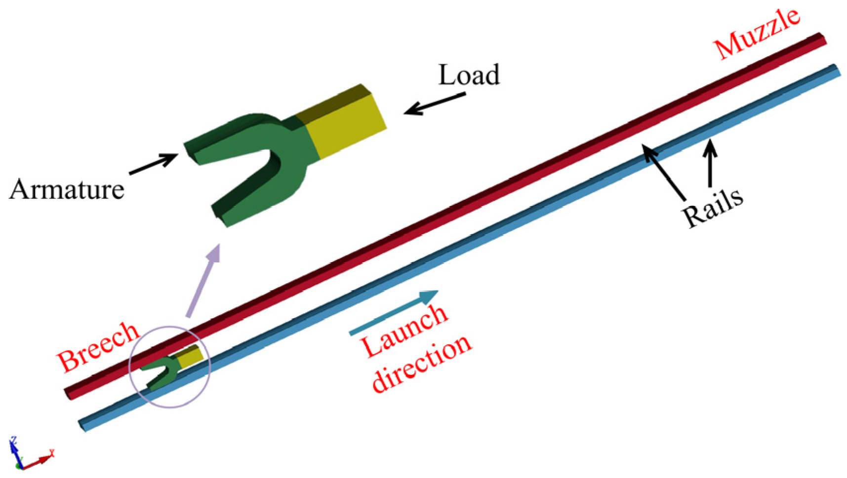
According to the different structures and operating principles, the electromagnetic launcher can be divided into rail launcher, induction coil launcher and reconnection launcher [4,5,6]. The schematic diagram of the electromagnetic rail launcher is shown in Figure 1. It mainly consists of two parallel rails and an armature, which maintains good contact with the rails and can slide in a straight line along the rails [7,8,9]. The driving current flows through the circuit formed by the rails and the armature [10,11]. After the current passes, a strong magnetic field is generated between the two rails, which interacts with the current on the armature to generate an electromagnetic force [12]. The armature is driven when the electromagnetic force is greater than the frictional force. And it is accelerated to hypervelocity [13].
The launcher efficiency is a significant index for evaluating the performance of an electromagnetic rail launcher. Although the operating principle is not complicated, it is not easy to achieve high efficiency. Therefore, it is extremely important to carry out efficiency research on the electromagnetic rail launcher. The current researches mainly focus on the theoretical and simulation calculations of the launcher efficiency and the optimization of the pulsed power supplies [14,15,16,17,18,19], which mainly include the optimization of the structural parameters of the pulsed power supply [20,21], the optimization of the drive current waveform and the optimization of the triggering strategy [22,23]. Geng studied the general laws of armature motion in the bore by theoretical calculations and calculated the main energy transfer process, realizing the optimization of efficiency [24]. Ge investigated the calculation methods and experimental measurement methods of the system efficiency and launcher efficiency of the electromagnetic rail launcher and simulated the relevant efficiency assessment parameters of the rail launcher by simulation software [25]. Wen used finite element software (Ansys) and circuit simulation software (Simulink) to investigate the influence of geometric parameters on the launcher efficiency [26]. Richard developed an EMR model consisting of a rail circuit, PFU circuits and armature dynamics and investigated the laws of influence of variations in the structural parameters on the launcher efficiency [27]. Previous studies have mainly focused on the optimization of the pulsed power supply in electromagnetic rail launchers, as well as theoretical calculations and finite element simulations of the system’s efficiency. Currently, there is a lack of experimental research focused on the study of launcher efficiency, and investigations on the influence of bore parameters on the launcher efficiency through experiments have rarely been reported. The bore parameters of the electromagnetic launcher have an important influence on the inductance gradient L′, current density distribution, contact pressure and linear current density, and the above parameters have a direct influence on the launcher efficiency, so optimizing the bore parameters to enhance the launcher efficiency is of great significance.
In this paper, the combination of finite element simulation and experiment was used to study the influence of bore parameters and load mass on the launcher effective efficiency. Nine sets of comparative experiments were carried out with different bore parameters to investigate the effects on the launcher effective efficiency, and the experiments with different load masses were conducted to study the effects on the effective mass ratio on the launcher effective efficiency. Three repetitive launches were performed for each bore parameter and load mass condition to reduce the random error. The kinetic energy of the armature and the total energy fed into the launcher were used to calculate the launcher effective efficiency, and finite element simulation was also carried out to obtain the motion process of the armature in the bore, the muzzle velocity and the launcher effective efficiency. The launcher effective efficiency calculated by the experiment and simulation were basically the same so that the experiment and the simulation can be mutually confirmed.

2. The Calculation of the Launcher Effective Efficiency

The integrated launch package (ILP) consists of an effective mass and parasitic mass, where armature and polycarbonate guiding rider are the parasitic mass and the load is the effective mass. The effective mass ratio M is defined as the ratio of the effective mass to the ILP mass [5]:
M = m e m m I L P
where mILP is the ILP mass, and mem is the effective mass.
The launcher efficiency [12,13] can be divided into the system efficiency ηs and the launcher efficiency ηL:
η s = E I L P E c
η L = E I L P E i
E i = 0 t u i   d t
where EILP is the kinetic energy of the ILP, Ec is the total energy of pulse power supply, Ei is the input power of the launcher, t is the accelerate processing time of armature in the launcher, i is the driving current of the launcher, and u is the voltage of the breech.
The launcher efficiency is the ratio of the kinetic energy of the ILP to the total energy supplied in the launcher. Since the ILP consists of an effective mass and a parasitic mass, the launcher efficiency ηL can be defined as follows:
η L = 1 2 m p m v 2 E i + 1 2 m em v 2 E i
The ratio of the kinetic energy of the effective mass to the total energy of the launcher is defined as the launcher effective efficiency ηLe:
η L e = 1 2 m em v 2 E i
η L e = 1 2 m I L P v 2 E i 1 2 m p m v 2 E i = η L 1 2 m p m v 2 E i
where mpm is parasitic mass, and v is the muzzle velocity.
The kinetic energy of the ILP comes from the electrical energy stored in the pulsed power supply, and the system efficiency reflects the ability of the system to convert the electrical energy into the kinetic energy of the ILP. When the kinetic energy of the ILP is certain, improving the system efficiency can reduce the input energy, thus reducing the energy demand of the pulsed power supply and improving the mobility of the electromagnetic launch system, which is of great significance for applications. The kinetic energy of the load is an important index reflecting the destructive capability, and the launcher effective efficiency is an important index characterizing the conversion of electromagnetic energy into kinetic energy of the load, so this paper takes the launcher effective efficiency as the main reference index.

3. Experiment Setup

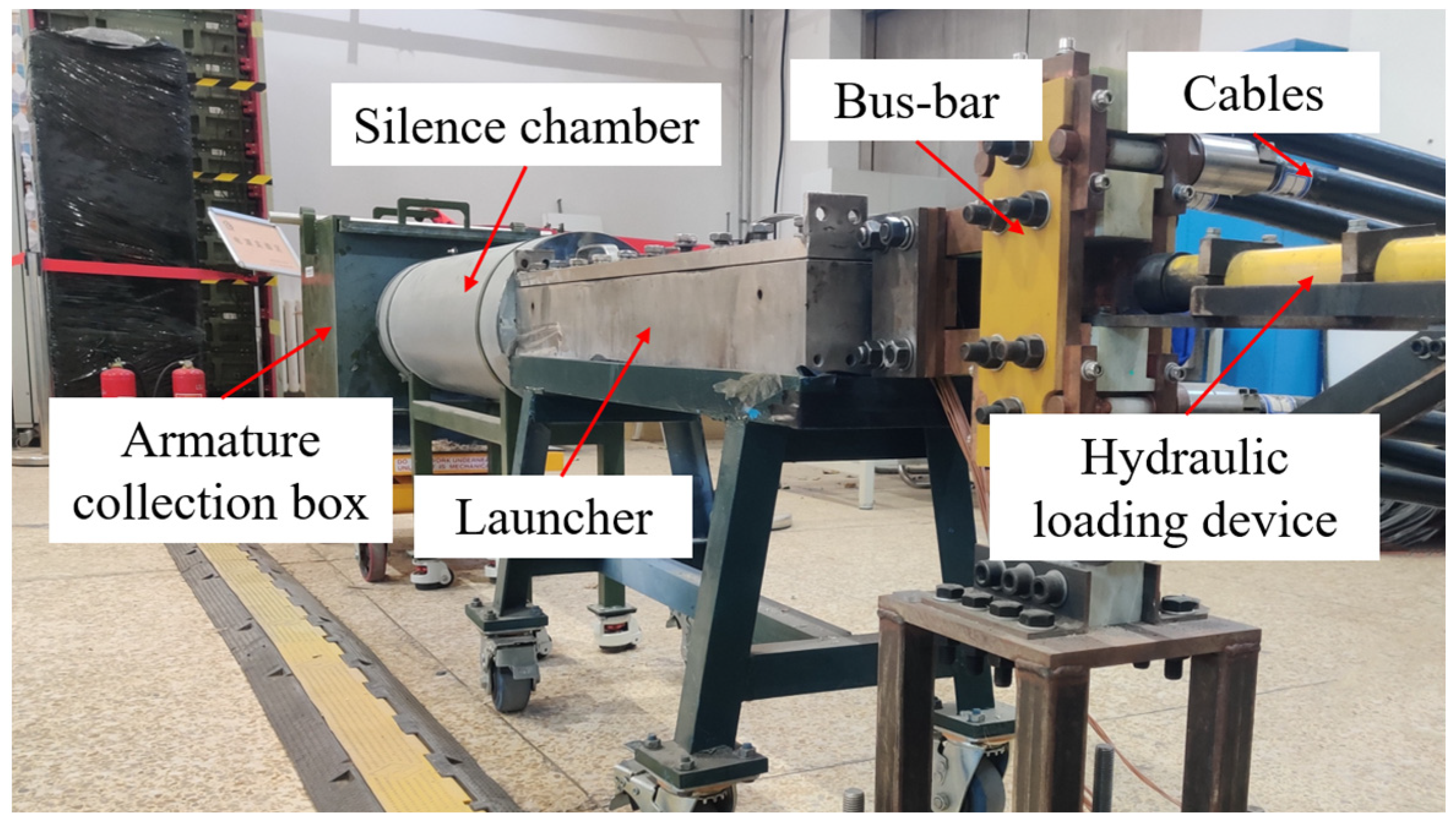
Nine sets of experiments were carried out. Each set included three shots, and the aluminum deposited on the rail was cleaned after each experiment to ensure that the initial experimental conditions were the same. The experimental equipment mainly consists of a 270 kJ pulsed power supply, a 12 mm small diameter launcher and a pulsed power control system. The driving current, the voltage of muzzle and breech and the velocity of the ILP were measured by the Rogowski Coil with an accuracy of 0.02 mV/A, the high-voltage differential probe with an accuracy of 0.01 V and the B-dot with an accuracy of 0.02 μs. The experimental platform includes a hydraulic loading device, a bus-bar, cables, a small-caliber launcher, a silence chamber and an armature collection box, as shown in Figure 2. The armature is pushed to a specified position in the bore by the hydraulic loading device, and the electrical energy is gathered by the bus bar and fed into the rail, and the armature is collected by the armature collection box.
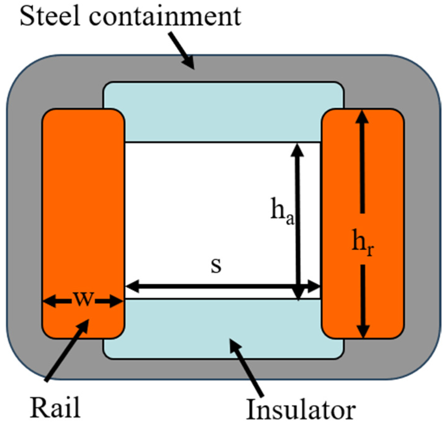
Figure 3 depicts the shape and specific parameters of the launcher’s bore cross-section. The launcher has two rails on the left and right sides, as well as two insulators at the top and bottom. The rails and insulators are encased in additional insulating materials and stainless steel shells on the exterior, ensuring the overall safety of the equipment. The main parameters of the bore are the rail height (hr), rail and armature contact height (ha), rail thickness (w) and rail separation (s).
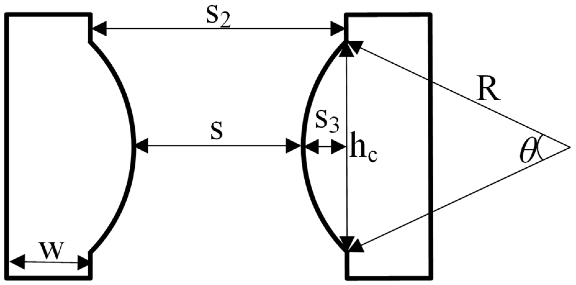
The analyzed rail shapes comprise a plane rail (with a convex arc height of 0 mm) and a convex arc rail (with a convex arc height of 0.5 mm and 1 mm, respectively), as shown in Figure 4. When the rail is plane, the rail separation (s) refers to the distance between the two rails; when the rail is convex, the rail separation (s) is generally defined as the distance between the peaks of the convex arcs. The convex rail parameters include the convex arc height (s3), chord length (hc), arc radius (R) and central angle (θ). The chord length (hc) and the rail armature contact height (ha) in the plane rail are equivalent and do not vary. The armature chord length (hc) is consistently 12 mm. The convex arc on the rail with a height of 0.5 mm has an arc radius of 36.25 mm and a central angle of 19.05 degrees. Similarly, the convex arc on the rail with a height of 1 mm has an arc radius of 18 mm and a central angle of 37.85 degrees.
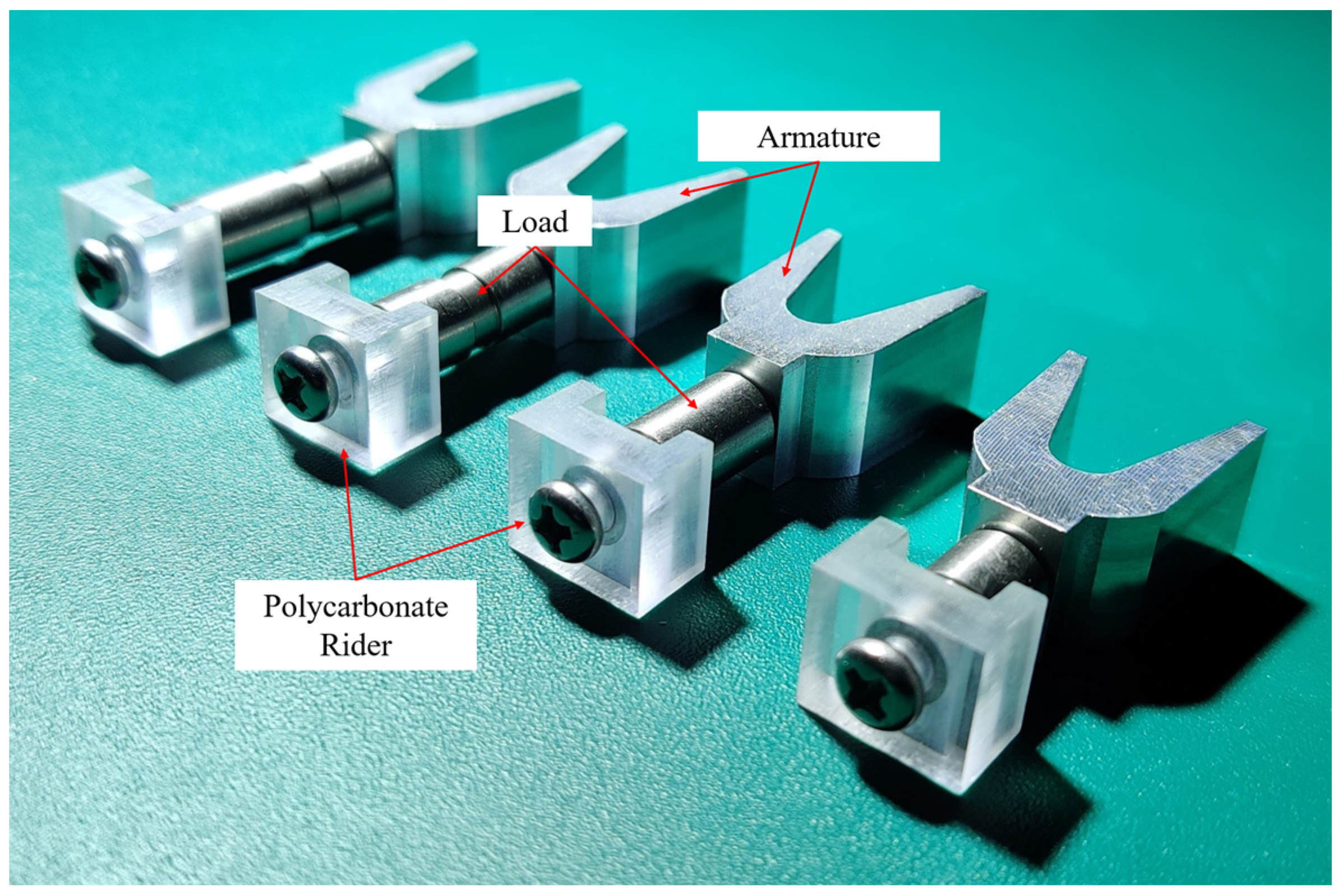
The ILP mainly consists of an aluminum alloy armature, stainless steel mass and polycarbonate rider. The physical diagram of the armature carrying different loads is given in Figure 5. The experimental parameters include the convex arc height (s3), rail separation (s) and load mass. Variations in rail separation and convex arc height have a minor influence on the armature’s mass and may be disregarded; the armature’s mass was determined to be 8.41 g by measurements. There were two different specifications for the loads, which were 3.15 g and 6.61 g. The change in the effective mass ratio (0, 0.28, 0.43, 0.49, 0.56) and the change in the overall mass of the ILP (8.41 g~18.71 g) are achieved by different combinations of loads.
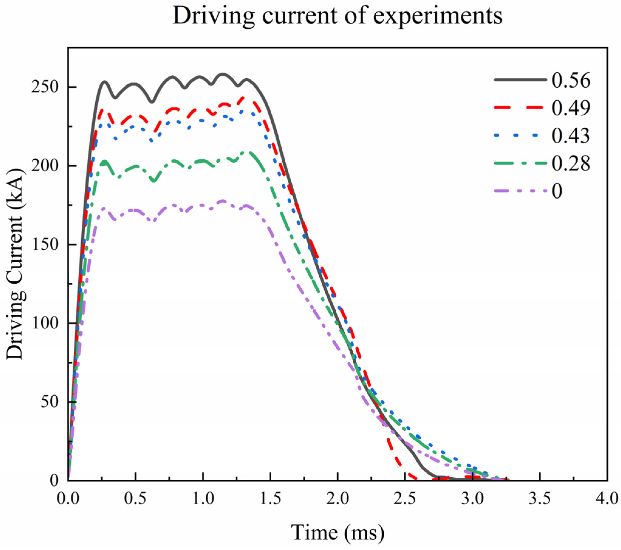
Figure 6 demonstrates the typical driving current waveforms at different effective mass ratios. The change in the effective mass ratio is accomplished by varying the mass of the load on the armature, and under the same bore parameters conditions, the armature mass remains constant. The change in the load mass will not only change the effective mass ratio of the ILP but also lead to a change in the total mass of the ILP. Due to the different total masses of the ILP (8.4 g~18.7 g), the amplitudes of driving current waveforms are calculated to be 175 to 250 kA in order to ensure that the ILPs have the same acceleration process in the bore and the same muzzle velocity, on the consideration of electromagnetic force, contact pressure and friction.

4. Results and Discussion of Experiments

4.1. Effect of Effective Mass Ratio on Launcher Effective Efficiency

In the experiment, the influence of the effective mass ratio on the launcher effective efficiency was investigated under the same launch conditions, and the results are shown in Table 1. From the experimental results, it can be observed that the launcher effective efficiency increased with the increase in the effective mass ratio within the range of 0.28 to 0.56, and as the effective mass ratio gradually increased from 0.28 to 0.56, the launcher effective efficiency increased significantly from 7.97% to 17.17%, and the launcher effective efficiency also increased from 7.46% to 8.89% with the increase in the effective mass ratio under conditions of different bore parameters. The average increment was 8.24%.
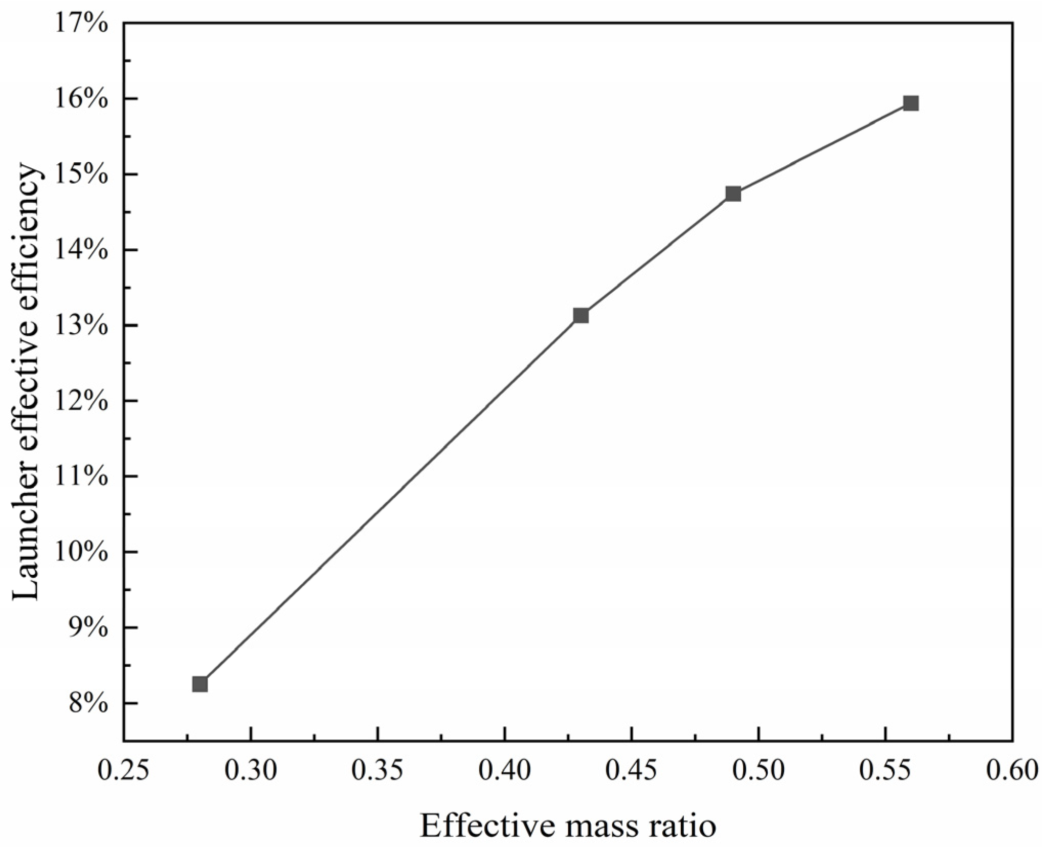
Figure 7 shows the variation between the average launcher effective efficiency and the effective mass ratio in the experiments. During the process of increasing the effective mass ratio from 0.28 to 0.56, the slope of the curve in the figure revealed a declining tendency, which indicated that the increase in the effective mass ratio had a limited effect on the launcher effective efficiency. In addition, when the effective mass ratio was 0.28, the launcher effective efficiency varied between 7.91% and 8.58% for different bore parameters, with a maximum deviation of 0.67%. When the effective mass ratio was increased to 0.49 and 0.56, the difference in the launcher effective efficiency under various conditions was 2.27% and 1.60%, respectively. The relative error of the armature muzzle velocity improved when the effective mass ratio was increased, suggesting a negative impact on the armature muzzle velocity as a result of increasing the effective mass ratio. Therefore, it is important to comprehensively consider both the armature and load to ensure good launch performance.
Equations (5)–(7) revealed that the launcher efficiency included two parts: the launcher effective efficiency with the effective mass and the launcher ineffective efficiency with a negative mass. When the bore parameters of the launcher remained constant, the energy conversion efficiency ηL was basically unchanged. By increasing the effective mass while keeping the armature mass constant, the mass of the ILP rose. The feed current was increased to ensure that the ILP had the same motion process in the bore and the same muzzle velocity. At this point, the kinetic energy of the negative mass remained constant while the total input energy increased, resulting in a decrease in the efficiency of the negative mass and an improvement in the launcher effective efficiency ηLe.
The experimental results indicate that an increase in the effective mass ratio can improve the launcher effective efficiency, enabling more electrical energy to be converted into the kinetic energy of the load by the launcher, improving the efficiency of electrical energy utilization. However, it will also affect the consistency of the muzzle velocity to some extent. Consequently, it is necessary to fully consider the quality match between the armature and load to ensure high effective efficiency and good consistency of muzzle velocity.

4.2. Effect of Rail Separation on Launcher Effective Efficiency

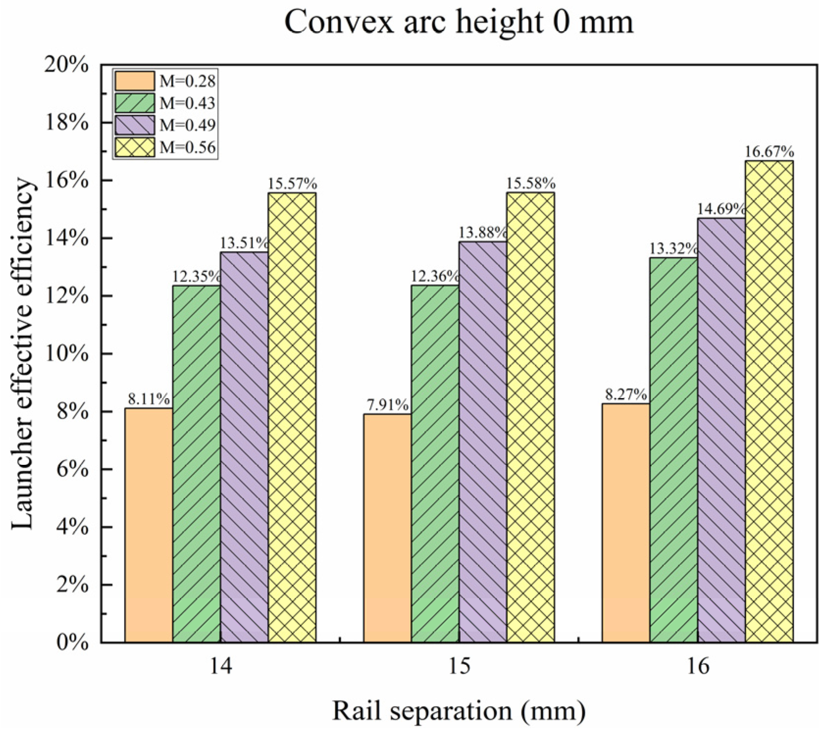
Figure 8 shows the influence of rail separation and effective mass ratio on the launcher effective efficiency when the rail is plane. As shown in the figure, the launcher effective efficiency had a consistent improvement with the increment in rail separation, increasing from 8.11% to 8.27% at an effective mass ratio (M) of 0.28, from 12.35% to 13.32% at M = 0.43, from 13.51% to 14.69% at M = 0.49 and from 15.57% to 16.67% at M = 0.56. Furthermore, as the rail separation was increased from 14 mm to 16 mm, the launcher effective efficiency increased by an average of 0.85%. When the rail separation was constant, the launcher effective efficiency improved with the increase in the effective mass ratio, and the launcher effective efficiency increased by an average of 7.84% while the effective mass ratio increased from 0.28 to 0.56.
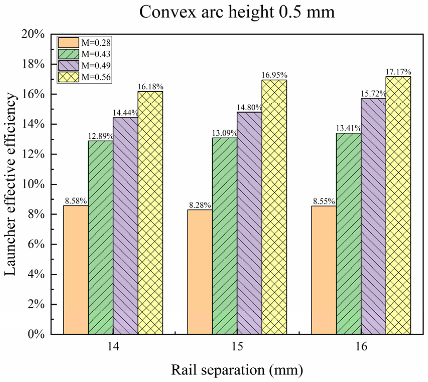
Figure 9 displays the change in launcher effective efficiency at a convex arc height of 0.5 mm, following the same trend observed in Figure 8. In the process of increasing the rail separation from 14 mm to 16 mm, the launcher effective efficiency increased by an average of 0.69%. When the rail separation was constant, the launcher effective efficiency rose by an average of 8.30% while the effective mass ratio increased from 0.28 to 0.56.
Figure 10 demonstrates the change in launcher effective efficiency at a convex arc height of 1 mm, similar to Figure 8. In the process of raising the rail separation from 14 mm to 16 mm, the launcher effective efficiency increased by an average of 0.74%. When the rail separation was constant, the launcher effective efficiency rose by an average of 8.67% while the effective mass ratio rose from 0.28 to 0.56.
Figure 8, Figure 9 and Figure 10 indicate that when the convex arc height and the effective mass ratio remained constant, the launcher effective efficiency increased with increasing rail separation. Under different effective mass ratios, the launcher effective efficiency increased by an average of 0.70% with the raising of rail separation from 14 mm to 16 mm. This observation was related to the fact that increasing the rail separation improved the inductance gradient L′ of the launcher, and the growth in armature mass was relatively small. It was important to notice that the overall mass and effective mass ratio of the ILP remained substantially unaltered. Consequently, the rise in the inductance gradient L′ had a larger impact on the launcher effective efficiency than the increment in armature mass. Therefore, increasing the rail separation was identified as a component that positively affected the launcher effective efficiency.

4.3. Effect of Convex Arc Height on Launcher Effective Efficiency

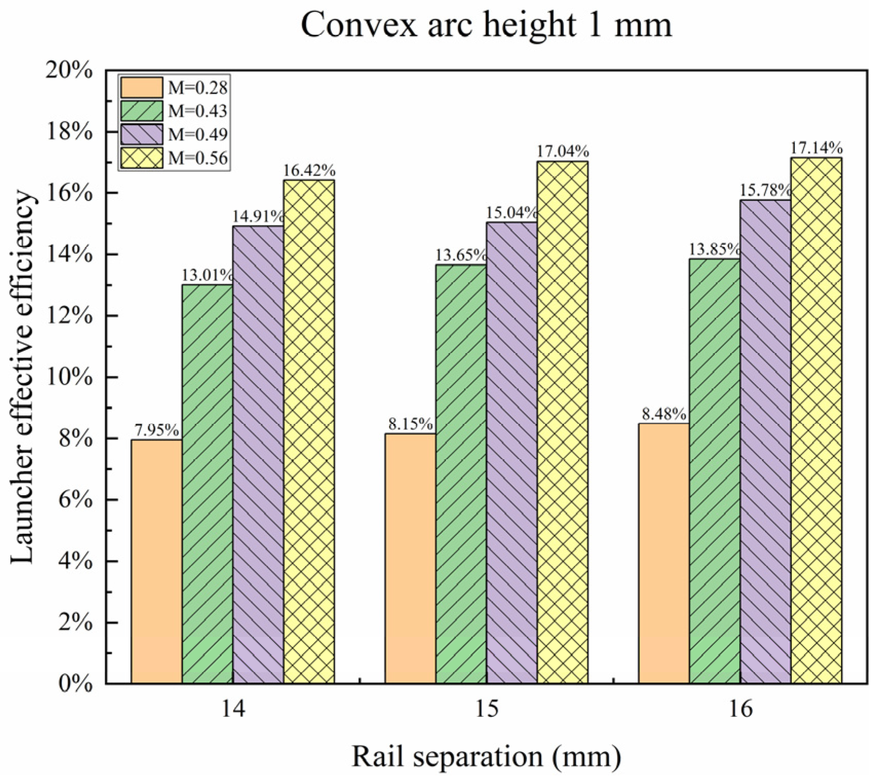
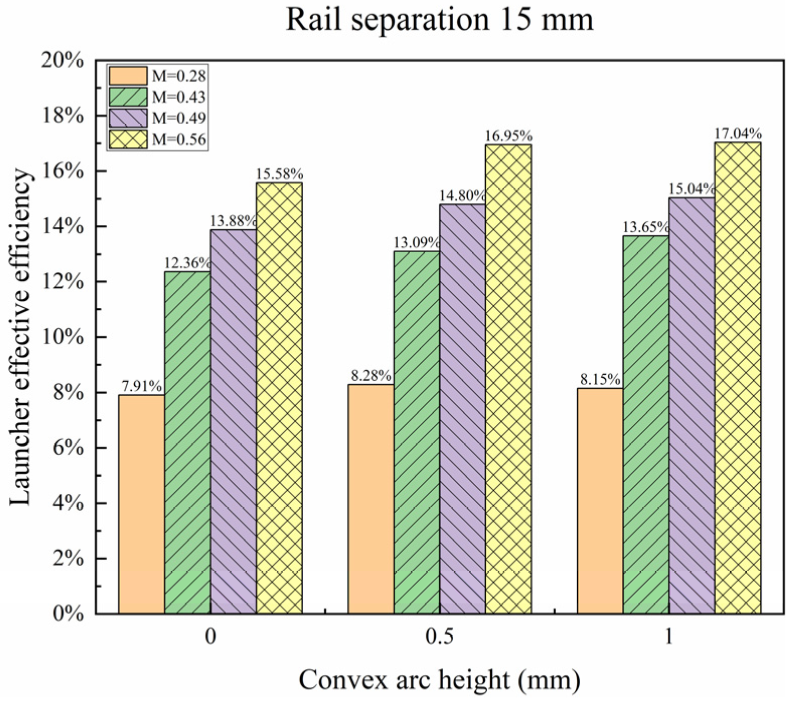
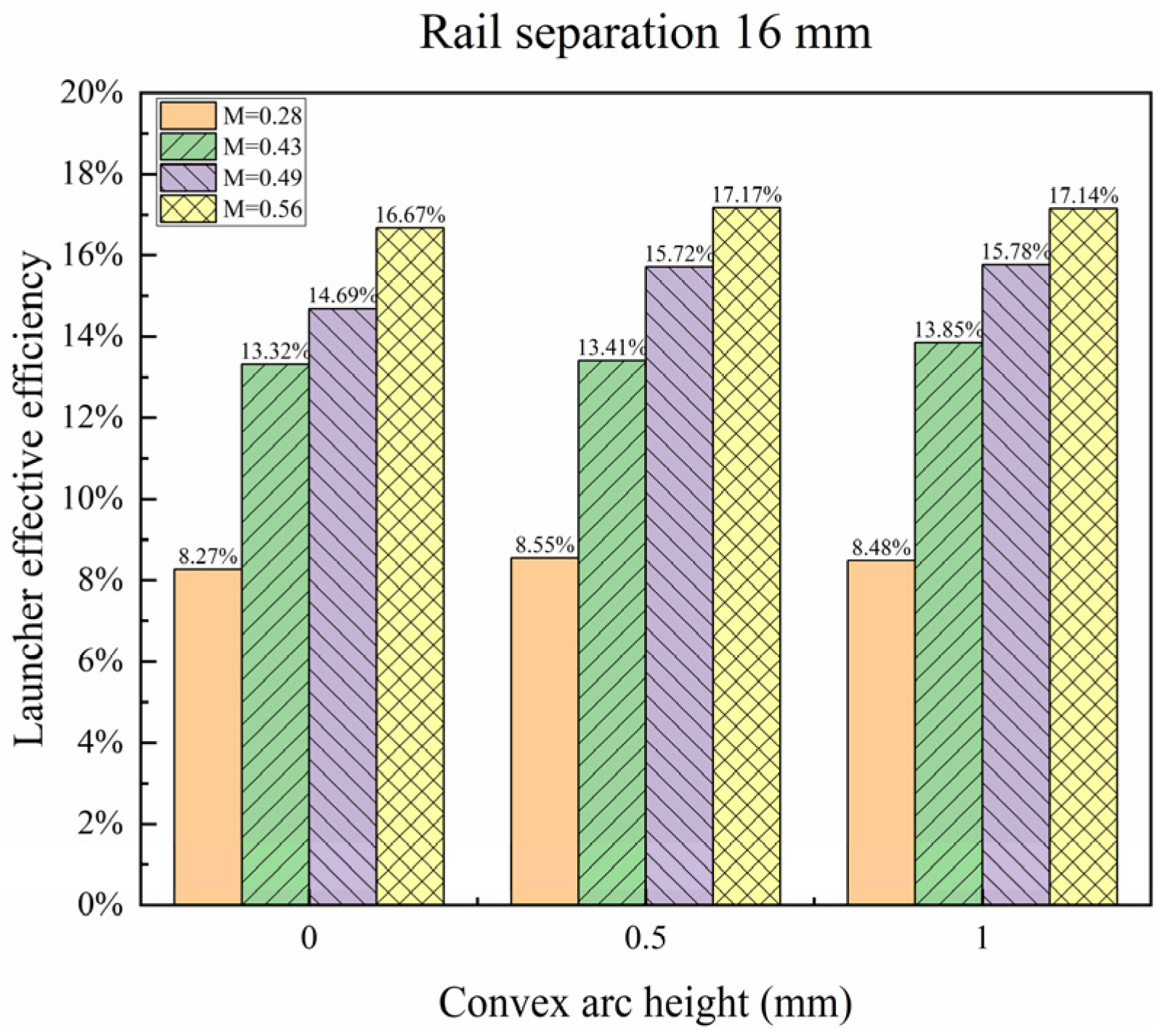
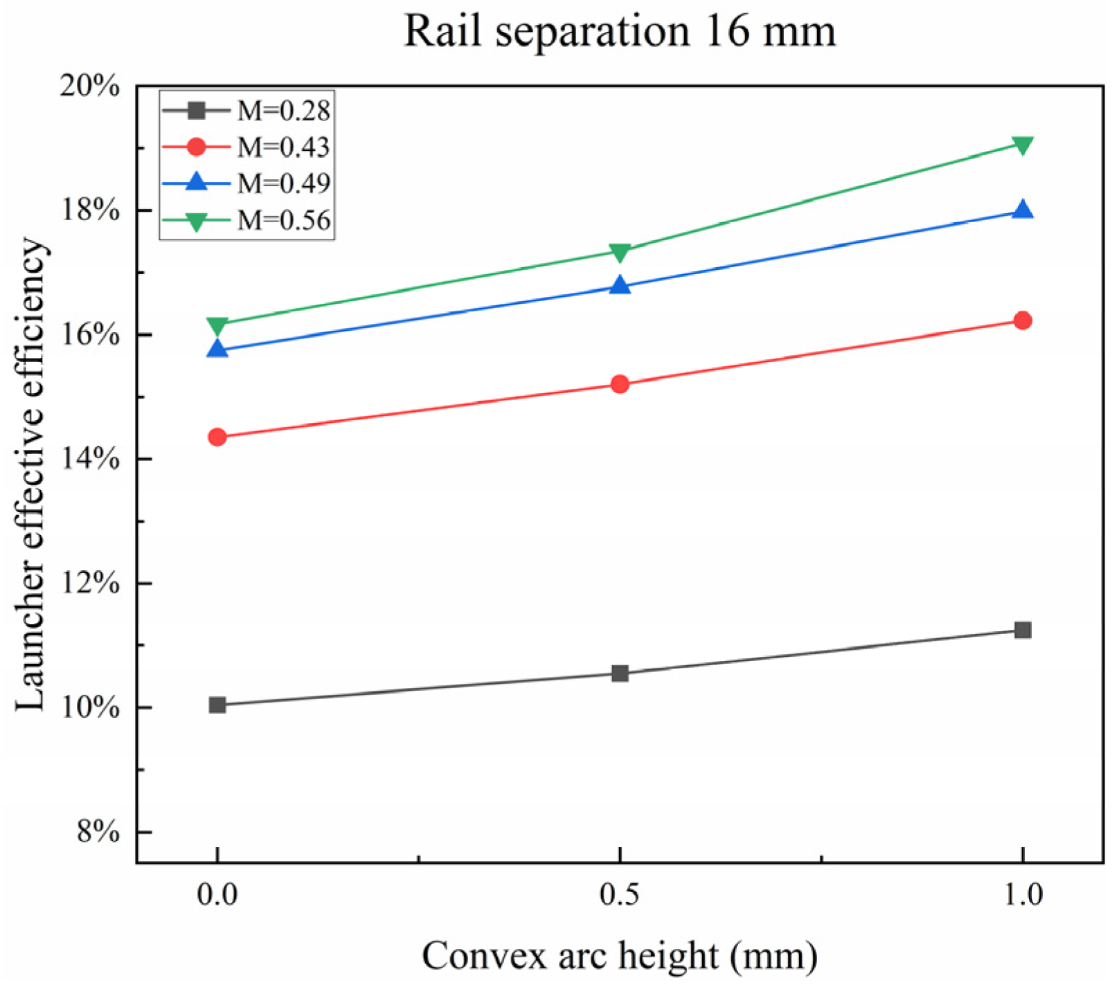
Figure 11, Figure 12 and Figure 13 show the relationship between the launcher effective efficiency and the convex arc height. The launcher effective efficiency increased with the increase in convex arc height. Under varied effective mass ratios, a rise in convex arc height resulted in an approximately 0.77% enhancement of the launcher effective efficiency. The structure of the convex arc rail is represented in Figure 4, and its rail separation (s) is defined as the distance between the peaks of the convex arcs. If the convex arc rail is separated into rectangular and arc-shaped parts, the inductance gradient L′ generated by the arc-shaped segment remains constant during the change in the convex arc height. Nevertheless, an increase in the convex arc height will lead to a growth in s2 and a decrease in w, which is equivalent to an increase in the rail separation and a drop in the thickness of the rectangular segment of the rail, thereby increasing the inductance gradient L′ of the entire convex arc rail and improving the launcher effective efficiency.
From the above experiment, it can be concluded that within a specific range of the effective mass ratio, an increment in the effective mass ratio also resulted in an enhancement in the launcher effective efficiency. A comparison of the influence of different bore parameters on the launcher effective efficiency revealed that an increase in rail separation and convex arc height is also beneficial for improving the launcher effective efficiency. Therefore, the findings suggest that during the design process of the electromagnetic rail launcher, an appropriate increment in the convex arc height and rail separation, as well as a growth in the effective mass ratio, will help to improve the system efficiency and launcher effective efficiency.

5. Simulation Theory and Modeling

The simulation calculations include electromagnetic fields, temperature fields and structural fields. The electromagnetic fields couple with the structural fields through the electromagnetic force and the displacement of the armature. The electromagnetic fields couple with the temperature fields through the variable conductivity resulting from the Joule heat. The temperature fields couple with structural fields through the frictional heat produced by the action of the armature, as well as thermal stress resulting from the change in temperature [28,29].
The heat transfer between the rails and armature, the contact resistance, the conductivity, the thermal conductivity and the specific heat capacity that will vary with temperature were considered in the simulation [30,31].
As the launching process is magnetic quasi-static, using the magnetic vector A and the electric scalar potential φ as unknown quantities, the Maxwell equations are expressed in the following equations [32]:
× 1 μ × A + σ A t + φ = 0
σ A t σ φ = 0
where σ is the electrical conductivity, μ is the permeability of the conductors, A is the magnetic vector potential, φ is the electrical scalar potential and t is time.
The thermal diffusion equation is deduced under the assumption of energy balance [33]:
ρ c T t κ Δ T = Q
Q = J J σ
σ A t + φ = J
where κ, T, ρ, c and J are the thermal conductivity, temperature, solid density, specific heat and current density, and Q is the heat generated in the conductor due to Joule heating.
We consider the elastic deformation of the armature and rails to facilitate the coupling calculations, the governing equations can be expressed as follows [32]:
s i j , j + f i = ρ u i
F = J × B
B = × A
where s, f and u are the stress tensor, force per unit volume and structural displacement, F is the electromagnetic driving force, and B is the magnetic flux density.
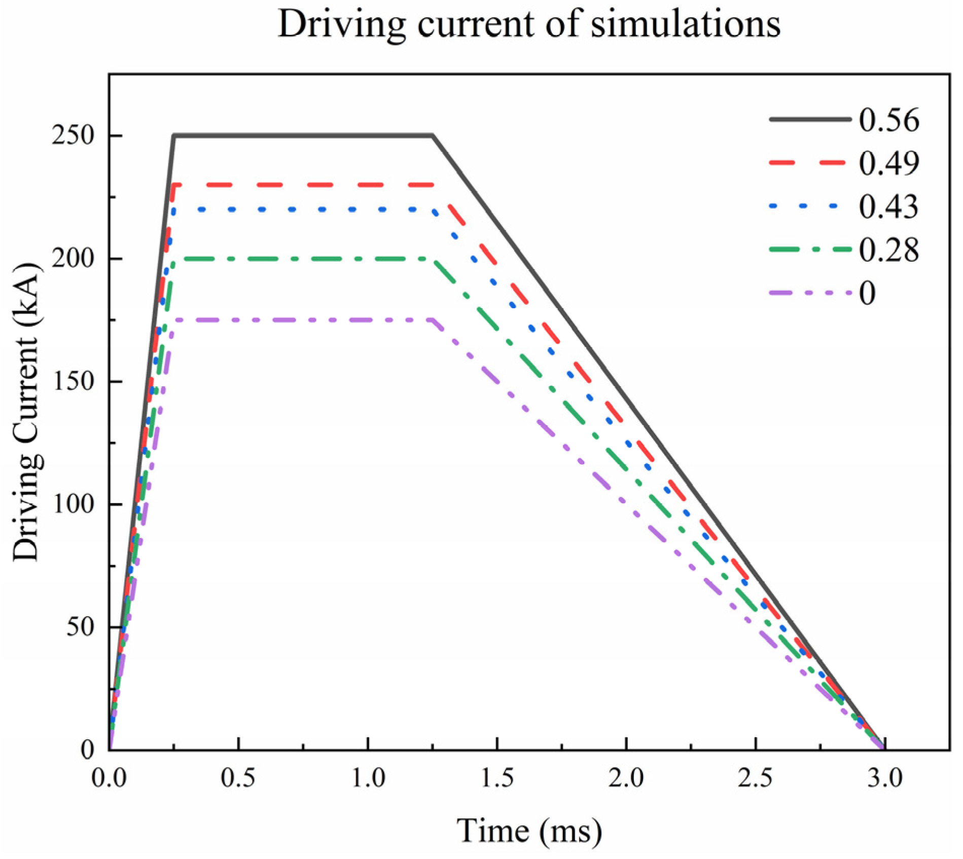
The finite element method was used in the simulation, with all nodes on the back of the two rails completely fixed and the armature fixed in the z-direction. The simulation model and parameters are shown in Figure 14 and Table 2. In order to ensure that the armature has the same acceleration process in the bore and muzzle velocity, the driving current waveform of the simulation is calculated, as shown in Figure 15.

6. Results and Discussion of Simulation

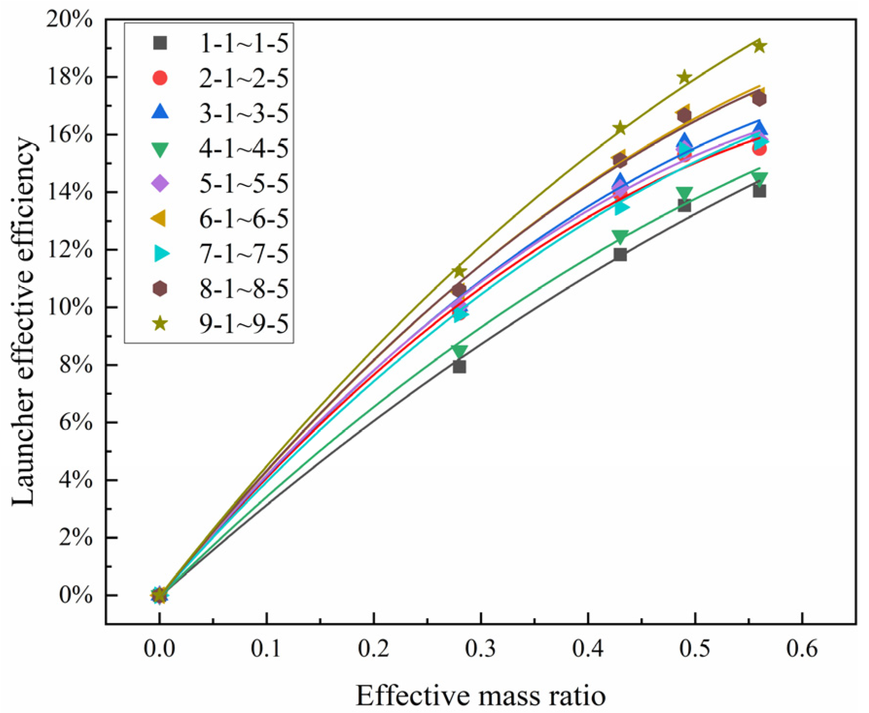
The simulation results are shown in Figure 16 and Table 3, and the corresponding change curves are obtained by fitting the discrete data points. The results indicate that the launcher effective efficiency increased with the increase in the effective mass ratio, while the rail separation and convex arc height remained constant. But as the effective mass ratio rose, the slope of the curve gradually decreased, suggesting that when the rail separation and convex arc height remained unchanged, the launcher effective efficiency would approach a certain limit value as the effective mass ratio continued to rise.
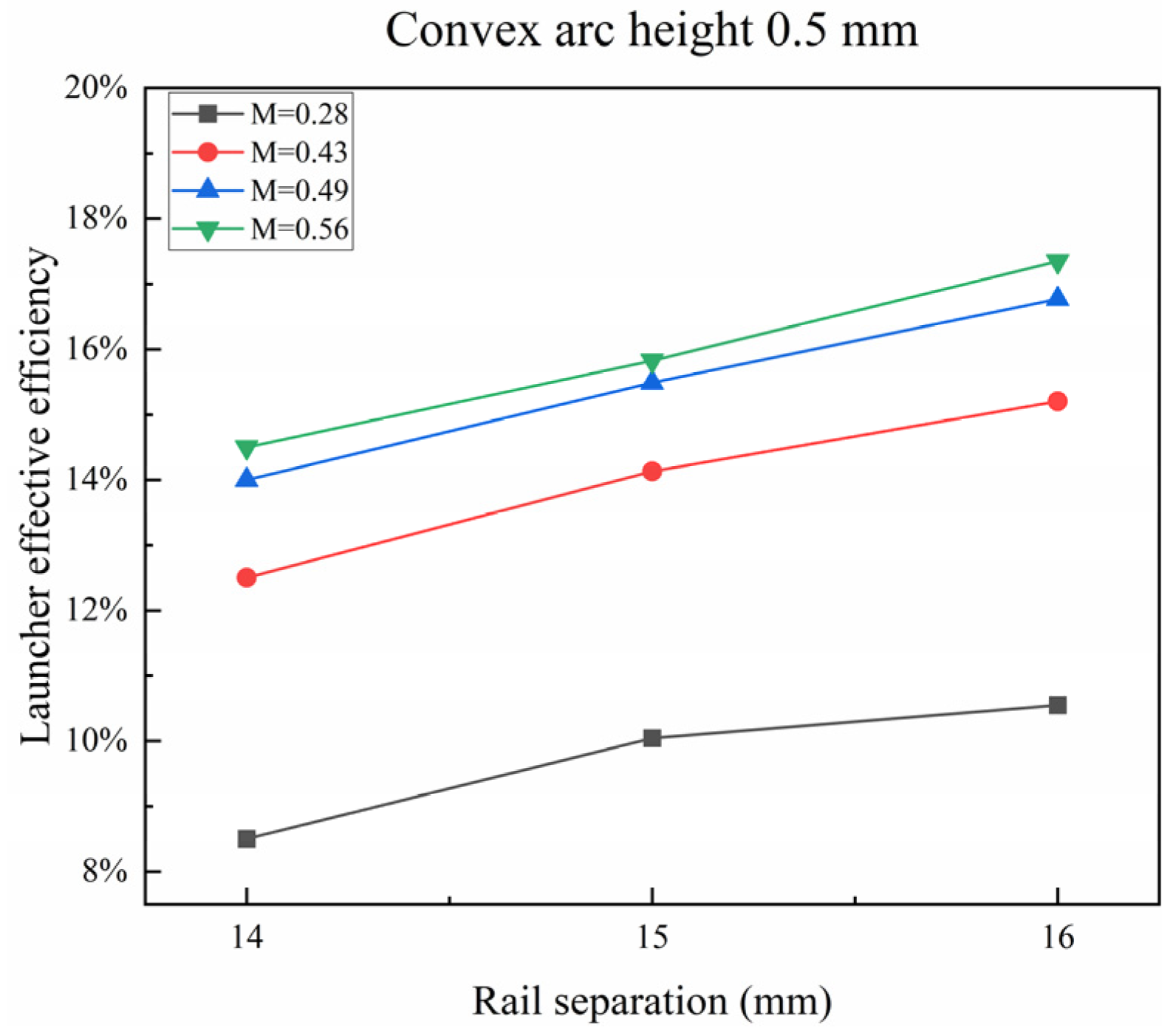
Figure 17, Figure 18 and Figure 19 show the relationship between the launcher effective efficiency and trail separation when the convex arc heights are 0 mm, 0.5 mm and 1 mm, respectively. The launcher effective efficiency improved with the growth of rail separation. Under varied effective mass ratios, when the rail separation increased from 14 mm to 16 mm, the launcher effective efficiency rose by an average of 2.45%. According to the driving force formula of the electromagnetic launcher, it can be stated that the inductance gradient L′ improved with the increase in rail separation. When the driving current is constant, increasing L′ will increase the electromagnetic driving force, increase the kinetic energy, and thus improve the launcher effective efficiency. In addition, the variation in launcher effective efficiency was smaller for most of the curves when it was increased from 14 mm to 15 mm compared to when it was increased from 15 mm to 16 mm. This indicates that the rail separation had a limited influence on the launcher effective efficiency. When the ratio of rail separation to height reaches a certain level, increasing the rail separation will not significantly increase the launcher effective efficiency.
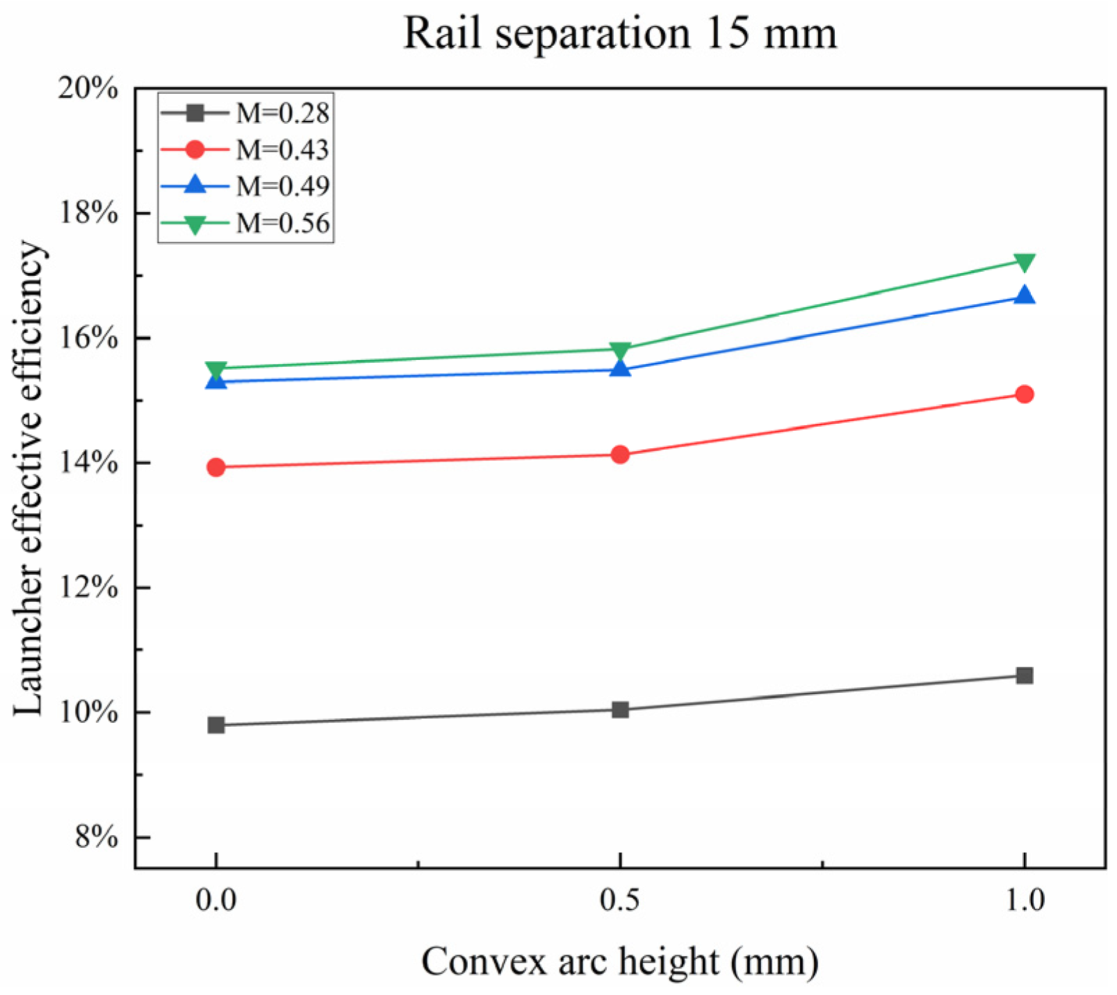
Figure 20, Figure 21 and Figure 22 show the relationship between the launcher effective efficiency and convex arc height when the rail separation is 14 mm, 15 mm and 16 mm, respectively. The launcher effective efficiency improved with the increase in convex arc height. Under the conditions of different effective mass ratios, the average launcher effective efficiency rose by 1.70% when the convex arc height increased from 0 mm to 1 mm.
The above simulation results indicate that when the effective mass ratio was within the range of 0.28~0.56, the launcher effective efficiency increased with the increase in the effective mass ratio, but the rate of change gradually decreased. When the convex arc height remained constant, the launcher effective efficiency improved with the increase in the rail separation; when the rail separation remained constant, the launcher effective efficiency increased with the increase in convex arc height. The simulation results were remarkably consistent with the experimental results, and the experiment fully verifies the correctness of the simulation results.

7. Conclusions

In this study, a combination of finite element simulations and experiments were used to study the influence of bore parameters and effective mass ratio in the launcher effective efficiency of electromagnetic rail launchers, respectively, and the results show that:
  • The launcher effective efficiency increases with the growth of the effective mass ratio, and the launcher effective efficiency improves from 7.91% to 17.17% when the effective mass ratio rises from 0.28 to 0.56. The average increment of the launcher effective efficiency is 8.24% under different cross-section geometrical parameters.
  • The launcher efficiency increases with the increment in the rail separation; the launcher effective efficiency rises by 0.70% on average when the rail separation increases from 14 mm to 16 mm, and the increase in the launcher effective efficiency decreases with the increment in rail separation;
  • The launcher effective efficiency increases with the increment in the convex arc height; when the convex arc height increases from 0 mm to 1 mm, the launcher effective efficiency rises by 0.77% on average.
This investigation comprehensively examined the influence of the bore parameters and effective mass ratio on launcher effective efficiency of small-caliber electromagnetic launchers. The experimental results were highly consistent with the simulation results, which verified the correctness of the simulation model. The results may help to select bore parameters with high launcher effective efficiency and to a certain extent, guide the optimal design of large-caliber launchers and promote the application of electromagnetic launchers.

Author Contributions

Conceptualization and validation, N.X. and W.T.; resources, J.L.; writing—review and editing, P.Y.; supervision, P.Y. All authors have read and agreed to the published version of the manuscript.

Funding

This research received no external funding.

Data Availability Statement

The original contributions presented in the study are included in the article, further inquiries can be directed to the corresponding author.

Conflicts of Interest

The authors declare no conflicts of interest. The funders had no role in the design of the study; in the collection, analyses, or interpretation of data; in the writing of the manuscript, or in the decision to publish the results.

References

  1. Li, J.; Yan, P.; Yuan, W. Electromagnetic Gun Technology and Its Development. High Volt. Eng. 2014, 40, 1052–1064. [Google Scholar]
  2. Marshall, R.A.; Wang, Y. Railguns: Their Science and Technology; China Machine Press: Beijing, China, 2004. [Google Scholar]
  3. Fair, H.D. Guest Editorial The Past, Present, and Future of Electromagnetic Launch Technology and the IEEE International EML Symposia. IEEE Trans. Plasma Sci. 2013, 41, 1024–1027. [Google Scholar] [CrossRef]
  4. Wang, Y.; Marshall, R.A.; Cheng, S. Physics of Electric Launch; Science Press: Beijing, China, 2004; pp. 1–47. [Google Scholar]
  5. Ellis, R.L.; Poynor, J.C.; McGlasson, B.T.; Smith, A.N. Influence of bore and rail geometry on an electromagnetic naval railgun system. IEEE Trans. Magn. 2005, 41, 182–187. [Google Scholar] [CrossRef]
  6. Marshall, R.A. Railgun bore geometry, round or square? IEEE Trans. Magn. 1999, 35, 427–431. [Google Scholar] [CrossRef]
  7. McFarland, J.; McNab, I.R. A long-range naval railgun. IEEE Trans. Magn. 2003, 39, 289–294. [Google Scholar] [CrossRef]
  8. Zhu, R.; Zhang, Q.; Li, Z.; Jin, L.; Wang, R. Impact physics model and influencing factors of gouging for electromagnetic rail launcher. In Proceedings of the 2014 17th International Symposium on Electromagnetic Launch Technology, La Jolla, CA, USA, 7–11 July 2014; pp. 1–6. [Google Scholar]
  9. Hsieh, K.T.; Kim, B.K. International railgun modelling effort. IEEE Trans. Magn. 1997, 33, 245–248. [Google Scholar] [CrossRef]
  10. Meger, R.A.; Cooper, K.; Jones, H.; Neri, J.; Qadri, S.; Singer, I.L.; Sprague, J.; Wahl, K.J. Analysis of rail surfaces from a multishot railgun. IEEE Trans. Magn. 2005, 41, 211–213. [Google Scholar] [CrossRef]
  11. Bauer, D.P. Achieving high efficiency with conventional railgun launchers. IEEE Trans. Magn. 1995, 31, 263–266. [Google Scholar] [CrossRef]
  12. Khatibzadeh, A.; Besmi, M.R. Improve dimension of projectile for increasing efficiency of electromagnetic launcher. In Proceedings of the 4th Annual International Power Electronics, Drive Systems and Technologies Conference, Tehran, Iran, 13–14 February 2013; pp. 55–59. [Google Scholar]
  13. Fat, O.V.; Usuba, S.; Yoshida, M.; Kakudate, Y.; Yokoi, H.; Fujiwara, S. Electromagnetic processes and launch efficiency of railgun systems. IEEE Trans. Magn. 1997, 33, 532–537. [Google Scholar]
  14. Li, Z.X.; Hao, S.P.; Ma, F.Q.; Li, B.M. Current Situation and Development of Pulsed Power Supply Module Technology for Electric Gun. Acta Armamentarii 2020, 41, 1–7. [Google Scholar]
  15. Liu, X.; Yu, X.; Li, Z. Inductance calculation and energy density optimization of the tightly coupled inductors used in inductive pulsed power supplies. IEEE Trans. Plasma Sci. 2017, 45, 1026–1031. [Google Scholar] [CrossRef]
  16. Sung, V.; Odendaal, W.G. The Effect of Changing Launch Package Mass on the Electromechanical Conversion Efficiency of Railguns. IEEE Trans. Plasma Sci. 2019, 47, 2521–2531. [Google Scholar] [CrossRef]
  17. Zhang, P.; Gao, W.; Niu, Q.; Dong, S. Numerical Analysis of Aerodynamic Thermal Properties of Hypersonic Blunt-Nosed Body with Angles of Fire. Energies 2023, 16, 1740. [Google Scholar] [CrossRef]
  18. Ceylan, D.; Keysan, O. Effect of conducting containment on electromagnetic launcher efficiency. In Proceedings of the 2017 18th International Symposium on Electromagnetic Fields in Mechatronics, Electrical and Electronic Engineering (ISEF) Book of Abstracts, Lodz, Poland, 14–16 September 2017; pp. 1–2. [Google Scholar]
  19. Liu, S.; Miao, H.; Liu, M. Investigation of the Armature Contact Efficiency in a Railgun. IEEE Trans. Plasma Sci. 2019, 47, 3315–3319. [Google Scholar] [CrossRef]
  20. Cao, G.; Xiang, H.; Qiao, Z.; Liang, C.; Yuan, X.; Wang, J.; Lei, B. Utilization Optimization of Capacitive Pulsed Power Supply in Railgun. Energies 2022, 15, 5051. [Google Scholar] [CrossRef]
  21. Liu, X.; Yu, X.; Liu, X. Influences of electric parameters of pulsed power supply on electromagnetic railgun system. IEEE Trans. Plasma Sci. 2016, 43, 3260–3267. [Google Scholar]
  22. Chang, X.; Yu, X.; Liu, X.; Li, Z. Armature Velocity Control Strategy and System Efficiency Optimization of Railguns. IEEE Trans. Plasma Sci. 2018, 46, 3634–3639. [Google Scholar] [CrossRef]
  23. Gong, C.; Yu, X.; Liu, X. Study on the system efficiency of the synchronously-triggered capacitive pulsed-power supply in the electromagnetic railgun system. In Proceedings of the 2014 17th International Symposium on Electromagnetic Launch Technology, La Jolla, CA, USA, 7–11 July 2014; pp. 1–6. [Google Scholar]
  24. Geng, Y.; Xu, L. Analysis of Projectile Motion in Bore and Transfer Efficiency for Electromagnetic Railgun. In Proceedings of the 2010 WASE International Conference on Information Engineering, Beidai, China, 14–15 August 2010; Volume 3, pp. 156–160. [Google Scholar]
  25. Ge, X.; Cao, B.; Li, J.; Sun, X.; Yang, Y.L. Research on evaluation of electromagnetic railgun efficiency. In Proceedings of the 2014 17th International Symposium on Electromagnetic Launch Technology, La Jolla, CA, USA, 7–11 July 2014; pp. 1–5. [Google Scholar]
  26. Wen, Y.; Dai, L.; Lin, F. Effect of Geometric Parameters on Equivalent Load and Efficiency in Rectangular Bore Railgun. IEEE Trans. Plasma Sci. 2021, 49, 1428–1433. [Google Scholar] [CrossRef]
  27. Meyer, R.T.; DeCarlo, R.A.; Dickerson, J. Energy Transfer Efficiency Optimization in an Electromagnetic Railgun. IEEE Trans. Plasma Sci. 2017, 45, 702–710. [Google Scholar] [CrossRef]
  28. Yuan, J.; Geng, Y.; Shen, Z.; Li, J. Approach for Simulating Air Gap Between Armature and Rails Based on the Finite-Element Method. IEEE Trans. Plasma Sci. 2017, 45, 1591–1595. [Google Scholar] [CrossRef]
  29. Bayati, M.S.; Keshtkar, A. Study of the Current Distribution, Magnetic Field, and Inductance Gradient of Rectangular and Circular Railguns. IEEE Trans. Plasma Sci. 2013, 41, 1376–1381. [Google Scholar] [CrossRef]
  30. Powell, J.D.; Zielinski, A.E. Current and heat transport in the solid-armature railgun. IEEE Trans. Magn. 1995, 31, 645–650. [Google Scholar] [CrossRef]
  31. Powell, J.D.; Zielinski, A.E. Observation and simulation of solid-armature railgun performance. IEEE Trans. Magn. 1999, 35, 84–89. [Google Scholar] [CrossRef]
  32. Lin, Q.-H.; Li, B.-M. Numerical simulation of interior ballistic process of railgun based on the multi-field coupled model. Def. Technol. 2016, 12, 101–105. [Google Scholar] [CrossRef]
  33. Hsieh, K. A Lagrangian formulation for mechanically, thermally coupled electromagnetic diffusive processes with moving conductors. IEEE Trans. Magn. 1995, 31, 604–609. [Google Scholar] [CrossRef]
Figure 1. Electromagnetic launcher schematic diagram.
Energies 17 03817 g001
Figure 2. Experiment set-up of the small-caliber launcher.
Energies 17 03817 g002
Figure 3. Cross-section shape of launcher inner bore.
Energies 17 03817 g003
Figure 4. Schematic cross-section of convex arc rails.
Energies 17 03817 g004
Figure 5. Armature with different loads.
Energies 17 03817 g005
Figure 6. Typical driving current waveforms at different effective mass ratios.
Energies 17 03817 g006
Figure 7. Average launcher effective efficiency of different effective mass ratios.
Energies 17 03817 g007
Figure 8. Launcher effective efficiency and rail separation of the plane rail.
Energies 17 03817 g008
Figure 9. Launcher effective efficiency and rail separation of 0.5 mm convex arc rail.
Energies 17 03817 g009
Figure 10. Launcher effective efficiency and rail separation of 1 mm convex arc rail.
Energies 17 03817 g010
Figure 11. Launcher effective efficiency and effective mass ratio of 14 mm rail separation.
Energies 17 03817 g011
Figure 12. Launcher effective efficiency and effective mass ratio of 15 mm rail separation.
Energies 17 03817 g012
Figure 13. Launcher effective efficiency and effective mass ratio of 16 mm rail separation.
Energies 17 03817 g013
Figure 14. Simulation model.
Energies 17 03817 g014
Figure 15. Driving current of different mass ratios in simulation.
Energies 17 03817 g015
Figure 16. Launcher efficient efficiency results of all simulations.
Energies 17 03817 g016
Figure 17. Simulation result of the plane rail.
Energies 17 03817 g017
Figure 18. Simulation result of 0.5 mm convex arc rail.
Energies 17 03817 g018
Figure 19. Simulation result of 1 mm convex arc rail.
Energies 17 03817 g019
Figure 20. Simulation result of rail separation 14 mm.
Energies 17 03817 g020
Figure 21. Simulation result of rail separation 15 mm.
Energies 17 03817 g021
Figure 22. Simulation result of rail separation 16 mm.
Energies 17 03817 g022
Table 1. Launcher effective efficiency of all experiments.
Rail Separation (mm)Convex Arc Height (mm)Effective Mass RatioLauncher Effective Efficiency
1400.288.11%
0.4312.35%
0.4913.51%
0.5615.57%
1500.287.91%
0.4312.36%
0.4913.88%
0.5615.58%
1600.288.27%
0.4313.32%
0.4914.69%
0.5616.67%
140.50.288.58%
0.4312.89%
0.4914.44%
0.5616.18%
150.50.288.28%
0.4313.32%
0.4914.69%
0.5616.67%
160.50.288.55%
0.4313.41%
0.4915.72%
0.5617.17%
1410.287.95%
0.4313.01%
0.4914.91%
0.5616.42%
1510.288.15%
0.4313.65%
0.4915.04%
0.5617.04%
1610.288.48%
0.4313.85%
0.4915.78%
0.5617.14%
Table 2. Materials parameters of the simulation.
ArmatureRail
Electrical conductivity (S/m)2.5 × 1075 × 108
Thermal conductivity (W/m·K)167401
Specific Heat (J/kg·K)896385
Mass density (kg/m3)27008930
Young’s modulus (Pa)6.89 × 10101.1 × 1011
Poisson’s ratio0.330.343
Table 3. Model parameters and numbers.
Model NumberRail Separation (mm)Convex Arc Height (mm)Effective Mass Ratio
1-1~1-51400, 0.28, 0.43, 0.49, 0.56
2-1~2-51500, 0.28, 0.43, 0.49, 0.56
3-1~3-51600, 0.28, 0.43, 0.49, 0.56
4-1~4-5140.50, 0.28, 0.43, 0.49, 0.56
5-1~5-5150.50, 0.28, 0.43, 0.49, 0.56
6-1~6-5160.50, 0.28, 0.43, 0.49, 0.56
7-1~7-51410, 0.28, 0.43, 0.49, 0.56
8-1~8-51510, 0.28, 0.43, 0.49, 0.56
Disclaimer/Publisher’s Note: The statements, opinions and data contained in all publications are solely those of the individual author(s) and contributor(s) and not of MDPI and/or the editor(s). MDPI and/or the editor(s) disclaim responsibility for any injury to people or property resulting from any ideas, methods, instructions or products referred to in the content.