Article

Experimental Study of Electromagnetic Interference from Concentrated Discharge Channels within the Soil to Adjacent Directly Buried Cables during Lightning Current Inflow to the Ground

1
State Key Laboratory of Power Transmission Equipment Technology, Chongqing University, Chongqing 400044, China
2
State Grid Sichuan Province Electric Power Company Electric Power Economy Technology Research Institute, Chongqing 610041, China
*
Author to whom correspondence should be addressed.
Energies 2024, 17(15), 3852; https://doi.org/10.3390/en17153852
Submission received: 8 February 2024 / Revised: 10 March 2024 / Accepted: 13 March 2024 / Published: 5 August 2024
(This article belongs to the Topic Power System Protection)

Abstract

:
Independent lightning rods are often installed in substation grounding systems for lightning protection. The concentrated discharge channel formed when a lightning current flows to the ground through a grounding electrode will cause electromagnetic interference to the directly buried secondary cable. And the three-dimensional structure of the discharge channel will affect the transient electromagnetic field distribution, thereby affecting the electromagnetic transients on cable shields. In order to explore the influence of soil discharge phenomena on the electromagnetic interference of the directly buried secondary cable, in this paper, we carried out experiments on cables in two different grounding modes, single-ended and double-ended grounding, and captured image of soil discharge channels. The results show that the cable grounding mode will affect the coupling mode that causes the shielding layer current. The relative spatial position of the soil discharge channel and the cable has a significant impact on the magnitude of the shielding layer current under both grounding modes. The water content and salt content of the soil also have different degrees of influence on the coupling current of the shielding layer in different grounding modes.

1. Introduction

Lightning strikes represent an important factor affecting the reliability of power systems. A transient disturbance may intrude into the secondary system through spatial electromagnetic coupling [1,2] or ground coupling [3] when a substation is hit by a lightning strike. Secondary cables are usually placed in facilities such as cable trenches, but directly buried cables are often used in practical engineering due to cost and other issues. When the lightning current enters the ground through the independent grounding electrode, it will cause electromagnetic interference to the secondary cable in the nearby soil, resulting in misoperation or rejection in the protection equipment in the substation [4]. Therefore, the safety problems that may be caused by electromagnetic interference to adjacent buried cables when a lightning current flows to the ground cannot be ignored.
In the early research, it was usually assumed that the soil ionization zone was a symmetrical structure extending along the grounding electrode when a lightning current flowed to the earth. Firstly, Liew proposed the spherical cylindrical discharge area model of the electrode [5], then Geri and He proposed the time-varying segmented cylindrical model and the cone approximation model, respectively [6,7,8]. Recently, a large number of studies have shown that the lightning current will produce discharge channels that develop randomly from the grounding electrode [9,10,11,12,13]. Rakov observed the lightning discharge channel in the ground through artificial lightning and underground excavation and proved that the lightning current would produce a narrow discharge channel at the tip of the electrode, rather than an isotropic uniform discharge, as shown in Figure 1 [10].
The soil discharge channel is highly conductive when it is formed [14,15] and can be regarded as an extension of the electrode. The length of the discharge channel is several meters, so the discharge channel may cause great electromagnetic interference to the directly buried cable when the soil discharge channel develops to reach it. In fact, although instantaneous abnormality in the transmission signal of the secondary cable caused by a lightning current was observed, the external insulation of the cable was often found to be intact [16,17].
Limited by the observation method, it was difficult for previous researchers to obtain a clear three-dimensional structure of discharge channels in the soil except for through on-site excavation. Therefore, the main focus of previous research was on the propagation of transient lightning in the primary circuit and grounding system of the substation, or the spatial electromagnetic interference caused by it [18,19,20,21,22,23,24]. Vance used the transmission line model to research the coupling between the electromagnetic field and the buried cable [18]. He and Zhang carried out numerical simulations on the coupling and electromagnetic interference of secondary cables in substations under a lightning current [19,20]. Tatematsu used the finite difference time domain (FDTD) method to calculate the ground potential at both ends of the cable and then apply the potential to the cable to further analyze the transient disturbance [21]. Haddad et al. [22] established a model of braided cables and metal meshes and used it to analyze the transmission impedance and shielding effectiveness of braided cables. Zhang established a circuit model of a grounding grid considering the mutual inductance between the secondary cable and the ground conductor and calculated the transient disturbance in the secondary cable due to a lightning strike to the grounding grid [23]. Yeung evaluated the effect of shielding on the lightning surge current for different shielding strategies via experiments [24].
The above work provides guidance for the analysis of electromagnetic interference and the design of electromagnetic protection for cables in practical engineering, but there is little research considering the electromagnetic interference to cables from discharge channel structures in the soil. Liu proposed a method of observing the impulse discharge in soil based on X-ray transmission imaging technology, which greatly reduced the difficulty of obtaining the structure of a discharge channel in soil and analyzing its electromagnetic interference to adjacent cables in the laboratory [25].
In order to investigate the electromagnetic interference of concentrated discharge channels on adjacent cables, the influence of the three-dimensional structure of the soil discharge channel, soil water content, and salt content on electromagnetic interference effects is explored through a scale experiment in this paper. In this paper, scale experiments on directly buried cables in single-ended grounding mode (SEGM) and double-ended grounding mode (DEGM) are carried out, and the images of the discharge channel are captured by an X-ray machine. The grounding electrode potential, current, and cable shielding layer coupling current are measured, and the influencing factors in the shielding layer coupling current of directly buried cables under single-end grounding and double-end grounding modes are explored.

2. Scaled Experiment Design

2.1. The Experiments in SEGM

When the lightning current flows into the ground, it will form one or more concentrated soil discharge channels that develop from the grounding electrode tip. The capacitive coupling of the buried cable in SEGM is shown in Figure 2.
Though the external insulation of the cable is intact, the grounding electrode and the soil discharge channel will cause electromagnetic interference on the cable shielding layer through capacitive coupling [26,27]. The equivalent coupling capacitance C can be considered to be composed of the grounding electrode stray capacitance Ce and the discharge channel stray capacitance Cx in parallel, which is related to the three-dimensional structure of the channel. The soil channel is highly conductive when it first forms and can be regarded as an extension of the grounding electrode [14,15]. Therefore, the three-dimensional structure of the discharge channel will greatly affect the coupling current iC. The capacitive coupling current iC is the excitation of the shielding layer, and the interference voltage is induced on the core [19].
The scale experiment platform in this paper is shown in Figure 3. The experiment platform is mainly composed of the lightning current generator (LCG) and the observation system (OS), which are connected by a programmable logic controller (PLC). The rated voltages of transformer T2 are 380 V/45 kV; the largest current of the rectifier D is 1 A. C, L, and R are capacitor, inductor, and resistor groups, respectively, whose parameters can be adjusted to realize the output of different impulse currents. CT1 and CT2 are current sensors with ratios of 40 A:1 V and 10 A:1 V, respectively. VD is a voltage divider with a ratio of 2000:1, used to obtain the grounding electrode potential. The DSO is a digital storage oscilloscope with a 1.0 G samples/s sampling rate and 100 MHz bandwidth. XRG is an X-ray generator whose model number is MILLENNIUM, with a maximum working power of 80 kW and a 1 ms exposure time. The model number of the digital radiography (DR) device is Canon CXDI-50G, with a 14-bit pixel depth and 160 μm pixel size. It is used to receive X-rays for imaging.
The output waveform of the lightning current generator is a lightning current with a front and tail time of 8 μs and 20 μs, respectively. In this paper, the amplitude of the output waveform is fixed at 2 kA. When the lightning current passes through the grounding electrode, the soil will become ionized and eventually undergo a breakdown. In this process, a narrow drainage channel is generated and the internal structure of the soil is changed, as shown in Figure 1. Therefore, when the X-ray passes through the soil sample, the absorption capacity of the X-ray in the discharge channel is different from that in other regions, resulting in differences in the dose of X-rays passing through different regions. The DR receives different doses of X-rays, thus presenting images with different gray values.
The layout of the experiment platform of the single-ended grounding cable is shown in Figure 4a. The experiment sample is a cubic box composed of insulated sheets with a size of 20 cm × 20 cm, which is filled with sand with a specific salt content and water content. The soil resistivity was measured via the four-point method recommended by the standard ASTM G57-06 (2012) [28]. The grounding electrode is connected to the current generator and is inserted vertically into the soil center. The vertical grounding electrode tip is 10 cm away from the bottom of the box. The cable is 30 cm long and is buried horizontally in the soil. The direction is parallel to the y-axis (the front view is shown in Figure 4b). One end of the cable is suspended, and the shielding layer at another end is grounded through a grounding electrode, P, 100 m away from the experiment site. The type of cable is SYV-50-5-1, and its structure can be found in Figure 4c.
Early experiments found that the main factor affecting the capacitive coupling current iC of the shielding layer is the distance d from the geometric center of the discharge channel (GCDC) to the surface of the cable. The coupling current iC is almost independent of the translation of the discharge channel terminal in the y-axis direction. Considering that the direction of the centralized discharge channel formed by the lightning current is random, it will take a lot of work to obtain the discharge channel from all angles. Therefore, in this paper, we use a copper sheet with a size of 6 cm × 6 cm to guide the development direction of the soil channel. The copper sheet is grounded in the experiments. The trajectory of the center of the copper sheet is located in the xoz plane determined by the grounding electrode. The trajectory is shown as the orange line shown in Figure 4a. The input current wire and grounding wire are also in the above plane and are arranged far away from the cable to reduce the electromagnetic interference.
The insulation of the cable used in this paper is intact after each experiment. Due to the fact that the insulation resistance of the cable external insulation is greater than 10 MΩ, the conduction current in the shielding layer current is estimated to be several milliamperes. Considering that the shielding layer current measured in the experiment is several amperes, it can be considered that the cable shielding layer current is the main component of the coupling current when the cable external insulation is intact and the conduction current can be ignored.
In order to explore the influence of the direction of the channel on the coupling current iC, the θ is defined to characterize the direction of the discharge channel, which is the angle between the projection of the connection between the GCDC and the electrode tip on the xoz plane and the negative direction of the x-axis. Using the three-dimension reconstruction method for the soil discharge channel, described in [11,29], images of the soil discharge channel are captured by an X-ray imaging system. The spatial structure of the channel is established in autoCAD, and the GCDC can be calculated. A group of X-ray images from a typical experiment and the corresponding θ are shown in Figure 5.

2.2. The Experiments in DEGM

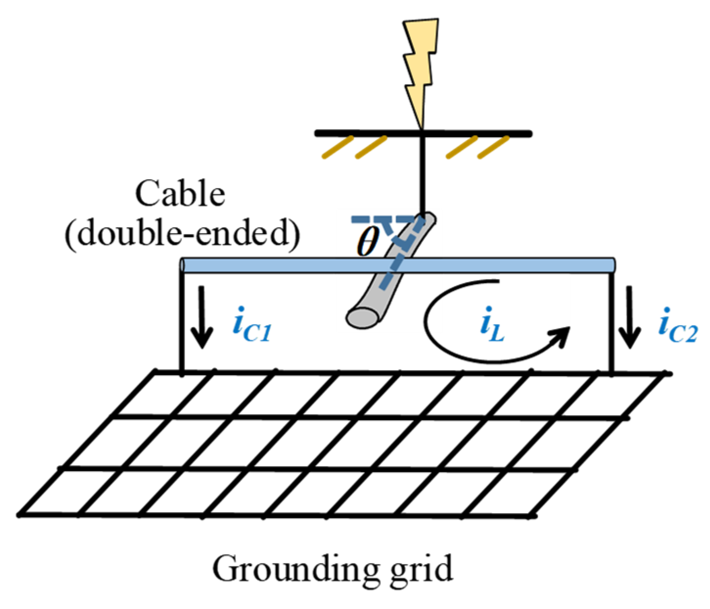
The diagram for the coupling between the discharge channel and the cable when the directly buried cable is grounded on both sides is shown in Figure 6.
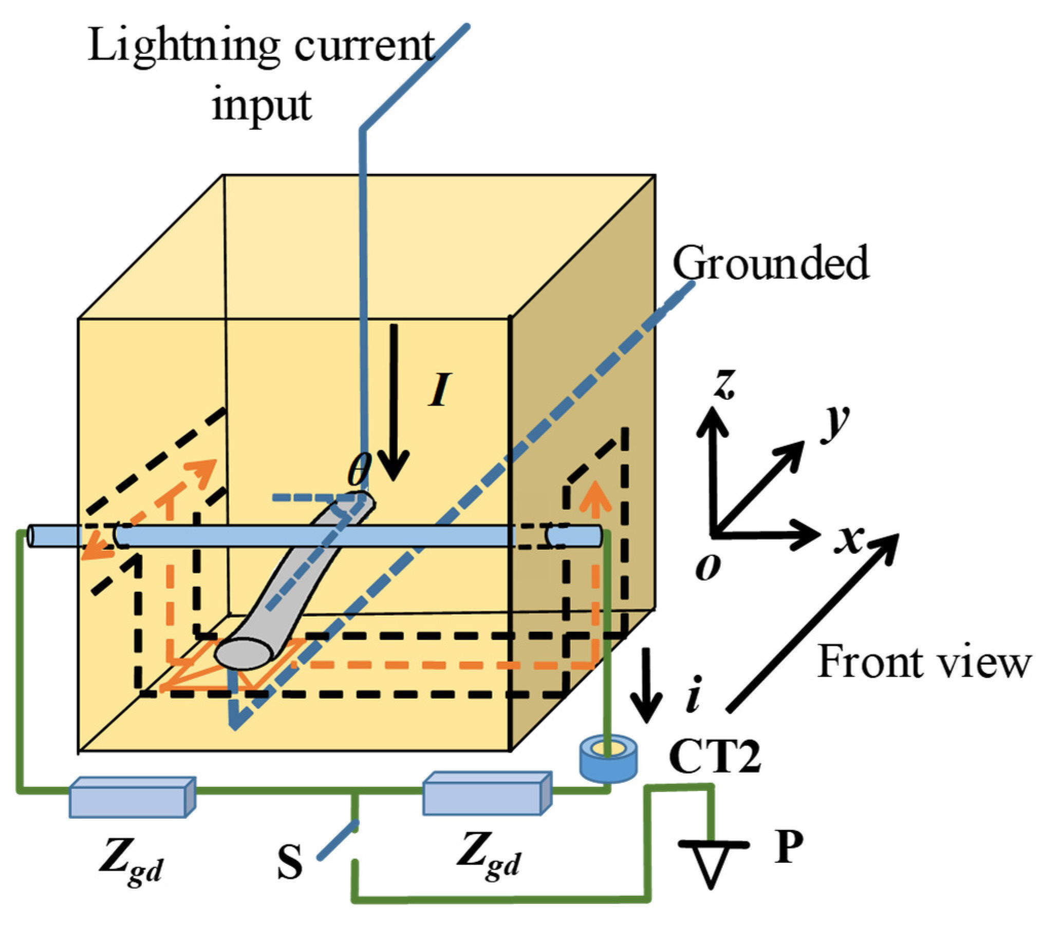
The coupling current on the shielding layer is composed of the capacitive component iC and the inductive component iL. The component iC generated by electric field coupling is divided into iC1 and iC2 and flows to the grounding system through the grounding wire. At the same time, the cable shielding layer and the grounding wires form a circuit with the connected grounding grid (hereinafter referred to as the cable shielding layer circuit). Therefore, the grounding electrode and the discharge channel will generate coupling current iL in the cable shielding layer due to inductive coupling. The scaled experiment in the DEGM is shown in Figure 7.
Compared with the experiment and observation system in Figure 3b, two 1 Ω resistors Zgd (used to simulate the grounding resistance between the two ends of the cable) are connected in series between the two ends of the cable shielding layer to form a cable shielding layer circuit in the double-end grounding mode. The size of the circuit is 30 cm × 20 cm, and it is parallel to the xoz plane. A switch S connects the two resistors and is connected to the auxiliary grounding electrode P (used to simulate cable grounding at both ends) 100 m away. The cable shielding layer current is composed of the capacitive component iC and the inductive component iL when S is closed and only contains the inductive component iL when S is open.
In addition to the coupling current component, the conduction current generated by the potential difference between the two grounding locations of the cable is also an important component of the shielding layer current, and the conduction current is dependent on the grounding locations. In case the conduction current component is small, the coupled current component cannot be ignored at this time. The factors affecting the iC current on the cable shielding layer are researched in SEGM. Therefore, an experiment in DEGM is carried out to explore the factors affecting the inductive coupling component.
The main factor affecting the inductive component iL is the magnetic flux generated in the cable shielding layer circuit when the lightning current flows through the soil discharge channel. In the double-ended grounding experiment, the variation in θ will affect the inductive coupling component by changing the magnetic flux formed in the cable shielding layer circuit, rather than primarily affecting the distances from the GCDC to the cable as in the single-ended ground experiment. Therefore, in the DEGM experiments, the soil discharge channel is fixed in parallel to the xoz plane by a copper sheet to investigate the influence of θ on the inductive component iL. In addition, in order to investigate the influence of d on the inductive component iL at the same channel angle, θ is fixed to 0°.
The direction of the current input wire and the grounding wire is perpendicular to the cable shielding layer circuit plane, so the current wire and grounding wire have little effect on the magnetic flux of the cable shielding layer circuit, and the main factor affecting the magnetic flux in the experiments is the spatial structure of the soil discharge channel.

3. Discussion

3.1. Results in SEGM

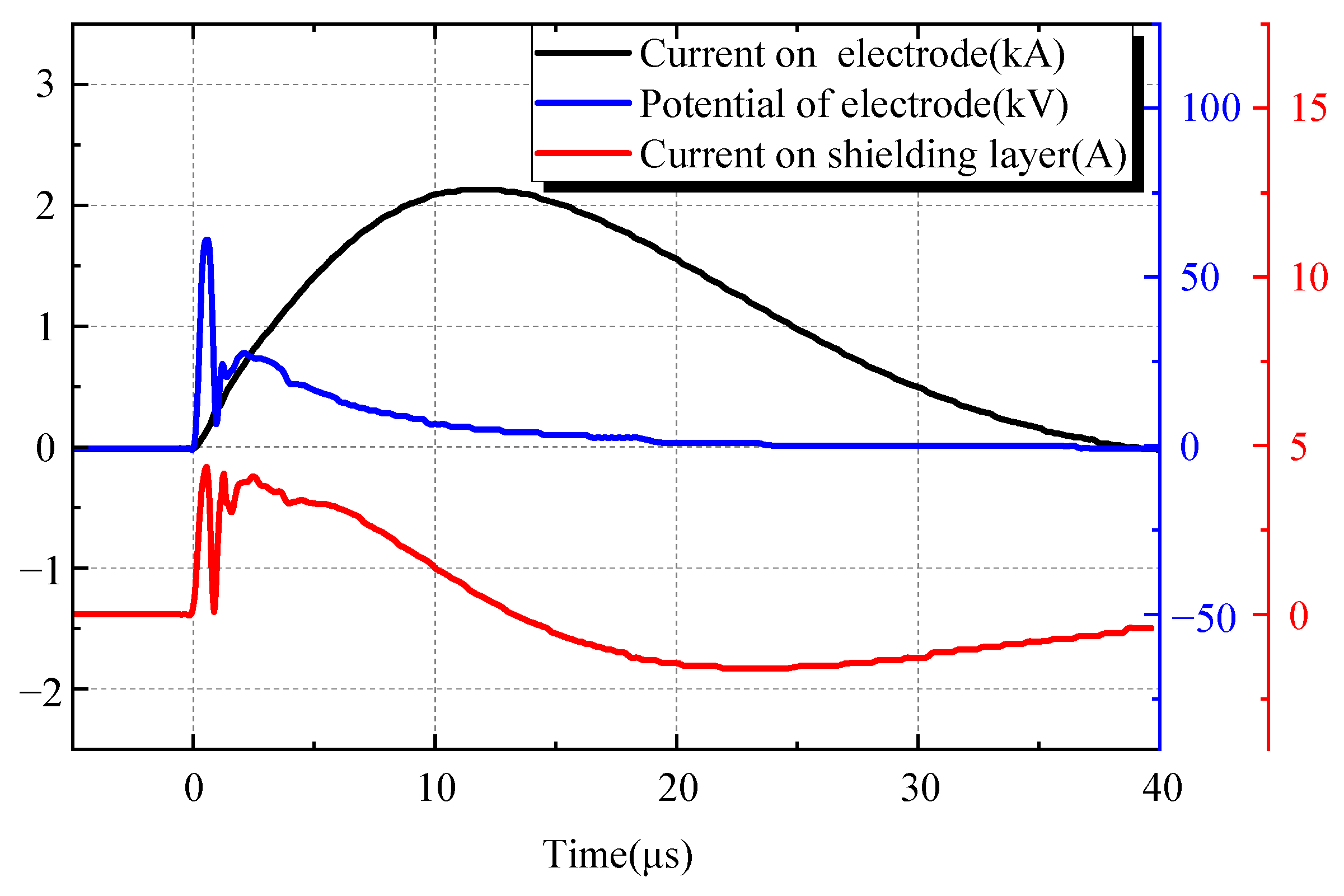
The experiment in SEGM is carried out using the design in Section 2.1 with a soil water content of 3%, salt content of 0.25%, and soil resistivity of 204 Ω·m. Figure 8 shows an example of the obtained waveforms.
Since there is no circuit, the current on the cable shield in the single-ended grounding method is mainly capacitively coupled. Therefore, it can be considered that the current on the cable shielding layer can be calculated by
iC = C∙dU/dt
where C is the equivalent coupling capacitance between the grounding electrode, soil discharge channel, and cable shielding layer.
According to the results in Figure 8, in the 0~t1 interval, U increases from zero to the critical breakdown potential, so both dU/dt and iC are greater than zero; at time t1, the soil is broken down and the electrode potential starts to decrease, so iC = 0 at t1, and then iC is negative during t1~t2. At t2~t3, the discharge channel has been formed, but the lightning current is still increasing. The grounding potential rises again with the increase in the lightning current, and a positive coupling current with an amplitude of 2.2 A is generated.

3.1.1. The Influence of Discharge Channel Structure on Capacitive Coupling Current

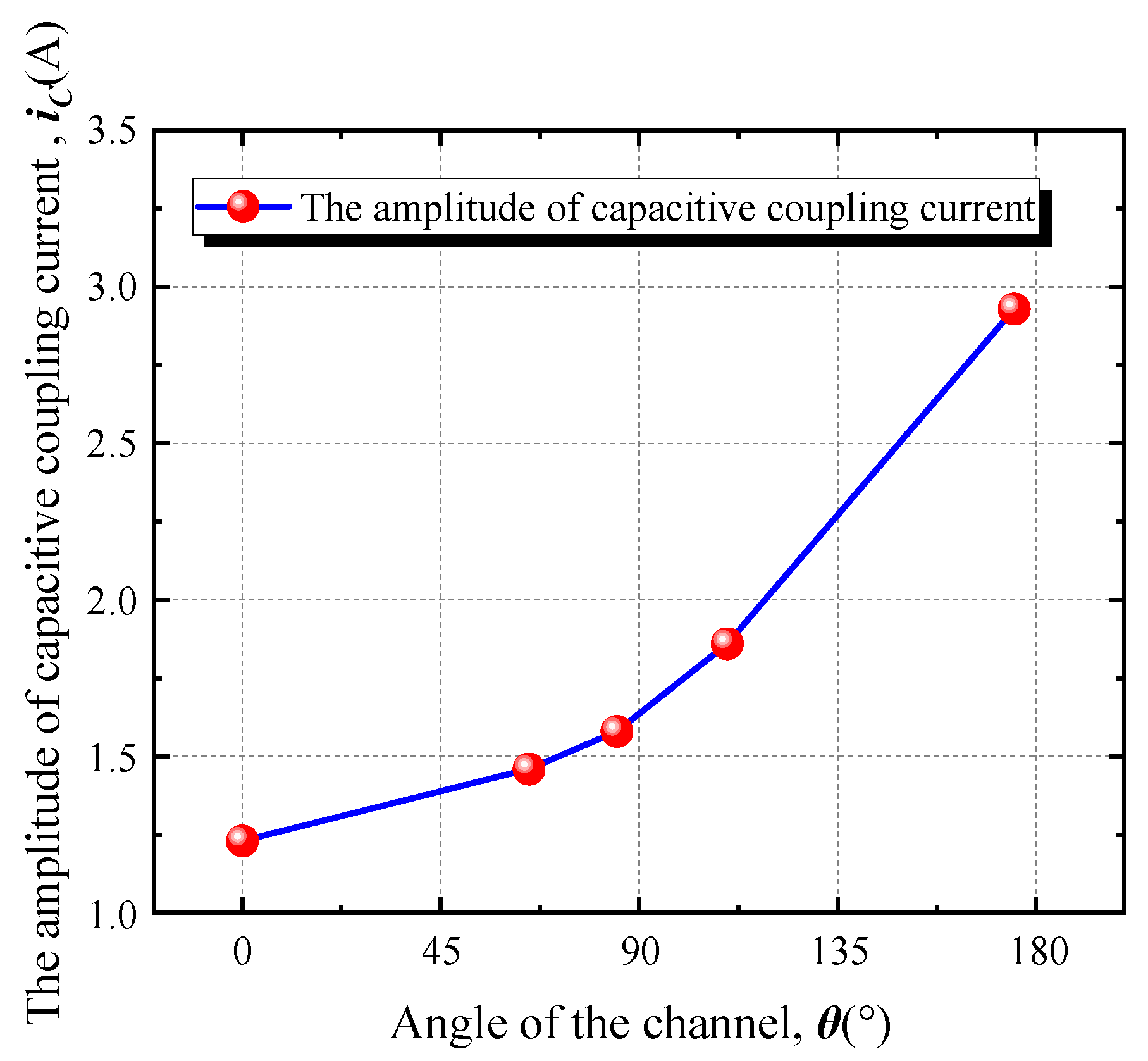
A group of experiments were performed under the conditions of a soil water content of 5%, a salt content of 0.25%, and a soil resistivity of 167 Ω·m. Five discharge channels with θ = 0°, 65°, 85°, 110°, and 175° were observed, and the captured images (front view) are shown in Figure 9. The relationship between the amplitude of the capacitive coupling current iC on the shielding layer and the θ of the soil discharge channel is shown in Figure 10.
It can be seen from Figure 10 that the amplitude of the capacitive coupling current iC rises with the increase in θ. Because the lightning current input is fixed, and the soil in each experiment is the same, dU/dt will not change significantly in different experiments. The distance between the GCDC and the cable decreases with the increase in θ, so the Cx increases with θ. Considering that the change in θ will not affect Ce, the total coupling capacitance C will increase with the increase in θ, so the amplitude of the capacitive coupling current iC increases with the increase in θ.

3.1.2. The Influence of the Water and Salt Content on the Capacitive Coupling Current

In order to investigate the influence of the water content and salt content on iC, in this paper, we prepared the soil sample with water contents of 1.5%, 3%, 5%, 7.5%, 10%, 15%, and 20%, respectively, with the salt content fixed at 0.25%. And the soil sample with salt contents of 0.05%, 0.15%, 0.25%, 0.5%, 0.75%, 0.875%, and 1% was prepared, respectively, with the water content fixed at 5%. The influence of the water and salt on the amplitude of iC is shown in Figure 11 when the soil discharge channel is 90°.
The mechanism of the salt content and water content on the electromagnetic interference process is complex. In addition to the direct influence on the soil resistivity and dielectric constant, the water content and salt content also affect the breakdown time, the current distribution in the soil, and the dielectric constant by changing the space volume of the discharge channel, the critical breakdown field strength, the channel temperature rise, the residual resistivity of the channel, and other parameters, thus indirectly affecting the electromagnetic interference. It is difficult to quantitatively analyze this process through the discharge channel images and voltage and current parameters obtained via experiments. Therefore, based on the direct influence of the water content and salt content on the soil resistivity and dielectric constant, this paper discusses their influences on the electromagnetic interference process.
It can be seen from Figure 11 that iC decreases first and then increases with changes in water content and salt content under θ = 90°. iC reaches its minimum when the water content is 15% and the salt content is 0.25%. Considering that the lightning current input is fixed, the grounding electrode potential U is dependent on the soil resistivity, which will change with the salt and water in the soil. In general, the soil resistivity will decrease as the water and salt increase, and U will decrease at the same time. Therefore, dU/dt will also decrease with increasing water and salt.
The capacitance is determined by the dielectric constant of the medium when the spatial structure of the discharge channel is fixed. The dielectric constant of soil is also dependent on the water and salt content of soil, and in general, the dielectric constant of soil increases with the increase in both of them [30]. Therefore, with the increase in soil water and salt content, the equivalent coupling capacitance, C, gradually increases in the experiments, while the dU/dt decreases at the same time. The combined effect of the two factors means that iC shows the trend in Figure 11.
The increase in water content and salt content has a saturation effect on the decrease in soil apparent resistivity. It can be seen from Figure 11 that when the salt content is less than 0.25%, increasing the soil salt content means that the peak value of the coupling current decreases rapidly, which indicates that increasing the salt content at this time plays a major role in reducing the soil resistivity. As the salt content continues to increase, before it is greater than 0.75%, the peak change in the capacitive coupling current is small, indicating that the decrease in soil resistivity and the increase in dielectric constant offset each other. When the salt content is greater than 0.75%, the soil salt content is close to saturation. At this time, increasing the salt content will not significantly reduce the soil resistivity, but the continuous increase in the soil dielectric constant makes the coupling current peak rise rapidly. The change trend in the capacitive coupling current caused by the increase in water content is similar to that for the salt content. When the water content is less than 10%, the decrease in soil resistivity caused by the water content is the main factor in the change in the capacitive coupling current. With the gradual increase in water content, the reduction in soil resistivity tends to be saturated. When the water content is greater than 15%, the increase in water content leads the capacitive coupling current to gradually increase by affecting the soil dielectric constant. It should be noted that the porosity of sand is much greater than that of soil, so more water is needed to reach the saturation value than in conventional soil.
For the cable in the single-ended grounding mode, the current on the cable shielding layer is mainly a capacitive coupling current. The distance between the soil discharge channel and the cable and the water content and the salt content of the soil will have a great impact on the coupling current on the shielding layer. However, the water content and salt content of the soil are not linear to the coupling current, as shown in Figure 11. Although the ground potential rise can be presumed to be smaller in the case of higher soil water and salt contents, it does not necessarily produce a lower coupling current. In addition, a huge workload is required to obtain a small capacitive coupling current by monitoring and regulating the water content and salt content of the soil throughout the substation. As mentioned above, the narrow soil discharge channel can be considered an extension of the grounding electrode, which may be as long as several meters. The safe distance between the cable and the independent grounding electrode specified in the design standard is based on the assumption that the lightning current is uniformly dispersed in all directions in the soil. Therefore, in order to ensure the operation of the secondary cable, a greater safety distance is necessary. In addition, it can be seen from Figure 10 and Figure 11 that the coupling current generated by the discharge channel developing toward the cable is larger, because such channels are closer to the cable. Considering that the discharge mainly occurs at the tip of the grounding device and higher water content and salt content are beneficial to soil discharge, the development direction of the discharge channel can be induced by using the asymmetric grounding device and the resistance reduction scheme in specific areas.

3.2. Results in DEGM

The experiments in DEGM are performed according to the arrangement shown in Figure 7. In the experiment, the switch S is always closed, the soil water content is 3%, the salt content is 0.25%, and the soil resistivity is 204 Ω·m. A set of waveforms obtained under the above conditions are shown in Figure 12. The main components of the coupling current on the shielding layer include the capacitive current iC and the inductive current iL. Using the same arrangement but keeping S open, a set of waveforms is obtained, as shown in Figure 13.
The obtained shielding layer coupling current is mainly the inductive coupling current iL. Comparing Figure 8 with Figure 12 and Figure 13, it can be found that the waveform of the coupling current of the shielding layer in DEGM can be regarded as the superposition of the capacitive component iC and the inductive component iL.
Since the factors that affect the capacitive coupling current have been explored in SEGM, this section will investigate the factors affecting the inductive coupling current iL. Therefore, all the following experiments are carried out with switch S open. The main component of the shielding layer current is the inductive coupling current when S is open. The inductive coupling voltage can be calculated by (2)
uL = M∙dI/dt
where M is the mutual inductance of the grounding electrode, the soil discharge channel, and the cable shielding layer circuit.
The self-inductance of the cable shielding layer circuit can be ignored because of its small size. Since two 1 Ω resistors are connected in series in the circuit in the cable shielding layer, the inductive coupling current iL is half of the induced voltage uL. It can be seen from Figure 13 that the derivative of the grounding electrode current and the shielding layer current is linear; that is, M is almost constant during the discharge process.

3.2.1. The Influence of the Discharge Channel Structure on the Inductive Coupling Current

In order to investigate the influence of the channel structure on inductive coupling, experiments are carried out with θ and d as variables. The content of water and salt used in the experiments is 5% and 0.25%, respectively, and the soil resistivity is 167 Ω·m. Five discharge channels, with θ = 0°, 65°, 90°, 120°, and 180°, are obtained. Figure 14 shows the captured X-ray images (front view), and the amplitude of the inductive component iL of the shielding layer is shown in Figure 15.
It can be seen from Figure 15 that the amplitude of iL decreases with the increase in the angle when θ ≤ 90°, while the trend is opposite when 90° < θ ≤ 180°. The experiments on the influence of the distance d on the coupling current iL are carried out with θ = 0°. The X-ray top view of four channels with different d are shown in Figure 16, and the relationship between the amplitude of iL and d is shown in Figure 17. Figure 17 shows that iL increases with d and the amplitude of iL may vary up to tens of times in different spatial structures of soil discharge channels.
The lightning current input used in the experiments is fixed, so dI/dt will not change greatly in different experiments. Therefore, the main factor affecting the amplitude of iL is the change in mutual inductance M caused by the spatial structure of the discharge channel. The three-dimensional structure of the channel will affect the magnetic flux change caused by the current flowing in the cable shielding layer circuit significantly. When θ = 0° or 180°, the impact current flowing through the channel causes the largest change in the magnetic flux in the cable shielding layer circuit, so the mutual inductance M is larger. When θ = 90°, the channel runs vertically downward, so the electrode current can hardly cause the magnetic flux change in the cable shielding layer circuit, and M reaches the minimum at this time. With the decrease in distance d, the number of magnetic lines that intersect with the cable shielding layer circuit increases, and the mutual inductance M will increase.

3.2.2. The Influence of Water and Salt Content on the Inductive Coupling Current

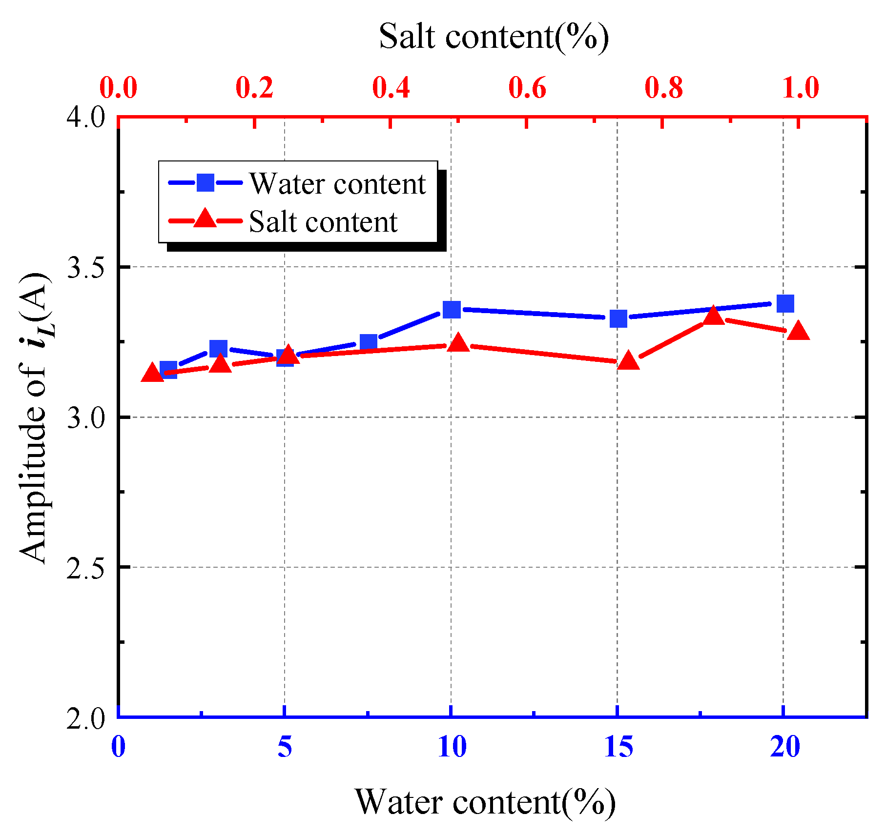
In order to investigate the influence of the water content and salt content on the inductive coupling current iL, the soil sample is the same as that in Section 3.1.2. The influence of the water content and salt content on the amplitude of iL is shown in Figure 18 with θ = 0°.
It can be seen from Figure 18 that the change in water content and salt content hardly affects the amplitude of the inductive coupling current iL. Since the lightning current input is fixed, the dI/dt will not change greatly in different experiments. In addition, the mutual inductance M is only related to the permeability of the medium when the circuit does not change. The soil, salt, and water are not ferromagnetic substances, so the change in water content and salt content hardly affect the soil permeability, resulting in the mutual inductance M being unchanged. As mentioned above, although the soil water content and salt content will not have a direct impact on the permeability, the water content and salt content also affect the breakdown time and the current distribution in the soil by changing the space volume of the discharge channel, the critical breakdown field strength, the channel temperature rise, the residual resistivity of the channel, and other parameters, thus indirectly affecting the electromagnetic interference. Therefore, iL rises slowly with the increase in water content and salt content.
For the cables in double-ended grounding mode, in addition to the capacitive coupling current, the coupling current on the shielding layer also includes the inductive coupling current component and the conductive current component caused by the potential difference between the grounding points. The conductive current component is difficult to control, but the induced current component is related to the magnetic flux through the cable-grounding device circuit, which is dependent on the distance and angle between the discharge channel and the circuit. Therefore, it is still feasible to suppress electromagnetic interference by reducing resistance in specific areas and installing asymmetrical grounding devices to induce the development direction of discharge channels.

4. Conclusions

In this paper, the electromagnetic interference in the concentrated soil discharge channel formed by the lightning current flowing through the independent grounding electrode on the adjacent buried cable is experimentally explored. The results of the scaled experiment show that a centralized soil discharge channel will be formed at the tip of the independent grounding electrode when the lightning current passes through it, which will cause electromagnetic interference to the nearby directly buried cable. The grounding mode of the cable shielding layer, the structure of the discharge channel, and the water content and salt content of the soil will affect the coupling current on the shielding layer. The conclusions obtained in the scaled experiments are as follows:
1.
The coupling pattern in the shielding layer current is dependent on cable shielding layer grounding modes: the capacitive coupling current is the main component of the shielding layer current in SEGM, while the shielding current is composed of capacitive coupling and inductive coupling in DEGM.
2.
When the cable is single-ended grounded, the capacitive coupling current is dependent on the distance between the geometric center of the discharge channel and the buried cable. The capacitive coupling current increases with the decrease in the distance, resulting in a difference of about 2.5 times the current amplitude. The water content and salt content will have an influence on the capacitive coupling process by affecting the dielectric constant and soil resistivity. The current decreases first and then increases with the increase in water and salt.
3.
For magnetic field coupling (the inductive coupling current), the discharge channel will have an influence on the inductive coupling process by affecting both the distance and angle between the discharge channel and cable shielding layer circuit. The water content and salt content hardly affect the amplitude of the inductive coupling current.
4.
The water content, the salt content, and the relative position of the discharge channel and the cable will affect the coupling current on the cable shielding layer. The influence of the water content and salt content on the capacitive coupling current is nonlinear, and they have little effect on the inductive coupling current. Therefore, it is not recommended that the electromagnetic interference of the cable be weakened by regulating the water content and salt content. The distance between the channel and cable and the relative direction of the cable or the cable-grounding device circuit will significantly affect the shielding coupling current. Therefore, it may be a better way of weakening the electromagnetic interference by setting an asymmetric grounding device or reducing the resistance of the soil in a specific area to induce the development direction of the discharge channel, thereby weakening the electromagnetic interference.

Author Contributions

The authors gratefully acknowledge the contributions as following: Q.C. perform the experiments; T.Y. analyzed the data and wrote the manuscript; R.F. and W.Z. read and edit the manuscript. All authors have read and agreed to the published version of the manuscript.

Funding

Funded by the special cost of Sichuan Economic Research Institute of State Grid in 2024 (State Grid Sichuan 2024 UHV transmission engineering geology and lightning multi-disaster disaster-causing mechanism research technical service).

Data Availability Statement

All data generated or used during the study are reasonably available from the corresponding author.

Conflicts of Interest

Authors Rongquan Fan and Wenhui Zeng were employed by the company State Grid Sichuan Province Electric Power Company Electric Power Economy Technology Research Institute. The remaining authors declare that the research was conducted in the absence of any commercial or financial relationships that could be construed as a potential conflict of interest.

References

  1. Cooray, V.; Rubinstein, M.; Rachidi, F. Field-to-transmission line coupling models with special attention to the Cooray–Rubinstein approximation. IEEE Trans. Electromagn. Compat. 2021, 63, 84–493. [Google Scholar] [CrossRef]
  2. Zhang, Y.; Liao, C.; Shang, Y.P.; Du, W.; Huan, R.; Ye, Z.H. Analysis of the field-line coupling of the transmission line above an orthogonal ground plane through electromagnetic reciprocity theorem. IEEE Trans. Electromagn. Compat. 2020, 62, 580–588. [Google Scholar] [CrossRef]
  3. Liu, Z.R.; Cui, Y.G.; Zhang, B.; He, J.L. Measurement of multipath transients in secondary cables near a 500 kV gas-insulated switchgear during operations. IEEE Trans. Power Del. 2023, 38, 917–925. [Google Scholar] [CrossRef]
  4. IEEE Std 80-2013 (Revision of IEEE Std 80-2000/Incorporates IEEE Std 80-2013/Cor 1-2015); IEEE Guide for Safety in AC Substation Grounding. IEEE: Minneapolis, MN, USA, 15 May 2015; pp. 1–226.
  5. Liew, A.C.; Darveniza, M. Dynamic model of impulse characteristics of concentrated earths. Electr. Eng. Proc. Inst. 1974, 121, 123–135. [Google Scholar] [CrossRef]
  6. Geri, A. Behavior of grounding systems excited by high impulse currents: The model and its validation. IEEE Trans. Power Del. 1999, 14, 1008–1017. [Google Scholar] [CrossRef]
  7. Gao, Y.Q.; He, J.L.; Zou, J.; Zeng, R.; Liang, X. Fractal simulation of soil breakdown under lightning current. J. Electrost. 2004, 61, 197–207. [Google Scholar] [CrossRef]
  8. Zeng, R.; Gong, X.H.; He, J.L.; Zhang, B.; Gao, Y.Q. Lightning impulse performances of grounding grids for substations considering soil ionization. IEEE Trans. Power Del. 2008, 23, 667–675. [Google Scholar] [CrossRef]
  9. Rakov, V.A.; Uman, M.A.; Rambo, K.J.; Fernandez, M.I.; Fisher, R.J.; Schnetzer, G.H.; Thottappillil, R.; Eybert-Berard, A.; Berlandis, J.P.; Lalande, P.; et al. New insights into lightning processes gained from triggered-lightning experiments in Florida and Alabama. J. Geophys. Res. Atmos. 1998, 103, 14117–14130. [Google Scholar] [CrossRef]
  10. Rakov, V.A. Triggered Lightning; Springer: Dordrecht, The Netherlands, 2009; pp. 40–47. [Google Scholar]
  11. Sima, W.X.; Luo, D.H.; Yuan, T.; Liu, S.W.; Sun, P.T. Study on the image observation method and characteristics of soil discharge process under multiple impulse currents. IEEE Trans. Power Del. 2018, 33, 2125–2134. [Google Scholar] [CrossRef]
  12. Luo, D.H.; Sima, W.X.; Yuan, T.; Sun, P.T.; Chen, W.; Wang, J. Influence-factor analysis and parameter calculation of soil discharge and recovery characteristics under successive impulse currents. IEEE Trans. Power Del. 2019, 34, 514–523. [Google Scholar] [CrossRef]
  13. Wang, J.P.; Liew, A.C.; Darveniza, M. Extension of dynamic model of impulse behavior of concentrated grounds at high currents. IEEE Trans. Power Del. 2005, 20, 2160–2165. [Google Scholar] [CrossRef]
  14. Mousa, A.M. The soil ionization gradient associated with discharge of high currents into concentrated electrodes. IEEE Trans. Power Del. 1994, 9, 1669–1677. [Google Scholar] [CrossRef]
  15. Mazzetti, C.; Veca, G.M. Impulse behavior of ground electrodes. IEEE Trans. Power Appar. Syst. 1983, 102, 3148–3154. [Google Scholar] [CrossRef]
  16. Colominas, I.; Navarrina, F.; Casteleiro, M. Analysis of transferred Earth potentials in grounding systems: A BEM numerical approach. IEEE Trans. Power Del. 2005, 20, 339–345. [Google Scholar]
  17. Nahman, J.M. Earthing effects of uncoated underground cable and transferred potentials. Electr. Eng. 1996, 79, 55–60. [Google Scholar] [CrossRef]
  18. Vance, E.F. Coupling to Shielded Cables; John Wiley & Sons: New York, NY, USA, 1978; pp. 1–183. [Google Scholar]
  19. Zhang, G. Analysis of Coupling Function from External Transient Electromagnetic Field to Shielded Cables. Master’s Thesis, Harbin Institute of Technology, Haerbin, China, 2009. [Google Scholar]
  20. Li, B. Analysis on Interference Coupling Characteristic of Cable in Seconary of Substation Due to Lightning Impulse. Master’s Thesis, Shenyang University of Technology, Shenyang, China, 2014. [Google Scholar]
  21. Tatematsu, A.; Rachidi, F.; Rubinstein, M. Three-dimensional FDTD based simulation of induced surges in secondary circuits owing to primary circuit surges in substations. IEEE Trans. Electromagn. Compat. 2021, 63, 1078–1089. [Google Scholar] [CrossRef]
  22. Haddad, F.; Bayard, B.; Sauviac, B. Low-frequency relation between transfer impedance and shielding effectiveness of braided cables and grid shields. IEEE Trans. Electromagn. Compat. 2020, 62, 2423–2430. [Google Scholar] [CrossRef]
  23. Zhang, B.; Li, C.R.; Liu, Z.R.; He, J.L. Analysis of Transient in Secondary Cable Due to a Direct Lightning Strike on Grounding Grid. IEEE Trans. Electromagn. Compat. 2023, 65, 1183–1190. [Google Scholar] [CrossRef]
  24. Yeung, C.K.; Wang, J.G.; Zhou, M.; Zhao, W.H.; Huang, W.X.; Cao, J.X.; Cai, L.; Du, Y.P. Affection of shielding methods on the characteristics for cable coupled to lightning impulse magnetic field. Electr. Power Syst. Res. 2023, 226, 109802. [Google Scholar] [CrossRef]
  25. Liu, S.W.; Sima, W.X.; Yuan, T.; Luo, D.H.; Bai, Y.; Yang, M. Study on X-ray imaging of soil discharge and calculation method of the ionization parameters. IEEE Trans. Power Del. 2017, 32, 2013–2021. [Google Scholar] [CrossRef]
  26. IEEE Standard 1100-1999; Recommended Practice for Powering and Grounding Electronic Equipment. IEEE: New York, NY, USA, 22 March 1999; pp. 1–408.
  27. Royer, C.; Dorison, E.; Anderson, N.; Benato, R.; Brijs, B.; Chang, K.W.; Falconer, A.; Fernandez, S.; Gudmunsdottir, U.S.; Li, J.; et al. Cable Systems Electrical Characteristics; Technical Report for CIGRE Technical Brochure N°531; CIGRE: Paris, France, 2013. [Google Scholar]
  28. ASTM G57-06; Standard Test Method for Field Measurement of Soil Resistivity Using the Wenner Four-Electrode Method. ASTM International: West Conshohocken, PA, USA, 2012.
  29. Sima, W.X.; Liu, S.W.; Yuan, T.; Luo, D.H.; Wu, P.; Zhu, B. Experimental study of the discharge area of soil breakdown under surge current using X-ray imaging technology. IEEE Trans. Ind. Appl. 2015, 51, 5343–5351. [Google Scholar] [CrossRef]
  30. Zhang, P. Analysis to Effects of Main Factors on Dielectric Properties of Soil. Master’s Thesis, Northwest A&F University, Xianyang, China, 2013. [Google Scholar]
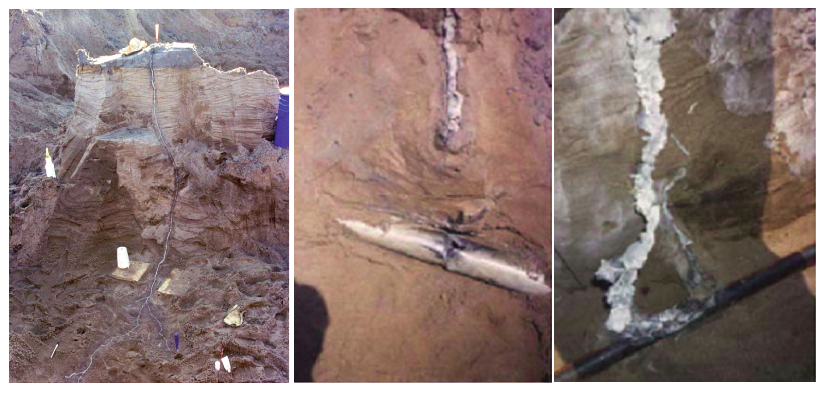
Figure 1. Soil discharge channel observed by Rakov [10].
Energies 17 03852 g001
Figure 2. Capacitive coupling of the cable in SEGM.
Energies 17 03852 g002
Figure 3. Platform and observation system (SEGM).
Energies 17 03852 g003
Figure 4. Experimental arrangement in SEGM. (a) Soil sample, (b) cable layout, (c) cable parameters.
Energies 17 03852 g004
Figure 5. Examples of X-ray images. (a) Front view, (b) left view, (c) top view, (d) the reconstructed model.
Energies 17 03852 g005
Figure 6. Coupling mode when the cable is grounded at two ends.
Energies 17 03852 g006
Figure 7. Cable layout in DEGM.
Energies 17 03852 g007
Figure 8. A set of waveforms in the shield layer.
Energies 17 03852 g008
Figure 9. The X-ray images of discharge channel in SEGM. (a) θ = 0°, (b) θ = 65°, (c) θ = 85°, (d) θ = 110°, (e) θ = 175°.
Energies 17 03852 g009
Figure 10. The influence of θ on the capacitive coupling current.
Energies 17 03852 g010
Figure 11. The influence of water and salt contents on iC.
Energies 17 03852 g011
Figure 12. A set of waveforms in DEGM with S closed.
Energies 17 03852 g012
Figure 13. A set of waveforms in DEGM with S open.
Energies 17 03852 g013
Figure 14. The X-ray pictures from the discharge channel angle test under double-ended grounding. (a) θ = 0°, (b) θ = 65°, (c) θ = 90°, (d) θ = 120°, (e) θ = 180°.
Energies 17 03852 g014
Figure 15. The influence of θ on the inductive coupling current.
Energies 17 03852 g015
Figure 16. X-ray images of different distances d in double-ended grounding (vertical view). (a) d = 0.4 cm, (b) d = 3.6 cm, (c) d = 4.9 cm, (d) d = 6.5 cm.
Energies 17 03852 g016
Figure 17. The influence of d on the inductive coupling current.
Energies 17 03852 g017
Figure 18. The influence of the soil water and salt content on the inductive coupling current.
Energies 17 03852 g018
Disclaimer/Publisher’s Note: The statements, opinions and data contained in all publications are solely those of the individual author(s) and contributor(s) and not of MDPI and/or the editor(s). MDPI and/or the editor(s) disclaim responsibility for any injury to people or property resulting from any ideas, methods, instructions or products referred to in the content.