Article

Justifying and Implementing Concept of Object-Oriented Observers of Thermal State of Rolling Mill Motors

by
Stanislav S. Voronin
1,
Andrey A. Radionov
1,
Alexander S. Karandaev
1,
Ivan N. Erdakov
2,*,
Boris M. Loginov
3 and
Vadim R. Khramshin
3
1
Department of Automation and Control, Moscow Polytechnic University, 107023 Moscow, Russia
2
Department of Metal Forming, South Ural State University, 454080 Chelyabinsk, Russia
3
Power Engineering and Automated Systems Institute, Nosov Magnitogorsk State Technical University, 455000 Magnitogorsk, Russia
*
Author to whom correspondence should be addressed.
Energies 2024, 17(16), 3878; https://doi.org/10.3390/en17163878
Submission received: 19 June 2024 / Revised: 21 July 2024 / Accepted: 2 August 2024 / Published: 6 August 2024
(This article belongs to the Section J: Thermal Management)

Abstract

:
Implementing the IIoT concept in industry involves the development and implementation of online systems monitoring the technical state of electromechanical equipment. This is achieved through the use of digital twins and digital shadows (object state observers). The tasks of mastering new rolling profiles and optimizing plate mill rolling programs require improved methods for calculating equivalent motor currents and torques. Known methods are generally based on calculations using smoothed load diagrams, which are assumed to be identical for the upper and lower main drive (UMD and LMD) rolls. These methods do not consider the differences in actual loads (currents or torques) in steady rolling states. Experiments performed on the 5000 plate mill have shown that due to speed mismatches, the UMD and LMD torques differ three times or more. This causes overheating of the more heavily loaded motor, insulation life reduction, and premature failure. Therefore, the problem of developing and implementing techniques for monitoring the load and thermal regimes of motors using digital observers is relevant. The paper’s contribution is the first justification of the concept of object-oriented digital shadows. They are developed for specific classes of industrial units using open-source software. This research justifies a methodology for assessing motor load and temperature by processing arrays of motor currents or torques generated during rolling. An equivalent load observer and a temperature observer were proposed and implemented using Matlab-Simulink resources. The algorithm was implemented on the mill 5000 and tuned using an earlier-developed virtual commissioning methodology with digital twins. Thermal regimes were studied, proving that torque alignment ensures equal motor temperatures. The proposed considerations contribute to the development of the theory and practice for creating digital systems to monitor the technical condition of electromechanical and mechatronic systems and implementing the Industry 4.0 concept at industrial enterprises.

1. Introduction

One of the purposes of implementing the Industrial Internet of Things, IIoT, a concept in industrial enterprises, is to reduce maintenance costs by introducing diagnostic monitoring techniques and systems. This problem is solved by implementing modern technologies based on digital twins (DTs) and digital shadows (DSs). DSs are implemented as state observers of electromechanical and mechatronic systems [1,2]. This direction is highly demanded for metallurgical production units, especially rolling mills. These units provide the manufacture of finished products for metallurgical enterprises, making their reliability essential for the rhythmic operation of the production chain. Of equal importance is the task of reducing power consumption of the production line since it affects product costs. According to [3], “as Industry 4.0 implementation progresses and the manufacturing process becomes more digital, the digital twin will become invaluable for testing and simulating new parameters and design options”. This conclusion can also be applied to digital shadows, whose implementation is necessary for solving electromechanical and mechatronic equipment condition monitoring problems [4].
By analogy with object-oriented digital twins justified in [5], the paper proposes introducing the concept of an object-oriented observer of coordinates or state of a technical system. This term refers to a digital shadow, which, according to the generally accepted definition, ensures an automated data flow from a physical object to a digital one [6]. Accordingly, in DS, the physical object’s state determines the current state of the digital object, making real-time monitoring of the real object’s state relatively simple. An object-oriented DS is intended for a specific technological object and is not a universal software product. It is implemented based on open-source software. Such observers are supposed to be used to monitor the state of equipment of complex industrial units, including rolling mills.
Object-oriented coordinate observers have been proposed to calculate (restore) motor temperatures by monitoring equivalent load parameters. As is known, load regime analysis is used to choose motors for various electric drives, including rolling mill motors. Methods for calculating equivalent (effective or root mean square) torques, currents, or powers are applied, where the calculation is a particular case of the average loss method. Subsequently, during operation, the calculation of equivalent parameters is not used, so load and thermal regimes are not evaluated. However, monitoring the load and thermal regimes of motors during rolling is relevant for operational rolling mills. This problem should be addressed in the following cases:
  • When mastering new rolling profiles;
  • To optimize speed and load regimes of electric drives, including for increasing productivity and rolling rhythm regularity [7];
  • To optimize the distribution of compressions and loads across stands for continuous mills or passes for reversing mills, aiming, among other things, to reduce energy costs [8,9];
  • To improve the load alignment system for the upper and lower rolls of the stand.
Thermal assessment is required when developing rolling programs for new profiles from hard-to-deform steel grades. Such a situation occurs at plate mills when mastering the production of blanks from special cold-resistant steels for large-diameter pipes and wide-strip mills when manufacturing long pipe blanks. In the latter case, it turns out to be essential to assess load and thermal regimes considering the actual load distribution across stands (or motors of one stand) according to the developed rolling programs. Obviously, this can be most effectively done through automated online monitoring of equivalent loads and motor temperatures. The purpose of this analysis is to assess the feasibility of manufacturing new profiles without exceeding permissible loads. In other words, it is a problem of evaluating the constraints imposed by the drive on the process. Its solution is also relevant for other production facilities, particularly lifting and transport machines [10], robotic complexes [11], etc.
Monitoring load and thermal motor regimes are in high demand for rolling mills with individual roll drives. These include plate mills and roughing stands of hot rolling wide-strip mills. A simplified kinematic diagram for the rolling 5000 mill’s main drive is presented in Figure 1. Hereinafter, the abbreviation “5000” means the length of a work roll barrel of a mill stand, which determines the maximum width of a sheet or strip rolled. This mill feature is generally accepted and is used within the documentation and literary sources applied. The individual electric drive allows for the independent control of roll speeds, producing the ski effect of the workpiece front end at the stand exit. This facilitates further moving the workpiece without hitting the roller table rolls and reducing production accidents [12,13] (this issue is described below in Section 3.1).
The need to assess equivalent power parameters arises for unequal UMD and LMD motor loads. Load inequality is commonly due to speed differences between these motors. Experiments on the 5000 mill have shown that a ±5% speed difference causes a two-fold difference in motor torques. The primary cause is misalignment specifically set for the ski formation. On the 5000 mill, initial speed misalignment can make up to 10% (rarely 15%) of the steady rolling speed. This mismatch is set by the load distribution controller, which is discussed below in Section 3.1. This causes three-fold or higher motor torque differences. This has been confirmed by load and thermal regime studies with different ski formation settings, described below in Section 3.2 and Section 6. Moreover, several factors affecting speed differences are independent of the UMD and LMD motor speed ratios and cannot be resolved by the drive. These include temperature gradients across the workpiece thickness, upper and lower roll diameter differences, rolling levels, and other factors. These factors are analyzed in [14,15] and are not discussed herein.
The literary sources pay considerable attention to calculating and forecasting rolling mill drive loads. However, literature reviews and plate mill operation practice show that existing techniques for calculating equivalent loads do not consider the aforementioned torque difference. The calculations are based on simplified load diagrams, the same for both roll motors [16,17]. These techniques are used to calculate power and choose a motor at the drive design stage but are not reliable for assessing real loads and analyzing thermal regimes of operational rolling mill motors.
In this connection, the task is to develop a technique for calculating equivalent motor loads based on actual torques or currents measured in real-time or by data arrays pre-formed during rolling. Actual torques, currents, or powers of UMD and LMD motors should be measured in each pass for each batch of sheets at a specified interval. This is necessary for implementing new rolling programs when expanding the mill’s range or optimizing existing programs.
An equally important problem is temperature monitoring, which is required to prevent overheating, which affects machine conditions and causes insulation degradation. Excessive heating of stator and rotor windings and the stator magnetic circuit deteriorates the performance of the electric machine and limits its lifespan [18]. According to [19], increasing the motor’s operating temperature by 10 °C actually halves its lifespan. According to [20], “the temperature of the stators and rotors of large machines is important for both short-term protection and long-term monitoring of their conditions”. Herewith, installing temperature sensors in all machine units, especially the rotating part, is technically complex and requires significant costs. This opinion is shared by the authors [21,22,23]. This is due to the complexity of developing and installing special sensors, in particular, within a motor rotor. Therefore, developing and implementing digital observers for the equivalent loads of rolling mill drive motors with individual speed control of the upper and lower rolls is relevant. Developing an automated motor temperature control system for UMD and LMD is also relevant. The proposed solutions should be applicable for restoring these parameters by processing coordinates recorded during the rolling of one or several batches of sheets or strips.
It should also be noted that unequal distribution of loads onto motors of upper and lower rolls of the rolling stand has a negative impact on the loss of electrical energy and, accordingly, on energy consumption within rolling. Taking into account the fact that rolling production accounts for 16 to 20% of the energy consumed by the metallurgical industry, and the potential for energy saving in electricity exceeds 21%, the search for reserves to reduce energy consumption at rolling is relevant. In this regard, it is relevant to consider the problem of increasing the efficiency of electric drives by equalizing the loads of UMD and LMD motors involved.
This paper is dedicated to solving these problems.

2. Literature Review

2.1. Motor Thermal Regime Monitoring

Many publications stress the relevance of online monitoring of motor thermal states. Thus, Ref. [21] provides a modern review and formulates further problems for the thermal monitoring of various motors. It is noted that temperature measurement is crucial for protecting motors from overheating while maximizing power and torque. To optimize the dynamic performance limits of a motor during operation, its temperature should be known in real time. The main monitoring types analyzed include sensor-based and model-based temperature monitoring. It is concluded that assessment techniques based on mathematical models have gained significant importance in both industry and academia, focusing on simplified computational monitoring methods suitable for implementation on low-cost embedded control hardware. Ref. [22] is dedicated to a comparative analysis of various observers designed for simultaneous temperature and thermal loss assessment. It notes that online motor temperature monitoring is essential for drive safety under dynamic loads. Thereat, the number and location of temperature sensors are often limited by installation constraints, and most motor parts’ temperatures cannot be measured directly. An observer using a motor thermal circuit model is proposed for real-time instantaneous temperature distribution assessment.
One of the early publications on motor temperature monitoring notes that installing temperature sensors at critical points often leads to significant control delays and complex signal transmission when measuring in the rotor [23]. An observer for temperature estimation in electric machines based on a thermal model implemented on a microcomputer is presented. Experimental outcomes are shown for three different machine types, including a 3500 kW rolling mill motor. It is noted that the increasing use of microcomputers in drive control implies the use of thermal models for assessing the temperatures of electric machine windings. The development of temperature observers for rolling mill motors is also covered in [24,25]. The problems of forecasting loads and motor heating assessment are addressed in [26,27] for tandem cold rolling mills and [28] for rolling titanium-aluminum alloy.
Later publications consider motor temperature observers based on various principles. Ref. [18] proposes a virtual temperature sensor (VTS) to estimate temperature at different locations within an electric machine. In essence, it uses a digital shadow (a dynamic model-based observer) requiring only one temperature sensor placed in an accessible part of the machine. The authors claim that the VTS may provide useful real-time temperature estimates at various points despite simulation uncertainties and unknown initial temperatures. A large number of developments concern traction motors of vehicles, particularly observers based on the measurement of magnetic flux or flux linkage. Ref. [29] proposed an observer using the temperature dependence of permanent magnet flux. Developing this idea, Ref. [30] presented an advanced technique for determining the rotor temperature of a synchronous machine during dynamic operations. The development of thermal state observers for synchronous motors with permanent magnets is also covered in [31,32,33]. In [34], a simplified thermal model and an online temperature estimation technique for these motors are developed. It is noted that monitoring critical temperatures in synchronous motors is crucial for improving reliability. A state equation-based estimation scheme and a Kalman filter algorithm are proposed to forecast motor temperature. Along with the discussed developments, sensorless motor temperature monitoring systems are widely used [35,36,37], particularly those based on analyzing stator current harmonic spectra [38].
This review shows that known techniques primarily adopt two approaches to motor temperature analysis: parameter-based methods and thermal model-based evaluations [18]. The first approach uses estimates of temperature-dependent parameters such as stator resistance, magnetic flux, and flux linkage. Meanwhile, most known observers are based on thermal models of motors. In [19], the nonlinear equations of the electrical and thermal stator and rotor states were solved using the Matlab-Simulink package, and a similar asynchronous motor model was proposed in [39]. The idea of developing a thermal state observer for synchronous motors in Matlab-Simulink is adopted herein.

2.2. Average Loss Analysis

Analyzing the thermal state of rolling mill motors and other units is typically based on the method of average losses. The essence of this method lies in finding the average losses of the motor ΔPav according to the production mechanism load plot and comparing them with rated losses ΔPnom. For a properly chosen motor, the condition ΔPav ≤ ΔPnom should be met. To verify this technique, a motor is initially chosen based on long-term operation conditions, and then the average losses are determined from the load diagram.
The conventional method of average losses is considered the most accurate among indirect ones [40]. Deriving relations for this method involves the following assumptions:
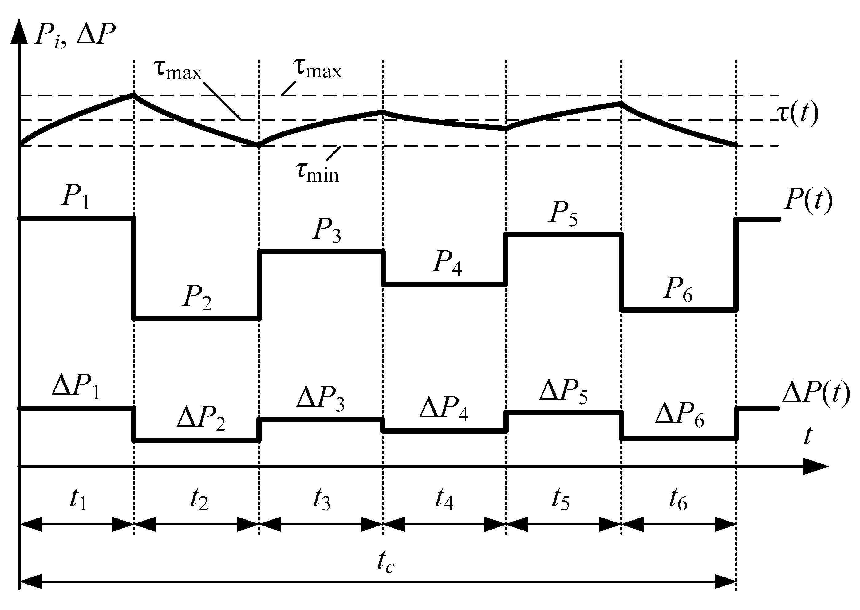
  • A single-mass heating model is used, which allows for obtaining the simplest analytical dependencies between the power losses and the motor temperature since, in this case, the temperature change on each section of the load diagram is described by an exponential dependence with a single-time constant;
  • The linear temperature dependence of the insulation thermal aging rate (its thermal resource consumption rate) is assumed since only in this case will the average temperature value determine the average insulation aging rate.
In practice, although less accurate, more convenient methods of equivalent values are often used. The method of average losses and methods of equivalent current, torque, and power, derived from the first one, are discussed in detail in Section 4.1 hereof.
The method of average losses allows for evaluating the motor’s thermal regime by the average temperature excess. Therefore, this method entails certain inaccuracies since motor overheating on individual work cycle intervals may exceed not only the average excess but also the permissible excess. If the motor operates in an overheating mode longer than the allowable time on this interval, it may burn out despite being properly chosen based on average losses. Thus, when using this method, it is necessary to check that the time tmax on the maximum load section is less than the motor’s heating constant tmax < Theat. If this condition is not met, the method of average losses is unacceptable. Consequently, when analyzing new modes, it is advisable to derive equivalent load parameters and motor temperature as continuous plots. This approach is implemented in the proposed technique for assessing the thermal state, as discussed below in Section 6 and Section 7.

3. Problem Statement

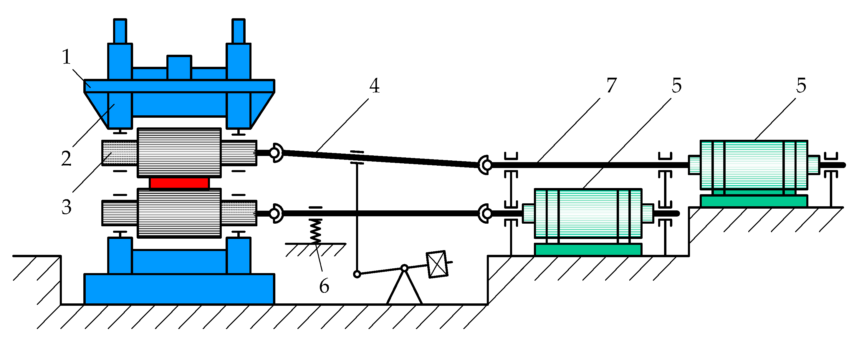
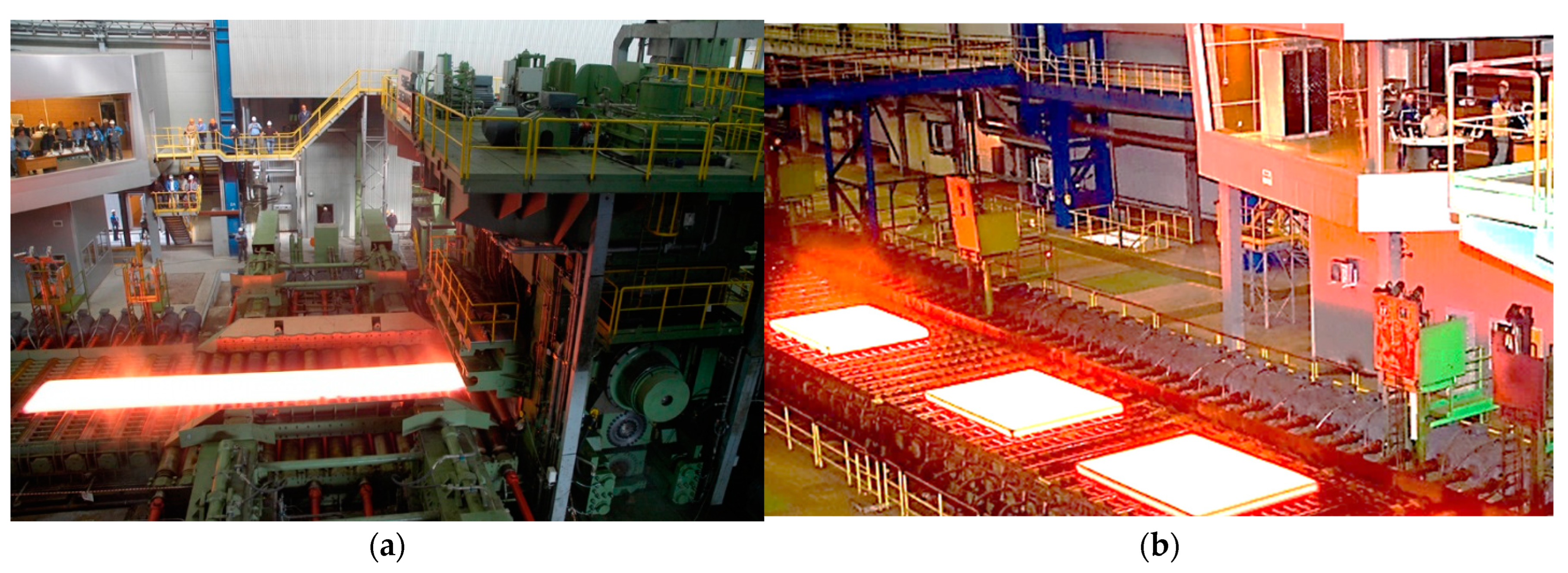
3.1. Specifics of the Research Object

In modern heavy plate mills, slab rolling is performed using two stands: a breakdown stand with two vertical rolls and a four-high horizontal stand with two working and two backup rolls. It is designed to draft the workpiece (half-product between the slab and the finished sheet) in several passes to meet profile requirements. Figure 2a shows a photo of the horizontal stand of the 5000 heavy plate mill. The mill can roll a batch of six workpieces (Figure 2b), with the sequential rolling of all slabs at the primary (roughing) stage. This stage may include up to six passes in a reversing mode. At the finishing stage, each slab is rolled individually (Figure 2a), and for thin sheets, this stage may include up to 19 passes.
The main drives of the upper and lower rolls of the horizontal stand are individual synchronous motors with rpm control. The VEM DMMYZ 3867-20V motors (VEM Sachsenwerk GmbH, Dresden, Germany) are used with a rated power of 12 MW each. High power indicates significant energy consumption during rolling, making the issues of rational load distribution and increasing drive efficiency relevant.
When the UMD and LMD motor speeds are not synchronized, the ski effect [41] (Figure 3a) occurs, where the front end of the workpiece may have an uncontrolled bend upwards (ski-up) or downwards (ski-down), as shown in Figure 3b. The ski effect arises due to vertical asymmetry of the deformation zone and, consequently, speed asymmetry of the metal under various process factors [42]. Downward bending is unacceptable since it causes the impact of a workpiece onto the conveyor rollers and the risk of getting stuck when exiting the stand. Herewith, controlled upward bending is desirable. It is achieved by initial speed mismatch (ski) in %, which reduces to zero as the front end of the workpiece is rolled. Uncontrolled front-end bending may lead to loss of product quality and gross damage to system components and, consequently, costly repairs and downtime. Some cases of severe accidents caused by unacceptable sheet bending are given in [41]. Refs. [43,44] discuss the issues of ski formation in more detail.
Figure 4 shows the structural diagram of the speed setting system of the mill 5000, implementing algorithms for ski formation after the biting and load leveling (distribution) in the steady rolling mode. The trajectory for each pass is formed by the second-level Automated Process Control System (APCS) model based on the mill’s productivity criteria and the required rolling temperature regime. The ramp generator in the scheme serves for emergency speed setting limitations. Its output is connected to the ski formation module, whose function is to ensure the specified radius and length of the curved section. The module regulates the upper roll drive speed setting according to the calculated speed mismatch reduction rate after biting. The speed difference required for ski formation causes a torque mismatch between the UMD and LMD motors. The load distribution controller (LDC) compensates for this mismatch. Its functions include eliminating speed differences after the ski formation and compensating for diameter setting deviations, roll wear, and other factors. When a mismatch of measured UMD torque and LMD torque signals occurs, the LDC output generates a control signal fed with different signs to the inputs of the speed control circuits of the MU and ML motors. The drive control system is discussed in more detail in [45].
As noted above, in heavy plate mill stands, the roll drives operate under unequal loads in steady rolling modes. Thereat, torques of the UMD and LMD motors can differ several times. Consequently, their equivalent loads (torques, currents, powers) also vary. This conclusion is confirmed by experimental studies.

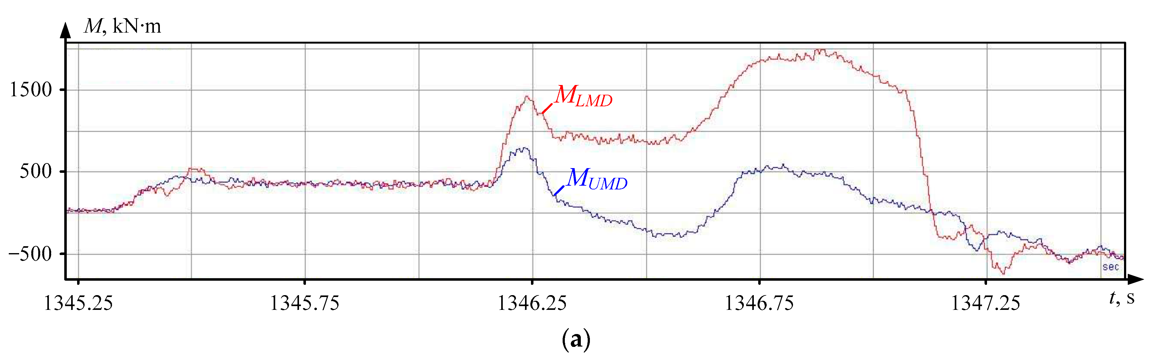
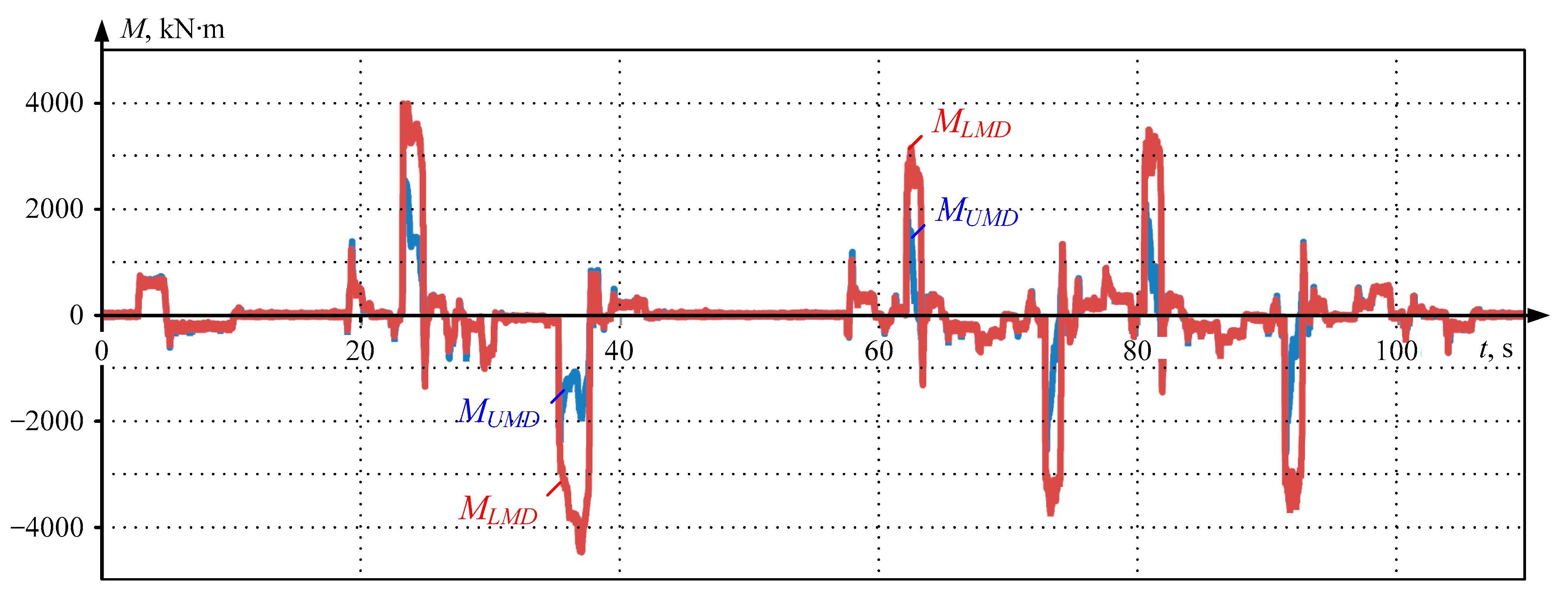
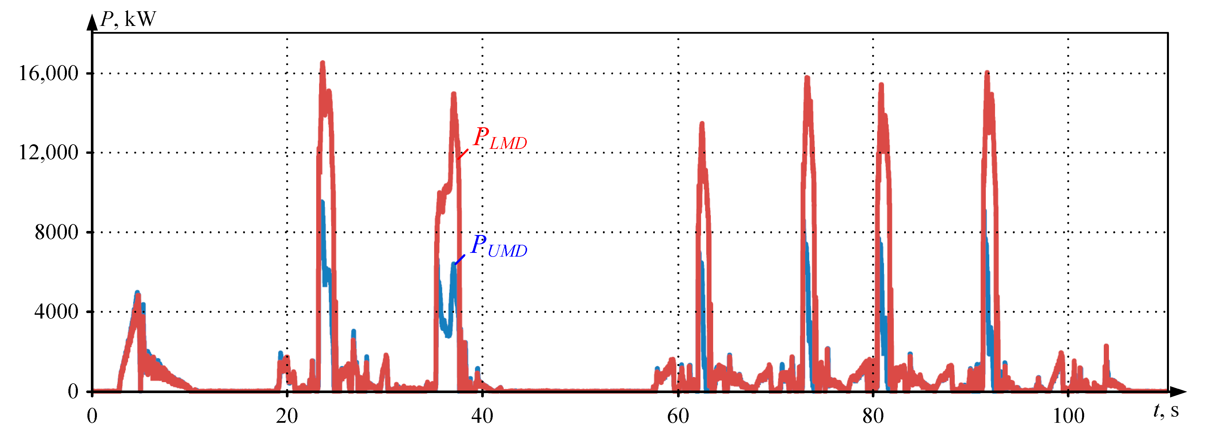
3.2. Analyzing Load Diagrams

Figure 5a shows oscillograms obtained over six passes of rough rolling for a batch of six slabs with the design ski formation and LDC settings. Figure 5b shows similar oscillograms for 19 passes of finish rolling of a single slab from the same batch. Windows 1, 4, and 5 display rolling forces, motor torques, and currents, respectively. The set and actual roll speeds (window 2) and similar drive speeds (window 3) are also shown. Windows 4 and 5 display the torque and current oscillograms for the UMD (MUMD, IUMD curves) and LMD (MLMD, ILMD curves) motors, which have identical patterns. Oscillograms in Figure 5a confirm that in each rough pass, the average load on the LMD motor ILMD(av) is almost three times the UMD motor load IUMD(av). Oscillograms in Figure 5b show the opposite: the UMD motor torques and currents IUMD(av) exceed those of the LMD motor ILMD(av) by two or more times. The loads approximately equalize only in the final passes of finish rolling.
As mentioned in the introduction, uneven distribution of rolling torques and corresponding currents disturbs the thermal regime of the more loaded motor, reduces insulation life and efficiency, and causes other negative consequences. Herewith, methods for calculating equivalent parameters known from drive theory do not consider motor load inequality [46,47]. Equivalent motor torques (currents, powers) are calculated using simplified (smoothed) diagrams, identical for UMD and LMD [48,49]. For example, Figure 6 shows speed and load diagrams for nine passes of finish rolling in the mill stand 5000. Similar diagrams, identical for UMD and LMD, built for the heaviest mode, are used to choose motors. Obviously, for drives operating under extreme loads, this simplification is unacceptable since it leads to inaccurate thermal state assessment. A calculation considering unequal load distribution and changes in each pass ratio is required.
Therefore, developing and experimentally verifying a technique for calculating the equivalent load of the upper and lower roll motors based on actual current or torque values for each pass is relevant. This calculation can be performed using pre-recorded data arrays or by processing data read in real time. The second approach is complex since the number of data points is unknown and varies for different passes. This results in large data arrays recorded at a certain interval (step). Below are examples illustrating calculations based on saved oscillograms of motor currents, torques, or powers for the reversing stand motors of the mill 5000. Data recording and storage are managed using the IbaPDA (Process Data Acquisition) system installed on the mill [50].
Alongside developing a technique for calculating equivalent loads, the problem of assessing the motor’s thermal state is set. This requires developing a temperature observer using a two-mass motor heating model that considers changes in the thermal state of the stator winding and stator iron. This simplification is acceptable since a detailed analysis of temperature distribution within the motor structure is not required.
The methodological approach being developed aims at defining equivalent loads and calculating UMD and LMD motor temperatures by actual rolling torques to be defined for each batch of sheets. In essence, this is a technique for assessing the constraints imposed by the drive on the process. This is necessary when implementing new or optimizing existing rolling programs. As noted, this problem is relevant when expanding the range of pipe blanks. These issues have not been covered in known literature sources.

4. Materials and Methods

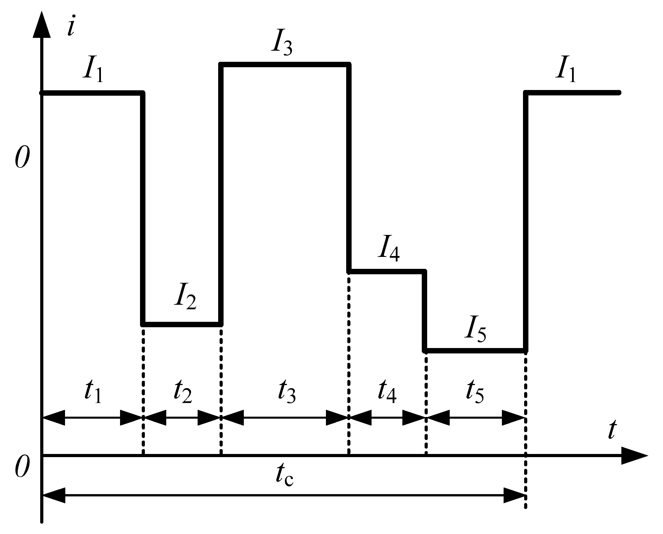
4.1. Methods for Calculating Equivalent Loads

Based on the load diagrams in Figure 6b, the drives of the reversing rolling mill stand can be classified as cyclic mechanisms characterized by motor operation modes S3, S5, and S6 [46,51].
According to established techniques, motor heating is checked based on the load diagram (Figure 7). The maximum temperature rise during the motor cycle τmax should not exceed the allowable value τacc, i.e., (τmax ≤ τacc) [52,53]. Thus, checking the motor power involves building a heating curve τ(t), which is labor-intensive and is not always possible. Therefore, in practice, simpler methods are used to check the motor’s thermal state. These include methods for calculating equivalent parameters: current, torque, and power based on the average loss method [47,54].
According to the average loss method, the motor temperature rise under constant heat transfer is determined by the average losses over the cycle:
Δ P ¯ = i = 1 m Δ P i t i / t c ,
where ΔPi is the loss power in the i-th interval; ti is the i-th interval duration; m is the number of intervals in the cycle; and tc is the cycle time.
When a motor current plot is available, the equivalent current method is used (the equivalent current is a constant one that causes the same losses in the motor as the actual current). Figure 8 shows an example of a current plot under long-term variable load.
The average power loss over the cycle is calculated according to (1) as follows:
Δ P ¯ = Δ P 1 t 1 + Δ P 2 t 2 + + Δ P n t n t 1 + t 2 + + t n .
Expressing power losses in each section through constant and variable components [55], we obtain the equivalent current:
I ¯ m = I 1 2 t 1 + I 2 2 t 2 + + I n 2 t n t 1 + t 2 + + t n = i = 1 n I i 2 t i t c .
In the general case of an arbitrary current plot:
I ¯ m = 1 t c 0 t ц i 2 t d t .
As defined, the equivalent current is compared with the rated motor current. If I ¯ m I n o m , the motor meets the thermal utilization requirements. It should be noted that the equivalent current method assumes independence of excitation, steel, and mechanical losses from the load (constancy). It also assumes the constancy of the rotor circuit resistance across all sections of the load plot.
With constant magnetic flux, when the motor torque M = c I , the equivalent torque method can be used to assess the motor load. For a staircase load plot, the equivalent torque is determined using a formula similar to (2):
M ¯ m = M 1 2 t 1 + M 2 2 t 2 + + M n 2 t n t 1 + t 2 + + t n = i = 1 n M i 2 t i t c .
When heat transfer varies, instead of tc in (4), the sum i = 1 n β i t i is used, where βi is the heat transfer deterioration factor in the i-th interval, corresponding to the angular speed in that interval. The linear dependence of the heat transfer deterioration factor on the angular speed ω is adopted [54]:
β = β 0 + 1 β 0 ω / ω n o m ,
where β0 is the heat transfer deterioration factor at zero rotor speed; ωnom is the rated angular speed.
The equivalent torque is then compared with the rated motor torque. If M ¯ m M n o m , the motor is fully utilized thermally. This method is applicable for both asynchronous and synchronous motors operating with rated magnetic flux, as well as DC motors with independent excitation.
When the drive and mechanism load diagram is determined by a motor power plot, it can be chosen and thermally verified using the equivalent power method but only at a proportional relationship between power and current, i.e., with constant losses in the stator iron, rotor resistance, magnetic flux, and rated angular speed:
Δ P C = const ,   R = const ,   Ф = const ,   ω = const = ω n o m .
Equivalent power for a staircase plot is calculated using a formula similar to (2) and (4). The resulting value is then compared to the motor’s rated power. This method can also be used for variable angular speed by converting the power at angular speed ωi to the equivalent power at rated speed ω = ω n o m using the relationship: P m i = P i ω n o m / ω i .
The formula for equivalent power with variable angular speed and heat transfer is the following:
P ¯ m = i = 1 n P i ω n o m / ω i 2 t i i = 1 n β i t i .
Also, regardless of the calculation method, the motor condition should be assessed for not only heating but also allowable maximum load:
I max I max .   a c c ; M max M max .   a c c ; P max P max .   a c c ,
where Imax, Mmax, and Pmax are the maximum current, torque, and power from the load diagrams of the motor I(t), M(t), and P(t), calculated considering dynamic processes such as start-up, braking, and reversing; Imax.acc, Mmax.acc, Pmax.acc are the maximum allowable current, torque, and power for the chosen motor, taken from reference data.
However, the dependencies (2) and (4) are valid for calculating equivalent loads only with a stepwise change in load, similar to Figure 8. In the general case, with an arbitrary plot shape, the effective torque and current of the motor are determined as average integral values over the considered period. To calculate them in the n-th interval, the following formulas are used:
M ¯ m = 1 t n 2 t n 1 t n 1 t n 2 M 2 ( τ ) d τ ,
I ¯ m = 1 t n 2 t n 1 t n 1 t n 2 I 2 ( τ ) d τ ,
where t n 1 and t n 2 are the start and end times of the interval.
The equivalent power is calculated as follows:
P ¯ m = 1 t n 2 t n 1 t n 1 t n 2 P ( τ ) d τ .
These equations are used to calculate equivalent loads based on online measurements for various rough and finish rolling passes in the mill stand 5000. Calculations were also performed for several passes without considering the motor field weakening. Preliminary arrays were digitized with a given step. As an example, the rolling of one slab is considered below; the ratios of equivalent parameters are analyzed for one and six passes.

4.2. Example Calculation Using Conventional Technique

To obtain information on the actual drive loads, the arrays obtained over the rolling cycle by direct measurements at the mill were digitized. Measurements were taken with a given step, the same for the oscillograms of UMD and LMD torques, chosen individually for each pass. The number of k points for different passes ranged from 70 to 203. Figure 9a and Figure 9b show, respectively, the UMD and LMD torque oscillograms for one rough rolling pass and their digitized curves. When digitizing torques, the considered interval of six rough rolling passes, as shown in Figure 5a, with pauses, is 220 s. The time step is constant Δτ = 0.002 s, so the number of points where torques are fixed is k = 110,000. Under these conditions, the dependencies in Figure 9b are absolutely identical to the original curves in Figure 9a, confirming the possibility of calculating equivalent loads based on the obtained arrays.
When calculating equivalent loads, it is assumed that the synchronous motor operates in a mode that minimizes energy losses [56]. In this mode, the reactive stator current component is not considered, so the motor torque is proportional to the active stator current component. The motor’s effective torque and current over the considered period are determined as average integral values. To calculate effective torque in the n-th interval, Formula (7) is used.
Figure 10 shows the upper and lower roll drive torques, obtained by digitization for six passes, and Table 1 provides the results of the calculation of equivalent torques M ¯ m _ U M D and M ¯ m _ L M D without and with considering the pause between two consecutive slab rollings (averaging over 110 s and 220 s, respectively). It can be seen that with an increase in the pause, the effective torques UMD and LMD decrease, but their ratio does not change. According to the datasheet, the rated motor torque Mnom = 1910 kN·m; thus, the torque reserve is quite sufficient.
Similar calculations were performed for the equivalent currents and powers of the UMD and LMD motors. A conclusion was made confirming that with the used drive coordinate control method, without entering the motor field weakening zone, there is a linear relationship between torques and currents, i.e., I ~ M by module.
The equivalent power of the motor for the considered case is defined as the average integral value, which can be approximately represented as the sum of powers over intervals:
P ¯ m = 1 t n 2 t n 1 t n 1 t n 2 P ( τ ) d τ 1 k 1 2 k 1 P i + P 1 2 + P k 2 .
Figure 11 shows the digitized UMD and LMD power plots, and Table 2 provides the processing results. It can be seen that, as in the cases with torques and currents, considering the pause, the effective UMD and LMD powers decrease, but their ratio does not change. As noted above, the rated motor power is Pnom = 12,000 kW.
The obtained ratios of equivalent torques, currents, and powers indicate that the equivalent load and, consequently, the amount of heat generated in the LMD motor, is are approximately twice as high as that generated in the UMD motor. Therefore, their calculation using the conventional technique with identical time diagrams of torques or powers will lead to a proportional error.
The analysis allows for making the following conclusions:
  • When calculating equivalent parameters in the rough rolling mode using the method with identical load diagrams for UMD and LMD, a two-fold error is obtained;
  • It is advisable to check the motors for heating by calculating effective torques or currents built based on real digitized time diagrams recorded for UMD and LMD during the rolling of a specific batch;
  • The thermal states of UMD and LMD motors should be compared based on determining the ratios of effective torques or currents over the same period of operation.
Similar conclusions were made when processing the data obtained at the stages of rough and finished rolling of a batch of five slabs, as shown in Figure 5. These conclusions formed the basis for developing the technique to calculate load modes and temperatures of the mill stand 5000 motors.

5. Implementation

Below is a technique for calculating equivalent loads that allows for automated testing of motor heating based on data obtained during rolling. It is applicable for processing data arrays recorded during measurements of the motor’s electrical parameters to determine its temperature.
The technique consists of the following steps:
  • Reading data arrays obtained from direct measurements with the IbaPDA system. If necessary, smoothing and averaging of data is performed using statistical processing algorithms;
  • Exporting data from the system to a Matlab file;
  • Calculating equivalent load parameters for a given time interval. The following intervals can be taken: one pass, all passes of rough or finish rolling a full cycle, or several cycles;
  • Averaging and comparing the results with the rated motor parameters.

5.1. Automatic Calculation of Equivalent Currents for the Rolling Cycle

Automatic calculation was performed using a model (observer) implemented in Matlab Simulink (ver. 8.3) (Figure 12). It was designed to calculate the time dependencies of equivalent current Im and/or torque Mm based on the initial dependencies i(t) and m(t), represented as Ii and Mi values at fixed time instants, imported from the IbaPDA system.
Figure 13 shows the results of calculating the root mean square values of torque using the proposed algorithm for the finish rolling of one slab. Window 1 shows the oscillograms of UMD and LMD torques. The profile should be classified as heavy since the motor torques reach the limit of 4600 kN·m in most passes. Window 2 shows the calculated dependencies of the equivalent torques of these motors. At the end of the cycle (at the time instant t = 200 s), the following results were obtained: equivalent torque M m _ U M D ( t = 200   s ) = 1600 kN·m and equivalent torque M m _ L M D ( t = 200   s ) = 1100 kN·m. Thus, in the analyzed finish rolling mode, the UMD motor was loaded 1.45 times more than the LMD motor.
The following conclusions were drawn based on equivalent load calculations of UMD and LMD motors:
  • During the rolling of a heavy stock batch, the upper roll motor is more loaded (and, obviously, heats up more) than the lower one. However, this conclusion is valid only for the considered case where the motor temperatures before rolling match the ambient temperature, corresponding to complete motor cooling. Section 6 will discuss motor heating during the rolling of several batches of the same stock;
  • The ratio of equivalent currents is similar: during rolling, I ¯ m _ U M D increases by 1.5 times (from 650 to 980 A).
Thus, the upper roll motor heats up more than the lower roll motor during the rolling cycle of a batch. This conclusion is further confirmed by the results of restoring motor temperatures. Initially, a two-mass thermal model based on differential equations of the stator winding temperature (first mass) and stator iron temperature (second mass) was considered.

5.2. Structure of Object-Oriented Thermal State Observer

The diagram in Figure 14a shows the structure of the object-oriented thermal state observer of the rolling mill stand motors. It conditionally displays the UMD and LMD drives as Drive 1 and Drive 2 structures exchanging data with thermal models implemented in a Programmable Logic Controller (PLC). The one-way data exchange (from the object to the virtual model) confirms that this structure represents a digital shadow of the motors’ thermal state. Any model implementable in Matlab Simulink (ver. 8.3), e.g., four-mass or seven-mass models from the Simscape Thermal library, can be used as a thermal model.
When developing an observer, a virtual commissioning technique was used, which was applied for modernizing coilers of a wide-band hot rolling mill [57], as well as in developing an elastic moment observer regarding the electromechanical system of a mill stand 5000 [58]. The method is based on simulating processes on a model followed by object correction. It involves building a simulation model in Matlab-Simulink or Simscape and transferring it to PLC. Data exchange with the object involves exporting data from the PDA signal archiving system. During the virtual commissioning of the observer, the PLC connects to the physical object, management algorithms are tuned, and parameter settings are refined.
According to the stated objectives, in the investigated case, the thermal state of the UMD and LMD motors should be compared without a detailed analysis of the temperature of the motor’s individual parts. It is known that the “motor temperature” term generally refers to the stator temperature. Therefore, at the initial stage, a two-mass Thermal model was used, the structure of which is shown in Figure 14b. According to the definition given in [59], a two-mass thermal model refers to a motor where the first and second nodes are, respectively, the stator winding and the rest or fragment of the machine. It allows for obtaining the time dependencies of the stator temperature, calculated as the sum of the winding and iron temperatures, considering thermal losses. The calculation methodology and an example of using the two-mass model to calculate the thermal modes of an asynchronous motor were considered in [60,61]. The principle of building the model is also valid for the investigated salient-pole synchronous motor.
The thermal model, considering the winding and stator iron mass heating, has been built based on differential equations characterizing the heat exchange between the winding and the stator iron by the cooling airflow [62]. The equations used consider the following:
1. Power dissipated in the stator winding:
P E M = R A i A 2 + R B i B 2 + R C i C 2 ,
where R A , R B , and   R C are phase resistances, and i A , i B , and i C are phase currents;
2. Power spent on air cooling:
P c o o l 1 = ( T 1 T a i r ) A a i r 1 ,
P c o o l 2 = ( T 2 T a i r ) A a i r 2 ,
where T a i r is the cooling air temperature, and A a i r 1 and A a i r 2 are the coefficients of heat transfer from the corresponding masses to the cooling air;
3. Power P e x , associated with friction losses, losses transmitted from the machine surface to the environment, etc.
The differential equations of the two-mass thermal model were obtained considering the heat capacities of the stator winding mass C 1 and the stator iron mass C 2 :
C 1 d T 1 d t = P E M + P 12 + P c o o l 1 ,
C 2 d T 2 d t = P 21 + P c o o l 2 + P e x ,
where T 1 and T 2 are the stator winding and iron temperatures.
At equal resistances RPH and currents IPH of each phase, the power P E M is expressed through the effective phase current value IPH:
P E M = 3 R P H I P H 2 .
Thermal powers at direct and reverse heat exchange (from the stator winding to the iron and back) are the following:
P 12 = T 1 T 2 A 12 ,
P 21 = T 2 T 1 A 12 ,
where A 12 is the heat transfer coefficient.
Based on the expressions presented, a model structure was compiled in Matlab-Simulink. It allowed for the obtaining of time dependences of a motor temperature, calculated as the sum of a winding temperature of T1 and an iron temperature of T2, which was calculated with the account heat losses incurred. The input signal was an array of data obtained as a result of direct measurements by the IbaPDA system. These data were exported to a Matlab file, then processed, and the motor’s equivalent load parameters were calculated. The model parameters are given in Table 3.
The proposed algorithm is applicable for calculating the temperature based on online measurement results for a fixed time instant, e.g., after rolling a batch of 10 slabs over 19 passes (this example is considered below). Initially, its implementation is shown to assess the thermal state of UMD and LMD motors based on data recorded during rolling. This approach allows for an accurate assessment of the thermal state after rolling any number of slabs or batches.

6. Results

6.1. Restoring Equivalent Currents and Motor Temperatures

Below are the results of calculating the motors’ equivalent currents and temperatures at various values of initial speed mismatch between the upper and lower rolls, i.e., with different “ski” settings, %. Calculations were performed using digital arrays of UMD and LMD motor currents. The thermal model in Figure 14b was used. Figure 15 shows the calculation results for two options for finish rolling:
  • Rolling with a large “ski” (10%) with slow load leveling (Figure 15a);
  • Rolling with a small “ski” (1.5%) with effective load distribution regulator operation (Figure 15b).
The following conclusions are made from the comparison of oscillograms:
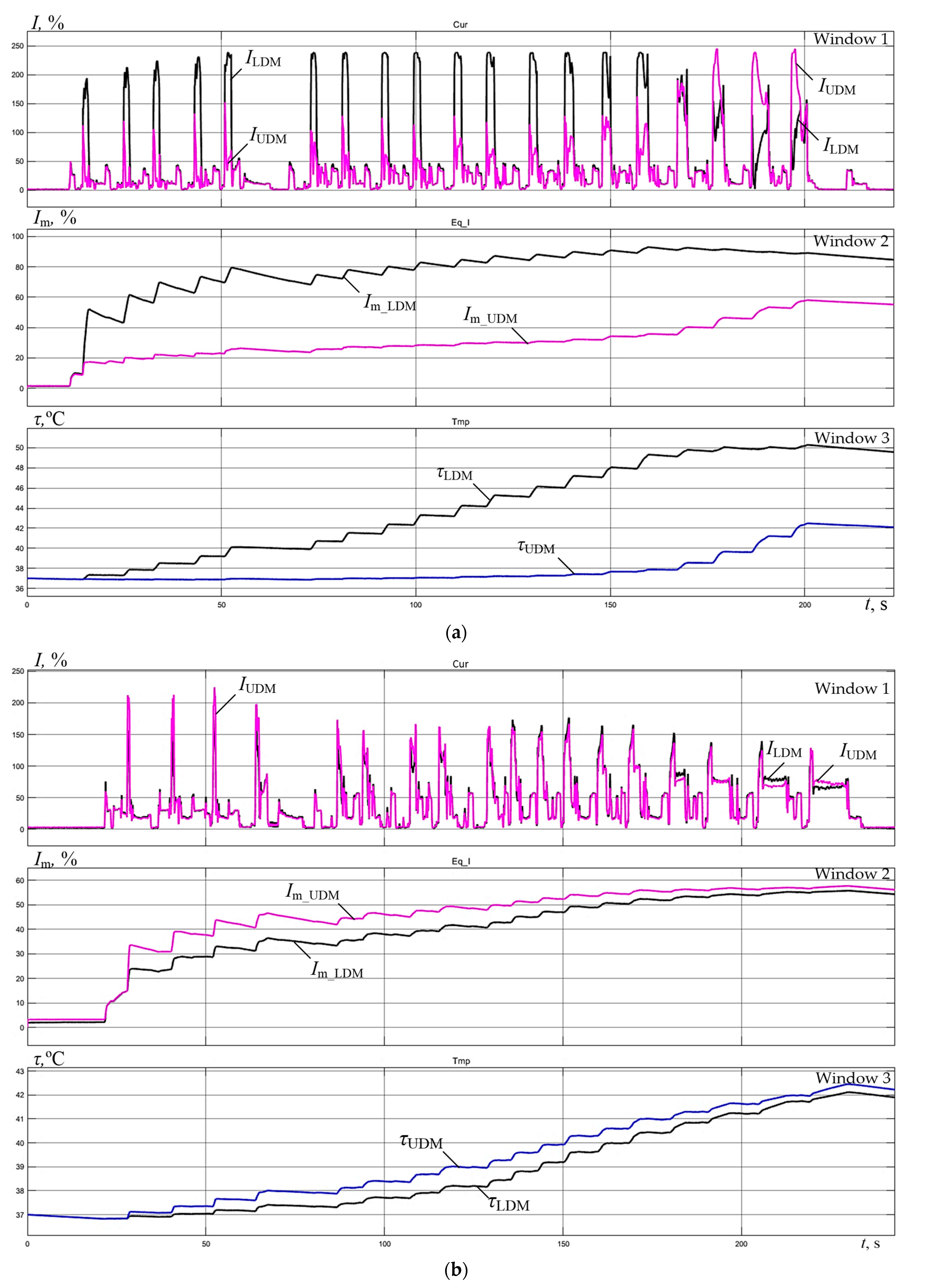
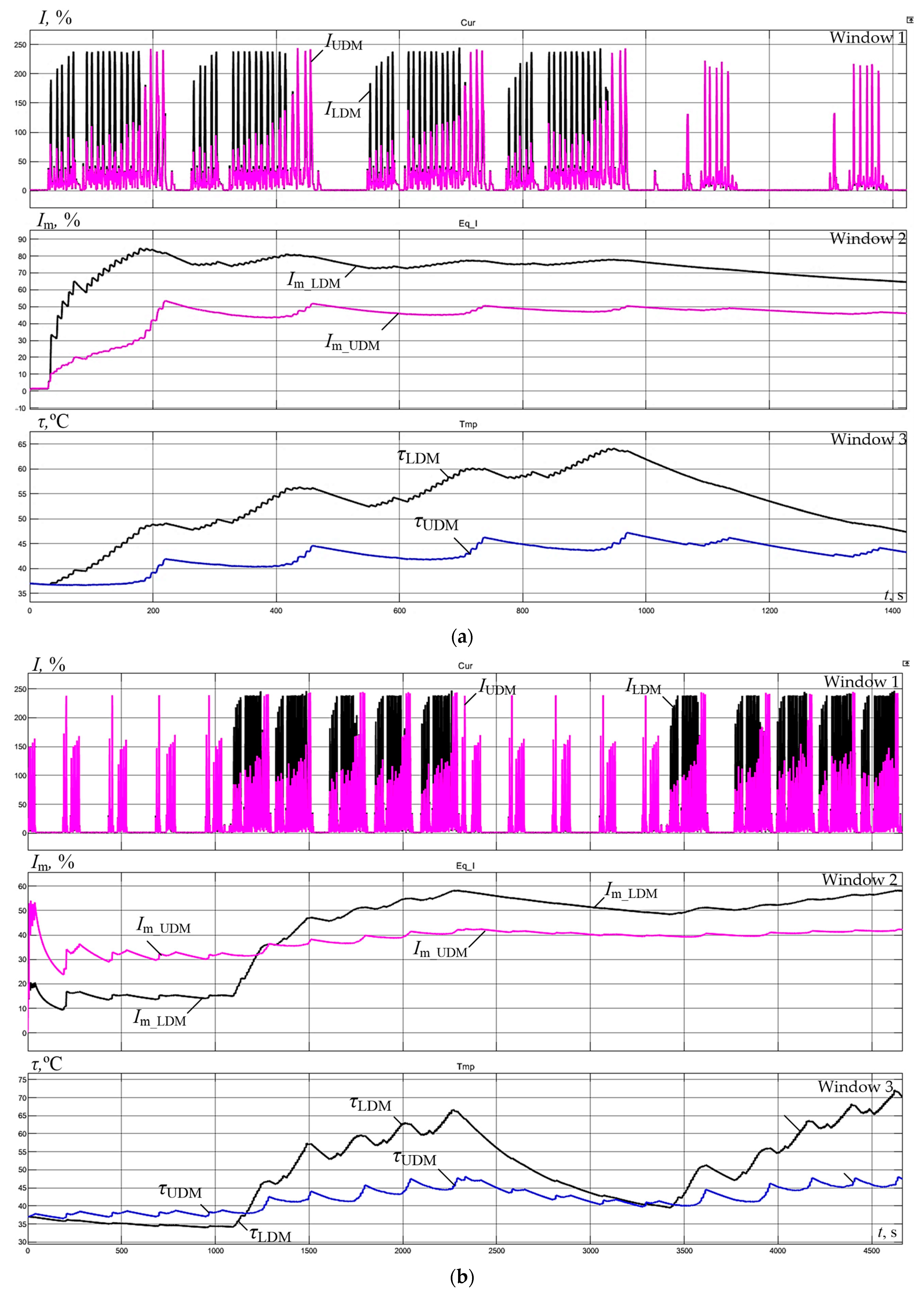
  • With a large “ski” setting (Figure 15a), in all passes except the last four, the LMD current (window 1) exceeds the UMD current. Therefore, at the end of rolling, the equivalent current I ¯ m _ L M D is higher and equal to 85% of the rated value, while the I ¯ m _ U M D current is 55% of the rated value. Similar currents with a “ski” of 1.5% in Figure 15b at the end of rolling are virtually identical and equal to 55%. The alignment of equivalent currents in the second case indirectly confirms that the thermal regime of the LMD motor improves. Since the equivalent currents of the motors are significantly below the rated value (below 100%), we can assert that overheating does not occur in either case. This is confirmed by the temperature plots in window 3;
  • The dependencies in window 3 show that during the finish rolling, the temperature plots reach steady-state values. Thereat, the difference in steady-state values in Figure 15a is 16% (50 °C for LMD and 42 °C for UMD). The steady-state temperature in Figure 15b is the same for both motors and is approximately 42 °C;
The analysis of temperature change plots allows for asserting that the thermal modes of the motors are satisfactory in both cases. The temperature is significantly below the permissible limit, so for the analyzed product range, continuous temperature control is not required.
3.
Speed mismatch during rolling significantly affects motor heating. With a large “ski” (Figure 15a), the LMD and UMD motor temperatures at the end of the rolling cycle differ by 16% or 1.2 times. This confirms the advisability of load leveling across passes to improve thermal modes. Along with improving the thermal balance of the motors, this will improve their efficiency [63,64] (this is explained below in Section 6.2).
The verification of the reliability of the temperature restoration by a developed observer was implemented onto the roll motors of a two-stand reversing tandem cold rolling mill. This developed algorithm for temperature restoration was implemented at this mill. The choice of unit is due to the availability of built-in temperature sensors on motors, which makes it possible to compare the results obtained with real temperatures. The results of the adequacy assessment confirmed the conclusion of satisfactory accuracy. The discrepancy between values reconstructed and measured does not exceed 5%.
To confirm the direct dependence of temperature on speed mismatch, Figure 16 shows plots similar to those considered, obtained for two phases of finish rolling of a heavy profile with more intensive loading of the motors per pass. They were obtained by means of completely equalizing loads across their passages (window 1). This is ensured with zero speed mismatch (zero “ski”) and high performance of a load distribution controller. The oscillograms of motor individual speeds for upper and lower rolls are not represented in this figure (nor in the previous figures applied). When a “ski” setting is zero, these speeds coincide, which was confirmed by studies previously performed [15]. As can be seen, the equivalent currents of UMD and LMD (window 2) and the motor temperatures (window 3) completely coincide. A pause between the rolling phases leads to a slight temperature decrease of about 2 °C or 4%. In other respects, the conclusions made based on Figure 15 are also valid for these plots.
The analysis allows for justifying an important way to improve the thermal modes of individual drive motors of rolling mill stands. Temperature equality is ensured by leveling their loads and improving the “ski” formation algorithms and the LDC response. In this direction, a load synchronization system for the plate mill stand [65] and an adaptive load distribution regulator [66] have been developed. Computer modeling and experiments ensured their industrial implementation at the mill 5000.

6.2. Experimental Assessment of Electricity Losses

The experimental studies of algorithms for matching the loads on UMD and LMD motors have led to the conclusion that the energy performance of electric drives has been improved. This was achieved by increasing the efficiency of a variable-frequency electric drive as a result of a more uniform distribution of motor current loads. These experiments compared the following:
-
Rolling with equalizing speeds and loads due to the adoption of adaptive LDC;
-
Rolling with a “ski” set, equal to 7% of a rolling speed established.
When analyzing identical passes, an increase in the average efficiency per pass of 0.965 to 0.968 was confirmed. It was proved that the total power losses within electric drives for the options compared are the following:
-
With loads balancing—0.633 MW;
-
With a “ski” of 7%—0.752 MW.
Due to this, an average power reduction was achieved because of a speed matching of 0.119 MW. This amounts to 18.9% power losses when rolling under the same motor load (a power per pass of 0.633 MW) or 15.8% power losses when rolling under a specified “ski” (a power per pass of 0.752 MW). This reduction in electricity consumption per pass is 1 MJ or 3.7%. The difference in energy consumption per rolling cycle lasting 180 s, including 16 passes, is 5330 kJ (1.48 kW∙h) or 5.7%. This confirms significant technical and economic effects due to energy savings.
The specified reduction in electricity consumption is the maximum possible one. It is achieved under the condition of complete coordination of motor torques in the absence of a “ski”. It is obvious that rolling with an ideal match of speeds and torques regarding UMD and LMD motors is rarely performed in practice. Herewith, it may be argued that adopting adaptive LDC provides less mismatch of speeds and a reduction in the time of their operation under different loads. This is confirmed by the results of the long-term operation of the algorithms implemented.

7. Discussion of Results

Undoubtedly, process pauses occurring during rolling, including those associated with the cooling of workpieces on the roller table during thermomechanical rolling, positively affect the thermal modes of the motors. This is confirmed by the oscillograms in Figure 17. Compared with previous cases, they were obtained over longer periods. Figure 17a shows the finishing phase of one batch and then the start of the new roughing phase of the next batch. Figure 17b shows the rolling of two batches of 10 slabs over 1 h and 10 min. As can be seen, by the end of the finishing phase, i.e., the end of rolling one batch, the motor temperatures almost reach a steady state. After the process pauses in the roughing phase of the second batch (Figure 17a,b), they decrease. Therefore, its assessment for the rolling of several batches will not provide additional information but require processing larger data arrays. Calculation for one rolling cycle is quite sufficient, and the conclusion on the satisfactory thermal modes of the motors remains valid. This conclusion is important when checking motor heating during the rolling of new workpiece sizes.
The aforementioned conclusion that in the roughing phase, the UMD motor heats more than the LMD one is valid only for the first batch (interval 0–1200 s in Figure 17b) when the motors have equal initial temperatures. The oscillograms in window 3 show that during the roughing stage, the motor temperature almost decreases to the initial value. As rolling continues without long pauses, the LMD motor temperature exceeds or equals the UMD motor temperature. Therefore, the aforementioned conclusions are correct.
In the given examples, the results of previously performed measurements were processed. However, this approach can be applied to calculations based on online measurements. For this purpose, the algorithm and the Matlab software package can be used, which ensure calculations and data processing, including the smoothing of measured industrial data. In this case, the thermal model (Figure 14) should receive instantaneous current values, and the structure itself will perform the functions of a thermal state observer for the motors.
The procedures for implementing the method proposed to monitor the thermal state of engines are identical both when processing pre-recorded data and within the online mode. They are implemented in PLC according to the structure represented in Figure 14a, using a thermal model (Figure 14b). The text of this article provides a demonstration of the method proposed for processing data as previously recorded during a rolling process. When processing data recorded online, presenting the method in the form of text with pictures becomes difficult.
The operation of an algorithm implemented to monitor the thermal state of mill stand motors 5000 confirmed their operability and the possibility of its implementation online. However, it should be noted that changing the engine temperature is a fairly lengthy process. Therefore, we recommend assessing engine heating after rolling a single batch or several ones within the same product range. This is convenient when mastering new rolled profiles when the continuous assessment of temperature changes is not required. At the same time, online monitoring is necessary while improving rolling speed conditions when dynamic processes have a significant impact on the heating of engines.
Thus, a technique for assessing the restrictions imposed by the drive on the process has been developed. It is based on an algorithm for calculating the equivalent loads and temperatures of the individual drive motors of the reversing stand using current (torque) measurements per pass recorded directly during rolling.
The methodology developed may be applied to assess the thermal state of electric motors not only within thick-sheet rolling mills but also in motors of continuous production lines, whose electric drives are connected through the metal being processed. These include continuous groups of wide-band hot rolling mills [7,9], continuous web processing lines [67], section mills for wire production [68] and some other units applied. An additional condition that must be met by interconnected electric drives of such lines is to provide constant tension within their inter-stand spaces under steady-state and dynamic modes [67].
This article examined an observer of a thermal state of rolling mill stand motors. In accordance with the rationale provided for in Section 1, it is a facility-oriented digital shadow as a hard- and software device which monitors continuously the state of a specific industrial facility by monitoring coordinates determining this state. This definition corresponds to the structure represented in Figure 14a. With its assistance, monitoring (continuous monitoring) of an equivalent load and temperature of a facility can be performed.
As it is known, the difference between DS and DT is the unidirectional flow of information from a physical facility to a digital one, while within DTs, bidirectional data exchange is performed [69,70]. In accordance with the objectives stated, DTs were not considered here; however, an observer developed may be transformed into a DT structure. Such a need may arise when developing a comprehensive system for monitoring the condition of a rolling mill electromechanical system. For a 5000 mill, a similar development is mentioned in [71] to justify building a cyber-physical system for centralized monitoring of a mechatronic system’s status (it is stated that such a task has been posed for the first time). The centralized cyber-physical system shall provide online monitoring of a motor condition with the prospect of the automated correction of speed and load modes depending on their temperature. In this case, a digital shadow developed will be transformed into a digital twin of a facility’s thermal state.
It should be considered that the issue of improving energy performance, briefly discussed in a previous section, is complex and may be the subject of a separate publication. A much more detailed study shall evaluate the reduction in energy costs for rolling achieved by improving the load conditions of electric drives. Herewith, changes in losses caused not only by an increase in efficiency but also losses caused by regulating motor parameters, in particular, two-zone speed control (rolling with the weakening of a motor field), should be taken into account. Also, it is necessary to evaluate energy-saving resources by optimizing the speed and load conditions of motors along their passes.
It is obvious that rolling production is the most important component of the metallurgical industry, providing a wide range of final products from metallurgical plants. Along with electric arc melting of metal, rolling is the most energy-intensive production process. Thus, reducing energy losses even by a fraction of a percent may significantly increase production energy efficiency in absolute terms. In this regard, considering completed developments from the perspective of energy saving is an urgent task that deserves independent research. The results of such studies and surveys are planned to be represented in further publications.

8. Conclusions

  • The implementation of the IIoT concept in industrial enterprises should be carried out through the introduction of modern online monitoring technologies based on observers (digital shadows) of the coordinates of electromechanical and mechatronic systems. The concept of an object-oriented observer (object-oriented digital shadow) has been introduced. This is a hardware and software device that continuously monitors the state of a specific industrial facility by tracking the coordinates that determine its state;
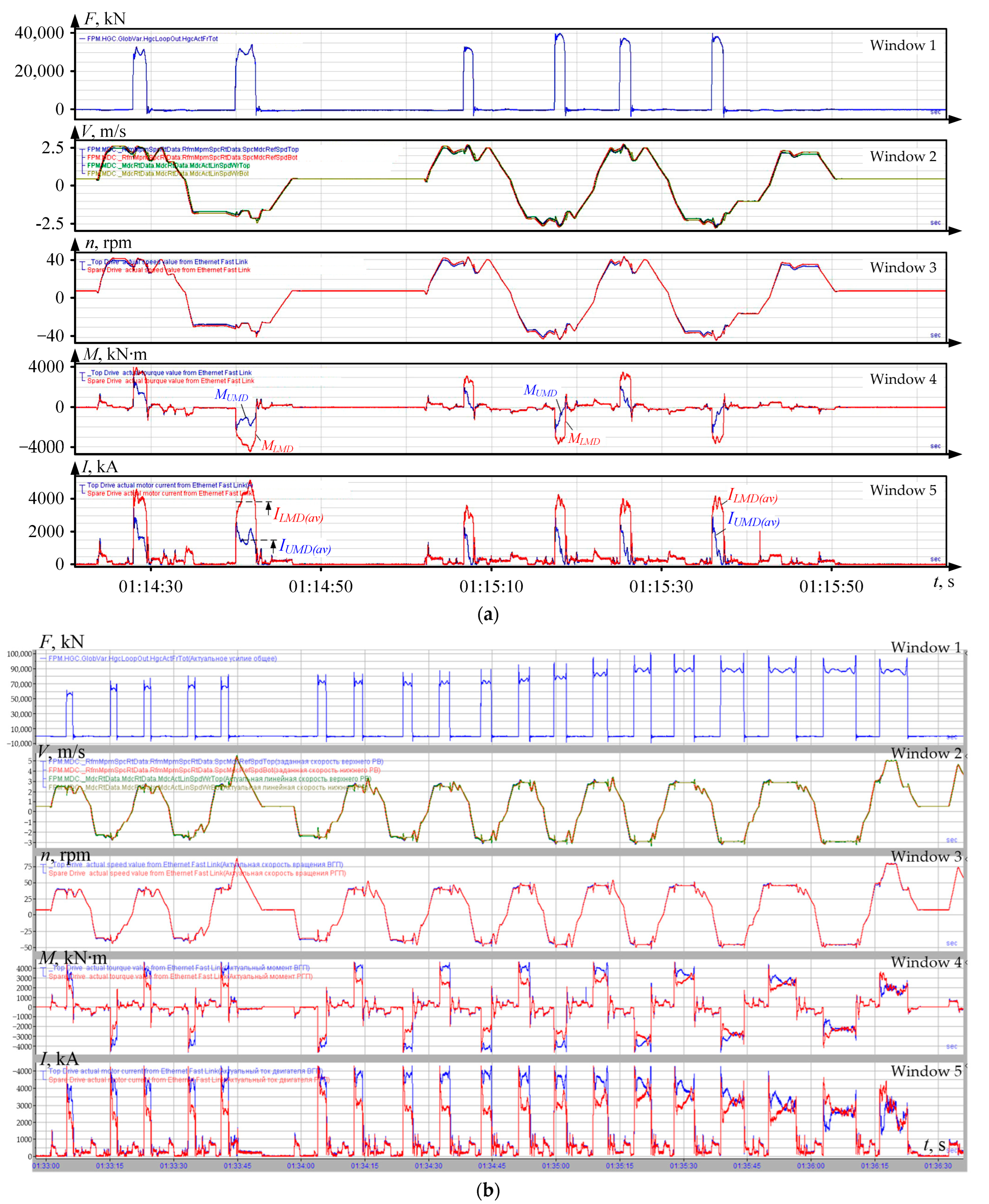
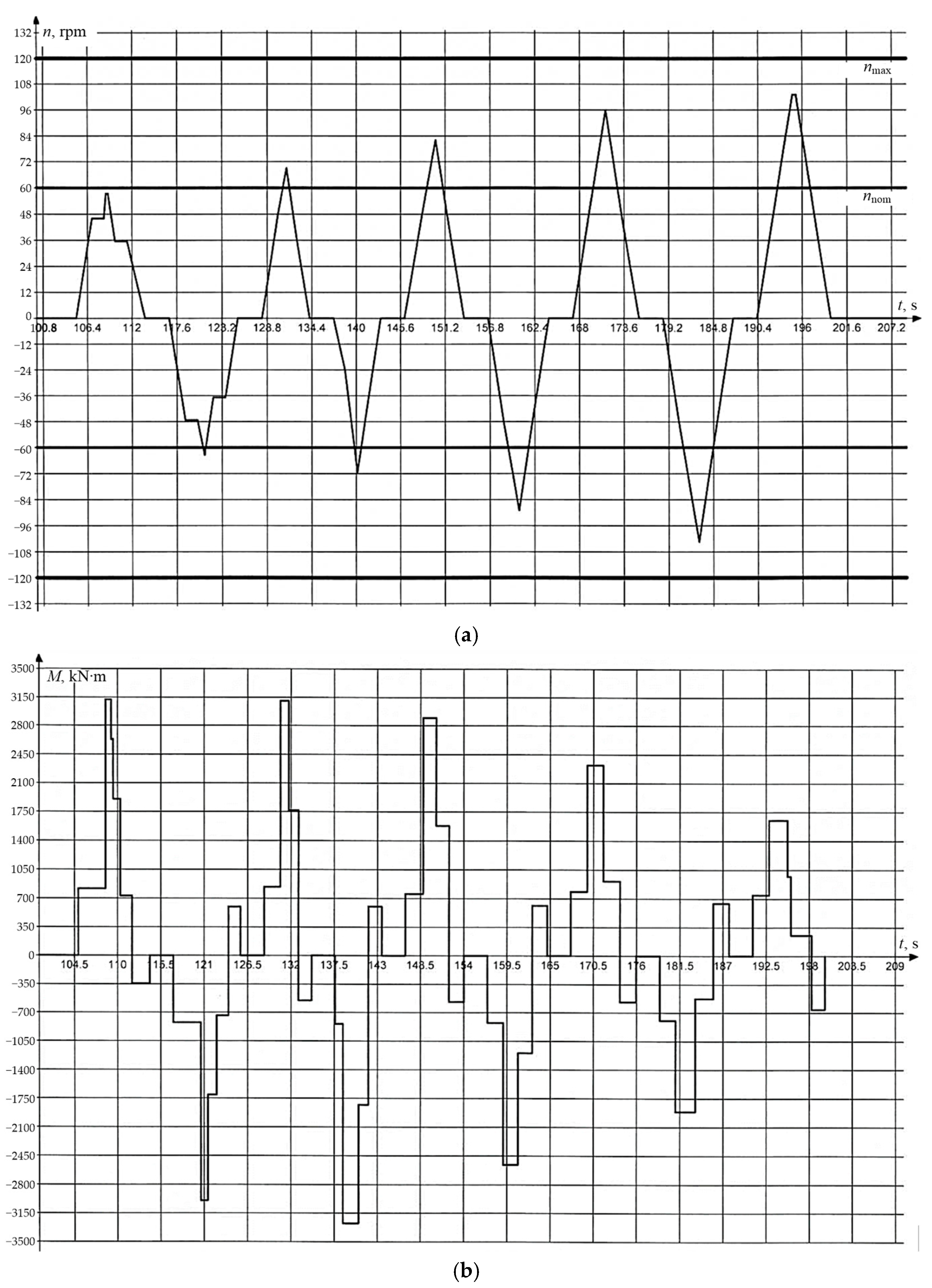
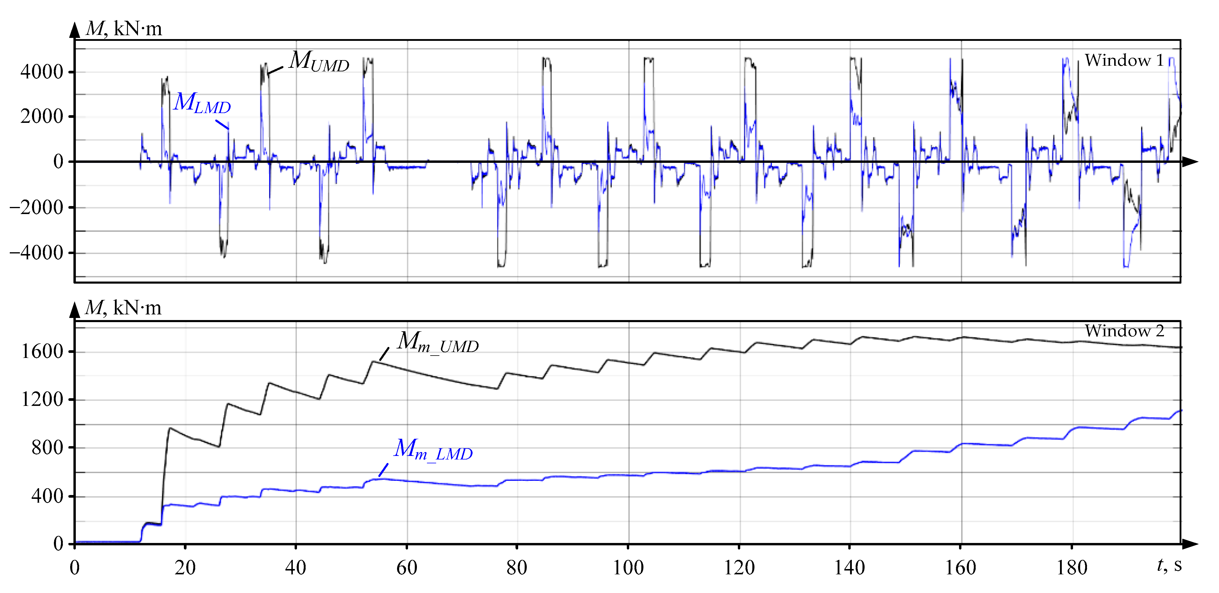
  • Experimental studies of the operating modes of the mill 5000 horizontal stand drives showed a significant difference in the UMD and LMD motor loads. At the roughing stage, the average LMD torque and current are greater than those of the UMD; in the finishing stage, their ratio is reversed. With the existing speed control system settings, load leveling occurs only in the last passes. This leads to disproportionate load distribution, different motor heating, and the need to control their temperature during rolling;
  • It was shown that known methods for analyzing motor load and thermal modes are based on calculations using smoothed load diagrams identical to UMD and LMD, leading to inaccurate thermal state assessments. The relevance of developing a technique for online motor temperature monitoring by processing arrays of currents or torques recorded during rolling has been justified;
  • A technique for calculating equivalent loads was developed, allowing automated motor heating checks based on data obtained during rolling. It comprises the following steps:
    • Reading data arrays created as a result of direct measurements by the IbaPDA system;
    • Exporting data to a Matlab-Simulink file;
    • Calculating equivalent load parameters over a given time interval (one pass, all roughing or finishing passes, full cycle, etc.);
    • Comparing the results with the motor’s rated parameters.
The procedure for comparing the calculated load parameters with the rated parameters of the motors is generally accepted when analyzing the load conditions of electric drives. It allows one to conclude whether the motor is heating up or not when performing a particular rolling program. In the presented study, it was mentioned in Section 4.1 when describing known methods for calculating equivalent load parameters, which are equivalent current, equivalent torque, and equivalent power. Specific results of such a comparison are given in conclusions 1 and 2 based on the analysis of the oscillograms in Figure 15.
5.
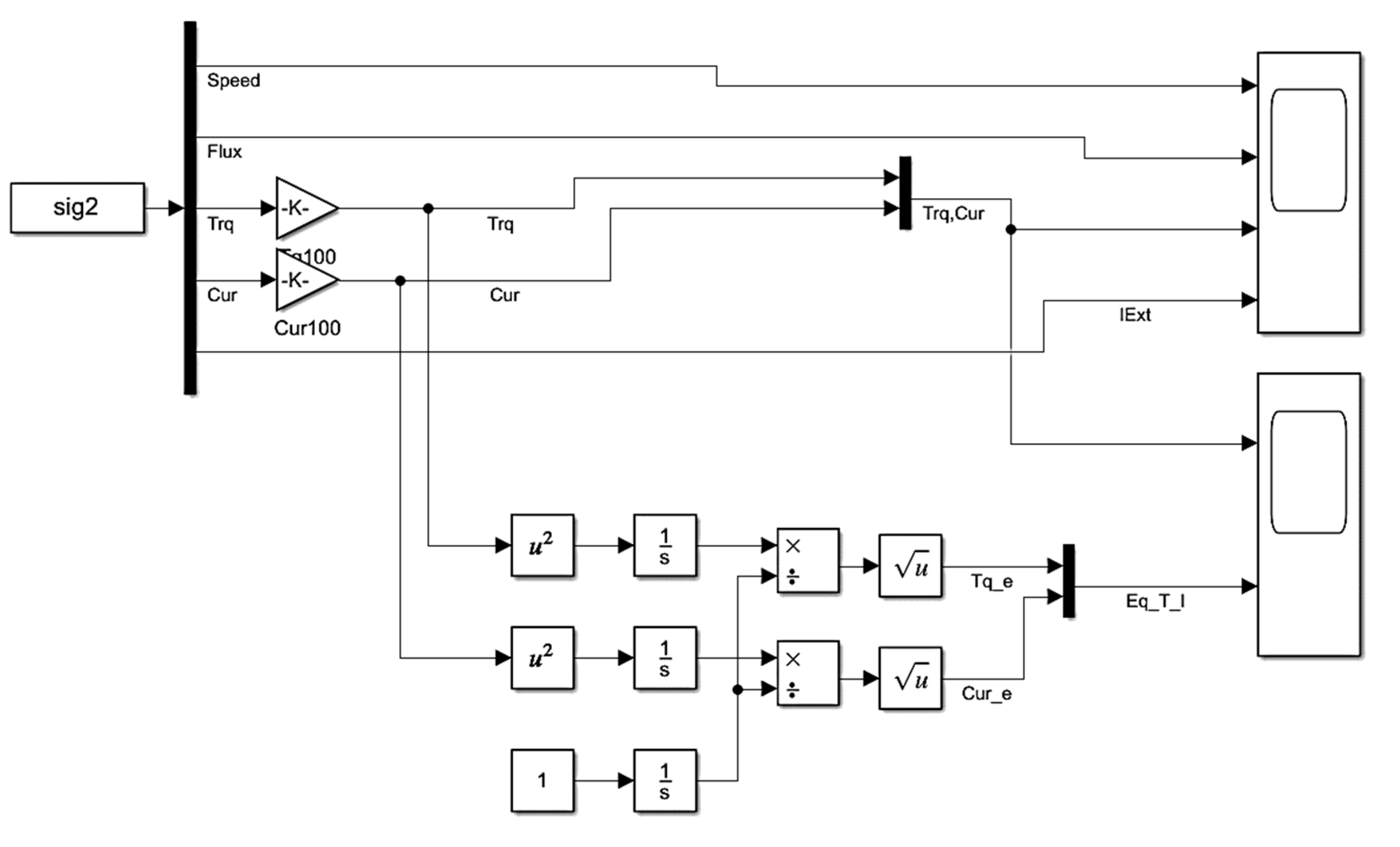
Based on the proposed technique’s algorithm, an object-oriented root mean square torque and current observer and the thermal state observer for rolling stand motors were developed. The thermal state observer uses the motor thermal model scheme and models to calculate heat exchange in Matlab-Simulink based on parameters from IbaPDA;
6.
The thermal modes of motors in the finishing passes during rolling with different “skies” were studied. It is confirmed that leveling the equivalent currents ensures temperature equality. It is found that regardless of speed mismatches, the equivalent currents of UMD and LMD motors are significantly below the rated values, so no motor overheating occurs when rolling the analyzed product range;
7.
The developed technique is a tool for determining the constraints the drive imposes on the rolling program in an automated mode. This allows for optimizing speed and load modes, which is relevant when mastering new rolling products.
The obtained results represent theoretical development and practical implementation of the concept of object-oriented digital shadows for monitoring the condition of operating equipment.

Author Contributions

Conceptualization, A.A.R. and A.S.K.; methodology, S.S.V. and A.A.R.; software, I.N.E. and S.S.V.; validation, B.M.L.; formal analysis, V.R.K.; writing—original draft preparation, S.S.V. and A.S.K.; writing—review and editing, V.R.K.; visualization, I.N.E.; supervision, A.A.R. and B.M.L. All authors have read and agreed to the published version of the manuscript.

Funding

This work was financially supported by the Moscow Polytechnic University within the frame-work of the grant named after Pyotr Kapitsa.

Data Availability Statement

Data are contained within the article.

Conflicts of Interest

The authors declare no conflicts of interest.

References

  1. Li, Q.; Yang, Y.; Jiang, P. Remote Monitoring and Maintenance for Equipment and Production Lines on Industrial Internet: A Literature Review. Machines 2023, 11, 12. [Google Scholar] [CrossRef]
  2. Errandonea, I.; Beltrán, S.; Arrizabalaga, S. Digital Twin for maintenance: A literature review. Comput. Ind. 2020, 123, 103316. [Google Scholar] [CrossRef]
  3. Attaran, M.; Attaran, S.; Celik, B.G. The impact of digital twins on the evolution of intelligent manufacturing and Industry 4.0. Adv. Comput. Intell. 2023, 3, 11. [Google Scholar] [CrossRef]
  4. Brecher, C.; Dalibor, M.; Rumpe, B.; Schilling, K.; Wortmann, A. An Ecosystem for Digital Shadows in Manufacturing. Procedia CIRP 2021, 104, 833–838. [Google Scholar] [CrossRef]
  5. Radionov, A.A.; Bovshik, P.A.; Loginov, B.M.; Karandaev, A.S.; Khramshin, V.R. Construction Principle for Object-Oriented Digital Twins of Mechatronic Complexes of Rolling Mills. In Proceedings of the 2023 International Russian Smart Industry Conference (SmartIndustryCon), Sochi, Russia, 27–31 March 2023; pp. 516–522. [Google Scholar] [CrossRef]
  6. Eleftheriou, O.T.; Christos-Nikolaos, E. Anagnostopoulos. Digital twins: A brief overview of applications, challenges and enabling technologies in the last decade. Digit. Twin 2022, 2, 2. [Google Scholar] [CrossRef]
  7. Hu, X.L.; Zhang, Q.S.; Zhong, Z.H.; Yong, T.I.; Liu, X.H.; Wang, G.D. Application of Approximation Full-Load Distribution Method to Pass Scheduling on Plate Mill With Hydro-Bending System. J. Iron Steel Res. Int. 2006, 13, 22–26. [Google Scholar] [CrossRef]
  8. Kun, E.; Szemmelveisz, T. Energy efficiency enhancement in the Hot Rolling Mill. Mater. Sci. Eng. 2014, 3, 43–50. [Google Scholar]
  9. Orcajo, G.A.; Rodríguez, J.; Ardura, P.; Cano, J.M.; Norniella, J.G.; Llera, R.; Cifrián, D. Dynamic estimation of electrical demand in hot rolling mills. In Proceedings of the 2015 IEEE Industry Applications Society Annual Meeting, Addison, TX, USA, 18–22 October 2015; pp. 1–9. [Google Scholar] [CrossRef]
  10. Lagerev, A.V. Loading of Lifting and Transport Equipment; BSTU: Bryansk, Russia, 2010; p. 180. [Google Scholar] [CrossRef]
  11. Ali, A.H.; Kazmi, S.M.H.; Poonja, H.A.; Khan, H.; Shirazi, M.A.; Uddin, R. Motor Parametric Calculations for Robot Locomotion. Eng. Proc. 2022, 20, 8. [Google Scholar] [CrossRef]
  12. Philipp, M.; Schwenzfeier, W.; Fischer, F.D.; Wödlinger, R.; Fischer, C. Front end bending in plate rolling influenced by circumferential speed mismatch and geometry. J. Mater. Process. Technol. 2007, 184, 224–232. [Google Scholar] [CrossRef]
  13. Lee, K.; Han, J.; Park, J.; Kim, B.; Ko, D. Prediction and control of front-end curvature in hot finish rolling process. Adv. Mech. Eng. 2015, 7. [Google Scholar] [CrossRef]
  14. Wang, Y.; Zhao, L.; Cui, X.; Zhu, X. Research on numerical simulation and process parameters of three-roll bending based on thickness characteristics of extra-thick plate. Adv. Mech. Eng. 2019, 11. [Google Scholar] [CrossRef]
  15. Karandaev, A.S.; Zinchenko, M.A.; Semitko, A.Y.; Evdokimov, S.A.; Petukhova, O.I. Technological Causes of Vertical Workpiece Asymmetry in Plate Rolling Mills. In Lecture Notes in Mechanical Engineering, Proceedings of the 8th International Conference on Industrial Engineering, ICIE 2022, Sochi, Russia, 16–20 May 2022; Radionov, A.A., Gasiyarov, V.R., Eds.; Springer: Cham, Switzerland, 2023. [Google Scholar] [CrossRef]
  16. Tang, J. Motor Sizing Basics Part 3: How to Calculate Speed, Acceleration Torque, and RMS Torque. Available online: https://blog.orientalmotor.com/motor-sizing-basics-part-3-acceleration-torque-and-rms-torque (accessed on 22 May 2024).
  17. Semenova, M.N.; Yakushev, I.A.; Zagolilo, S.A.; Kharitonov, Y.; Shevchuk, V.A.; Ivshin, I.V. Calculation and Construction of Load Diagrams and Static Characteristics of Multi-Motor Electric Drive System Using Methods of Equivalent Forces and Reduced Moments. E3S Web Conf. 2020, 220, 01033. [Google Scholar] [CrossRef]
  18. Saheba, R.; Rotea, M.; Wasynczuk, O.; Pekarek, S.; Jordan, B. Virtual Thermal Sensing for Electric Machines. IEEE Control Syst. Mag. 2010, 30, 42–56. [Google Scholar]
  19. Stephen Ejiofor, O.; Justin, U.; Damian Benneth, N.; Uche, O. Development and thermal modeling of an induction machine. Int. J. Eng. Technol. 2019, 8, 500–508. [Google Scholar] [CrossRef]
  20. Beguenane, R.; Benbouzid, M.E.H. Induction motors thermal monitoring by means of rotor resistance identification. IEEE Trans. Energy Convers. 1999, 14, 566–570. [Google Scholar] [CrossRef]
  21. Wallscheid, O. Thermal Monitoring of Electric Motors: State-of-the-Art Review and Future Challenges. IEEE Open J. Ind. Appl. 2021, 2, 204–223. [Google Scholar] [CrossRef]
  22. Ma, T.; Komatsu, T.; Wang, B.; Wang, Y.; Lin, C. Observer Designs for Simultaneous Temperature and Loss Estimation for Electric Motors: A Comparative Study. In Proceedings of the IECON 2019-45th Annual Conference of the IEEE Industrial Electronics Society, Lisbon, Portugal, 14–17 October 2019; pp. 1234–1241. [Google Scholar] [CrossRef]
  23. Nestler, H.; Sattler, P.K. On-line-estimation of temperatures in electrical machines by an observer. Electr. Mach. Power Syst. 1993, 21, 39–50. [Google Scholar] [CrossRef]
  24. Bagheripoor, M.; Bisadi, H. An investigation on the roll force and torque fluctuations during hot strip rolling process. Prod. Manuf. Res. 2014, 2, 128–141. [Google Scholar] [CrossRef]
  25. Yang, Z.; Liu, D.; Zhang, X.; Huang, W.; Zheng, G. Optimization of Rolling Schedule for Single-Stand Reversible Cold Rolling Mill Based on Multiobjective Artificial Fish Swarm Algorithm. Wirel. Commun. Mob. Comput. 2022, 2022, 9167017. [Google Scholar] [CrossRef]
  26. Jia, C.; Shan, X.; Niu, Z. High Precision Prediction of Rolling Force Based on Fuzzy and Nerve Method for Cold Tandem Mill. J. Iron Steel Res. Int. 2008, 15, 23–27. [Google Scholar] [CrossRef]
  27. Zhou, F.-Q.; Cao, J.; Zhang, J.; Yin, X.; Jia, S.-H.; Zeng, W. Prediction model of rolling force for tandem cold rolling mill based on neural networks and mathematical models. J. Cent. South Univ. (Sci. Technol.) 2006, 37, 1155–1160. [Google Scholar]
  28. Lian, W.; Du, F. Reliability Prediction of Near-Isothermal Rolling of TiAl Alloy Based on Five Neural Network Models. Materials 2023, 16, 6709. [Google Scholar] [CrossRef] [PubMed]
  29. Specht, A.; Bocker, J. Observer for the rotor temperature of IPMSM. In Proceedings of the 14th International Power Electronics and Motion Control Conference EPE-PEMC 2010, Ohrid, Macedonia, 6–8 September 2010. [Google Scholar] [CrossRef]
  30. Specht, A.; Wallscheid, O.; Bocker, J. Determination of rotor temperature for an interior permanent magnet synchronous machine using a precise flux observer. In Proceedings of the 2014 International Power Electronics Conference (IPEC-Hiroshima 2014—ECCE ASIA), Hiroshima, Japan, 18–21 May 2014; pp. 1501–1507. [Google Scholar] [CrossRef]
  31. Milanfar, P.; Lang, J.H. Monitoring the thermal condition of permanent-magnet synchronous motors. IEEE Trans. Aerosp. Electron. Syst. 1996, 32, 1421–1429. [Google Scholar] [CrossRef]
  32. Gundabattini, E.; Mystkowski, A.; Idzkowski, A.; Singh R, R.; Solomon, D.G. Thermal Mapping of a High-Speed Electric Motor Used for Traction Applications and Analysis of Various Cooling Methods—A Review. Energies 2021, 14, 1472. [Google Scholar] [CrossRef]
  33. Meng, T.; Zhang, P. A Review of Thermal Monitoring Techniques for Radial Permanent Magnet Machines. Machines 2022, 10, 18. [Google Scholar] [CrossRef]
  34. Zhu, Y.; Xiao, M.; Lu, K.; Wu, Z.; Tao, B. A Simplified Thermal Model and Online Temperature Estimation Method of Permanent Magnet Synchronous Motors. Appl. Sci. 2019, 9, 3158. [Google Scholar] [CrossRef]
  35. Sonnaillon, M.O.; Bisheimer, G.; De Angelo, C.; García, G.O. Online Sensorless Induction Motor Temperature Monitoring. IEEE Trans. Energy Convers. 2010, 25, 273–280. [Google Scholar] [CrossRef]
  36. Foti, S.; Testa, A.; De Caro, S.; Scelba, G.; Scarcella, G. Sensorless Rotor and Stator Temperature Estimation in Induction Motor Drives. In Proceedings of the 2020 ELEKTRO, Taormina, Italy, 25–28 May 2020; pp. 1–6. [Google Scholar] [CrossRef]
  37. Czerwinski, D.; Gęca, J.; Kolano, K. Machine Learning for Sensorless Temperature Estimation of a BLDC Motor. Sensors 2021, 21, 4655. [Google Scholar] [CrossRef]
  38. Gao, Z.; Habetler, T.G.; Harley, R.G.; Colby, R.S. A Sensorless Rotor Temperature Estimator for Induction Machines Based on Current Harmonic Spectral Estimation Scheme. In Proceedings of the 2006 12th International Power Electronics and Motion Control Conference, Portoroz, Slovenia, 30 August–1 September 2006; pp. 431–437. [Google Scholar] [CrossRef]
  39. Sarapulov, F.N.; Goman, V.; Trekin, G.E. Temperature calculation for linear induction motor in transport application with multiphysics approach. IOP Conf. Ser. Mater. Sci. Eng. 2020, 966, 012105. [Google Scholar] [CrossRef]
  40. Zyuzev, A.M.; Metelkov, V.P. Allowance for the Influence of Temperature Fluctuations on the Induction Motor Stator Winding Thermal Resource. Russ. Internet J. Electr. Eng. 2015, 2, 62–71. [Google Scholar]
  41. Anders, D.; Münker, T.; Artel, J.; Weinberg, K. A dimensional analysis of front-end bending in plate rolling applications. J. Mater. Process. Technol. 2012, 212, 1387–1398. [Google Scholar] [CrossRef]
  42. Varshavsky, E.A.; Khrapov, M.A.; Basurov, V.M. System of Automated Control of the Workpiece’s Front End Bending in the Roughing Stand with Individual Roll Drive. In Proceedings of the XI Congress of Millers, Magnitogorsk, Russia, 9–11 October 2017; pp. 57–62. [Google Scholar]
  43. Kiefer, T.; Kugi, A. An analytical approach for modelling asymmetrical hot rolling of heavy plate. Math. Comput. Model. Dyn. Syst. 2008, 14, 249–267. [Google Scholar] [CrossRef]
  44. Chikishev, D.N.; Pozhidaeva, E.B. Analysis of the causes of vertical bending of the strip front end at hot rolling on the basis of mathematical modeling. Izvestia VUZov. Chernaya Metall. = Izv. Ferr. Metall. 2016, 59, 204–208. [Google Scholar] [CrossRef]
  45. Gasiyarov, V.R.; Radionov, A.A.; Loginov, B.M.; Zinchenko, M.A.; Gasiyarova, O.A.; Karandaev, A.S.; Khramshin, V.R. Method for Defining Parameters of Electromechanical System Model as Part of Digital Twin of Rolling Mill. J. Manuf. Mater. Process. 2023, 7, 183. [Google Scholar] [CrossRef]
  46. Klyuchev, V.I. Electric Drive Theory: Textbook for Universities; Energoatomizdat: Moscow, Russia, 2001; p. 760. [Google Scholar]
  47. Shreiner, R.T. Electromechanical and Thermal Modes of Asynchronous Motors in Frequency Control Systems: Textbook; Academy of Vocational Education: Ekaterinburg, Russia, 2008; p. 360. [Google Scholar]
  48. Shishko, V.B.; Trusov, V.A.; Chichenev, N.A. Fundamentals of Technology of Rolling on Reversing Mills: Textbook; MISIS: Moscow, Russia, 2007; p. 92. [Google Scholar]
  49. Tomashevsky, N.I.; Tomashevsky, D.N.; Emelyanov, A.A.; Ippolitov, V.V. Development of Electric Drives of Production Mechanisms. Guidance Manual; RSVPU: Ekaterinburg, Russia, 2006; p. 229. [Google Scholar]
  50. ibaPDA Scalable Basic Software for Measured Data Collection. Available online: https://www.iba-ag.com/ru/ibapda (accessed on 7 October 2023). (In Russian).
  51. Kuvshinov, A.A.; Grekov, E.L. Electric Drive Theory: Lecture Notes: In 2 Part; IPK GOU OSU: Orenburg, Russia, 2009; p. 197. [Google Scholar]
  52. Temperature Rise and Life of an AC Motor. Available online: https://www.orientalmotor.com/ac-motors-gear-motors/technology/temperature-rise-and-life-of-an-ac-motor.html (accessed on 22 May 2024).
  53. Zyuzev, A.M.; Metelkov, V.P. Thermodynamic Models for Thermal Testing of Asynchronous Motors. Electr. Eng. 2012, 9, 48–52. [Google Scholar]
  54. Chilikin, M.G.; Sandler, A.S. General Course of Electric Drive; Energoizdat: Moscow, Russia, 1981; p. 576. [Google Scholar]
  55. Sivyakova, G.; Orlov, S.Y.; Wójcik, W.; Komada, P. Development of simulation model of electric drive of decoiler. Prz. Elektrotech. 2014, 90, 173–176. [Google Scholar] [CrossRef]
  56. Shreiner, R.T.; Polyakov, V.N.; Medvedev, A.V. Electromechanical Resource of an RMP-Controlled Synchronous Drive in Intermittent Operating Modes. ESC 2014, 3, 9–13. [Google Scholar]
  57. Gasiyarov, V.R.; Bovshik, P.A.; Loginov, B.M.; Karandaev, A.S.; Khramshin, V.R.; Radionov, A.A. Substantiating and Implementing Concept of Digital Twins for Virtual Commissioning of Industrial Mechatronic Complexes Exemplified by Rolling Mill Coilers. Machines 2023, 11, 276. [Google Scholar] [CrossRef]
  58. Gasiyarov, V.R.; Radionov, A.A.; Loginov, B.M.; Karandaev, A.S.; Gasiyarova, O.A.; Khramshin, V.R. Development and Practical Implementation of Digital Observer for Elastic Torque of Rolling Mill Electromechanical System. J. Manuf. Mater. Process. 2023, 7, 41. [Google Scholar] [CrossRef]
  59. Metelkov, V.P. About Calculation of Parameters of Two-Mass Thermodynamic Model of Induction Motor. Bulletin of the South Ural State University. Ser. Power Eng. 2016, 16, 58–65. [Google Scholar]
  60. Anuchin, A.S.; Fedorova, K.G. A two-mass thermal model of the induction motor. Russ. Electr. Eng. 2014, 85, 83–86. [Google Scholar] [CrossRef]
  61. Anuchin, A.S.; Fedorova, K.G. Using a Two-Mass Thermal Model to Choose an Asynchronous Motor. Vestn. ISPEU 2013, 3, 1–3. [Google Scholar]
  62. Chenchevoi, V.; Romashykhin, I.; Romashykhina, Z.; Al-Mashakbeh, A.S. Analysis of the special features of the thermal process in an induction generator at high saturation of the magnetic system. Electr. Eng. Electromech. 2017, 3, 16–18. [Google Scholar] [CrossRef]
  63. Specification Guideelectric Motors. Available online: https://static.weg.net/medias/downloadcenter/ha0/h5f/WEG-motors-specification-of-electric-motors-50039409-brochure-english-web.pdf (accessed on 22 May 2024).
  64. Shabanov, V.A.; Khakimov, E.F.; Kalimgulov, A.R.; Sergeenkova, E.V. Studying the Fependence of the Motor and Frequency Converter Efficiency on the Load Factor and Rotation Speed. Electr. Data Process. Facil. Syst. 2019, 4, 83–90. [Google Scholar]
  65. Karandayev, A.S.; Loginov, B.M.; Zinchenko, M.A.; Mazitov, D.M.; Podolko, A.S. Speed Coordination System for Electric Drives of a Plate Mill Stand: Theory and Development. In Proceedings of the 2021 International Ural Conference on Electrical Power Engineering (UralCon), Magnitogorsk, Russia, 24–26 September 2021; pp. 566–571. [Google Scholar] [CrossRef]
  66. Gasiyarov, V.R.; Kornilov, G.P.; Loginov, B.M.; Zinchenko, M.A.; Khramshin, R.R.; Odintsov, K.E. Adaptive Load Division Controller for Electric Drives of Roll Stand. In Proceedings of the 2023 International Conference on Industrial Engineering, Applications and Manufacturing (ICIEAM), Sochi, Russia, 15–19 May 2023; pp. 1135–1140. [Google Scholar] [CrossRef]
  67. Magura, D.; Fedák, V.; Kyslan, K. Modeling and Analysis of Multi-motor Drive Properties in a Web Processing Continuous Line. Procedia Eng. 2014, 96, 281–288. [Google Scholar] [CrossRef]
  68. Radionov, A.A.; Petukhova, O.I.; Erdakov, I.N.; Karandaev, A.S.; Loginov, B.M.; Khramshin, V.R. Developing an Automated System to Control the Rolled Product Section for aWire Rod Mill with Multi-Roll Passes. J. Manuf. Mater. Process. 2022, 6, 88. [Google Scholar] [CrossRef]
  69. Fuller, A.; Fan, Z.; Day, C.; Barlow, C. Digital Twin: Enabling Technologies, Challenges and Open Research. IEEE Access 2020, 8, 108952–108971. [Google Scholar] [CrossRef]
  70. Kritzinger, W.; Karner, M.; Traar, G.; Henjes, J.; Sihn, W. Digital Twin in manufacturing: A categorical literature review and classification. IFAC-PapersOnLine 2018, 11, 1016–1022. [Google Scholar] [CrossRef]
  71. Voronin, S.S.; Loginov, B.M.; Gasiyarova, O.A.; Evdokimov, S.A.; Karandaev, A.S.; Khramshin, V.R. Telemetry System to Monitor Elastic Torque on Rolling Stand Spindles. J. Manuf. Mater. Process. 2024, 8, 85. [Google Scholar] [CrossRef]
Figure 1. Working line scheme for the rolling mill’s main drive with independent roll drives: 1—roll stand; 2—housing; 3—working rolls; 4—universal spindles; 5—motors; 6—spindle balance; 7—countershaft.
Energies 17 03878 g001
Figure 2. View of the rolling stand of the mill 5000 from the operator’s station (a) and sequential rolling of a batch of six slabs (b).
Energies 17 03878 g002
Figure 3. Workpiece bending when moving on the conveyor (a) and bending directions at the stand exit (b).
Energies 17 03878 g003
Figure 4. Block diagram of the drive control system implementing the functions of emerging upward bend and load distribution: Sref(t) and Vref(t)—motion trajectory and speed, set as points; V(t)—drive speed setting generated by the interpolator.
Energies 17 03878 g004
Figure 5. Load distribution of UMD and LMD motors during 6 passes of rough rolling (a) and 19 passes of finish rolling (b).
Energies 17 03878 g005
Figure 6. Simplified speed (a) and load (b) diagrams for 9 passes of reversing rolling.
Energies 17 03878 g006
Figure 7. Staircase plots for motor shaft power Pi, losses ΔPi, and temperature τ under variable load.
Energies 17 03878 g007
Figure 8. Motor current Plot i = f t under long-term variable load.
Energies 17 03878 g008
Figure 9. Motor torque oscillograms for one pass (a) and their digitized curves (b).
Energies 17 03878 g009aEnergies 17 03878 g009b
Figure 10. Digitized motor torques UMD and LMD during rough rolling of one slab over six passes.
Energies 17 03878 g010
Figure 11. Digitized power plots of UMD and LMD motors during rough rolling of one slab over six passes.
Energies 17 03878 g011
Figure 12. Structure of the observer for calculating the root mean square torque and current by processing imported data.
Energies 17 03878 g012
Figure 13. Measured and equivalent torques of UMD and LMD motors during the finish rolling of one slab.
Energies 17 03878 g013
Figure 14. Structure of object-oriented thermal state observer of rolling mill stand motors (a) and block diagram of motor thermal model (b).
Energies 17 03878 g014
Figure 15. Equivalent current and temperature calculation results for 10% (a) and 1.5% (b) “Ski” settings: window 1—effective current values; window 2—RMS current values; window 3—motor temperatures; current units—% of rated values.
Energies 17 03878 g015
Figure 16. Equivalent current and temperature plots for finish rolling of two slabs.
Energies 17 03878 g016
Figure 17. Dependencies similar to those in Figure 15 over long time intervals (calculation results for 10% (a) and 1.5% (b) “Ski” settings).
Energies 17 03878 g017
Table 1. Equivalent UMD and LMD torques during rough rolling.
ParameterAveraging
from 0 to 110 s
Averaging
from 0 to 220 s
UMD   Motor   Torque   M ¯ m _ U M D , kN·m448.7317.6
LMD   Motor   Torque   M ¯ m _ L M D , kN·m965.6683.0
Sum   M ¯ m _ U M D + M ¯ m _ L M D , kN·m1414.01000.6
Table 2. Equivalent UMD and LMD powers during rough rolling of a slab, kW.
ParameterAveraging
from 0 to 220 s
Averaging
from 0 to 110 s
UMD Motor Power P ¯ m _ U M D , kW183.4359.0
LMD Rated Motor Power P ¯ m _ l M D , kW346.9684.9
Sum P ¯ m _ U M D + P ¯ m _ l M D , kW 530.31044.0
Table 3. Parameters of the two-mass thermal model of the main drive motor (Figure 14b).
Parameter DesignationValueUnit of Measure
Stator iron mass m 2 70,000kg
Stator winding mass m 1 5000kg
Stator winding heat capacity C 1 385J/(kg·K)
Stator iron heat capacity C 2 447J/(kg·K)
Stator winding-to-iron contact area A 3 m 2
Stator winding to iron heat transfer coefficient K 1 200W/(m·K)
Insulation thickness between the winding and the stator iron D0.0044m
Stator heat removal coefficient K 2 1500 W / ( m 2 · K )
Electrical resistance of the stator winding R 0 stator0.07Ohm
Temperature coefficient of winding resistance α 0.0043 1 K
Disclaimer/Publisher’s Note: The statements, opinions and data contained in all publications are solely those of the individual author(s) and contributor(s) and not of MDPI and/or the editor(s). MDPI and/or the editor(s) disclaim responsibility for any injury to people or property resulting from any ideas, methods, instructions or products referred to in the content.

