Article

Study on the Influencing Factors of Electrical Characteristics of Articulated Split-Zone Insulator Arc

by
Like Pan
1,
Biaohuan Xie
2,
Liming Chen
1,*,
Tong Xing
1,
Haibo Zhang
1,
Yanming Lu
2 and
Yang Song
2
1
China Academy of Railway Sciences Corporation Limited, Beijing 100081, China
2
School of Electrical Engineering, Southwest Jiaotong University, Chengdu 611756, China
*
Author to whom correspondence should be addressed.
Energies 2024, 17(16), 3883; https://doi.org/10.3390/en17163883
Submission received: 9 May 2024 / Revised: 13 July 2024 / Accepted: 18 July 2024 / Published: 6 August 2024
(This article belongs to the Section E: Electric Vehicles)

Abstract

:
The frequent occurrence of the pantograph–catenary (PC) arc seriously threatens the safe and stable operation of electric multiple units (EMUs). In order to investigate the primary factors affecting the electrical characteristics of the PC arc, this paper first reveals the mechanism of arc generation when EMUs leave the split-zone insulator according to the actual mechanical structure of the PC articulated split-zone insulator. Then, based on the Habedank black box arc model, considering the dynamic changes in arc length during the actual operation of EMUs, a numerical simulation model suitable for describing the PC articulated split-zone insulator arc is established. Furthermore, by comparing with existing research results, the effectiveness of the proposed model is verified. Next, a series of simulation experiments were conducted to analyze the influence of different operating parameters of the EMUs on the electrical characteristics of the PC arc. More importantly, the paper proposes using the entropy weight method to calculate the impact strength of different operating parameters of the EMUs on the arc duration time of the contact wire split-zone region. The research results of this paper can provide some technical references for reducing the erosion of the PC contact wire and slide caused by arcs when the EMUs pass through the split-zone insulator.

1. Introduction

Installing split-zone insulator devices in electrified railways can divide the overhead contact wire into different independent power supply units, ensuring the reliability and stability of power supply to the EMUs (Electric Multiple Units) [1]. However, in actual operation, when trains pass the split-zone insulator, due to the special structure of the articulated split-zone insulator, a certain voltage difference can form between the slide and the other contact wire of a non-working branch. This can lead to the potential breakdown of the pantograph–catenary (PC) contact gap, resulting in the formation of PC arcing [2,3,4]. The frequent occurrence of a split-zone insulator arc directly affects the current collection quality and current collection stability of EMUs. In severe cases, it may burn out the contact wire, causing line interruption [5,6,7]. Therefore, it is very important to study the influencing factors of arcing during EMUs that pass the articulated split-zone insulator.
In recent decades, scholars, both domestically and internationally, have conducted a lot of research work on the phenomenon of PC arcing and have achieved many valuable results. In terms of modeling PC arcing, most researchers have primarily focused on the two aspects of numerical arc models and physical arc models. Regarding numerical models of the PC arc, much of the research is based on the principle of energy conservation, considering the dynamic characteristics of the PC arc and extending the Cassie–Mayr series arc mode [8]. The PC arc model has been developed by considering train speed [2] and offline spacing [9,10]. Based on this foundation, the electrical characteristics of PC arcing under different operating conditions for EMUs have been analyzed. Wang et al. [11], based on train speed, modified the arc voltage gradient and dissipative power. They improved the Habedank model and analyzed the influence of model parameters on the dynamic characteristics of the PC arc. Liu et al. [12,13] conducted a sensitivity analysis on the arc voltage and arc power in existing arc models, providing the characteristic changes of the arc voltage waveform and current waveform under different parameters. Yang et al. [14] introduced arc length into the Habedank black box arc model, establishing a PC arcing model considering dynamic interactions of the PC, and further verified the effectiveness of the model through simulation experiments. However, these models are not suitable for describing the arcing phenomenon in PC articulated split-zone insulators.
In terms of the physical models of PC arcing, scholars have primarily established the arc magnetohydrodynamic (MHD) model by introducing gas viscosity, airflow fields, etc. [14]. They have further researched the influences of arc current [15], contact gap [16], temperature [17], and material properties of the pantograph on the temperature field of PC arcing. Yang et al. [14], considering MHD theory, established a physical model of the arc and analyzed the temperature distribution of the arc column, arc root morphology, and the relationship between arc voltage changes. Xu et al. [18], when establishing the MHD model of the arc, took into account the influence of air pressure and analyzed various physical characteristics under lower air pressure environments. Wu et al. [14] through the establishment of a multi-physics simulation model, studied the effects of crosswinds and input currents on the electrical characteristics of the arc, discovering a periodic decrease in arc voltage and arc temperature. However, the above studies mainly rely on two-dimensional arc MHD simulation models for calculations and do not fully consider the influence of actual operating parameters of EMUs on PC arcing.
In terms of the influencing factors of PC arcing, scholars have conducted a series of simulation experiments using self-made PC arcing devices to study the effects of contact gap [14], crosswinds [14], train speed [19,20,21,22], ice coating, and other factors [23,24,25,26] on PC arcing. Gao et al. [16] investigated the dynamic variations of arc waveforms during pantograph raising and lowering processes through experiments, analyzing the influence of electrical factors in the PC system on stable arcing. Liu et al. [27,28] implemented dynamic separation of the PC during dynamic offline processes by incorporating electromagnetic devices at the pantograph, studying the dynamic variations of arc waveforms during PC system dynamic separation. They established a model for the variation of arc peak voltage based on experimental data. However, these studies have not fully considered the special mechanical structure of articulated split-zone insulators, and they have not analyzed the influencing factors of PC arcing.
In summary, research on modeling PC arcing for electric locomotives under typical operating conditions is relatively well developed. However, studies on PC arcing when trains pass special split-zone insulator structures mostly focus on EMUs passing the split-phase insulator, with fewer studies on arcing occurrences when trains pass through split-zone insulators. Furthermore, there is currently a lack of literature on the sensitive factors affecting split-zone insulator arcs. As an extension of the previous works, the main innovations of this paper consist of two parts. On the one hand, a numerical simulation model for arcing is established by considering the dynamic characteristics of the PC system, and the effectiveness of this model is validated through the utilization of the waveform similarity method. On the other hand, based on the analysis of the influence of different operating parameters on the electrical characteristics of the arc, the entropy weight method is proposed to calculate the impact strength of different factors on the arc duration time. The research findings of this paper can provide technical references to ensure the PC’s current-carrying performance and reduce the arc erosion of the PC system.

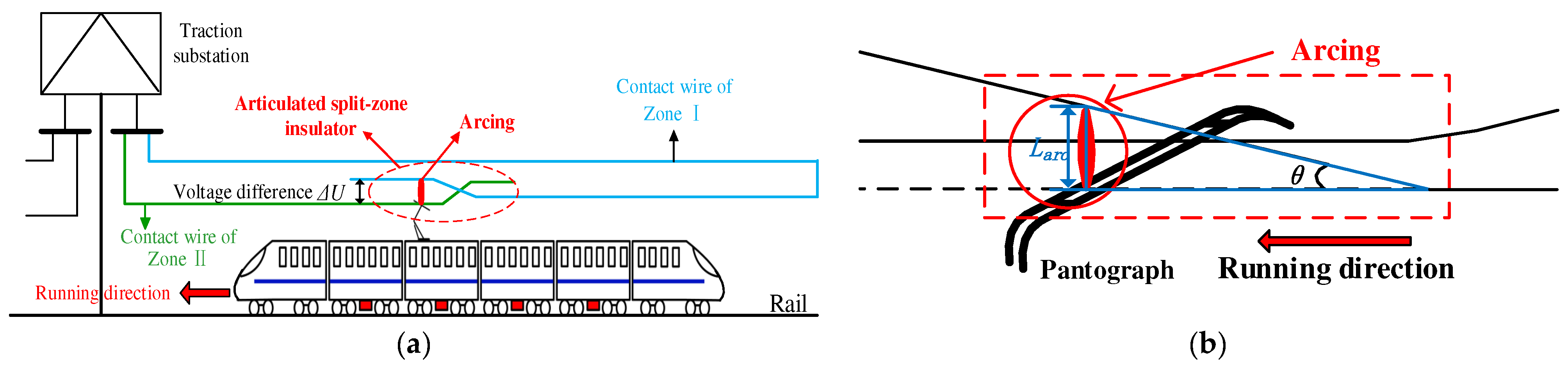
2. Arcing Mechanism of the Articulated Split-Zone Insulator

This paper takes the actual structure of a five-span articulated split-zone insulator of a high-speed railway in China as an example. The arcing mechanism is analyzed when EMUs leave the split-zone insulator. The schematic diagram of arcing is shown in Figure 1.
As shown in Figure 1, the split-zone region contact wire consists of zone I and zone II. Considering that the two zone contact wires of the articulated split-zone insulator are powered by the same traction substation, the initial voltage is the same. According to the running direction of EMUs shown in Figure 1a, the process where the pantograph current collection from zone I to zone II of contact wire is termed as leaving the articulated split-zone insulator. At this time, there is a certain gap between the PC contact point and the contact wire of zone I, which will generate a certain voltage difference ΔU as shown in Figure 1b. When the voltage difference reaches a certain value, a breakdown may occur between the slide and the contact wire of zone I. This results in the occurrence of arcing, known as the PC arc.
According to the empirical Formula (1) derived from breakdown voltage experiments [29], the smaller the distance between the slide and the contact wire of zone I, the lower the breakdown voltage ΔU required for the train to pass through the split-zone insulator. This makes it easier for split-zone region arcing to occur.
Δ U = 25.4 d + 6.64 d

3. Modeling of Articulated Split-Zone Insulator Arcing

3.1. Black-Box Arc Model

This study utilizes the Habedank black-box arc model to simulate PC arcing generated during the process of high-speed trains through the articulated insulator. The Habedank black box arc model combines the Cassie model and the Mayr model in series. Consequently, it overcomes the disadvantages of the Cassie arc model, which is only suitable for describing arcs with high currents, and the Mayr arc model, which is only suitable for describing arcs with small currents during the current zero-crossing (CZC) stage [11,30,31]. Therefore, the Habedank black box arc model is more suitable for describing the PC arc. Its mathematical expression is shown in (2).
d g c d t = 1 τ c ( e i E 0 2 g c ) d g m d t = 1 τ m ( i 2 P 0 g m ) 1 g = 1 g c + 1 g m
where e is the arc voltage per unit length of the arc column, τ is the arc time constant, i is the arc current, E0 is the arc voltage gradient, P0 is the arc dissipation power, and g is the arc conductivity.

3.2. Extension of Parameters for the Black Box Arc Model

Considering the influence of the dynamic characteristics [32] of the PC system on arc generation during the actual operation of EMUs, this paper extends the parameters E0 and P0 in (2) to be functions of the arc length Larc.
In terms of the arc voltage gradient E0, based on the research results from reference [33], it is found that the arc voltage gradient is approximately proportional to the arc length. Therefore, the arc voltage gradient can be extended as shown in (3).
E 0 = k 1 L a r c
where k1 represents the proportionality coefficient.
In terms of the arc dissipation power P0, previous researchers have summarized experimental data on different types of arcs and concluded that the arc dissipation power is approximately proportional to the arc conductivity and arc length, exhibiting an exponential function relationship [11]. Its expression can be written as shown in (4).
P 0 = k 2 g α L a r c β
where k2 represents the arc dissipation power dielectric coefficient, and α and β are constants.
To simplify calculations, this paper neglects changes in the arc shape when the EMUs leave the split-zone region. It assumes that the distance between the PC contact point and the contact wire of zone I is the arc length Larc. In addition, the parameter V represents the train’s operating speed, t denotes the duration of the arc after its occurrence, and θ signifies the angle between the contact wire of zone I and the horizontal plane.
Then, according to the arcing mechanism of the split-zone insulator, the dynamic variation process of the arc length Larc when the EMUs leave the split-zone region can be described as shown in (5).
L = V t tan θ
Based on the above discussion, the arc model developed in this paper for EMUs departing from articulated insulators is shown in (6). In addition, the simulation experiments were conducted using the MATLAB_2023a experimental platform. The software has powerful matrix and data processing capabilities, ensuring high accuracy in arc model calculations.
d g c d t = 1 τ c ( e i k 1 2 ( V t tan θ ) 2 g c ) d g m d t = 1 τ m ( i 2 k 2 g α ( V t tan θ ) β g m ) 1 g = 1 g c + 1 g m

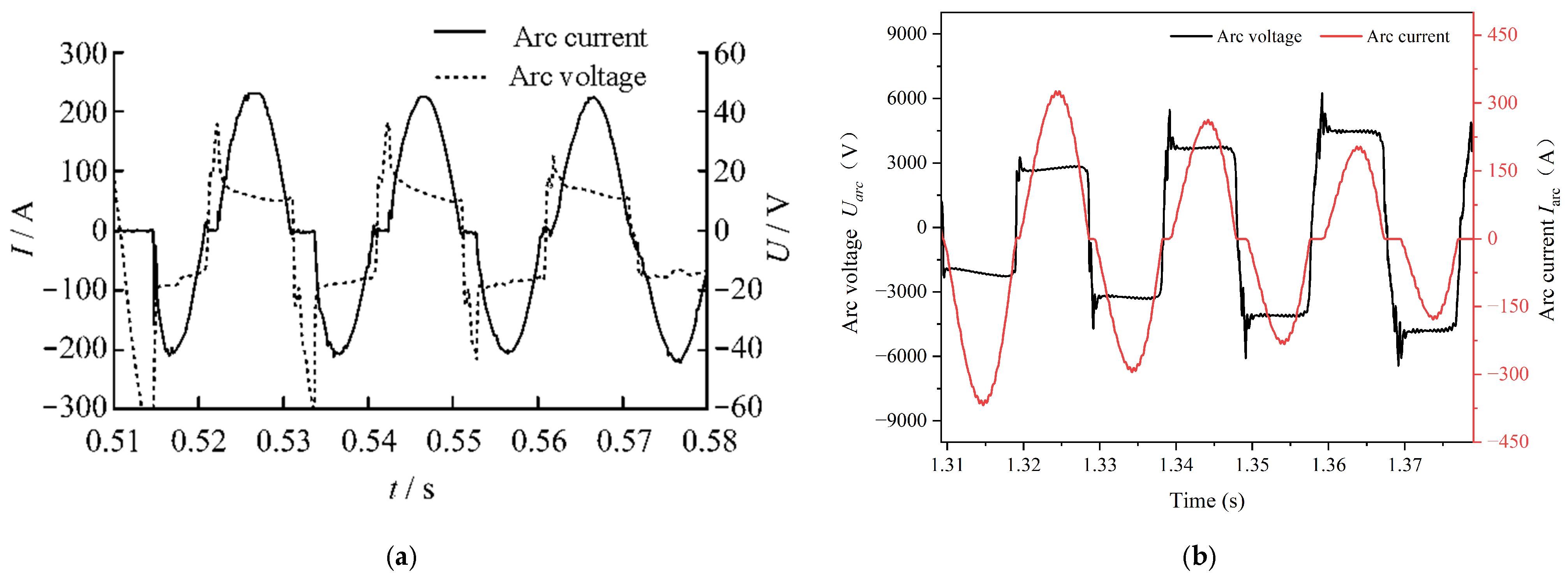
3.3. Model Validation

Due to the difficulty in obtaining actual PC arc test data, this paper adopts a method of waveform and electrical characteristic similarity for validation. This method involves comparing the simulated arc voltage and arc current obtained from simulation calculations with existing test results. If the waveforms are similar and the electrical characteristics are comparable, it can be demonstrated that the extension of arc parameters developed in this paper is reasonable. Thus, the arc numerical simulation model established in this paper can be used to describe the PC arc phenomenon occurring when the EMUs leave the articulated split-zone insulator. Additionally, this paper carries out simulation experiments using the five-span articulated split-zone insulator circuit model and the power supply network electrical model constructed in reference [1].
In reference [34], simulation experiments were carried out with a pantograph sliding speed of 8 km/h, and the waveforms of arc voltage and current were measured as shown in Figure 2a. The dynamic process of the pantograph gradually approaching the contact wire is consistent with the trend of distance variation when the EMUs leave the articulated insulator. The simulated waveforms of arc voltage and arc current obtained from simulation are shown in Figure 2b. It can be seen that the simulated arc waveforms also exhibit typical arc characteristics such as unstable arc voltage regions and arc CZC regions. Additionally, the amplitude of the unstable arc voltage region and the peak value of the arc current decrease gradually with the continuous burning of the arc within each cycle. Therefore, the arc model constructed in this paper is effective and can be used to study the electrical characteristics of articulated split-zone insulator arcs.

4. Experimental Results and Discussion

To investigate the variation rule of the arc during split-zone insulators under different operating conditions of the EMUs, a large number of simulation experiments have been carried out under various factors. To clearly demonstrate the influence of different factors on the waveform of arc voltage and current, only selected data sets are analyzed in this section.

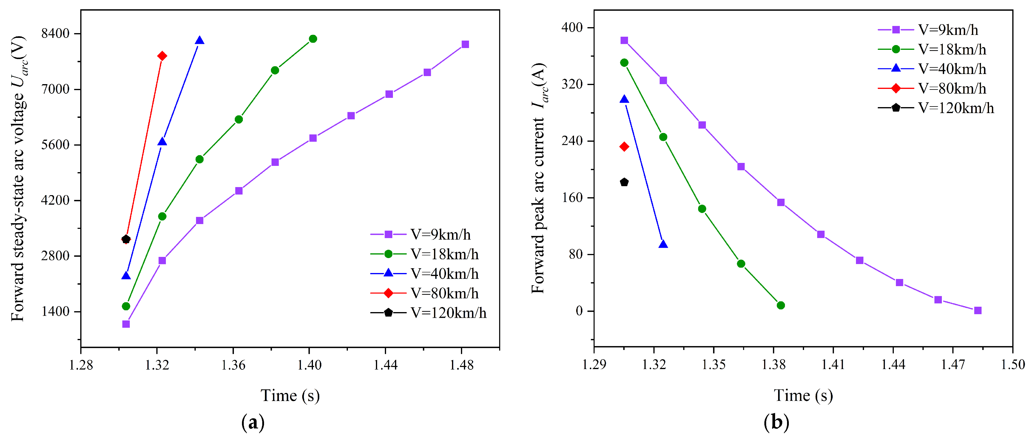
4.1. The Influence of Train Speed on Arcing Electrical Characteristics

To investigate the arcing electrical characteristics when the EMUs leave the split-zone insulator at different running speeds, simulation experiments were conducted by varying the velocity parameter V in the arc model. The experimental results are shown in Figure 3.
It can be seen in Figure 3 that the voltage waveform during EMU departure from the split-zone insulator shows a general upward trend. Additionally, within one arcing cycle, the voltage waveform resembles a saddle shape. Meanwhile, the arcing current exhibits a trend of attenuation in oscillation. Furthermore, over time, the duration of the arc near zero at the zero-crossing point increases, indicating prolonged ‘zero-rest’ time of the PC arc, a trend accentuated with higher train speeds.
This is primarily because, with increasing speed, under the same split-zone insulator structure, the distance between the pantograph contact point and the non-working branch of the PC contact wire increases. Ignoring changes in arc shape, a quicker increase in arc length occurs with increasing speed. According to (4), an increase in arc length results in varying the velocity parameter V in the arc model. The experimental results are shown in Figure 3.
It can be seen in Figure 3 that as the EMUs leave the split-zone insulator, the arcing voltage waveform exhibits an overall upward trend. Moreover, the voltage waveform within one cycle of arcing approximates a saddle shape. Meanwhile, the arcing current shows a trend of oscillation attenuation. Additionally, with the passage of time, the duration of the arc remaining close to zero at the zero-crossing point increases, indicating an increase in the “zero-rest” time of the PC arc. This trend becomes more pronounced with increasing train speed.
The aforementioned is primarily because, with increasing speed, under the same split-zone insulator structure, the distance between the pantograph contact point and the non-working branch of the PC contact wire increases. Ignoring changes in arc shape, a quicker increase in arc length occurs with increasing speed. According to (4), an increase in arc length results in greater dissipated power, reducing the probability of arc reignition and thereby accelerating arc extinction. Consequently, as time elapses, the arcing voltage gradually transitions into the voltage differential between the two contact wires, while the arcing current steadily decreases toward zero.
In addition, to further describe the numerical variations in arcing voltage and arcing current as the train leaves the split-zone insulator, this study extracts the forward steady-state arc voltage and forward arc peak current of the PC arc under different train speeds, as shown in Figure 4.
It can be seen in Figure 4a that at the same train speed, the forward steady-state arcing voltage increases with time. For example, at a train speed of 9 km/h, the forward steady-state arcing voltage increases from 1087 V to 8137 V. At a speed of 18 km/h, the forward steady-state arcing voltage increases from 1536 V to 8273 V. Additionally, at the same moment, the forward steady-state arcing voltage increases with the increase in train speed. For example, at t = 1.32 s, when the train speed increases from 9 km/h to 120 km/h, the forward steady-state arcing voltage increases from 1087 V to 3324 V. As the PC arc is an AC arc, the reverse steady-state arcing voltage also exhibits an increasing trend with speed.
In Figure 4b, the forward arcing peak current decreases with time and shows an overall downward trend. For example, at a train speed of 9 km/h, the forward arcing peak current decreases from 382 A to 0.5 A. At the same arcing moment, at t = 1.3 s, the forward arcing peak currents for the EMUs running at speeds of 9, 18, 40, 80, and 120 km/h are 382, 350, 298, 232, and 181A respectively. It also shows a downward trend. According to the Formula (5), it is evident that with an increase in the speed grade of the EMUs, the arcing length increases more rapidly per unit time. This would result in a sharp increase in arc dissipation power. Additionally, the increase in arc length leads to an enlargement of the convection area between the arc column and the surrounding air. This accelerates the cooling rate of the arc, causing the arc diameter to contract and increasing the arc resistance. Consequently, the arcing voltage gradually increases. However, due to the unique structure, when EMUs leave the articulated split-zone insulator, the traction current originates from both the working branch of the split-zone insulator and the arcing current. At the same arcing moment, as the speed grade increases, the traction current also increases. Nevertheless, as the electric locomotive continues to move forward, the rate of increase in arcing dissipated power far surpasses the rate of increase in input power. Therefore, at a macroscopic level, there is a positive correlation between the working branch current and speed, while the arcing current exhibits a negative correlation with the train speed.

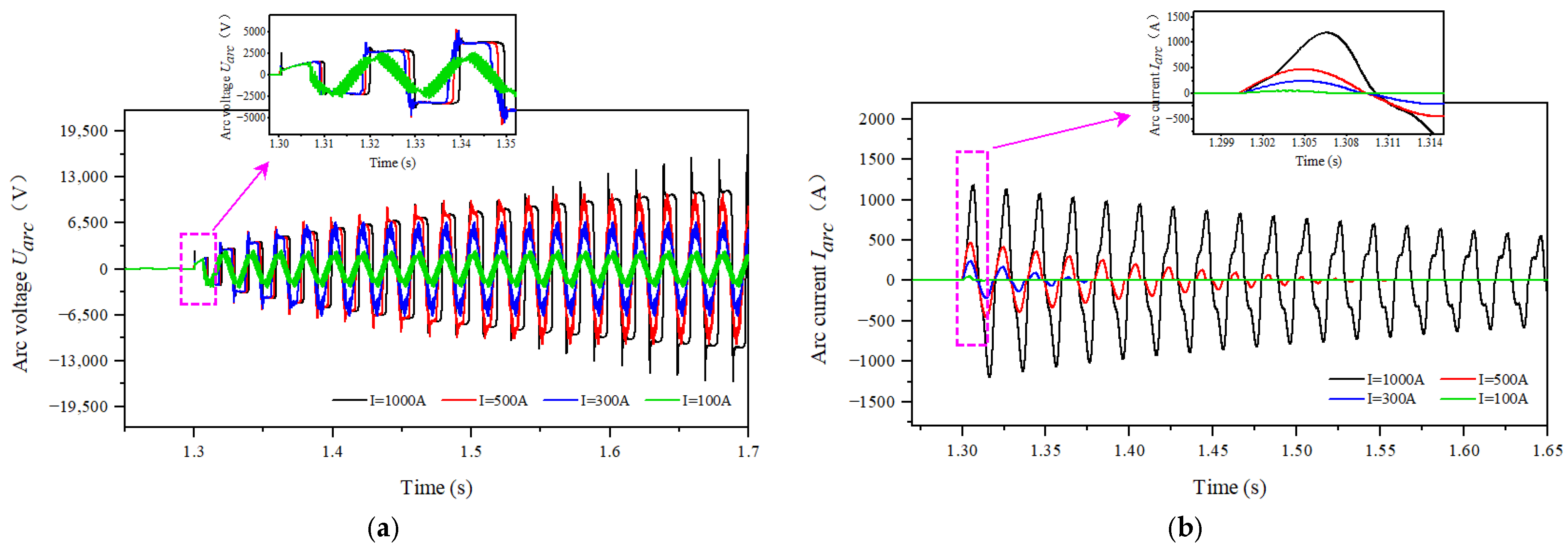
4.2. The Influence of Voltage Difference on the Arcing Electrical Characteristics

According to the arcing mechanism, the voltage difference between the slide and the non-working branch of the contact wire is the primary cause of arcing when EMUs leave the split-zone insulator. Therefore, simulation experiments were conducted to investigate the arcing characteristics of the split-zone insulator under different voltage differences of 100 V, 500 V, 800 V, 1200 V, and 3000 V. The voltage difference was achieved by adjusting the impedance parameters of the contact wire on both sides of the split-zone insulator. The experimental results are shown in Figure 5.
Figure 5a shows that the arcing peak voltage increases gradually with the increase in voltage difference between the two zones of contact wire. For example, when the voltage difference increases from 100 V to 3000 V, the forward arcing peak voltage increases from 477 V to 3131 V. Additionally, as the voltage difference level increases, both the forward arcing peak current and the number of CZC also increase, as shown in Figure 5b. This results in more frequent arcing re-ignitions, making the arc difficult to extinguish, and significantly extending the arcing duration. For example, within the first arcing cycle, as the voltage difference increases, the forward arcing peak current increases from approximately 51 A to 556 A, and the arcing duration increases from 2 ms to 85 ms.
The aforementioned is because the voltage difference is the primary cause of the formation and maintenance of the PC arc. As the voltage difference between the slide and the non-working branch of the contact wire gradually increases, the energy input into the split-zone insulator arc also increases. At the same distance, the air medium becomes more prone to breakdown, making it easier for the split-zone insulator arc to occur. Moreover, at this point, both the arc voltage and arc current are higher. Conversely, if the voltage difference is too small, it becomes difficult to sustain the arc’s dissipation power, resulting in a shorter duration of arc burning and making it easier for the arc to extinguish.

4.3. The Influence of Current Collection Size on the Arcing Electrical Characteristics

To investigate the impact of the current collection size on the arcing electrical characteristics, simulation experiments were conducted under different current collection sizes of 100 A, 300 A, 500 A, and 1000 A. The experimental results are shown in Figure 6.
Figure 6 shows that under the same current collection conditions, the arc voltage consists of stable and unstable regions. As time elapses, the peak voltage in the unstable region of the arc gradually increases, while the peak current of the arc gradually decreases. For example, when the current collection size is 500 A, the forward arcing peak voltage increases from 1089 V to 6248 V, while the arcing current peak decreases from 393 A to 0 A. Furthermore, as the current collection size increases from 100 A to 1000 A, both the forward steady-state arcing voltage, arcing current peak, and arcing duration show a gradual increase.
The aforementioned is mainly because, with a larger current collection size, there is a greater redistribution value of current when the EMUs pass through the split-zone insulator. Additionally, an increase in the current collection size directly results in an increase in voltage drop on the working branch of the contact wire. This leads to an increase in voltage difference between the two contact wires. Under the combined effect of both factors, the input power of the arc increases, making it difficult to extinguish.

4.4. The Influence of Structural Forms on Arcing Electrical Characteristics

The impact of different structural forms of articulated split-zone insulators on pantograph arcing electrical characteristics in actual operational lines is quite complex. This paper primarily focuses on the influence of different mechanical structures of the split-zone region on the inclination angle of the contact wire and its effect on arcing. Based on the actual structure of the split-zone region in a railway section in Zhengzhou, it is observed that the angles (θ) between the non-working branch of contact wire and the horizontal plane when the EMUs pass through the three-span, four-span, and five-span spilt-zone insulator are 0.252°, 0.527°, and 0.367°, respectively. Therefore, simulations can be conducted by adjusting the parameter θ in the arcing model, and the experimental results are shown in Figure 7.
It can be seen from the experimental results in Figure 7 that in the initial stage of arcing, the voltage and current waveforms do not show significant variation with different spans. This is mainly because the input power of the arc is primarily determined by the voltage difference between the slide and the non-working branch of the contact wire and the size of the current collection by the EMUs. When the operating parameters of the EMUs are consistent, the input power of the split-zone region arc remains consistent, and there is not much difference in arc length among different spans in the initial stage of arcing. Therefore, different structural forms of articulated split-zone insulators have little impact on the initial voltage and initial current of the arc. However, after the second arcing cycle, it can be seen that the arc voltage is higher for the four-span compared to the three-span and five-span, the current decay rate is faster, and the total arcing time is the shortest.
According to Equation (5), as the inclination angle θ increases, the distance between the pantograph contact point and the non-working branch of the contact wire increases per unit time, leading to a longer arc length. At this point, under the influence of airflow, the arc disassociation is stronger, causing the arc voltage to rise to maintain the conductive channel. Meanwhile, the dissipated power of the arc increases, resulting in a faster decay rate of current per unit time and a decrease in the total arcing time.

5. Simulation Results and Discussion

To further elucidate the relationship between different operational parameters of the EMUs and arcing time, a statistical analysis of all simulation data was conducted. Based on this result, the entropy weight method was proposed for calculating the impact strength of each operational parameter on arcing time.

5.1. Determination of Arcing Time

Through the simulation analysis of the electrical characteristics of the split-zone region arc in Section 3 of the article, it is evident that the arc current value remains constant at 0 before the arc occurs. When the EMUs completely leave the split-zone insulator, the train is powered by the contact wire of zone II. At this point, the arc extinguishes between the contact wire of zone I and the slide, and the arc current value drops to 0 again. Therefore, the arcing time of the split-zone region arc can be determined through the arc current waveform, as shown in Figure 8.
Therefore, the arcing time tarc can be calculated using Equation (7).
t a r c = t 2 t 1

5.2. Calculation of the Influence Weights of Each Indicator

To determine the impact strength of different operational conditions of the EMUs on the arcing time in the split-zone region, the entropy weight method is proposed for calculation. The entropy weight method reflects the uncertainty and disorder within each indicator based on the information entropy of each indicator. It can determine the weights of each indicator and comprehensively evaluate the influence of each factor on the decision-making results. This method, while considering the importance of each indicator comprehensively, can effectively handle the correlation between indicators, providing an objective basis for decision-making. The calculation process is illustrated in Figure 9.
To ensure that each indicator has the same scale and magnitude, it is necessary to standardize the experimental data since the arcing time is negatively correlated with the speed V of the EMUs, and positively correlated with the voltage difference ΔU between the two contact wires and the current collection I of the EMUs. Therefore, the indicator V needs to be reverse-standardized, while the indicators ΔU and I need to be forward-standardized. This study adopts the range method to standardize each indicator, and the calculation formula is as follows (8).
F o r w a r d : n i j = σ i j M i n ( σ i j ) M a x ( σ i j ) M i n ( σ i j ) R e v e r s e : n i j = M a x ( σ i j ) σ i j M a x ( σ i j ) M i n ( σ i j ) i = 1 , 2 , , m j = 1 , 2 , , n
where σij represents the standardized data of the i-th sample in the j-th indicator. This study primarily focuses on the impact weights of V, ΔU, and I on arcing time, totaling three evaluation indicators, hence n = 3. The calculation formula for the information entropy Ej of each indicator is shown in (9).
E j = K i = 1 m p i j ln ( p i j ) P i j = σ i j / i = 1 n σ i j
where K = 1/ln(m) and Pij represents the proportion of the i-th sample under the j-th indicator. The weight Wj of each indicator can be calculated using (10).
g j = 1 E j W j = g j / j = 1 3 g j
where gj represents the information utility value of each indicator in the equation.
Through calculation, the impact strength of each evaluation index for the arc duration time can be obtained. They are WV = 0.338, WΔU = 0.333, and WI = 0.329, respectively. That is, the impact strength of the running speed of the EMUs on the arc duration time of the split-zone region is the largest, while the impact strength of the current collection is the smallest. When the EMUs pass through the articulated split-zone insulator, this conclusion can provide technical references for optimizing the operational parameters of the EMUs to reduce the erosion of the contact wire and slide by the arc.

6. Conclusions

This paper conducts a series of simulation analyses on the sensitive factors affecting the electrical characteristics of PC arcing when EMUs pass through the split-zone insulator. The main conclusions obtained are as follows:
(1)
An arc simulation model suitable for EMUs leaving articulated split-zone insulators was established. This model considers the dynamic variation process of the distance between the slide and contact wire and was verified through comparison with existing research results.
(2)
The impact strengths of different operational parameters on the arc duration time of the articulated split-zone insulator were obtained. The article proposes using the entropy weight method to calculate the experimental data. It was found that train speed has the largest impact strength on the arc duration time, while current collection has the smallest impact strength on the arc duration time.
(3)
When a train passes through the split-zone region, the erosion of the slide and contact wire can be reduced by increasing the operating speed, decreasing the voltage difference between the two contact wires of zone I and zone II, and adjusting the mechanical structure of the articulated split-zone insulator.

Author Contributions

The individual contribution of each co-author with regard to the reported research and writing of the paper is as follows. L.P., B.X. and L.C. conceived the idea, T.X., H.Z., Y.L. and Y.S. performed experiments and data analysis, and all authors wrote the paper. All authors have read and agreed to the published version of the manuscript.

Funding

This study was supported in part by the Natural Science Foundation Project of Sichuan Province (No. 24NSFSC7248), China Railway (No. L2023G006), China Academy of Railway Sciences Corporation Limited (No. 2022YJ151), Fundamental Research Funds for the Central Universities (No. 2682024CX001), and the open project of the State Key Laboratory of Traction Power (No. TPL2211).

Data Availability Statement

The sources of all data used in this study are presented in this manuscript.

Conflicts of Interest

Authors Like Pan, Liming Chen, Tong Xing and Haibo Zhang were employed by the company China Academy of Railway Sciences Corporation Limited. The remaining authors declare that the research was conducted in the absence of any commercial or financial relationships that could be construed as a potential conflict of interest.

Nomenclature

PCpantograph–catenary
EMUselectric multiple units
MHDmagnetohydrodynamic
CZCcurrent zero-crossing
List of Symbols
SymbolsMeaning
ΔUvoltage difference
dthe gap between contact surfaces
earc voltage per unit length
τarc time constant
P0arc dissipation power
iarc current
garc conductivity
k1proportionality coefficient
k2arc dissipation power coefficient
Larcarc length
Vtrain’s operating speed
tduration of the arc
tarcarcing time
σijstandardized data
nthe number of evaluation indicators
Pijthe proportion
Ejinformation entropy
Wjimpact weight

References

  1. Liu, Z.; Zhou, H.; Huang, K.; Song, Y.; Zheng, Z.; Cheng, Y. Extended Black-Box Model of Pantograph-Catenary Detachment Arc Considering Pantograph-Catenary Dynamics in Electrified Railway. IEEE Trans. Ind. Appl. 2019, 55, 776–785. [Google Scholar] [CrossRef]
  2. Li, Z.; Li, Z. Study on Electric Spark Caused by Voltage Difference at Section Insulator of Overhead Contact System. Railw. Constr. Technol. 2012, 06, 100–102. (In Chinese) [Google Scholar]
  3. Liu, Z.; Song, Y.; Gao, S.; Wang, H. Review of Perspectives on Pantograph-Catenary Interaction Research for High-Speed Railways Operating at 400 km/h and Above. IEEE Trans. Transp. Electrif. 2023, early access. [Google Scholar] [CrossRef]
  4. Song, Y.; Liu, Z.; Rønnquist, A.; Nåvik, P.; Liu, Z. Contact Wire Irregularity Stochastics and Effect on High-Speed Railway Pantograph–Catenary Interactions. IEEE Trans. Instrum. Meas. 2020, 69, 8196–8206. [Google Scholar] [CrossRef]
  5. Wang, H. Causes and Solutions of Pantograph Carbon Strip Abnormal Wear on Beijing Metro Line 6 West Extension. Urban Mass Transit 2023, 26, 44–49. (In Chinese) [Google Scholar]
  6. Song, Y.; Wang, Z.; Liu, Z.; Wang, R. A spatial coupling model to study dynamic performance of pantograph-catenary with vehicle-track excitation. Mech. Syst. Signal Process. 2021, 151, 107336. [Google Scholar] [CrossRef]
  7. Li, Z.; Wang, C.; Cao, H. Analysis on Automatic Pantograph Lowering of EMU’s on Line B of West Tianjin. Electr. Railw. 2017, 28, 49–52. (In Chinese) [Google Scholar]
  8. Cheng, Y.; Liu, Z.; Huang, K. Transient Analysis of Electric Arc Burning at Insulated Rail Joints in High-Speed Railway Stations Based on State-Space Modeling. IEEE Trans. Transp. Electrif. 2017, 3, 750–761. [Google Scholar] [CrossRef]
  9. Huang, K.; Su, D. Extended Pantograph-Catenary Arc Modeling and an Analysis of the Vehicular-Grounding Electromagnetic Transients of Electric Multiple Units. Energies 2024, 17, 1416. [Google Scholar] [CrossRef]
  10. Yan, X.; Chen, W.; Wang, C.; Li, Z. Computation of Secondary Arc Self-extinction Behavior With the Influence of Wind. Proc. CSEE 2009, 29, 1–6. (In Chinese) [Google Scholar]
  11. Wang, Y.; Liu, Z.; Mu, X.; Huang, K.; Wang, H.; Gao, S. An extended habedank’s equation-based EMTP model of pantograph arcing considering pantograph-catenary interactions and train speeds. IEEE Trans. Power Deliv. 2015, 31, 1186–1194. [Google Scholar] [CrossRef]
  12. Liu, Z.; Yang, Y.; Zhou, H.; Huang, K. Study on the Modeling and Suppression of Arcing Generated by Articulated Split-Zone Insulator in Electrified Railways. IEEE Trans. Transp. Electrif. 2022, 8, 542–552. [Google Scholar] [CrossRef]
  13. Wang, X.; Guo, F.; Li, F.; Liu, Z.; Kou, J. Influence of Surface Roughness of Sliding Friction Pairs on Pantograph-Catenary Contact Resistance. IEEE Trans. Transp. Electrif. 2024, early access. [Google Scholar] [CrossRef]
  14. Yang, Z.; Xu, P.; Wei, W.; Gao, G.; Zhou, N.; Wu, G. Influence of the Crosswind on the Pantograph Arcing Dynamics. IEEE Trans. Plasma Sci. 2020, 48, 2822–2830. [Google Scholar] [CrossRef]
  15. Gao, G.; Yan, X.; Yang, Z.; Wei, W.; Hu, Y.; Wu, G. Pantograph-Catenary Arcing Detection Based on Electromagnetic Radiation. IEEE Trans. Electromagn. Compat. 2018, 61, 983–989. [Google Scholar] [CrossRef]
  16. Gao, G.; Hao, J.; Wei, W.; Hu, H.; Zhu, G.; Wu, G. Dynamics of Pantograph–Catenary Arc During the Pantograph Lowering Process. IEEE Trans. Plasma Sci. 2016, 44, 2715–2723. [Google Scholar] [CrossRef]
  17. Khakpour, A.; Uhrlandt, D.; Methling, R.P.; Gortschakow, S.; Franke, S.; Imani, M.T.; Weltmann, K.D. Impact of temperature changing on voltage and power of an electric arc. Electr. Power Syst. Res. 2017, 143, 73–78. [Google Scholar] [CrossRef]
  18. Xu, Z.; Gao, G.; Wei, W. Characteristics of pantograph-catenary arc under low air pressure and strong airflow. High Volt. 2022, 7, 369–381. [Google Scholar] [CrossRef]
  19. Duan, F.; Song, Y.; Gao, S.; Liu, Y.; Zhu, W.; Lu, X.; Liu, Z. Study on Aerodynamic Instability and Galloping Response of Rail Overhead Contact Line Based on Wind Tunnel Tests. IEEE Trans. Veh. Technol. 2023, 72, 7211–7220. [Google Scholar] [CrossRef]
  20. Song, Y.; Liu, Z.; Gao, S. Current Collection Quality of High-speed Rail Pantograph-catenary Considering Geometry Deviation at 400 km/h and Above. IEEE Trans. Veh. Technol. 2024, early access. [Google Scholar] [CrossRef]
  21. Hu, Z.; Song, Y.; Chen, L.; Duan, F.; Liu, Z.; Feng, X. Experimental and Numerical Exploration of Support Stiffness Influence on the Current Collection Quality of Pantograph and Overhead Conductor Rail System. IEEE Trans. Transp. Electrif. 2023, early access. [Google Scholar] [CrossRef]
  22. Song, Y.; Lu, X.; Yin, Y.; Liu, Y.; Liu, Z. Optimization of Railway Pantograph-Catenary Systems for Over 350 km/h Based on an Experimentally Validated Model. IEEE Trans. Ind. Inform. 2024, 20, 7654–7664. [Google Scholar] [CrossRef]
  23. Zhang, R.; Jiang, F.; Xue, L. Experimental Study on Wire Melting Control Ability of Twin-Body Plasma Arc. Chin. J. Mech. Eng. 2024, 37, 30. [Google Scholar] [CrossRef]
  24. Chen, T.; Liu, J.; Liu, G.; Xiao, H.; Li, C.; Liu, X. Experimental Study on Titanium Alloy Cutting Property and Wear Mechanism with Circular-arc Milling Cutters. Chin. J. Mech. Eng. 2023, 36, 57. [Google Scholar] [CrossRef]
  25. Yang, Y.; Gao, H.; Zhang, M.; Su, Z.; Hu, M.; Jin, M.; Liu, S. Research on the Influence of Pantograph Catenary Contact Loss Arcs and Zero-Crossing Stage on Electromagnetic Disturbance in High-Speed Railway. Energies 2024, 17, 138. [Google Scholar] [CrossRef]
  26. He, D.; Zhou, H.; Lan, Z.; Wang, W.; Zeng, J.; Yu, X.; Shen, Z. Solid-state Circuit Breaker Based on Cascaded Normally-on SiC JFETs for Medium-voltage DC Distribution Networks. Prot. Control. Mod. Power Syst. 2024, 9, 32–46. [Google Scholar] [CrossRef]
  27. Xu, H.; Liu, W.; Yin, J.; Li, X.; Zhao, L.; Sun, C. Study on electrical characteristics of pantograph-catenary arc during contact loss. Railw. Stand. Des. 2021, 65, 147–153. [Google Scholar]
  28. Lu, B.; Liu, Z.; Wang, X.; Song, Y.; Zhang, Q.; Wu, S.; Tao, G. Influence of Electric Traction Drive System Harmonics and Interharmonics on the Vibration of Key Locomotive Components. IEEE Trans. Veh. Technol. 2023, 72, 12830–12844. [Google Scholar] [CrossRef]
  29. Zhou, H.; Liu, Z.; Deng, Y.; Yang, Y.; Gao, S. Study on the Suppression of Arcing Generated by Articulated Split-zone Insulator in Electrified Railways. Power Syst. Technol. 2023, 47, 2583–2593. [Google Scholar]
  30. Lin, X.; Pan, C.; Luo, D.; Sun, Y. Series DC Arc Simulation of Photovoltaic System Based on Habedank Model. Energies 2020, 13, 1416. [Google Scholar] [CrossRef]
  31. Yu, D.; Sun, H. Mechanism of Arcing in High Speed Train Based on Pantograph Arc Dynamic Model. Urban Mass Transit 2020, 23, 54–57. (In Chinese) [Google Scholar]
  32. Andrea, M. The Electrical Behaviour of Railway Pantograph Arcs. Energies 2023, 16, 1465. [Google Scholar] [CrossRef]
  33. Swierczynski, B.; Gonzalez1, J.; Teulet, P.; Freton, P.; Gleizes, A. Advances in low-voltage circuit breaker modeling. J. Phys. D Appl. Phys. 2004, 37, 595–609. [Google Scholar] [CrossRef]
  34. Wang, W.; Wu, G.; Zhao, Y.; Gao, G.; Wang, B. Experimental Study of Electrical Characteristics on Pantograph Arcing. Electr. Energy Manag. Technol. 2012, 6, 5–10+27. (In Chinese) [Google Scholar] [CrossRef]
Figure 1. Schematic diagram of arcing when EMUs leave the articulated insulator. (a) Schematic diagram of EMUs passing the articulated insulator; (b) Schematic diagram of the dynamic process.
Energies 17 03883 g001
Figure 2. Split-zone insulator arc model validation. (a) The experimental results of arc voltage and current in reference [34]; (b) The waveform of arc voltage and current simulated in this paper.
Energies 17 03883 g002
Figure 3. The electrical characteristics of arcing at different operating speeds. (a) The arc voltage waveform at different operating speeds; (b) The arc current waveform at different operating speeds.
Energies 17 03883 g003
Figure 4. The forward steady-state arc voltage and forward peak arc current values at different train speeds. (a) The forward steady-state arc voltage at different operating speeds; (b) The forward peak arc current at different operating speeds.
Energies 17 03883 g004
Figure 5. The electrical characteristics of arcing at different voltage difference. (a) The arc voltage waveform at different voltage differentials; (b) The arc current waveform at different voltage differentials.
Energies 17 03883 g005
Figure 6. The electrical characteristics of arcing at different current collection conditions. (a) The arc voltage waveform at different current collection conditions; (b) The arc current waveform at different current collection conditions.
Energies 17 03883 g006
Figure 7. The electrical characteristics of arcing at different split-zone insulator structures. (a) The arc voltage at different split-zone insulator structures; (b) The arc current at different split-zone insulator structures.
Energies 17 03883 g007
Figure 8. Determining the arc ignition time.
Energies 17 03883 g008
Figure 9. The flowchart of the entropy weight method.
Energies 17 03883 g009
Disclaimer/Publisher’s Note: The statements, opinions and data contained in all publications are solely those of the individual author(s) and contributor(s) and not of MDPI and/or the editor(s). MDPI and/or the editor(s) disclaim responsibility for any injury to people or property resulting from any ideas, methods, instructions or products referred to in the content.

