Article

Analysis of Vibration Electromechanical Response Behavior of Poly(Vinylidene Fluoride) Piezoelectric Films

1
School of Mechanics and Construction Engineering, Jinan University, Guangzhou 510632, China
2
School of Robotics, Guangdong Polytechnic of Science and Technology, Zhuhai 519090, China
3
College of Packaging Engineering, Jinan University, Guangzhou 510632, China
*
Author to whom correspondence should be addressed.
Energies 2024, 17(16), 3886; https://doi.org/10.3390/en17163886 (registering DOI)
Submission received: 19 June 2024 / Revised: 27 July 2024 / Accepted: 1 August 2024 / Published: 6 August 2024
(This article belongs to the Special Issue Electrocatalytic Energy and Resource Conversion)

Abstract

:
Studying the electromechanical response behavior of piezoelectric thin films under different loading conditions is of great value for the development and optimization of piezoelectric sensors and flexible portable electronic devices. This paper establishes the theory of large deflection vibration of rectangular four-edge simply supported piezoelectric thin films using the energy method, and analyzes the electromechanical response characteristics of vibration force (including resonant frequency and nonlinear vibration). Meanwhile, the electromechanical response behavior of Poly(vinylidene fluoride) (PVDF) films under different loading conditions (static and harmonic vibration) is analyzed. The study investigates the nonlinear vibration characteristics and resonance frequency variations under different film sizes and thickness conditions in the case of various loading conditions. The developed model can predict the resonance frequency associated with the plate dimensions. This study is of great significance for the research and application of laminated piezoelectric film sensors.

1. Introduction

The rapid advancement of artificial intelligence and the Internet of Things underscores the necessity of manufacturing flexible and portable electronic devices to enable human–machine interfaces. Among these crucial electronic components, strain and stress sensors play a pivotal role in signal acquisition, significantly enhancing the efficiency of human–machine interfaces. So far, mainstream strain/stress sensors include transistor capacitive [1,2], resistive [3], frictional electric, and piezoelectric sensors [4]. Furthermore, organic piezoelectric materials have garnered significant attention in the fabrication of flexible and wearable electronic devices due to their low density, excellent biocompatibility, flexibility, and ease of processing compared to their inorganic counterparts [5,6].
Piezoelectric sensors are self-powered sensors that utilize the piezoelectric effect for measurement, detection, and control purposes. The piezoelectric effect refers to the change in electric potential or charge when some materials (for example, sphalerite [7,8], boracite [9], tourmaline [10], zincite [11], LiTaO3 [12], Rare earth calcium borate [13], or PIN-PMN-PT [14]) are subjected to force. Piezoelectric sensors are characterized by fast response speed, high accuracy, wide measurement range, small size, light weight, and resistance to high temperatures and corrosion. They have a wide range of applications in medicine [15], engineering [16,17], and smart products. Piezoelectric films are flexible, lightweight, and highly resilient membranes. Their ease of fabrication brings great convenience in engineering applications. Poly(vinylidene fluoride) (PVDF) and its copolymer polyvinylidene fluoride-trifluoroethylene (P(VDF-TrFE))((C2H2F2)n) are among the most commonly utilized materials [18]. Compared with traditional piezoelectric materials (such as ceramic piezoelectric plates), PVDF exhibits wide frequency response, a large dynamic range, high sensitivity for force-to-electricity conversion, excellent mechanical properties, high mechanical strength, and easy impedance matching in acoustic applications [19].
In addition to their piezoelectric properties, PVDF films also exhibit excellent mechanical performance, maintaining stable characteristics under various vibration frequencies and flexural deformations. Studies have shown that PVDF films can undergo nonlinear vibrations under mechanical vibration [20] and possess strong energy conversion capabilities. These features make PVDF films a promising material for energy harvesting, effectively converting mechanical energy into electrical energy in vibrational environments, thus providing a stable energy source for mechanical systems [21]. Piezoelectric devices typically function under resonance conditions in the majority of measurement and energy harvesting applications, resulting in increased vibrations and enhanced energy conversion. The resonant frequency can be tuned by altering the characteristics of the device, its geometric configuration, and mechanical composition. Hence, determining and forecasting the resonant frequency is essential to verify the suitability of these devices for particular applications and for enhancing their efficiency through optimization [22,23]. Beeby et al. [24] argued that resonance frequency plays a critical role in these systems as it determines the frequency at which maximum energy can be harvested. Different transduction mechanisms (piezoelectric, electromagnetic, or electrostatic) have different resonance frequency considerations. In their article [25], Kim et al. argued that nonlinear effects in vibration energy harvesting can influence device performance. Hence, this study also conducts research in the field of resonance frequency and the patterns of nonlinear vibrations.
In many scenarios where PVDF films are used as sensors, the deformation of the film often equals or exceeds the thickness dimension of the film. Therefore, the large deflection theory adopted in this paper can provide guidance for many engineering applications. Skate [26] stated that when a cantilever beam is used as a carrier for other micro-detection techniques, such as emerging micro-electrical testing probes, its deflection may be slightly higher and enter a state of large deflection. Jeung et al. [27] pointed out that microactuators composed of polyimide and PVDF-TrFE polymers can meet the demand for large vertical displacement deformation while controlling the device size in categories such as micro-zoom lenses, micro-mirrors, micro-valves, and optical applications. In their article [28], Hashmi and Jayatissa used finite element analysis and designed a PVDF layer that can be used to detect the bending of hinges when mechanical devices are in motion (detectable up to a maximum of 90° rotation). In addition, in their article [29], Fu et al. used CoventorWare software to model and simulate composite cantilever beams, optimize design parameters, and achieve large tip deflections.
In this study, an energy method was employed for the parametric investigation of PVDF films, aiming to establish a modeling and analysis method for simply supported structures. In 2005, Mo et al. [30] employed the energy method to analyze the power generation performance of a simply supported, single-crystal, piezoelectric circular diaphragm energy harvester (with different radii for the piezoelectric layer and substrate layer). The researchers conducted a parametric study of the energy harvester to evaluate the influence of various parameters on power generation. In another work [31], Mo C, Davidson J proposed a comprehensive theoretical model for predicting the energy generation performance of energy harvesting devices using compressed piezoelectric circular membranes under pressure fluctuations, and utilized the energy method to determine the total stress on the membrane. In 2022, Viola G et al. [32] utilized a combined piezoelectric acoustic laser vibrometer setup to assess the mechanical oscillations and electrical reaction information of PVDF circular disks with varying diameters across several sound wave frequencies (100 Hz to 10 kHz). They solved the force–electric coupling response of thin plates based on the energy method within the framework of the continuum medium theory. Compared with the theorical method, the energy method could simplify the calculation when solving the dynamic equation and displacement of plate with assumptive displacements.
At the same time, the micro-inertia effect of piezoelectric materials under high frequency or fast loading conditions and the polarization inertia effect when the polarization direction of piezoelectric materials changes or the external electric field is applied to change also have a significant effect on the electromechanical response of piezoelectric materials. In their article [33], Hrytsyna et al. introduce a theoretical framework integrating polarization inertia and flexodynamic effects into thermo-elastic dielectrics. This extends classical theories with gradient-type constitutive equations, offering insights into material behavior under dynamic conditions. Similarly, Qu et al. [34] propose a non-classical theory integrating couple stress and quadrupole polarization effects. It derives comprehensive constitutive relations using variational principles, highlighting its application in predicting flexoelectric effects in bending problems. Meanwhile, Chen et al. [35] investigate the impact of flexoelectric effects on beam deflection and electrical responses. Experimental validation underscores the dominance of flexoelectric effects in practical applications.
Meanwhile, the flexoelectric effect also plays a significant role in the energy harvesting of bending piezoelectric thin plate. Zhang with co-authors [36] conducted a comparison of energy harvesting capabilities between piezoelectric and flexoelectric rings. In their study, they concluded that the flexoelectric ring energy harvester outperforms the piezoelectric counterpart in transverse oscillation-bending dominant vibrations, primarily due to the flexoelectric effect’s sensitivity to strain gradients (specifically bending strain). Chen et al. [35] investigated the forced oscillations of piezoelectric and flexoelectric Euler–Bernoulli beams using dynamic Green’s functions. They concluded that “the dynamic voltage output in open-circuit conditions and the dynamic charge output in short-circuit conditions are primarily influenced by the flexoelectric phenomenon”. It is worth noting that Viola et al. [32] researched the thin circular plate under harmonic loading, but the result of the experiment was quite different compared with the result obtained by the theoretical method, which is the same as this article.
PVDF, as a material with excellent mechanical and electrical properties, has been extensively researched by many scholars both domestically and internationally. In the biomedical field, PVDF piezoelectric films have been designed and utilized for applications such as replacing hair cells in cochlear implants [32,37,38], measuring throat movements [39], and monitoring blood pressure [40]. In engineering monitoring applications, PVDF films have been developed for hydrophones [41] and pressure measurements inside pipes [42], among other uses. In the aforementioned research, we find that PVDF films, serving as sensors, play a crucial role in both biomedical and engineering monitoring applications. Several studies have used PVDF films for structural and mathematical derivations to analyze the feasibility and accuracy of piezoelectric films in the researched areas, and have optimized them accordingly. It is worth noting that a significant portion of the data mentioned above were obtained through experiments for reverse-deducing piezoelectric signals, as well as for analyzing the electromechanical response behavior using finite element methods. In these studies, it can be observed that the shape, dimensions, boundary conditions, and external loading of the PVDF films used vary significantly. Based on von Kármán’s contribution to the large deflection bending theory of circular thin plates [43], most studies have focused on the analysis and calculation of circular PVDF films, with boundary conditions mostly being fixed supports. Therefore, further research is needed on the response of rectangular PVDF films in the case of different external loading and the resulting electrical potential energy under simply supported conditions on all four sides.
This paper investigates the mechanical and electrical responses of PVDF piezoelectric films under various loading conditions and conducts parameter studies, focusing on the effects of dimensions and thickness of thin plates on deflection, resonant frequency, nonlinear vibration patterns, and energy harvesting. A high-precision mathematical model framework which lays the foundation for similar linear mathematical descriptions in piezoelectric systems is established, providing some guidance for machine learning through the establishment of formulas for voltage and force. The organization of this paper is as follows. In Section 2.1, we provide a detailed description of the problems to be addressed, including a model diagram and boundary conditions. In Section 2.2, we use the energy method to solve the mechanical response of rectangular thin films with four simply supported sides under different loadings (static and harmonic loading). In Section 3, we present a method for obtaining the potential voltage based on the piezoelectric constitutive equation. Section 4 provides the effects of thin film dimensions, thickness, and loading on the obtained potential voltage through solving integral equations and finite element simulations, as well as the effects of dimensional parameters on resonant frequency and nonlinear vibration. Finally, several conclusions are drawn in Section 5.

2. Theoretical Formulation

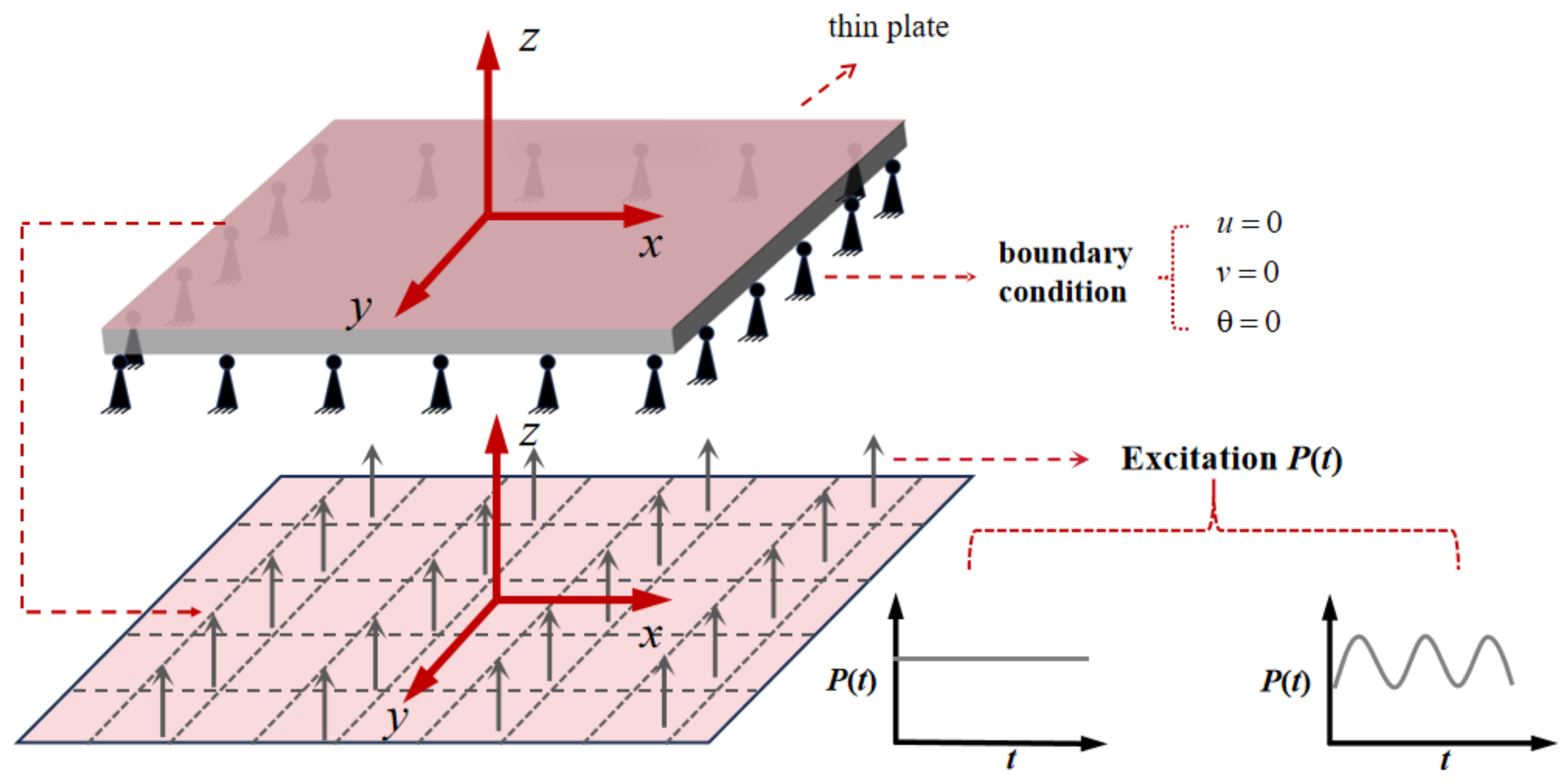
2.1. Mathematical Model

In previous studies, the vibration of piezoelectric plates has been extensively discussed [17], and some research has shown that numerical analysis can already address certain issues related to piezoelectric plates [44]. Among them, Hosseini-Hashemi and colleagues [45] proposed a three-dimensional model for piezoelectric-enhanced circular or ring plates, whereas Zhang and his team [46] performed a three-dimensional assessment of vibrational behavior in multi-layer piezoelectric composite plates.
In this study, the plate we calculate is isotropic. The piezoelectric effect caused by deformation in isotropic plates under mechanical vibration is a result of constitutive level coupling, rather than the solution of equations. The constitutive equations of piezoelectric materials clearly demonstrate the interdependence between elastic and electric effects [47]. The equation for solving this problem is the result of the coupling of boundary conditions and force conditions. Therefore, for mechanical vibration and static loading problems of piezoelectric thin plates, we adopt the approach of solving the elastic problem first and then computing the piezoelectric problem [31,48]. In order to propose the motion equations for the PVDF plate, a simplified method is presented below, referencing and summarizing the theory of Mo [31]. A rectangular PVDF thin plate, with its simply supported boundary conditions, is represented in a Cartesian coordinate system x y z , with length 2a, width 2b, and thickness h . Figure 1 depicts this thin plate, subjected to an external uniform distributed force of magnitude p ( t ) . When pressure is applied, the thin plate deforms, resulting in the generation of charges on the piezoelectric material.
Based on the theory of large deflection in thin plates, the uniform pressure performs work that is transformed into elastic strain energy within the PVDF thin plate. This energy includes both stretching strain caused by membrane stretching and bending strain. [49,50]. Moreover, under the condition of a large deflection deformation of the plate, the bending deformation energy generated by out-of-plane bending can be neglected [51] in a static condition.

2.2. Equation of Motion

2.2.1. Static Loading Condition

The strain energy V S generated by the deformation of the membrane using stress–strain functions is given by
V S = a a b b h / 2 h / 2 ( σ x ε x + σ y ε y + σ z ε z + τ x y γ x y + τ x z γ x z + τ y z γ y z ) d x d y d z
According to Timoshenko’s large deflection theory of plates [51], the value of σ z , τ x z , τ y z can be ignored, so the strain energy V s can be simplified as
V S = a a b b h / 2 h / 2 ( σ x ε x + σ y ε y + τ x y γ x y ) d x d y d z
where 2 a and 2 b represent the length of two edges of the rectangle, and x , y , z is the coordinate orientation depicted in Figure 1. σ x , σ y , τ x y represent the stress in the direction of the coordinate axis. ε x , ε y , γ x y represent the strain in the direction of the coordinate axis. h is the thinness of this membrane.
The relationships between displacements and strains are as follows:
ε x = u x + 1 2 w x 2
ε y = v y + 1 2 w y 2
γ x y = v x + u y + w x w y
where w is the transverse displacement in the positive z direction, u is the deflection in the x direction, and v is the deflection in the y direction.
Similarly, the relationships between stresses and displacements are as follows:
σ x = Y ( 1 v ) 2 u x + 1 2 w x 2 + v v y + 1 2 w y 2
σ y = Y ( 1 v ) 2 v y + 1 2 w y 2 + v u x + 1 2 w x 2
τ x y = Y 2 ( 1 + v ) u y + v x + 1 2 w x w y
where Y is Young’s modulus and ν is the Poisson ratio.
According to Hook’s law, replacing stress with strain in Equation (2), the simplified strain energy is obtained:
V S = E 1 ν 2 a a b b h / 2 h / 2 ε x 2 + ε y 2 + 2 ν ε x ε y + 1 2 ( 1 ν ) γ x y 2 d x d y d z
We then substitute Equations (3)–(5) into Equation (9) to obtain the strain energy expressed by displacements.
V S = k b b a a u x 2 + u x w x 2 + v y 2 + v y w y 2 + 1 4 w x 2 + w y 2 2 + 2 v u x v y + 1 2 v y w x 2 + 1 2 u x v y 2 + ( 1 v ) 2 u y 2 + 2 u y v x + v x 2 + 2 u y w x w y + 2 v x w x w y d x d y
where k = Y h 1 v 2 .
When we use the energy method, we must assume that the displacements u , v , w are appropriately expressed in each special case. Obviously, these equations must satisfy the boundary conditions and contain several arbitrary parameters. The magnitude of the parameters is determined by the virtual displacement principle. In this problem, u , v , w must be zero on the boundary. In addition, it can be known from the symmetry that w is an even function of x and y , and u and v are odd functions of x and y , respectively. The displacement is taken as the following formula:
u = c 1 sin π x a cos π y 2 b
v = c 2 sin π y b cos π x 2 a
w = w 0 cos π x 2 a cos π y 2 b
where w 0 is the maximum deflection of the film at x = 0 , y = 0 and c 1 , c 2 are constants.
V S = Y h 18432 a 3 b 3 ( 1 ν 2 ) × 128 a 2 b 2 ( 9 a 2 π 2 ( 8 c 2 2 + c 1 2 ( 1 + ν ) ) 9 b 2 π 2 ( 8 c 1 2 c 2 2 ( 1 + ν ) ) 128 a b c 1 c 2 ( 1 + ν ) ) 768 a b π 2 ( 4 b 3 c 1 + 4 a 3 c 2 + a 2 b c 1 ( 1 3 ν ) + a b 2 c 2 ( 1 3 ν ) ) w 0 2 + 9 ( 9 a 4 + 2 a 2 b 2 + 9 b 4 ) π 4 w 0 4
The constants c 1 , c 2 in Equation (14) are derived based on the requirement that the elastic potential energy resulting from the membrane’s stretching at an equilibrium position is minimized, and therefore V s c 1 = 0 , V s c 2 = 0 .
c 1 = ( 3 π 2 ( 36 b 4 π 2 ( 1 + ν ) + 8 a 4 ( 32 ( 1 + ν ) + 9 π 2 ( 1 + 3 ν ) ) s ) w 0 2 ) ( 648 a 5 π 4 ( 1 + ν ) + 648 a b 4 π 4 ( 1 + ν ) + f )
c 2 = ( 3 π 2 ( 36 a 4 π 2 ( 1 + ν ) + 8 b 4 ( 32 ( 1 + ν ) + 9 π 2 ( 1 + 3 ν ) ) s ) w 0 2 ) 648 a 4 b π 4 ( 1 + ν ) + 648 b 5 π 4 ( 1 + ν ) + f f = a 3 b 2 ( 4096 ( 1 + ν ) 2 81 π 4 ( 65 2 ν + ν 2 ) ) s = a 2 b 2 ( 9 π 2 ( 33 4 ν + 3 ν 2 ) + 64 ( 1 + 2 ν + 3 ν 2 ) )
The principle of virtual work can be used to find the maximum transverse deflection w 0 by balancing the work carried out by an external uniform force p 0 ( t ) with the change in strain energy caused by a virtual displacement.
V S w 0 = b b a a q cos π x 2 b cos π y 2 a d x d y
w 0 can be obtained by solving Equation (17)
w 0 = w 01 / ( π 2 ( ( ( e h w 02 + w 03 + w 04 + w 05 ) / w 06 ) ) ) 1 3 w 01 = 16 a 1 / 3 b 1 / 3 p 0   1 / 3 w 02 = 72 a 8 π 2 ( 256 + 81 π 2 ) ( 1 + ν ) + 72 b 8 π 2 ( 256 + 81 π 2 ) ( 1 + ν ) w 03 = a 6 b 2 ( 28672 ( 1 + ν ) 2 + 18432 π 2 ( 9 2 ν + ν 2 ) 81 π 4 ( 601 50 ν + 25 ν 2 ) ) w 04 = a 6 b 6 ( 28672 ( 1 + ν ) 2 + 18432 π 2 ( 9 2 ν + ν 2 ) 81 π 4 ( 601 50 ν + 25 ν 2 ) ) w 05 = 2 a 4 b 4 ( 4096 ( 33 + 35 ν 3 ν 2 + ν 3 ) 1152 π 2 ( 65 + 67 ν 3 ν 2 + ν 3 ) + 81 π 4 ( 137 + 139 ν 3 ν 2 + ν 3 ) )

2.2.2. Vibration Loading Condition

When we consider the vibration problem (the loading is a harmonic force), we need to consider the bending deformation energy of the plate.
The bending deformation energy of the plate is as follows:
d V b = D 2 2 w x 2 2 + 2 w y 2 2 + 2 ν 2 w x 2 2 w y 2 + D ( 1 ν ) 2 w x y 2 d x d y
It can be simplified by Green’s formula
2 w x 2 2 w y 2 2 w x y 2 d x d y = w x 2 w x y d x + w y 2 w y 2 d y
For a rectangle without free edges but with simply supported edges and built-in edges, d x = 0 , 2 w y 2 = 0 on the boundary, where x is a constant, and d y = 0 , w x = 0 on the boundary, where y is a constant. Then, Equation (19) could be reduced:
d V b = D 2 ( 2 w ) 2 d x d y
where D = Y h 3 12 ( 1 ν 2 ) is the bending stiffness.
The above assumed solution of displacement is brought into Equation (21)
V b = ( a 2 + b 2 ) 2 Y h 3 π 4 w 0   2 384 a 3 b 3 ( 1 ν 2 )
The total deformation energy is the sum of two parts of energy V = V S + V b which includes a linear part and a nonlinear part. Because the external uniform force is equal to p ( t ) = p 0 e i ω t , the potential energy V E (equal to negative W E ) of sinusoidal vibration is expressed as:
V E = W E = a a b b p ( t ) w d x d y
The form of kinetic energy is
K = ρ h 2 a a b b ( u ˙ 2 + v ˙ 2 + w ˙ 2 ) d x d y
By calculating the integral, we can obtain the kinetic energy:
  K = 1 2 h ρ a b w ˙ 0 2 + 9 a b π 4 ( k 11 k 12 ) 2 w ˙ 0 4 ( k 13 + k 14 ) 2 + 9 a π 4 ( k 13 + k 14 ) 2 w ˙ 0 4 b ( k 23 + k 24 ) 2 k 11 = 36 b 4 π 2 ( 1 + ν ) + 8 a 4 ( 32 ( 1 + ν ) + 9 π 2 ( 1 + 3 ν ) ) k 12 = a 2 b 2 ( 64 ( 1 + ν ) ( 1 + 3 ν ) + 9 π 2 ( 33 + ν ( 4 + 3 ν ) ) ) k 13 = 648 a 5 π 4 ( 1 + ν ) + 648 a b 4 π 4 ( 1 + ν ) k 14 = a 3 b 2 ( 4096 ( 1 + ν ) 2 81 π 4 ( 65 + ( ν 2 ) ν ) ) k 21 = 36 a 4 π 2 ( ν 1 ) + 8 b 4 ( 32 ( ν 1 ) + 9 π 2 ( 3 ν 1 ) ) k 22 = a 2 b 2 ( 64 ( 1 + ν ) ( 3 ν 1 ) + 9 π 2 ( 33 + ν ( 3 ν 4 ) ) )
We can obtain the following condition by Hamilton’s principle.
t 1 t 2 ( δ V s + δ V E δ K ) d t = t 1 t 2 [ ( V s w 0 + V E w 0 ) w 0 K w ˙ 0 w ˙ 0 ] d t = 0
Then,
m 3 w ¨ 0 3 + m 1 w ¨ 0 + k 1 w 0 + k 3 w 0 3 = f
According to Equation (27), the value of large deflection w 0 can be found.

3. The Piezoelectric Film’s Electric Potential

The strain of the piezoelectric material is composed of the superposition of stress and electric field.
ε i = S i j E σ j + d k i E K ( i = 1 , 2 , 3……6 ; K = 1 , 2 , 3 )
where S i j E is the flexibility coefficient and d k i is the piezoelectric constant. The first term in the formula shows the contribution of stress σ j to the total strain when the applied electric field E K is zero. The second part of this equation denotes the influence of the applied electric field E K on the overall strain. Similarly, the electric induction vector component is influenced by both the stress and the applied electric field:
D i = d i k σ k + ε i m σ E m ( i , m = 1 , 2 , 3 ; k = 1 , 2 , 3……6 )
We consider that the plate only polarizes in the direction of thickness ( E 1 = 0 , E 2 = 0 ), and the piezoelectric constitutive equations for the plate can be simplified as:
ε x = 1 Y ( σ x + ν σ y ) + d 31 E 3
ε y = 1 Y ( σ y + ν σ x ) + d 31 E 3
γ x y = 2 ( 1 + ν ) Y τ x y + d 31 E 3
D 3 = d 31 ( σ x + σ y + τ x y ) + ( 33 T E 3 )
where 33 T is the dielectric permittivity, D 3 is the component of the electric induction vector, and E 3 is the component of the electric field vector.
Stresses and strains provide a means to determine the energy contained within a small volume element of the membrane:
d u = 1 2 σ x ε x + 1 2 σ   y ε y + 1 2 τ x y γ x y + 1 2 D 3 E 3 = 1 2 ε x σ x + 1 2 σ y ε y + 1 2 τ x y γ x y + d 31 ( σ x + σ y + τ x y ) 2 E 3 + 1 2 33 T E 3 2
The overall energy stored in the membrane can be calculated by integrating the energy across the differential volume over the entire membrane volume.
U = a a b b h / 2 h / 2 d u d x d y d z
The electric field E 3 is replaced by V h , where V is the applied voltage and distinguished according to the voltage V g e n to generate the charge expression. The charge equation consists of two components: one denotes the charge induced by external loading, and the other signifies the applied voltage input. The charge produced in the absence of an applied electric field is such that
Q g e n = d U d V = ( ( a 2 + b 2 ) d 31 Y π 2 w 0   2 ) ( 16 a b ( 1 + ν ) )
From the relation Q = C V , the open-circuit capacitance is
C f r e e = 4 a b 33 T h
The voltage on the electrode is
V g e n = Q g e n C f r e e = ( a 2 + b 2 ) d 31 Y h π 2 w 0   2 64 a 2 b 2 ( 1 + ν ) 33 T
Therefore, in the case of stretching, the electric energy generated by the uniformly distributed pressure p 0 is:
U g e n = 1 2 Q g e n V g e n = ( a 2 + b 2 ) 2 d 31 2 Y 2 h π 4 w 0 4 2048 ( 1 + ν ) a 3 b 3   2 33 T
For the acquisition of electric energy in static problems and harmonic vibration problems, their difference lies in the difference in the value of w 0 , so only the displacement in the case of different external loads is required, and the potential and electric energy generated on the electrode can be obtained.

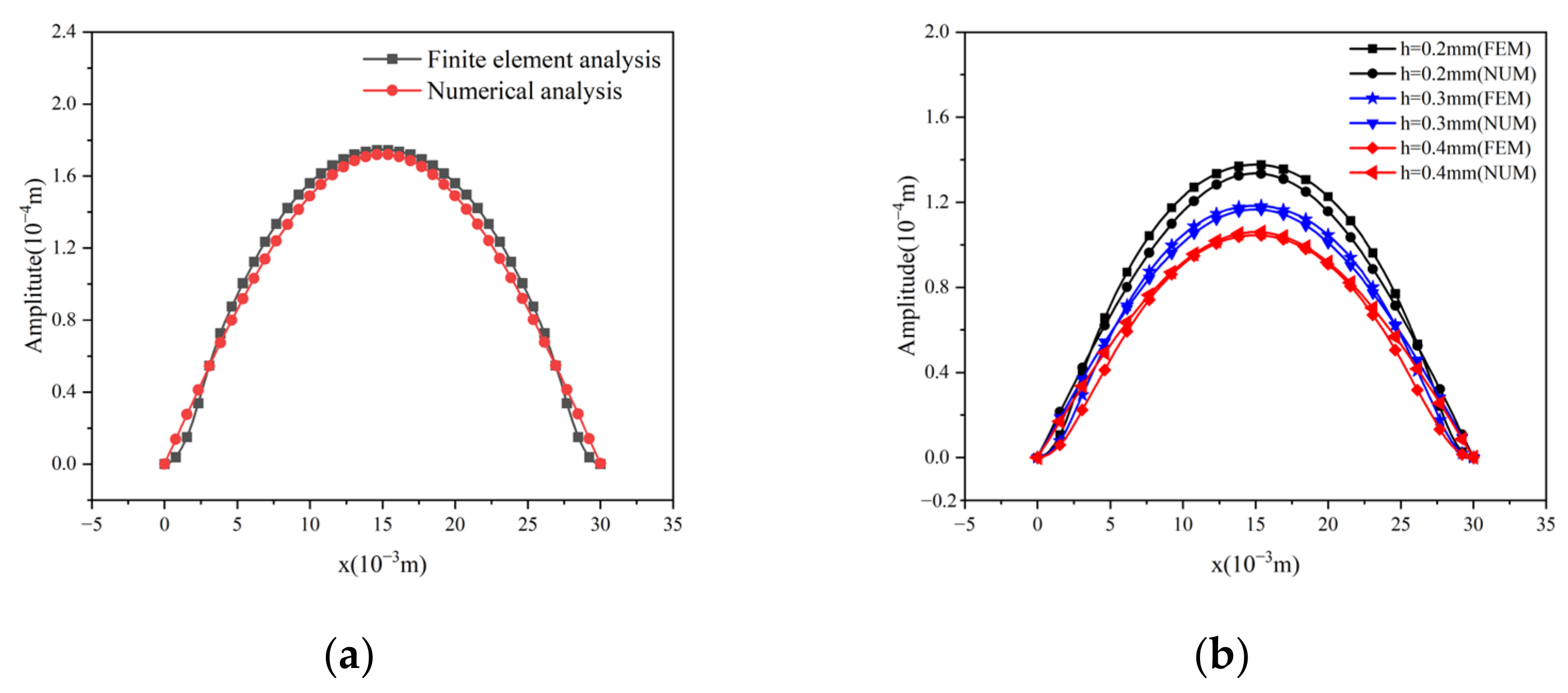
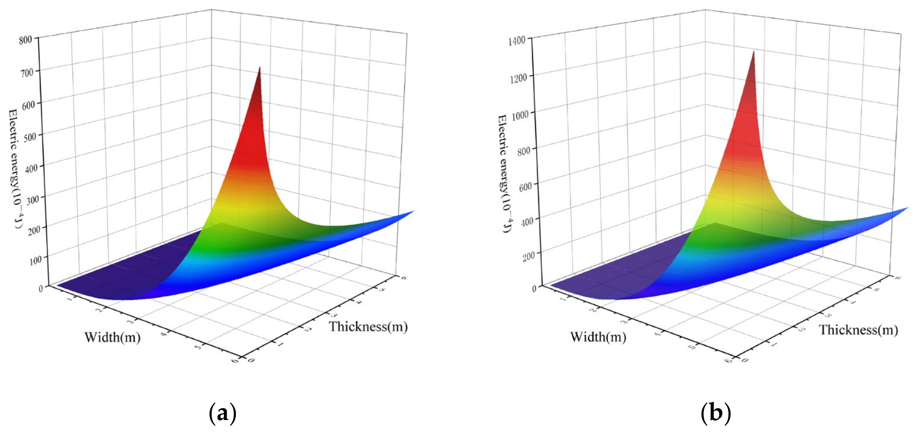
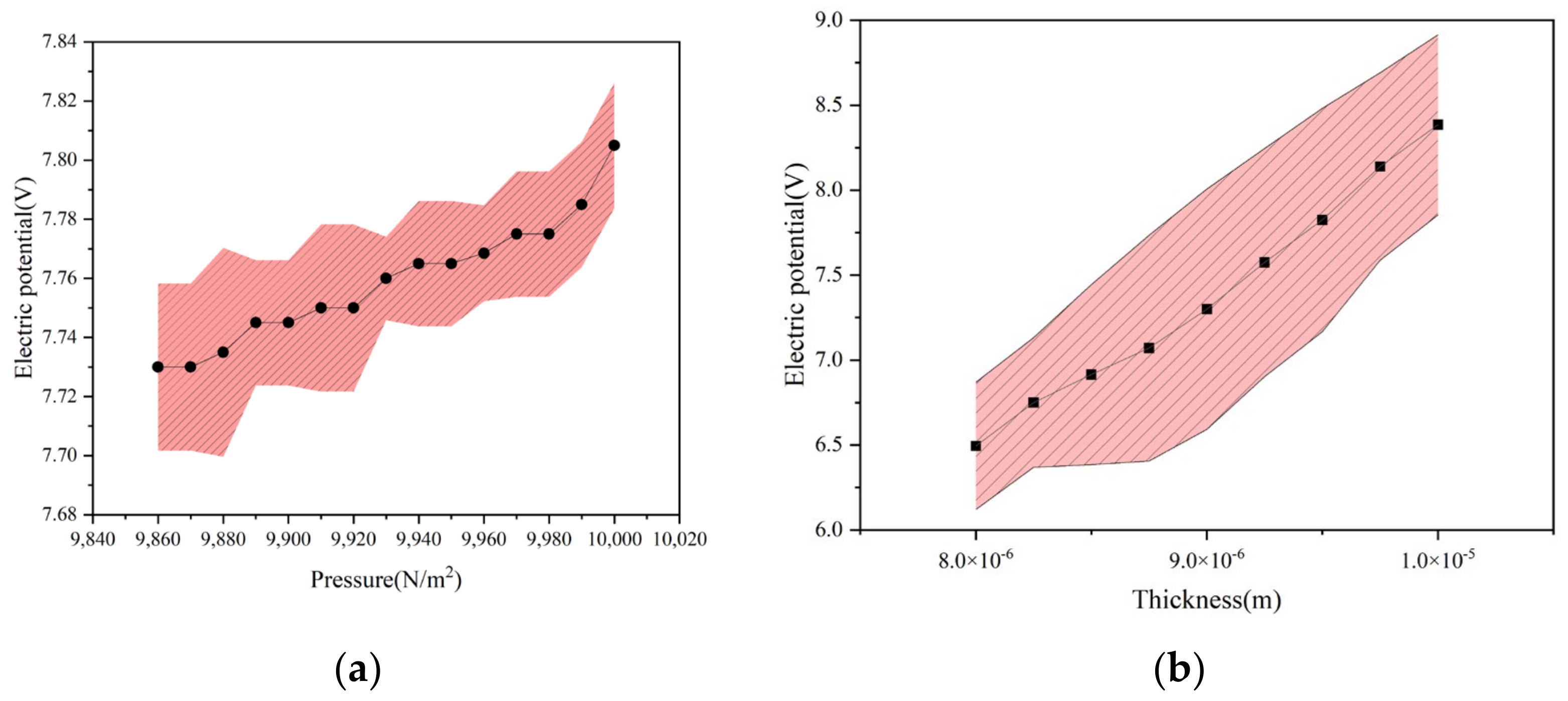
4. Simulation Results and Analysis

In Section 2.2, we simplified the static loading model, ignoring the bending deformation energy in the strain energy. In order to verify the rationality of the comprehensive model and test the effect of ignoring bending, the deflection equation of uniform pressure source was adopted. The energy harvesting performance of the rectangular membrane composed of PVDF was tested. We assumed that the deflection of the rectangular film can be obtained by repeatedly applying mechanical stress over a period of time. It was assumed that a uniform pressure of 10 N/m2 is applied to the rectangular film. In Table 1, the mechanical properties of the material are summarized. The properties utilized in this analysis are derived from PVDF material provided by a reputable measurement company.
Next, according to the electric energy formula (Equation (39)), we realized that the amount of the electric energy depends on a certain extent on the deflection of the film, so we first compared the deflection calculated by the theoretical model with the deflection calculated by the finite element. As shown in Figure 2a, we compared the deflections of rectangular thin films of a b = 1 , h = 0.1 mm under uniform pressure. Subsequently, as shown in Figure 2b, different thicknesses were used for comparative study. Through the analysis of the two figures, we can find that the finite element and theoretical calculation results are in good agreement.
After determining the reliability of the deflection, we studied the amount of electric energy obtained by the piezoelectric film. Figure 3a,b shows the amount of the energy obtained by the film in the case of uniform pressure. In these figures, we can find that the electric potential increases with the increase in the thickness and width. In the case of the increase in the width, the increase trend of the potential acquisition is obviously larger than that of thickness. In order to test the reliability of the potential calculated by Equation (38), we calculated the electric potential of the film with different thickness and size, and compared the numerical results with the finite element analysis results; the results are shown in Figure 4a,b. Comparing the data of Figure 4, we find that the error between the results obtained through numerical calculation and the results obtained through finite element calculation is not large, and the average error of pressure is 0.2%, followed by the average error of thickness being 14.7%. Based on these two data, the accuracy and reliability of the formula were verified.
For the vibration problem, the size-to-thickness ratio of the plate we researched was about 50–600. In this case, the plate could be calculated using traditional thin plate theory. By considering the linear solution of Equation (27), Figure 5a reports the function of frequency and film size. Subsequently, Figure 5 is the Fourier transform of the displacement time curve of the thin plate under the harmonic excitation force. The linear frequency of each plate of different sizes can be clearly identified by constructing a linear simple harmonic response function. And when the thickness condition changes, a similar function can also be obtained to express the linear frequency of the structure. And we also could find that the natural frequency of thin plate increases with decreasing b. We can observe that the natural frequency calculated by the energy method is in good agreement with the natural frequency calculated using the finite element method. Some of the differences that can be observed can be considered as nonlinear effects.
In order to solve the nonlinear problem, we adopted the first-order perturbation method to solve the free vibration under undamped conditions [52]. The solution was obtained by ignoring the nonlinear mass term ( m 3 = 0 ). The amplitude of the nonlinear vibration equation can be expressed by the following formula
A = 4 k 1 3 k 3 w 2 w 0 2 1
where A is the motion amplitude of the plate center and w0 is the natural frequency of the system of Figure 5. The k1, k3 are the coefficients of Equation (27).
Figure 6 shows the nonlinear free vibration of the existing structure. Similarly, considering that the nonlinear mass term can be neglected, the problem of nonlinear undamped forced vibration (due to external loading) is also proposed. The scheme holds that if the loading is a harmonic force, the structure will vibrate when the applied load is in a stable state. This problem has a third-order polynomial to control.
K A 3 + ( 1 Ω 2 ) A 1 = 0
where K = 3 k 3 4 k 1 ( p k 1 ) 2 , A = k 1 p α ¯ , and Ω = w w 0 . Here, α ¯ is the initial assumed displacement which is used in the first-order perturbation method.
In Figure 6a, the amplitude diagram shows a rigid behavior ( K 3 > 0 ); that is, under the condition of nonlinear vibration, the material properties of the film have a behavior similar to the increase in stiffness, which represents the nonlinear resonance frequency increasing with the increase in the vibration deflection of the film. Figure 6b represents that when the deflection of thin plate is smaller than 30.76 times compared with the thickness of thin plate, the difference between the nonlinear frequency and the linear frequency is only 1%, where the resonance frequency in the case of large deflection could be approximated by the linear case. Figure 7 shows three sets of curves, in which the smaller plate has a higher frequency. The amplitude in Figure 7 is the A term in Equation (40). In the case of nonlinear vibration, the resonance frequency of the piezoelectric plate is up to the magnitude of the vibration amplitude, but in the case of linear vibration, its resonance frequency is up to the size. In Figure 8, the sweep frequency (without damping) of nonlinear vibration is numerically reflected. It can be found that the trend of nonlinear resonance frequency is similar in the two figures.
In the following analysis, we obtained the relationship between the potential and the deflection under different size conditions, as shown in Figure 9. We found that when the plate has the maximum deflection, the amount of the obtained potential is also the maximum value. In Figure 9, we can see that the potential is in good agreement with the displacement. It can also be seen in Figure 9a that when the frequency is closer to the resonance frequency of the thin plate, the obtained potential is larger. The same result can also be obtained in Figure 9b,c. We performed a numerical frequency sweep, as shown in Figure 9d, and the potential obtained at the resonance frequency of the thin plate also had a maximum value.
As seen from Figure 10a, with the increase in the thickness of the plate, the resonance frequency which obtains the maximum electrical potential also rises. In Figure 10b, as the area of a rectangular thin plate remains constant while its width and thickness increase, the resonant frequency, which corresponds to the frequency of maximum electrical potential, decreases.
In Equation (39), the amount of the electric energy obtained by the piezoelectric thin plate is related to the displacement, and the displacement is caused by the external force. As shown in Figure 11a,b, we found that the displacement is related to the amount of the electric energy obtained. The larger the displacement, the larger the exponential growth of the electric energy obtained, and the magnitude of the loading is related to the electric energy. With the increase in the loading, the obtained electric energy also increases steadily. In addition, we also swept the frequency and explored the relationship between the frequency and the obtained electric energy. As shown in Figure 12, we used the numerical calculation of the resonance frequency and the potential of the plate under different thicknesses. It can be noticed that with the increase in the thickness of the thin plate, the natural frequency of the thin plate gradually increases, and the obtained electric potential also increases. And the frequency dependence of electrical energy on the thickness of the piezoelectric film is highly nonlinear. The results are consistent with the structure of the finite element simulation (Figure 10a).

5. Conclusions

In this paper, the electromechanical response behavior of the rectangular four-sided simply supported piezoelectric film is given under two different external loading conditions, including static response analysis in the case of uniform pressure and resonance frequency analysis in the case of harmonic loading.
For the static part, the influence of the two variables of film size and thickness on the obtained potential and electric energy in the case of the same external force is mainly explored. It is found that the obtained potential increases with the increase in thickness and increases with the increase in size.
For the vibration part, this paper compares the resonance frequency and deflection solved by the energy method with the simulation results of the finite element method, and finds that the results are almost in good agreement. For the film size and thickness, the linear resonance frequency, nonlinear resonance frequency, and electromechanical response are analyzed. By comparing the theoretical results with the finite element results, it is found that the linear resonance frequency decreases with increasing film area, and increases with increasing thickness. It is worth noting that when analyzing the nonlinear resonance frequency, it is found that the film has a hardening behavior, that is, the nonlinear resonance frequency is relative to the deformation. When the deflection increases, the nonlinear resonance frequency also has an upward trend, which is similar to the case of increasing Young’s modulus. When the amplitude of the thin plate is smaller than 30.76 times thickness, the error of frequency between linear and nonlinear cases is less than 1% (the classical thin plate theory—the size thickness ratio of the plate we selected is about 50–600).

Author Contributions

Methodology, S.H.; Software, J.Z. and T.J.; Writing—original draft, X.W., T.J. and J.X.; Supervision, J.T. and W.Z; Funding acquisition, J.T. and W.Z. All authors have read and agreed to the published version of the manuscript.

Funding

This research was funded by the National Natural Science Foundation of China (12102143), the Natural Science Foundation of Guangdong Province (2024A1515012384), the Fellowship of China Postdoctoral Science Foundation (2022M711333), and the People’s Republic of China Department of Education of Guangdong Province of China (No. 2023ZDZX3065).

Data Availability Statement

The original contributions presented in the study are included in the article, further inquiries can be directed to the corresponding author.

Acknowledgments

Thanks to P.F. Hou for supporting this article.

Conflicts of Interest

The authors declare no conflict of interest.

References

  1. Schwartz, G.; Tee, B.C.K.; Mei, J.; Appleton, A.L.; Kim, D.H.; Wang, H.; Bao, Z. Flexible polymer transistors with high pressure sensitivity for application in electronic skin and health monitoring. Nat. Commun. 2013, 4, 1859. [Google Scholar] [CrossRef] [PubMed]
  2. Mannsfeld, S.C.; Tee, B.C.; Stoltenberg, R.M.; Chen, C.V.H.; Barman, S.; Muir, B.V.; Sokolov, A.N.; Reese, C.; Bao, Z. Highly sensitive flexible pressure sensors with microstructured rubber dielectric layers. Nat. Commun. 2010, 9, 859–864. [Google Scholar] [CrossRef] [PubMed]
  3. Choong, C.L.; Shim, M.B.; Lee, B.S.; Jeon, S.; Ko, D.S.; Kang, T.H.; Bae, J.; Lee, S.H.; Byun, K.E.; Im, J. Highly stretchable resistive pressure sensors using a conductive elastomeric composite on a micropyramid array. Adv. Mater. 2014, 26, 3451–3458. [Google Scholar] [CrossRef]
  4. Xie, L.; Zhai, N.; Liu, Y.; Wen, Z.; Sun, X. Hybrid Triboelectric Nanogenerators: From Energy Complementation to Integration. Research 2021, 2021, 9143762. [Google Scholar] [CrossRef] [PubMed]
  5. Stadlober, B.; Zirkl, M.; Irimia-Vladu, M. Route towards sustainable smart sensors: Ferroelectric polyvinylidene fluoride-based materials and their integration in flexible electronics. Chem. Soc. Rev. 2019, 48, 1787–1825. [Google Scholar] [CrossRef] [PubMed]
  6. Ribeiro, C.; Sencadas, V.; Correia, D.M.; Lanceros-Méndez, S. Piezoelectric polymers as biomaterials for tissue engineering applications. Colloids Surf. B Biointerfaces 2015, 136, 46–55. [Google Scholar] [CrossRef] [PubMed]
  7. Giniyatova, S.; Dauletbekova, A.; Baimukhanov, Z.; Vlasukova, L.; Akilbekov, A.; Usseinov, A.; Kozlovskiy, A.; Akylbekovа, A.; Seitbayev, A.; Karipbayev, Z. Structure, electrical properties and luminescence of ZnO nanocrystals deposited in SiO2/Si track templates. Radiat. Meas. 2019, 125, 52–56. [Google Scholar] [CrossRef]
  8. Deore, S.; Navrotsky, A. Oxide melt solution calorimetry of sulfides: Enthalpy of formation of sphalerite, galena, greenockite, and hawleyite. Am. Mineral. 2006, 91, 400–403. [Google Scholar] [CrossRef]
  9. Ye, Z.G.; Rivera, J.P.; Schmid, H.; Haida, M.; Kohn, K. Magnetoelectric effect and magnetic torque of chromium chlorine boracite Cr3B7O13Cl. Ferroelectrics 1994, 161, 99–110. [Google Scholar] [CrossRef]
  10. Krambrock, K.; Pinheiro, M.; Guedes, K.; Medeiros, S.; Schweizer, S.; Spaeth, J.-M. Correlation of irradiation-induced yellow color with the O− hole center in tourmaline. Phys. Chem. Miner. 2004, 31, 168–175. [Google Scholar] [CrossRef]
  11. Kalendová, A.; Veselý, D.J.P.i.O.C. Study of the anticorrosive efficiency of zincite and periclase-based core–shell pigments in organic coatings. Prog. Org. Coat. 2009, 64, 5–19. [Google Scholar] [CrossRef]
  12. Xiao, X.; Liang, S.; Si, J.; Xu, Q.; Zhang, H.; Ma, L.; Yang, C.; Zhang, X. Performance of LiTaO3 crystals and thin films and their application. Crystals 2023, 13, 1233. [Google Scholar] [CrossRef]
  13. Tian, S.; Li, L.; Lu, X.; Yu, F.; Li, Y.; Jiang, C.; Duan, X.; Wang, Z.; Zhang, S.; Zhao, X. Electrical conduction mechanism of rare-earth calcium oxyborate high temperature piezoelectric crystals. Acta Mater. 2020, 183, 165–171. [Google Scholar] [CrossRef]
  14. Li, X.; Fenu, N.G.; Giles-Donovan, N.; Cochran, S.; Lucas, M. Can Mn: PIN-PMN-PT piezocrystal replace hard piezoceramic in power ultrasonic devices? Ultrasonics 2024, 138, 107257. [Google Scholar] [CrossRef] [PubMed]
  15. Lee, U.-W.; Baik, J.-H.; Lee, S.-G.; Kang, H.S. Transforming polymeric air filters into high-performance supercapacitor electrodes through carbonization and fluorination. Surf. Interfaces 2024, 46, 104061. [Google Scholar] [CrossRef]
  16. Kim, N.I.; Yarali, M.; Moradnia, M.; Aqib, M.; Liao, C.H.; AlQatari, F.; Nong, M.; Li, X.; Ryou, J.H. Piezoelectric Sensors Operating at Very High Temperatures and in Extreme Environments Made of Flexible Ultrawide-Bandgap Single-Crystalline AlN Thin Films. Adv. Funct. Mater. 2022, 33, 2212538. [Google Scholar] [CrossRef]
  17. Gu, Y.; Zhang, T.; Chen, H.; Wang, F.; Pu, Y.; Gao, C.; Li, S. Mini review on flexible and wearable electronics for monitoring human health information. Nanoscale Res. Lett. 2019, 14, 263. [Google Scholar] [CrossRef] [PubMed]
  18. Kalimuldina, G.; Turdakyn, N.; Abay, I.; Medeubayev, A.; Nurpeissova, A.; Adair, D.; Bakenov, Z. A review of piezoelectric PVDF film by electrospinning and its applications. Sensors 2020, 20, 5214. [Google Scholar] [CrossRef] [PubMed]
  19. Shin, Y.-H.; Jung, I.; Park, H.; Pyeon, J.J.; Son, J.G.; Koo, C.M.; Kim, S.; Kang, C.-Y. Mechanical fatigue resistance of piezoelectric PVDF polymers. Micromachines 2018, 9, 503. [Google Scholar] [CrossRef]
  20. Dong, B.; Zhao, R.; Yu, K. Nonlinear combined harmonic resonances of composite cylindrical shells operating in hygro-thermo-electro-magneto-mechanical fields. Compos. Struct. 2024, 331, 117877. [Google Scholar]
  21. Farokhi, H.; Jamia, N.; Jalali, H.; Taghipour, J.; Khodaparast, H.H.; Friswell, M.I. A nonlinear joint model for large-amplitude vibrations of initially curved panels: Reduced-order modelling and experimental validation. Mech. Syst. Signal Process. 2024, 211, 111239. [Google Scholar] [CrossRef]
  22. Covaci, C.; Gontean, A. Piezoelectric Energy Harvesting Solutions: A Review. Sensors 2020, 20, 3512. [Google Scholar] [CrossRef] [PubMed]
  23. Liu, B.; Jiang, Q.; Hu, Y.; Yang, J. High-frequency vibrations of piezoelectric plates driven by lateral electric fields. Int. J. Eng. Sci. 2011, 49, 1435–1442. [Google Scholar] [CrossRef]
  24. Beeby, S.P.; Tudor, M.J.; White, N.M. Energy harvesting vibration sources for microsystems applications. Meas. Sci. Technol. 2006, 17, R175. [Google Scholar] [CrossRef]
  25. Kim, H.S.; Kim, J.-H.; Kim, J. A review of piezoelectric energy harvesting based on vibration. Int. J. Precis. Eng. Manuf. 2011, 12, 1129–1141. [Google Scholar] [CrossRef]
  26. Arscott, S. Skate, overtravel, and contact force of tilted triangular cantilevers for microcantilever-based MEMS probe technologies. Sci. Rep. 2022, 12, 19386. [Google Scholar] [CrossRef] [PubMed]
  27. Jeung, W.K.; Kim, Y.J.; Choi, S.M. Large displacement out-of-plane bimorph actuator for optical application. Key Eng. Mater. 2006, 326–328, 1383–1386. [Google Scholar] [CrossRef]
  28. Hashmi, S.A.; Jayatissa, A.H. Modeling of piezoelectric response in PVDF for monitoring of mechanical bending in hinges. In Proceedings of the ASME International Mechanical Engineering Congress and Exposition, Chicago, IL, USA, 5–10 November 2006; pp. 497–502. [Google Scholar]
  29. Fu, Y.; Harvey, E.C.; Ghantasala, M.K.; Spinks, G.M. Design, fabrication and testing of piezoelectric polymer PVDF microactuators. Smart Mater. Struct. 2005, 15, S141. [Google Scholar] [CrossRef]
  30. Mo, C.; Radziemski, L.J.; Clark, W.W. Analysis of piezoelectric circular diaphragm energy harvesters for use in a pressure fluctuating system. Smart Mater. Struct. 2010, 19, 025016. [Google Scholar] [CrossRef]
  31. Mo, C.; Davidson, J.; Clark, W.W. Energy harvesting with piezoelectric circular membrane under pressure loading. Smart Mater. Struct. 2014, 23, 045005. [Google Scholar] [CrossRef]
  32. Viola, G.; Chang, J.; Steckler, F.; Rojac, T.; Fantuzzi, N.; Song, W. Electromechanical response of poly(vinylidenefluoride) thin films under acoustic stimuli. Mech. Adv. Mater. Struct. 2022, 31, 1377–1387. [Google Scholar] [CrossRef]
  33. Olha, H.; Yuriy, T.; Maryan, H. Local gradient theory of dielectrics incorporating polarization inertia and flexodynamic effect. Contin. Mech. Thermodyn. 2023, 35, 2125–2144. [Google Scholar]
  34. Qu, Y.L.; Zhang, G.Y.; Fan, Y.M.; Jin, F. A non-classical theory of elastic dielectrics incorporating couple stress and quadrupole effects: Part I—Reconsideration of curvature-based flexoelectricity theory. Math. Mech. Solids 2021, 26, 1647–1659. [Google Scholar] [CrossRef]
  35. Chen, W.; Liang, X.; Shen, S. Forced vibration of piezoelectric and flexoelectric Euler–Bernoulli beams by dynamic Green’s functions. Acta Mech. 2021, 232, 449–460. [Google Scholar] [CrossRef]
  36. Zhang, X.; Hu, K.; Li, H. Comparison of flexoelectric and piezoelectric ring energy harvester. Proc. Inst. Mech. Eng. Part C J. Mech. Eng. Sci. 2019, 233, 3795–3803. [Google Scholar] [CrossRef]
  37. Wang, Y.J.; Chen, B. Simulating study of cochlear sensors based on PVDF organic polymer materials. Ferroelectrics 2023, 615, 358–368. [Google Scholar] [CrossRef]
  38. Wang, Q.; Tian, Y.; Yao, M.; Fu, J.; Wang, L.; Zhu, Y. Bimetallic Organic Frameworks of High Piezovoltage for Sono-Piezo Dynamic Therapy. Adv. Mater. 2023, 35, 2301784. [Google Scholar] [CrossRef] [PubMed]
  39. Iwai, H.; Wang, F. A study on comparing method of motion classification using muscle bulging for control of powered prosthetic hand. Electron. Commun. Jpn. 2023, 106, e12424. [Google Scholar] [CrossRef]
  40. Li, X.; Im, J.J. Development of an automatic blood pressure device based on korotkoff sounds. Int. J. Adv. Smart Converg. 2019, 8, 227–236. [Google Scholar]
  41. Kurishima, Y.; Hashimoto, H.; Okuyama, T.; Tanaka, M. Measurement system of swallowing motion by using a piezoelectric film sensor. Int. J. Appl. Electromagn. Mech. 2020, 64, 1173–1182. [Google Scholar] [CrossRef]
  42. Chu, Y.-F.; Lin, C.B.; Chen, C.S. Pressure measurement in a microchannel. Microsyst. Technol. 2017, 23, 3711–3718. [Google Scholar] [CrossRef]
  43. Velčić, I. On the general homogenization of von Kármán plate equations from three-dimensional nonlinear elasticity. Anal. Appl. 2017, 15, 1–49. [Google Scholar] [CrossRef]
  44. Tocci Monaco, G.; Fantuzzi, N.; Fabbrocino, F.; Luciano, R. Critical Temperatures for Vibrations and Buckling of Magneto-Electro-Elastic Nonlocal Strain Gradient Plates. Nanomaterials 2021, 11, 87. [Google Scholar] [CrossRef] [PubMed]
  45. Hosseini-Hashemi, S.; Azimzadeh-Monfared, M.; Rokni Damavandi Taher, H. A 3-D ritz solution for free vibration of circular/annular functionally graded plates integrated with piezoelectric layers. Int. J. Eng. Sci. 2010, 48, 1971–1984. [Google Scholar] [CrossRef]
  46. Zhang, Z.; Feng, C.; Liew, K.M. Three-dimensional vibration analysis of multilayered piezoelectric composite plates. Int. J. Eng. Sci. 2006, 44, 397–408. [Google Scholar] [CrossRef]
  47. Tiersten, H. Linear Piezoelectric Plate Vibrations: Elements of the Linear Theory of Piezoelectricity and the Vibrations Piezoelectric Plates; Springer: New York, NY, USA, 2013. [Google Scholar]
  48. Duan, W.H.; Quek, S.T.; Wang, Q. Free vibration analysis of piezoelectric coupled thin and thick annular plate. J. Sound Vib. 2005, 281, 119–139. [Google Scholar] [CrossRef]
  49. Zhao, F. Nonlinear solutions for circular membranes and thin plates. In Proceedings of the Modeling, Signal Processing, and Control for Smart Structures, San Diego, CA, USA, 30 April 2008; pp. 232–243. [Google Scholar] [CrossRef]
  50. Voorthuyzen, J.; Bergveld, P.J.S. The influence of tensile forces on the deflection of circular diaphragms in pressure sensors. Sens. Actuators 1984, 6, 201–213. [Google Scholar] [CrossRef]
  51. Timoshenko, S.; Woinowsky-Krieger, S. Theory of Plates and Shells; McGraw-hill: New York, NY, USA, 1959; Volume 2. [Google Scholar]
  52. Wilson, J.F. Dynamics of Offshore Structures; John Wiley & Sons: Hoboken, NJ, USA, 2003. [Google Scholar]
Figure 1. Mathematical model schematic diagram.
Energies 17 03886 g001
Figure 2. Comparison of deflection finite element and theoretical calculation results of rectangular membrane in the case of a = b = 15 mm, p = 10 N/m2, and (a) h = 0.1 mm, and (b) under different thickness conditions.
Energies 17 03886 g002
Figure 3. Potential acquisition in the case of (a) a = b (b) 2a = b.
Energies 17 03886 g003
Figure 4. (a) In the case of the same area, the function of force and voltage loading; (b) under the same area, the function of thickness and voltage.
Energies 17 03886 g004
Figure 5. (a) The relationship between linear frequency and h; (b) harmonic response functions for size.
Energies 17 03886 g005
Figure 6. Nonlinear free vibration (a) the ratio of linear and nonlinear frequency (b) the difference due to nonlinear reason.
Energies 17 03886 g006
Figure 7. Nonlinear forced vibrations.
Energies 17 03886 g007
Figure 8. Numerical frequency sweep in nonlinear forced vibrations.
Energies 17 03886 g008
Figure 9. Fourier transforms for plates with (a) b = 0.007 m, (b) b = 0.0075 m, and (c) b = 0.008 m for all a = 0.005 m h = 0.00011 m. (d) Function of electrical potential and x axis in the case of different frequencies.
Energies 17 03886 g009
Figure 10. The potential obtained by sweep frequency analysis at (a) different thicknesses and (b) different areas.
Energies 17 03886 g010
Figure 11. Relationship of energy and characteristic quantity: (a) amplitude; (b) pressure.
Energies 17 03886 g011
Figure 12. Frequency sweep of electric energy.
Energies 17 03886 g012
Table 1. PVDF material properties.
PVDFNumerical Value
Density ρ1780 kg/m3
Elastic modulus Y3.3 GPa
Poisson’s ratio ν 0.3
Piezo   strain   constant   d 31 −23 × 10−12 Pc/N
Relative   dielectric   constant   33 T / 0 12
Disclaimer/Publisher’s Note: The statements, opinions and data contained in all publications are solely those of the individual author(s) and contributor(s) and not of MDPI and/or the editor(s). MDPI and/or the editor(s) disclaim responsibility for any injury to people or property resulting from any ideas, methods, instructions or products referred to in the content.

