
Assessment of Metal Foil Pump Configurations for EU-DEMO


Abstract
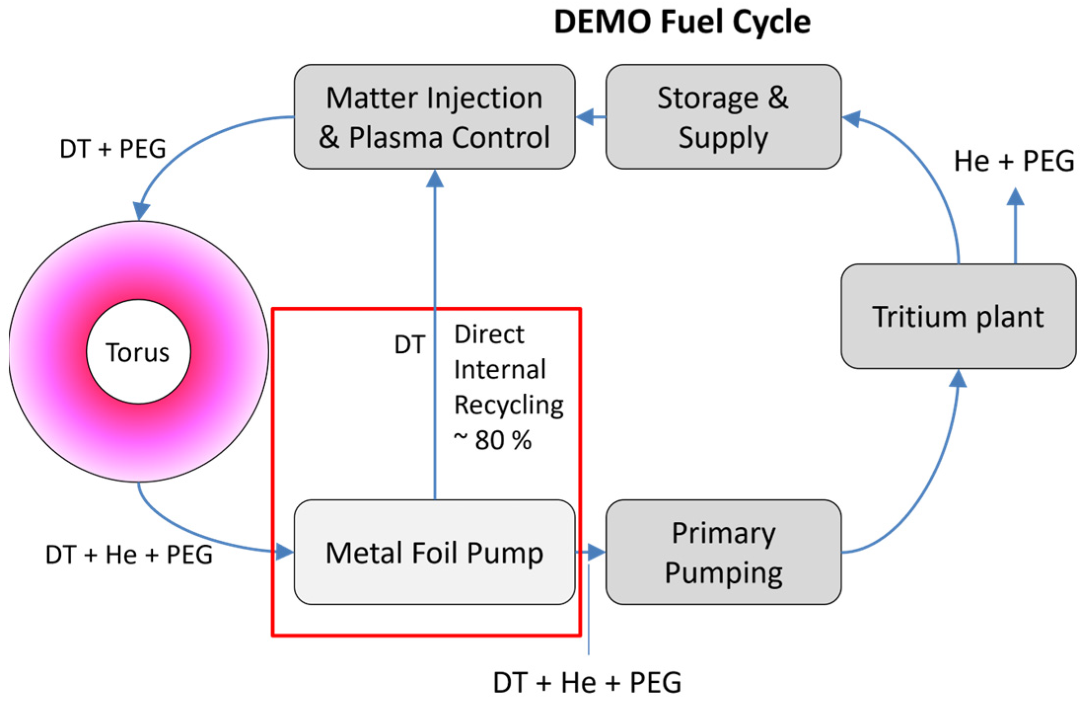
:1. Introduction
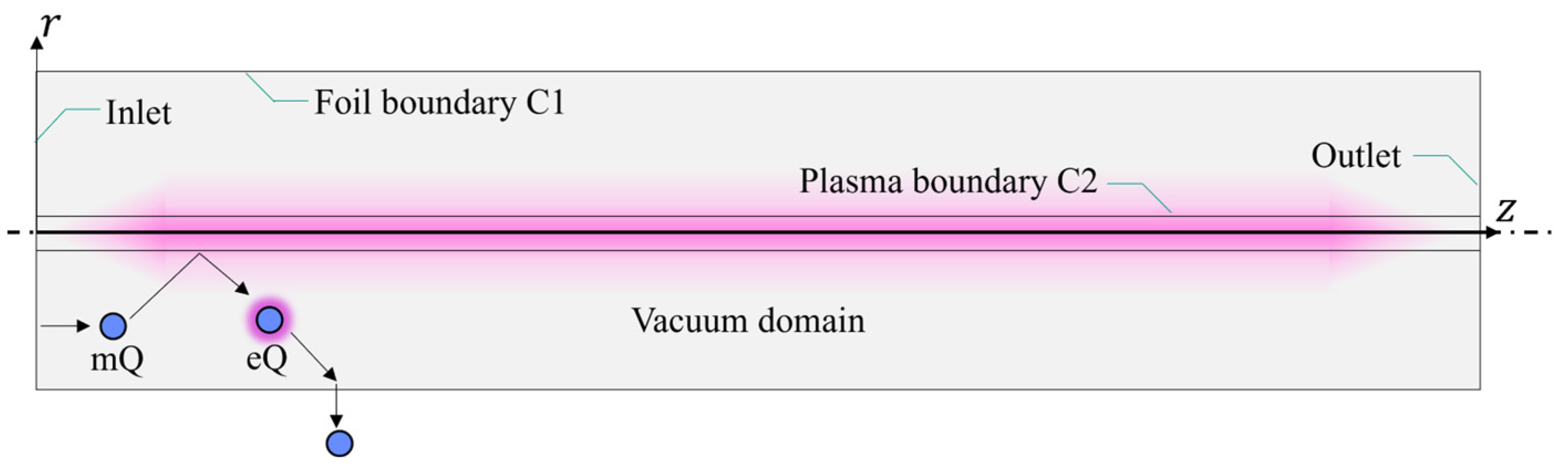
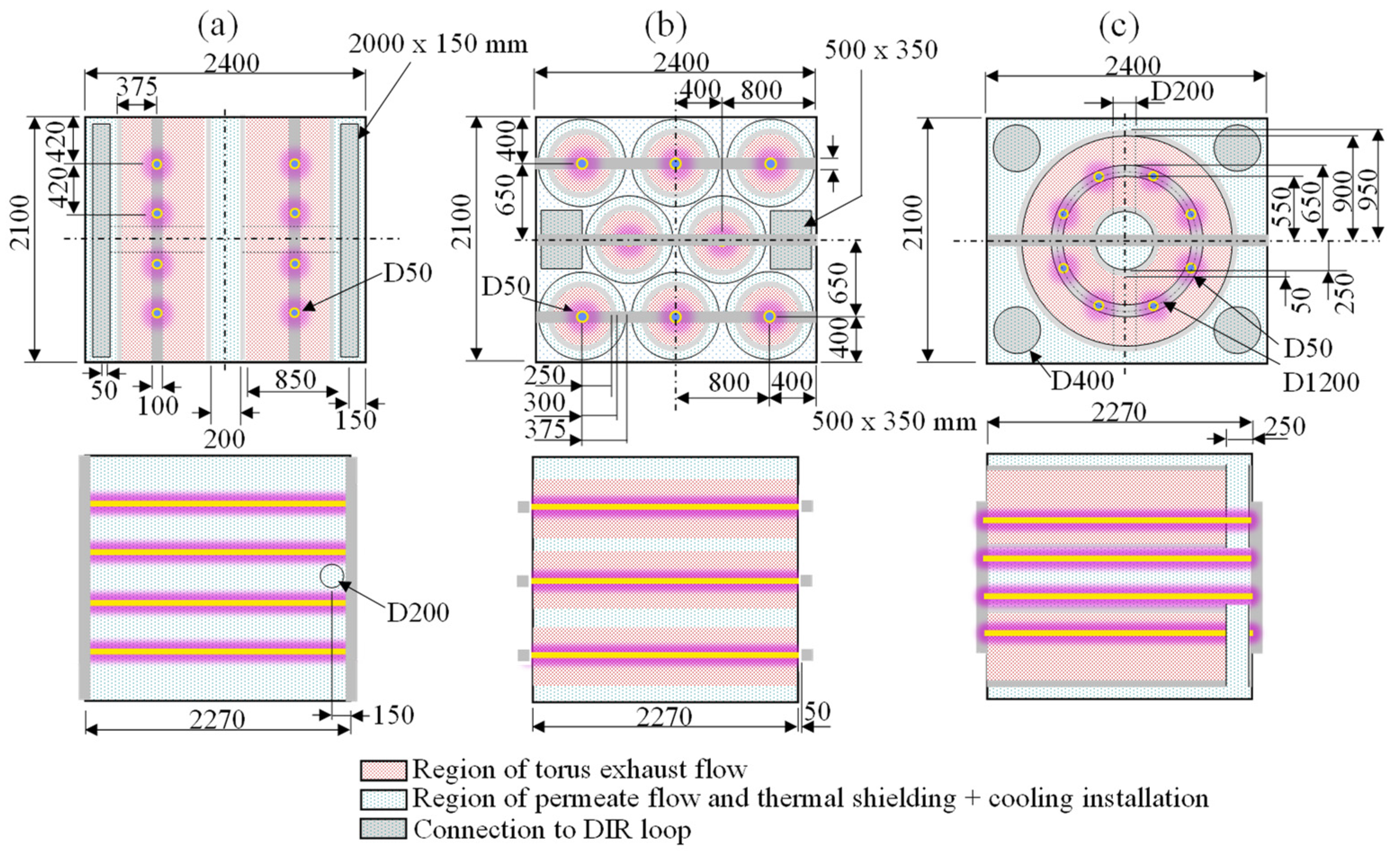
2. MFP Working Principle and Simulation Model
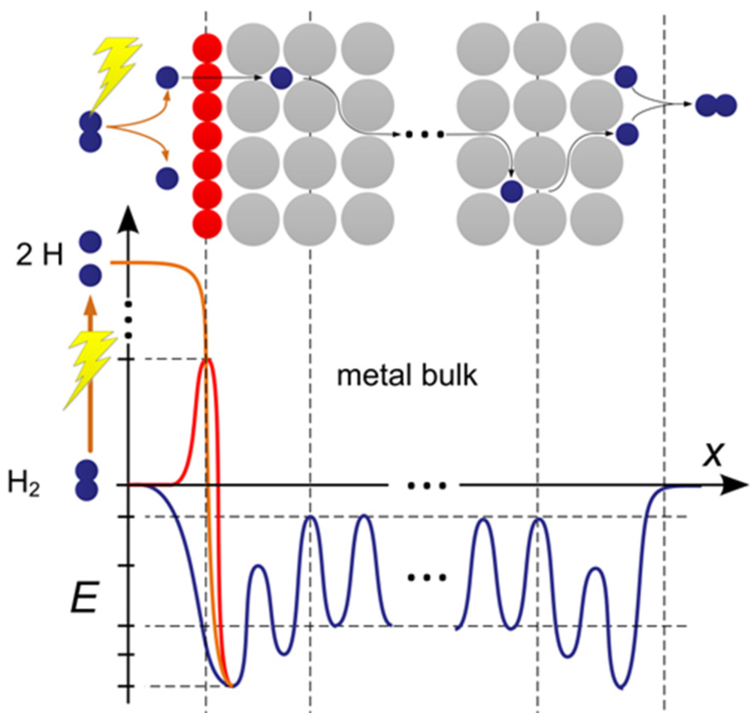
- When hydrogen molecules enter the MFP inlet as mQ, they can be excited to eQ at the temperature of the plasma source and the excitation probability is c2e; the residual of mQ (1 − c2e) will reflect as mQ without temperature change.
- eQ will reflect on the plasma boundary at the temperature of the plasma source. However, eQ can recombine into mQ at a recombination probability of c2er = 0.02 [16].
- The permeation probability of eQ is c1e, and the residual of eQ (1 − c1e) will reflect at the temperature of the metal foil, in which eQ is possible to recombine into mQ and the recombination probability is taken as c1r = c1e.
- All ground-state particles mQ are reflected as such and take on the temperature of the metal foil upon collision with it.
3. Helium Transmission Probability
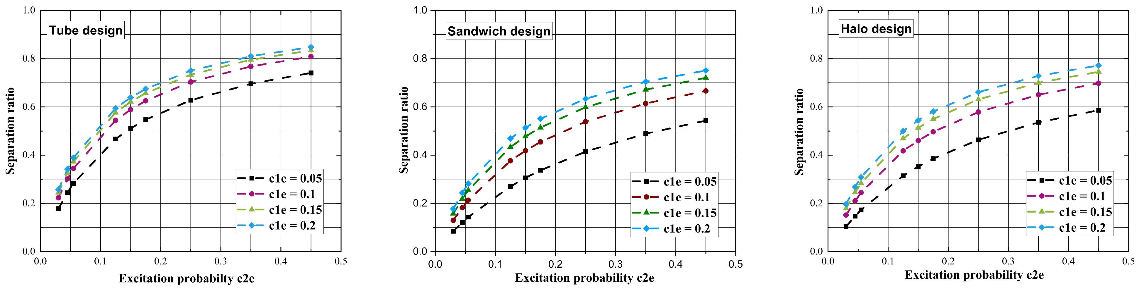
4. Deuterium Pumping Speed and Separation Factor
5. Sensitivity Study of Geometrical and Physical Parameters in the Sandwich Design
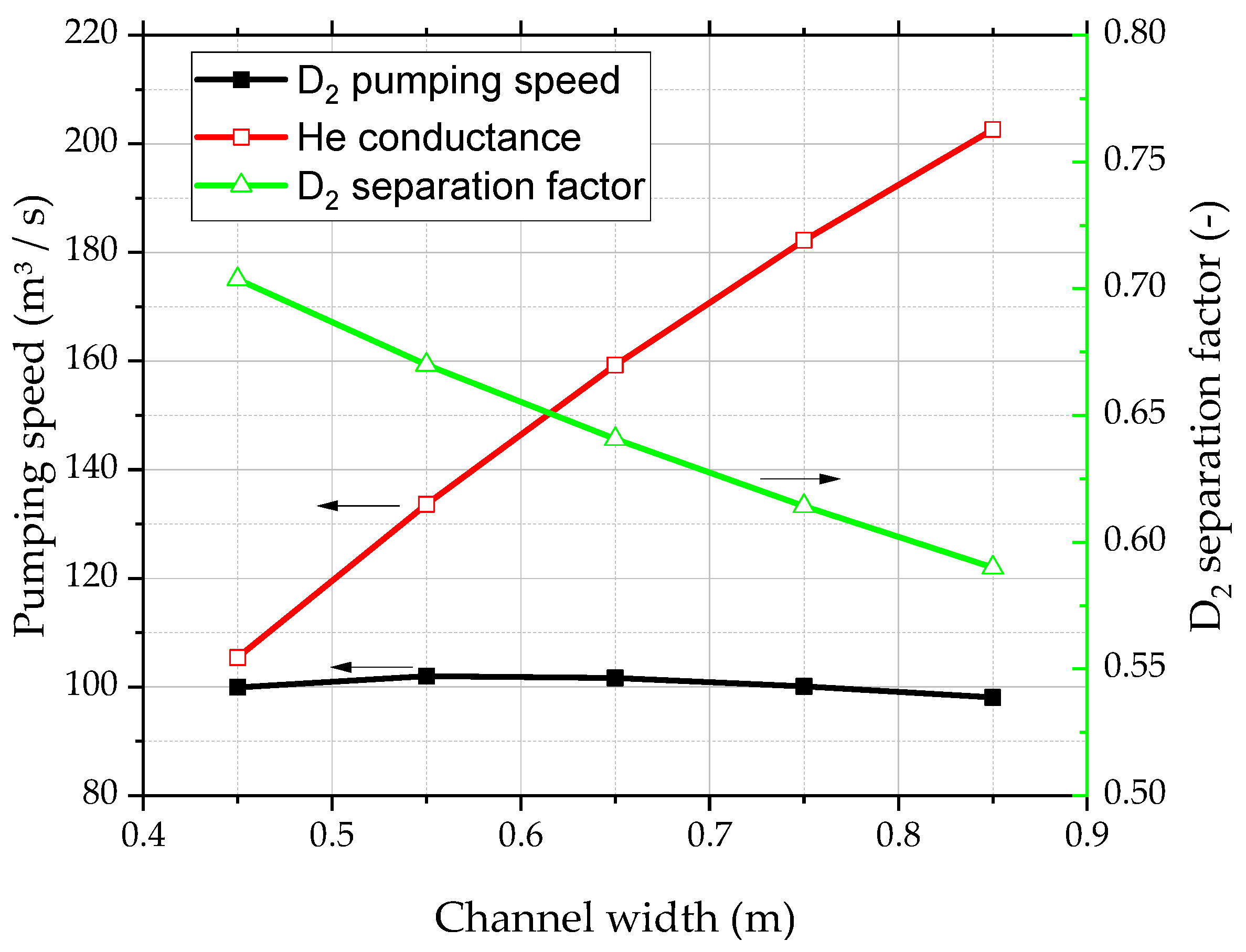
5.1. Channel Width
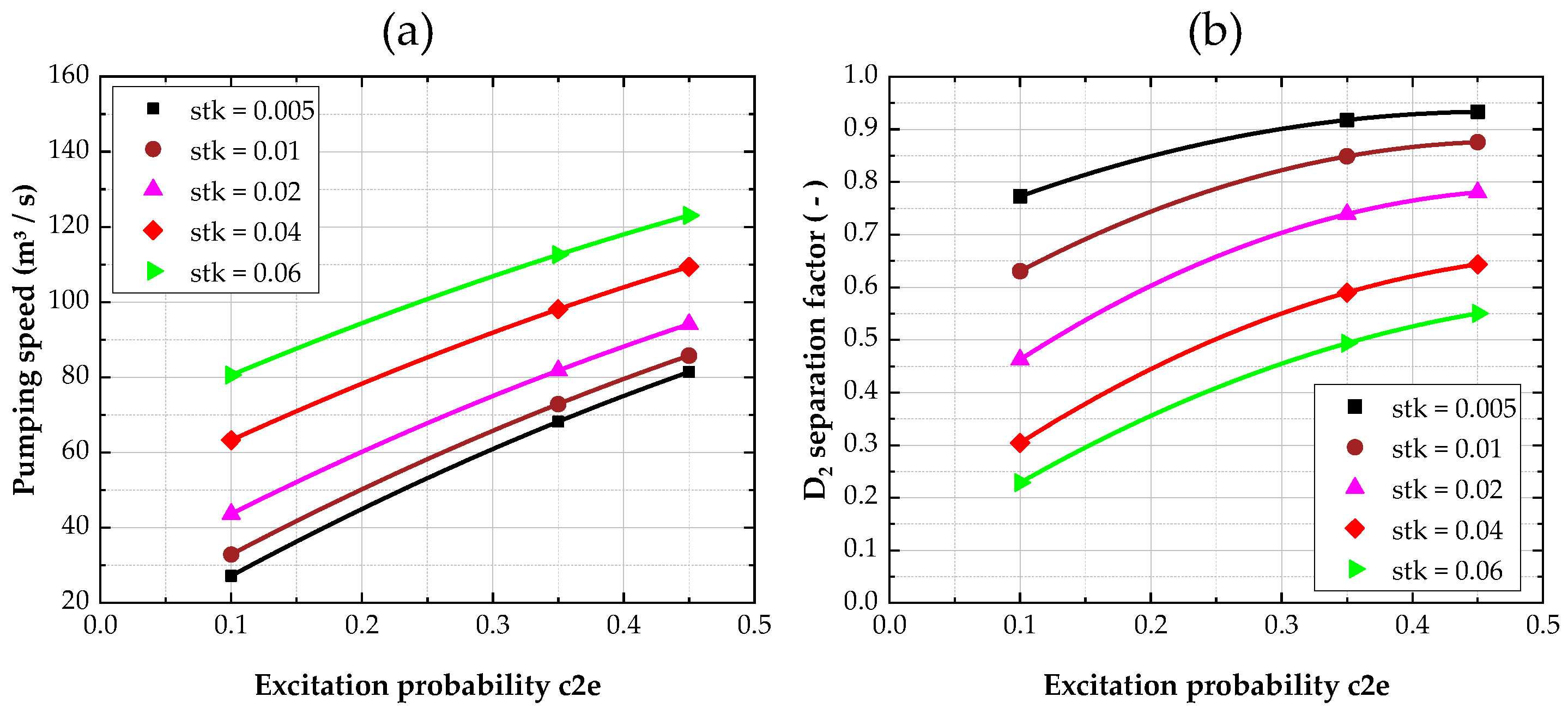
5.2. Sticking Coefficient (stk) of the System Outlet
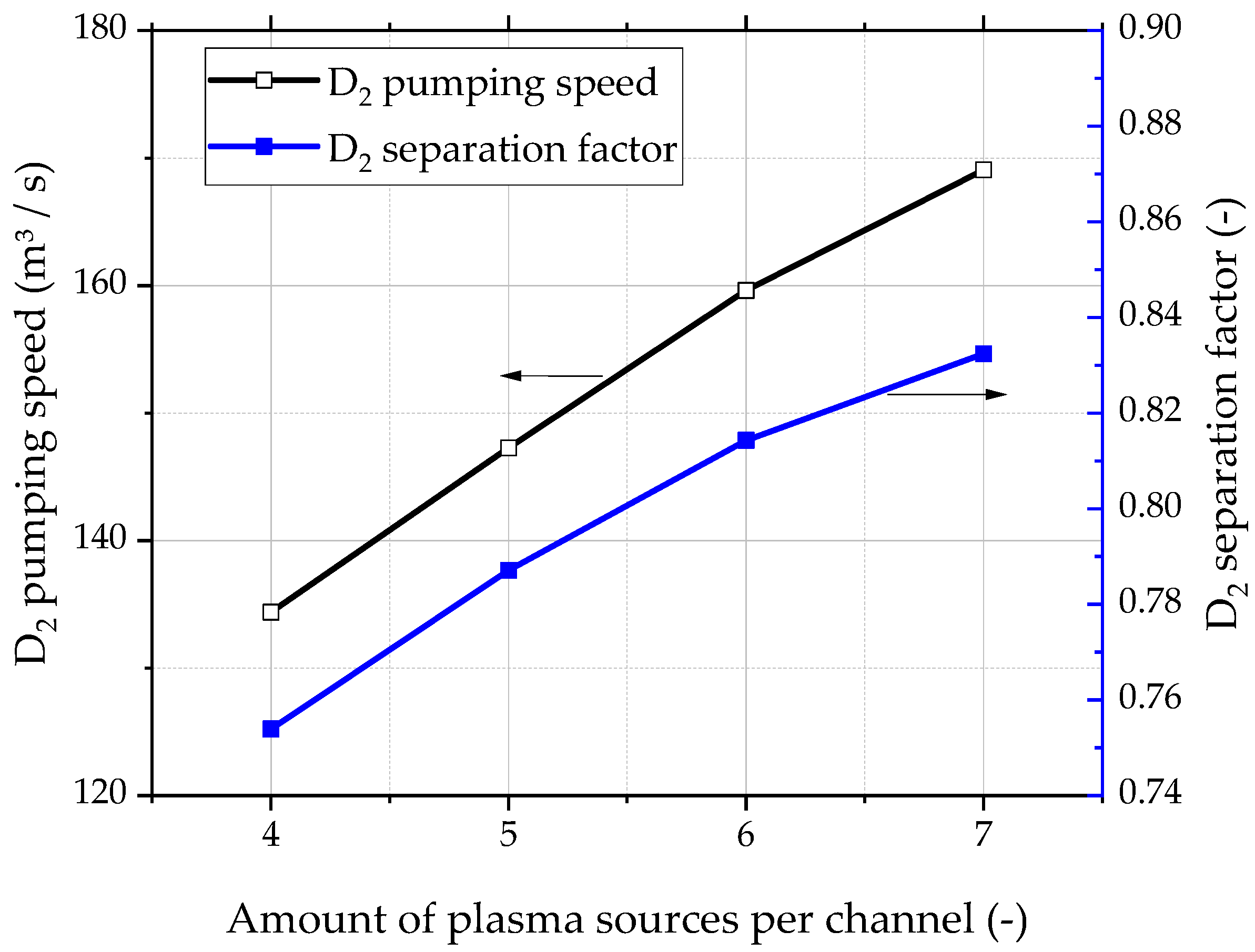
5.3. Number of Plasma Sources in One Channel
5.4. Configuration with Three Channels
6. Conclusions
Author Contributions
Funding
Data Availability Statement
Acknowledgments
Conflicts of Interest
References
- Biel, W.; Backers, M.; Kemp, R.; Wenninger, R.; Zohm, H. Systems code studies on the optimization of design parameters for a pulsed DEMO tokamak reactor. Fusion Eng. Des. 2017, 123, 206–211. [Google Scholar] [CrossRef]
- Federici, G.; Bachmann, C.; Barucca, L.; Biel, W.; Boccaccini, L.; Brown, R.; Bustreo, C.; Ciattaglia, S.; Cismondi, F.; Coleman, M.; et al. DEMO design activity in Europe: Progress and updates. Fusion Eng. Des. 2018, 136, 729–741. [Google Scholar] [CrossRef]
- Day, C.; Giegerich, T. The Direct Internal Recycling concept to simplify the fuel cycle of a fusion power plant. Fusion Eng. Des. 2013, 88, 616–670. [Google Scholar] [CrossRef]
- Peters, B.J.; Hanke, S.; Day, C. Metal Foil Pump performance aspects in view of the implementation of Direct Internal Recycling for future fusion fuel cycles. Fusion Eng. Des. 2018, 136, 1467–1471. [Google Scholar] [CrossRef]
- Hanke, S.; Day, C.; Giegerich, T.; Igitkhanov, J.; Kathage, Y.; Luo, X.; Varoutis, S.; Cortes, A.V.; Härtl, T.; Busniuk, A.; et al. Progress of the R&D programme to develop a metal foil pump for DEMO. Fusion Eng. Des. 2020, 161, 111890. [Google Scholar]
- Li, C.; Fuerst, T.F.; Way, J.D.; Wolden, C. Low temperature hydrogen superpermeation in vanadium composite metal foil pumps. Nuclear Mater. Energy 2023, 37, 101529. [Google Scholar] [CrossRef]
- Giegerich, T.; Day, C.; Gliss, C.; Luo, X.; Strobel, H.; Wilde, A.; Jimenez, S. Preliminary configuration of the torus vacuum pumping system installed in the DEMO lower port. Fusion Eng. Des. 2019, 146, 2180–2183. [Google Scholar] [CrossRef]
- You, J.H.; Mazzone, G.; Visca, E.; Greuner, H.; Fursdon, M.; Addab, Y.; Bachmann, C.; Barrett, T.; Bonavolontà, U.; Böswirth, B.; et al. Divertor of the European DEMO: Engineering and technologies for power exhaust. Fusion Eng. Des. 2022, 175, 113010. [Google Scholar] [CrossRef]
- Day, C.; Battes, K.; Butler, B.; Davies, S.; Farina, L.; Frattolillo, A.; George, R.; Giegerich, T.; Hanke, S.; Härtl, T.; et al. The pre-concept design of the DEMO tritium, matter injection and vacuum systems. Fusion Eng. Des. 2022, 179, 113129. [Google Scholar] [CrossRef]
- Teichmann, T.; Luo, X.; Giegerich, T.; Day, C. Study of the effective torus exhaust high vacuum pumping system performance in the inner tritium plant loop of EU-DEMO. Fusion Sci. Technol. 2024, 80, 399–410. [Google Scholar] [CrossRef]
- Jousten, K. (Ed.) Chapter 5. Analytical and Numerical Calculations of Rarefied Gas Flows. In Handbook of Vacuum Technology, 2nd ed.; Wiley-VCH: Weinheim, Germany, 2016; ISBN 978-3-527-41338-6. [Google Scholar]
- Livshits, A.I.; Notkin, M.E.; Samartsev, A.A. Physico-chemical origin of superpermeability—Large-scale effects of surface chemistry on “hot” hydrogen permeation and absorption in metals. J. Nuclear Mater. 1990, 170, 79–94. [Google Scholar] [CrossRef]
- Hatano, Y.; Watanabe, K.; Livshits, A.; Busnyuk, A.; Alimov, V.; Nakamura, Y.; Hashizume, K.-I. Effects of bulk impurity concentration on the reactivity of metal surface: Sticking of hydrogen molecules and atoms to polycrystalline Nb containing oxygen. J. Chem. Phys. 2007, 127, 204707. [Google Scholar] [CrossRef] [PubMed]
- Luo, X.; Hauer, V.; Day, C. Monte Carlo calculation of the thermal radiation heat load of the ITER pre-production cryopump. Fusion Eng. Des. 2012, 87, 603–607. [Google Scholar] [CrossRef]
- Luo, X.; Scannapiego, M.; Day, C.; Sakurai, S. Assessment of the JT-60SA divertor cryopump performance. Fusion Eng. Des. 2018, 136, 467–471. [Google Scholar] [CrossRef]
- St-Onge, L.; Moisan, M. Hydrogen atom yield in RF and microwave hydrogen discharges. Plasma Chem. Plasma Process. 1994, 14, 87–116. [Google Scholar] [CrossRef]
- Luo, X.; Day, C. Topological impact of a simple self-replication geometric structure with great application potential in vacuum pumping and photovoltaic industry. J. Vac. Sci. Technol. B 2021, 39, 054203. [Google Scholar] [CrossRef]


| Design | Total MF Area (m2) | Total MFP Inlet Area (m2) | w | Conductance (m3/s) |
|---|---|---|---|---|
| Sandwich | 19.07 | 3.15 | 0.104 | 182.25 |
| 8-tube | 28.53 | 1.56 | 0.040 | 70.26 |
| Halo | 17.12 | 2.26 | 0.081 | 140.89 |
| 8-Tube Design | Sandwich Design | Halo Design | ||||||||||
|---|---|---|---|---|---|---|---|---|---|---|---|---|
| S(m3/s) | c1e = 0.05 | c1e = 0.1 | c1e = 0.15 | c1e = 0.2 | c1e = 0.05 | c1e = 0.1 | c1e = 0.15 | c1e = 0.2 | c1e = 0.05 | c1e = 0.1 | c1e = 0.15 | c1e = 0.2 |
| c2e = 0.03 | 41.04 | 42.87 | 43.79 | 44.34 | 48.73 | 50.96 | 52.46 | 53.54 | 47.05 | 49.29 | 50.68 | 51.63 |
| c2e = 0.045 | 43.80 | 46.46 | 47.79 | 48.59 | 50.51 | 53.81 | 56.02 | 57.61 | 49.09 | 52.38 | 54.42 | 55.80 |
| c2e = 0.055 | 45.56 | 48.75 | 50.34 | 51.30 | 51.68 | 55.67 | 58.35 | 60.27 | 50.41 | 54.38 | 56.84 | 58.51 |
| c2e = 0.125 | 56.56 | 62.92 | 66.06 | 67.96 | 59.43 | 67.96 | 73.62 | 77.65 | 58.96 | 67.27 | 72.35 | 75.79 |
| c2e = 0.15 | 59.99 | 67.31 | 70.90 | 73.08 | 62.03 | 72.05 | 78.67 | 83.38 | 61.75 | 71.45 | 77.35 | 81.34 |
| c2e = 0.175 | 63.20 | 71.39 | 75.41 | 77.84 | 64.54 | 75.99 | 83.53 | 88.88 | 64.42 | 75.42 | 82.10 | 86.61 |
| c2e = 0.25 | 71.70 | 82.16 | 87.25 | 90.32 | 71.64 | 87.03 | 97.08 | 104.16 | 71.75 | 86.28 | 95.03 | 100.90 |
| c2e = 0.35 | 80.96 | 93.79 | 100.01 | 103.75 | 80.16 | 100.13 | 113.03 | 122.06 | 80.22 | 98.68 | 109.71 | 117.07 |
| c2e = 0.45 | 88.50 | 103.19 | 110.29 | 114.56 | 87.76 | 111.68 | 126.99 | 137.64 | 87.48 | 109.20 | 122.10 | 130.66 |
| 8-Tube Design | Sandwich Design | Halo Design | ||||||||||
|---|---|---|---|---|---|---|---|---|---|---|---|---|
| P | c1e = 0.05 | c1e = 0.1 | c1e = 0.15 | c1e = 0.2 | c1e = 0.05 | c1e = 0.1 | c1e = 0.15 | c1e = 0.2 | c1e = 0.05 | c1e = 0.1 | c1e = 0.15 | c1e = 0.2 |
| c2e = 0.03 | 0.178 | 0.223 | 0.244 | 0.257 | 0.084 | 0.129 | 0.158 | 0.177 | 0.104 | 0.151 | 0.179 | 0.196 |
| c2e = 0.045 | 0.245 | 0.301 | 0.327 | 0.342 | 0.121 | 0.182 | 0.219 | 0.244 | 0.147 | 0.210 | 0.245 | 0.268 |
| c2e = 0.055 | 0.283 | 0.345 | 0.373 | 0.389 | 0.143 | 0.213 | 0.255 | 0.282 | 0.173 | 0.245 | 0.284 | 0.308 |
| c2e = 0.125 | 0.467 | 0.544 | 0.576 | 0.595 | 0.270 | 0.376 | 0.433 | 0.469 | 0.315 | 0.418 | 0.469 | 0.500 |
| c2e = 0.15 | 0.511 | 0.589 | 0.621 | 0.639 | 0.306 | 0.419 | 0.477 | 0.513 | 0.352 | 0.461 | 0.513 | 0.544 |
| c2e = 0.175 | 0.547 | 0.625 | 0.657 | 0.675 | 0.337 | 0.455 | 0.515 | 0.551 | 0.385 | 0.497 | 0.550 | 0.581 |
| c2e = 0.25 | 0.628 | 0.704 | 0.734 | 0.750 | 0.414 | 0.539 | 0.598 | 0.634 | 0.463 | 0.579 | 0.631 | 0.661 |
| c2e = 0.35 | 0.696 | 0.768 | 0.796 | 0.810 | 0.489 | 0.614 | 0.672 | 0.704 | 0.536 | 0.650 | 0.700 | 0.728 |
| c2e = 0.45 | 0.741 | 0.809 | 0.834 | 0.848 | 0.543 | 0.666 | 0.720 | 0.751 | 0.586 | 0.698 | 0.746 | 0.772 |
| M | Pumping Speed S (m3/s) | Separation Ratio P |
|---|---|---|
| 4 | 98.09 | 0.5900 |
| 5 | 107.37 | 0.6353 |
| 6 | 116.91 | 0.6746 |
| 7 | 124.62 | 0.7019 |
| 8 | 132.43 | 0.7264 |
Disclaimer/Publisher’s Note: The statements, opinions and data contained in all publications are solely those of the individual author(s) and contributor(s) and not of MDPI and/or the editor(s). MDPI and/or the editor(s) disclaim responsibility for any injury to people or property resulting from any ideas, methods, instructions or products referred to in the content. |
© 2024 by the authors. Licensee MDPI, Basel, Switzerland. This article is an open access article distributed under the terms and conditions of the Creative Commons Attribution (CC BY) license (https://creativecommons.org/licenses/by/4.0/).
Share and Cite
Luo, X.; Kathage, Y.; Teichmann, T.; Hanke, S.; Giegerich, T.; Day, C. Assessment of Metal Foil Pump Configurations for EU-DEMO. Energies 2024, 17, 3889. https://doi.org/10.3390/en17163889
Luo X, Kathage Y, Teichmann T, Hanke S, Giegerich T, Day C. Assessment of Metal Foil Pump Configurations for EU-DEMO. Energies. 2024; 17(16):3889. https://doi.org/10.3390/en17163889
Chicago/Turabian StyleLuo, Xueli, Yannick Kathage, Tim Teichmann, Stefan Hanke, Thomas Giegerich, and Christian Day. 2024. "Assessment of Metal Foil Pump Configurations for EU-DEMO" Energies 17, no. 16: 3889. https://doi.org/10.3390/en17163889