Abstract
This article proposes the use of a three-phase induction generator (IG), connected through a single-phase connection (Fukami configuration), to be used as a rotating exciter for synchronous generators. This proposal aims at presenting an alternative to replace the permanent magnet generators (PMGs) used in the rotating exciters for synchronous generators (SGs). In order to obtain the results, a six-pole IG and a four-pole SG were used, a DC motor (DCM) was employed as the primary machine, and the speed control for the aforementioned primary machine is presented and described in this work. To carry out performance tests of the rotating exciter with the IG and the terminal voltage control of the SG, a voltage controller was proposed. The performance of the voltage regulator was tested when the SG supplied a dynamic load, as established by the NEMA MG-1 standard. This article validates its proposal by comparing the results obtained through computational simulation and experimental testing of the SG terminal voltage waveform when faced with a sudden load change.
1. Introduction
The electrical energy scenario in Brazil and around the world uses, in greater part, synchronous machines. This is due to the fact that this form of generation can be easily put into operation in parallel with an electrical power system [1,2].
The abovementioned scenario appears in many countries, where these generators are interconnected by transmission lines [3] and driven by various primary source means, such as hydraulic, gas, wind, and others.
These generators are not restricted only to use in large distribution systems; these are also found in isolated systems, along with areas of difficult access, where costs can be very high for the interconnection of transmission lines, with use being made principally of diesel generator sets (DGSs). These generator sets can also play a role as an emergency unit to supply energy to industries, hospitals, shopping malls, and convention centers, among others [2,3,4].
In the synchronous generator, the generated voltage is regulated by varying the continuous field current supplied in the field winding on the rotor. This is known as an excitation system, and when combined with a control system, it regulates the voltage and reactive power on the armature terminals.
Currently, one of the most widely used systems, by DGS manufacturers, for high-performance requirements, in the control of excitation, is the use of a permanent magnet generator (PMG). This generator is connected to the main generator shaft and, together with an automatic voltage regulator (AVR), ensures the necessary field current for the generator [5].
The PMG, as noted in [5,6], presents a series of benefits for the DGS. However, besides the presented benefits, nowadays, the subject of environmental impact must also be considered, as the magnets used in PMGs are produced with rare earth elements, mainly neodymium iron boron (NdFeB). This presents challenges regarding the manufacturing process in relation to the environment; moreover, consideration also needs to be given to that presented in [7,8] regarding the uncertainty of the price, monopoly, and depletion of this material.
The squirrel cage induction machine (IM) aroused interest in the scientific and industrial communities for applications in actuators or generation systems. This interest is due to its robust nature, constructively simple design, low maintenance, high power density, and low cost [9,10].
However, self-excited induction generators (SEIGs) suffer from unsatisfactory voltage regulation and frequency variations and are therefore only suitable for fixed-speed applications [11,12].
Another way to use SEIGs is described in [13], which is the use of a three-phase induction generator, with an advanced degree of phase symmetrization, which can be a practical solution for single-phase output, at least above 2 to 3 kW per unit. Three of the main connections are hereby proposed—Steinmetz [14,15], Smith [16,17], and Fukami [15,18,19]. Other works present studies that demonstrate configuration variations that demonstrate a good applicability for this way of using IG in single-phase configuration [20,21,22,23,24,25,26,27].
The Fukami configuration for a self-excited induction generator, with the capacitor set in the single-phase configuration, consists of a squirrel cage IM and three capacitors. The three capacitors are externally connected in a series parallel with the stator winding of the induction machine to supply electrical power to a single-phase load. This can provide a self-regulation feature, as well as self-excitation, with stability in the excitation power system [18].
Given these characteristics, this work proposes the use of the Fukami configuration in an unconventional rotating exciter topology to replace the PGM exciter used in the DGS, with the aim of presenting the advantages concerning the use of this topology. The performance of this exciter will be tested through the SG that will be subjected to dynamic and resistive loads, and the results to validate the proposal will be achieved by comparing the experimental and computational results.
Next, Section 2 describes the approach used to develop the proposal of this article, where the methodology used in the proposed system is presented. Section 3 presents the IG operating principle. Section 4 presents the description of the computational simulation and experimental test. Section 5 presents the results and discussions, in which the proposal of the article is validated. Finally, Section 6 presents the conclusions for this work.
2. Proposed System
Figure 1 presents the circuit diagram used for the computational simulations and experimental tests. A primary machine is used in this system, represented by a 2 kW DCM, actuated by a speed controller to maintain the reference speed at 1800 rpm. The IG, connected to the axis of the primary machine, possesses a power of 0.37 kW, 6 poles connected in with capacitors connected to its terminals in the Fukami configuration, to generate self-excitation of the machine in the single-phase configuration. The SG also connected to the primary machine shaft is 3 kVA, connected in with a phase-to-phase voltage of 220 V rms.
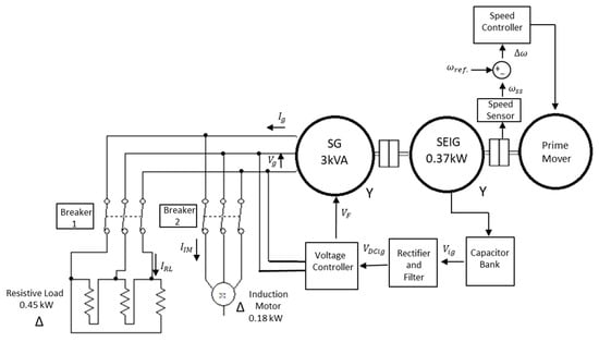
Figure 1.
Electrical and block diagram of the proposed system.
The load used is activated individually, that being a three-phase 0.45 kW resistive load connected to and a 0.18 kW IM connected to In this arrangement, both are used to test the behavior of the SG regarding the proposed exciter, which is presented in conjunction with its speed and voltage controls, to verify its efficiency.
2.1. Induction Generator
The IG with a squirrel cage rotor is an excitation system that uses a bank of capacitors connected at its terminals. The moment the generator reaches the appropriate speed, the residual magnetism, present in its field circuit, produces a small voltage that it applies to the capacitor bank and performs self-excitation. However, as presented in [28], the power supplied by the IG depends on the speed of the primary machine that works at 1800 rpm, which is the synchronous speed of the SG. Therefore, if one chooses a 6-pole machine to avoid problems with the power supplied by the IG, this generator will operate at a speed above its nominal speed of 1200 rpm.
When connecting the capacitors, the configuration presented in [18] was used; this went on to make up the IG, according to the characteristics that are also presented in [18]. This generated voltage will be used after rectification to power the SG exciter. The determination of the values for the capacitors used by the IG is presented in Appendix B.
The mathematical model for analyzing the IG behavior in computer simulations is presented in [29], where the circuit is understood in its arbitrary reference . The mechanical and electrical equations are presented in Appendix A.
The magnetizing reactance of IG has non-linear behavior, and the parameterization of the computational model to represent this behavior uses the magnetization curve of the generator. This curve is obtained through laboratory tests, as demonstrated in [28,30] and presented in Figure A1 in Appendix A.
2.2. Synchronous Generator
In the SG, the electrical frequency produced is synchronized or linked to the mechanical rotation speed of the generator [31]. The generator rotor forms an electromagnet when a direct current (DC) voltage is applied to its winding.
The SG used in the system has a salient pole rotor, with damper windings.
Through field current control , automatically adjusted by the generator control system, one obtains armature voltage control, which is the generator voltage . As such, synchronous speed is maintained through the speed control of the primary machine.
The mathematical model used in the computational model to represent SG behavior was presented in [29], where its circuit was understood to be in its arbitrary frame of reference . The electrical equations and mechanics of the synchronous machine are presented in Appendix A.
2.3. Speed Control
The block diagram of the speed control circuit is shown in Figure 2, and this acts on the primary machine, which is composed of a 2 kW DCM.
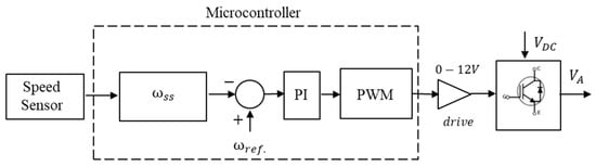
Figure 2.
Diagram of the primary machine speed control system block.
The field winding is supplied with a constant voltage of 220 VDC. For speed control, the armature winding is supplied by a switching circuit with insulated gate bipolar transistors (IGBTs) (FGH60N60) with a DC source of 350 VDC. The actuation is performed by a drive that uses a TIP 31 to amplify the level of pulse width modulation (PWM) of the 3.3 VDC microcontroller output for the control at 12 VDC.
To sample the signal for the PWM control, a Hall sensor was used to measure rotations with magnets coupled to the DCM axis. This generates pulses that are used as a time base, and these are then delivered to the ESP32 microcontroller. In this microcontroller, through an analog input, this signal is converted to a digital signal that is handled by the ESP32 through its 12-bit DAC (digital analog converter). In this way, a vector is created for the analysis of a set of samples, which is the speed sensor sample . This will then be compared with a reference value, which is sampled through tests at the 1800 rpm reference , while keeping the generation frequency at 60 Hz. The sampled and compared values go through a proportional integral controller (PI), and in this signal, a duty cycle between 60% and 85% is defined, which, through tests, proved to be efficient in terms of generation levels according to load limits. Within this range, PWM is generated at the ESP32 output that uses the drive to raise this voltage level, which is then delivered to the IGBT. Therefore, every time there is a load change in the system, the speed control will increase or decrease the PWM switching to maintain a constant rotation. The gains used in the PI controller are Kp = 0.4 and Ki = 0.2. The bench-mounted speed controller is shown in Figure 3.
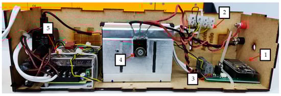
Figure 3.
Assembled circuit of the speed controller: 1—microcontroller ESP32, 2—speed sensor signal, 3—drive, 4—IGBT: FGH60N60, and 5—source for the microcontroller.
2.4. Voltage Control
The voltage control for the generation system is shown in Figure 4. This system is composed of an instrumentation circuit that attenuates the line voltage from 310 VAC to 1.3 VAC and a low-pass filter (LPF) to eliminate noise, and this value is delivered to an analog input of an ESP32 microcontroller. This sampled signal is converted through the 12-bit DAC of the microcontroller, creating a vector of samples for comparison with a reference value that is sampled through testing. This sample represents the control value, which is the generated reference voltage of 220 Vrms (line voltage). This signal is defined in a duty cycle between 50% and 80%, which, through testing, proved to be efficient in terms of generation levels, depending on load limits. After comparing the sampled voltage signals, a PI controller situated in the microcontroller is used to respond to and maintain the generator output voltage constant at the reference value. The PWM signal generated by the controller is sent to an optocoupler that feeds into a drive, which raises the voltage value in order to activate the IGBT. Therefore, the voltage of the field winding of the SG is controlled and, as such, maintains the voltage constant. The IGBT (FGH60N60) receives the rectified voltage supplied by the IG. The gains used in the PI controller are Kp = 0.5 and Ki = 1.2. The bench-mounted voltage controller is shown in Figure 5.
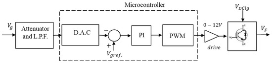
Figure 4.
Block diagram of the SG voltage control system.
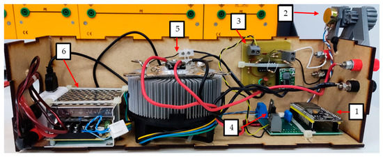
Figure 5.
Assembled voltage controller circuit: 1—microcontroller ESP32, 2—setpoint adjustment, 3—attenuator and LPF, 4—drive, 5—IGBT: FGH60N60, and 6—source for the microcontroller.
3. Operating Principle
Figure 6 presents the connection diagram of the self-excited configuration of the three-phase induction generator in the Fukami single-phase configuration (dashed in blue in the figure). This is interconnected to a rectification and filtering system, which supplies the single-phase representation of the synchronous generator (dashed in red in the same figure).
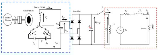
Figure 6.
Circuit representing the IG with rectification and filtering and the equivalent circuit per phase of the SG (adapted from [18]).
In Figure 6, the elements of the electrical circuit of the induction generator in the Fukami connection are represented by the following elements—the currents that exit the phases. Here, represents the current of winding , the current on winding , and the current on winding . Point is the reference of the system in , and the capacitors are in the series with the windings and . On the central point between the capacitors the new reference will be established from the single-phase configuration, which is . In parallel with the capacitor , a rectification and filtering system will be interconnected to supply the excitation system proposed in this work. In accordance with that demonstrated in [18], the output voltage is demonstrated through the vectorial sum of the phase voltage and the voltage is demonstrated through the terminals .
The current is the vectorial representation of the current that circulates on winding , and is the vectorial representation of the interaction of the two phase currents and with capacitor . As such, according to [18], the output voltage can be expressed in the form of
where
Substituting Equation (2) into (1) shows
By calculating Equation (3), one obtains the vector expression of
where and is the output frequency, is the phase voltage on winding , and voltage is the line voltage between windings and .
The generated voltage will be delivered to the rectifier circuit, generating a constant DC voltage . Giving further analysis to Figure 6, the switch represents the switching circuit of the voltage control. The current is delivered to the field winding on the rotor that will generate a voltage , and and are the reactance and resistance of the SG stator. When feeding a load, a current will circulate in the circuit and will cause a voltage drop in the elements and and the phase terminal voltage in the load . With greater or lesser demand from the load, the current will vary, requiring more excitation of the field that is controlled by the switch . Therefore, the IG, which supplies the excitation system, must guarantee the current required by the generation system.
4. Description of the Computer Simulation and Experimental Test
Computational simulations and experimental tests are carried out for the circuit in Figure 1, which is a diagram with a generation system to simulate a DGS with an exciter using an IG. As described in the previous section, which uses a 0.37 kW IM with 6 poles connected in ), with its data presented in Table A2 in Appendix B, this motor, together with the capacitors, which have their values presented in Table A3 in Appendix B, connected in the configuration presented in Figure 6, generate a single-phase output voltage in a root mean square (RMS) single phase. This generated voltage is rectified by the diode bridge and filtered through a capacitor of 212 , where it is transformed into a direct current voltage; this DC voltage with switch Breaker 3 is used to excite the SG field.
The SG uses a synchronous machine of 3 kVA with salient poles and with a field winding on the rotor, using slip rings and brushes for power, together with its armature connected in ) with a line voltage of 220 V rms, with its data presented on Table A4, Appendix B.
The DC voltage delivered to the SG field winding needs to be controlled to maintain the generation voltage constant. Therefore, a voltage controller is used that is based on the configuration of the diagram presented in Figure 4 and explained in Section 2.4.
The armature winding of the SG, connected in , is interconnected to the loads providing a line voltage of 220 V rms. As the phase voltages of the loads are 220 V rms, they were connected to the delta connection .
For the loads, a resistive load consisting of 3 lamps with a total three-phase power of 0.450 kW connected in and a dynamic load represented by an IM are used. This is a more critical load, since, in direct starting, a three-phase induction motor can require a starting power of 6 to 8 times the value of its nominal power [9]. The induction motor is 0.18 kW, and its parameters are presented in Table A5 in Appendix B, with its connection to .
As previously described, both generators are coupled to the same shaft of the primary machine, which ensures that the speed is the same for both machines, with the speed control system maintaining the rotation at 1800 rpm. Therefore, guaranteeing the generation frequency of 60 Hz on the SG and the rotation above the nominal rotation in the IG makes having a self-excitation that generates enough power to excite the SG, in demand of the variable load, necessary.
4.1. Computer Simulation
The circuit in Figure 1 is implemented in a computer model using Simulink R2024a (a toolbox for MATLAB® R2024a software) for a theoretical-to-experimental proof comparison. This is presented in Figure 7.
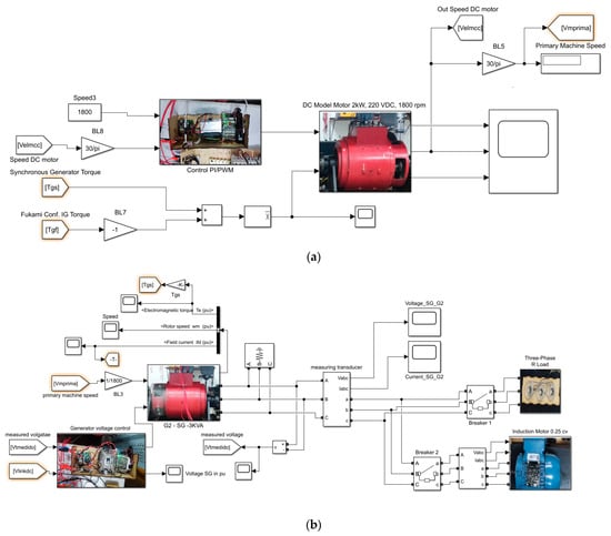
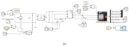
Figure 7.
Diagram used for simulation in MATLAB of the generation system with loads: (a) diagram of the primary machine DCM, (b) diagram of the SG, and (c) diagram of the SEIG.
4.2. Experimental Test
The bench-mounted experimental circuit can be seen in Figure 8, where the direct coupling between the primary machine, the synchronous generator, and the generator in the Fukami connection is presented, which has the role of supplying power to the synchronous generator field circuit. The IG at the Fukami connection has a line voltage of 380 [V rms], and the SG has a nominal line voltage of 220 V rms on the connection. Therefore, to adjust to this voltage feature of the SG, the choice was made to connect the loads in the configuration. This was implemented both for the resistive load using a set of lamps with 0.45 kW three-phase power, and for the dynamic load, which is an IM which power supply in phase-to-phase is 220 V rms, with a power of 0.18 kW. The circuit diagram used is the same as that used in the circuit shown in Figure 1. The procedure for the activation sequence of the elements is the same as that in the simulation.
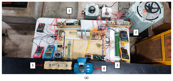
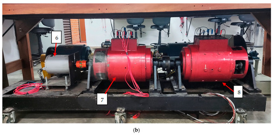
Figure 8.
Experiment set up for testing: (a) 1—speed control, 2—voltage control, 3—IG capacitors, 4—dynamic load, and 5—resistive load; (b) 6—IG, 7—SG, and 8—DCM primary machine.
Therefore, experimental tests were performed to verify the performance of the proposed work. The current and voltage waveforms were recorded by an oscilloscope, and the voltage behavior at the generator terminal in both loads was verified, which could then be used to compare to the simulation values.
5. Results and Discussion
Through use of the experimental test bench, as shown in Figure 8 and in the simulation presented in Figure 7, both assembled in the configuration shown in Figure 1, one obtains the results of the generation voltage and the generation of the current both simulated and experimental, as a function of the resistive load and dynamic load.
In light of these loads, the behavior of the IG in a steady state is demonstrated, supplying the excitation of the SG while presenting the single-phase voltage value and the current along with their respective frequencies , for both the simulated and experimental values. The results are also presented for the behavior of the voltage and current with load insertion. This is performed to verify the active performance with the voltage control, for both simulated and experimental values.
5.1. Results for IG No Load, Simulated, and Experimental Values
Figure 9 shows the results of the single-phase output voltage as an experimental result with a simulated value of 608 V and 567.827 V. Although there is a difference between the values, both results present the expected behavior, demonstrating the effectiveness of the values in relation to the capacitances used in self-excitation at the synchronous speed of 1800 rpm without a load with the capacitance values used from and presented in Table A3 in Appendix B. Figure 10 shows the phase voltage values of the experimental and simulated tests during the IG self-excitation process with the respective specified capacitances.
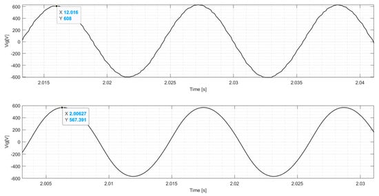
Figure 9.
Single-phase voltage output in the SEIG no load experimental test and simulation.
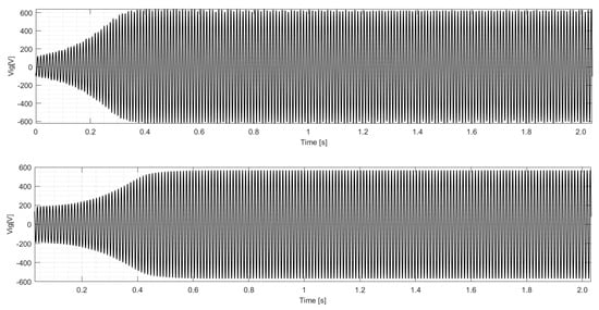
Figure 10.
Voltage buildup in the SEIG experimental test and simulation.
The method used to specify the values of the capacitors used in and is presented in Appendix B.
5.2. Results for SG and IG with IM (Dynamic Load) and Resistive Loads: Simulated and Experimental Values
In Figure 11, the value of the line voltage regime is displayed and line current in the alternating current AC for the SG supplying an IM of 0.18 kW, as previously described connected in with a supply voltage of 220 V rms, and with the SG in a connection that has a line voltage of 220 V rms. One notes in the results that the phase sags due to the load possessing inductive behavior and presenting a harmonic content, which is the same behavior also noted in Figure 12 for both values but, in the simulation, is without harmonic content.
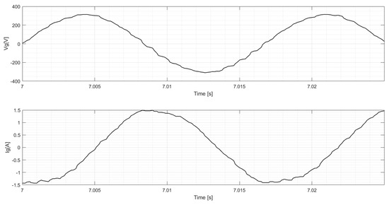
Figure 11.
Line voltage and current and experimental with SG dynamic loading.
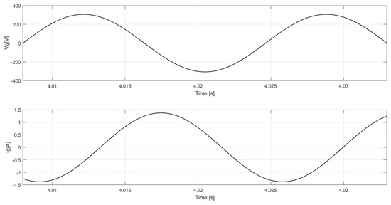
Figure 12.
Line voltage and current and simulated with SG dynamic loading.
Table 1 presents the results for the behavior of the IG that supplies the voltage and current of a steady-state single-phase generation and in the excitation of the SG that supplies the load to the IM. Although there is a difference between the experimental and simulated behavior, the values are still close, thus demonstrating the capacity of the IG to supply the SG excitation power. In addition, the frequency relationship can also be seen as a function of the number of IG poles that present a frequency much higher than that of the SG, but this voltage is transformed into a DC after rectification and filtering as previously mentioned.

Table 1.
Comparison of the results with IM (dynamic load).
Table 2 also presents the SG in the regime supplying the IM load, and the results demonstrate that the IG is able to supply power to maintain the SG supplying the load, while the experimental and simulated results present values close to the SG voltage and current.
Table 2.
Comparison of the results with IM (dynamic load).
In Figure 13, the value is presented for the steady-state line voltage and line current in an AC for the SG, which supplies the three-phase resistive load of 0.45 kW. As previously described, this is connected in with a voltage supply of 220 V rms, and the SG in the connection has a line voltage of 220 V rms. This same phase shift behavior is not seen as a function of the load that possesses resistive behavior and presents harmonic content. This behavior can be seen in Figure 14 for both values but not in the simulation without harmonic content.
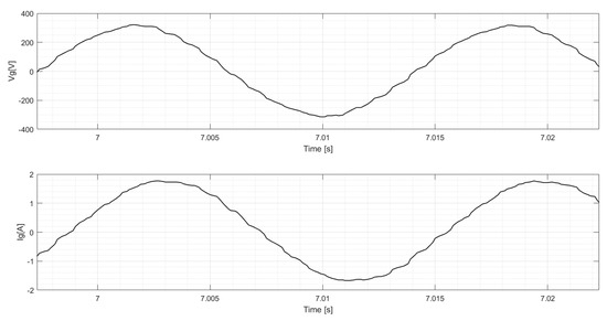
Figure 13.
Line voltage and current and experimental with the SG resistive load.
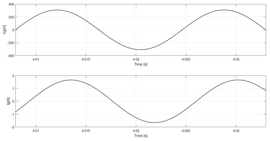
Figure 14.
Line voltage and current and simulated with the SG resistive load.
Table 3 presents the results of the IG behavior, supplying the voltage and current of the single-phase generation regime and in the excitation of the SG that supplies the resistive load. Although there is a difference between the experimental and simulated behavior, the values are close, demonstrating the ability of the IG to provide the SG excitation supply. A small variation is observed in relation to the IM load due to the different behavior of the load characteristics, and the frequency relationship can also be seen as a function of the number of IG poles, which has a much higher frequency than the SG.
Table 3.
Comparison of the results with a resistive load.
Table 4 also presents the SG in a steady state supplying the resistive load, and the results demonstrate that the IG is able to provide power to maintain the SG supplying the load. The experimental and simulated results present values close to the SG voltage and current.
Table 4.
Comparison of the results with a resistive load.
In Figure 15, the results for the voltage and for the current of the SG are presented with the insertion of the dynamic load and the return to a steady state, in order to demonstrate the generation system with the control. The results show the recovery of the generation system through the control, with a sag occurring 6.3 s after insertion of the IM (dynamic load), followed by recovery. Similarly, in Figure 16, the resistive load is inserted, where a sag is noted as occurring at 5.87 s, with a small transient during the sag and a small overshoot after recovery. In Figure 17 and Figure 18, similar behavior is observed, with small variations in relation to the experimental values in both voltage and current, demonstrating the effectiveness of the generation system at load insertion and subsequent recovery of the voltage values.
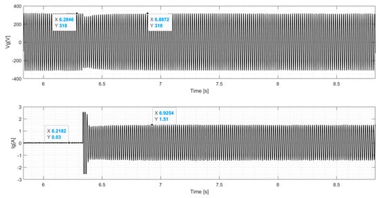
Figure 15.
Waveform of and with experimental SG dynamic loading.
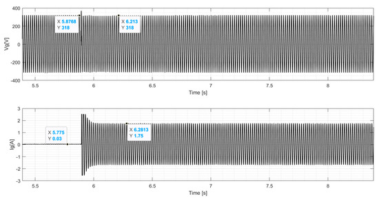
Figure 16.
Waveform for and with the experimental SG resistive load.
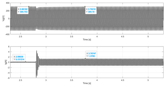
Figure 17.
Waveform for and with simulated SG dynamic loading.
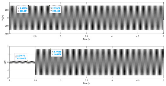
Figure 18.
Waveform for and with the resistive load SG simulation.
Regarding load insertion, there was a limitation due to the primary machine. The DCM possesses a power of 2 kW and the SG of 3 kVA in conjunction with the IG power, which meant that the primary machine worked at its current limit. However, for generation, it is recommended that the primary machine power is at least 60% above the generator power.
6. Conclusions
The excitation system proposed to replace the PMG excitation control used in DGS presented satisfactory results, thus demonstrating its viability. This was amply demonstrated in the performance of the results, both in terms of its environmental appeal for not using materials with rare earth elements and in the SEIG used due to its operating characteristics and low acquisition cost.
One of the problems solved through use of this system was in relation to the self-excitation speed of the IG at synchronous speed. Regarding the proposal to use the six-pole motor, it demonstrated good operational viability, although problems could arise due to the higher frequency of the voltage generated; this, however, was not the case, since the voltage generated by the IG was rectified and filtered to supply the SG field voltage.
Therefore, by comparing the simulated and experimental results, one notes that, even in the face of a dynamic load, the rotary excitation system with IG managed to restore the SG voltage to the nominal value as established in [32]. In this manner, the proposal presented in this article was validated, contributing, in a pioneering fashion, to rotary exciter systems with induction generators.
Author Contributions
Conceptualization, E.M., F.B.S., R.V.A.M., J.M.R. and G.C.G.; methodology, E.M., F.B.S. and G.C.G.; software and calculation, E.M. and F.B.S.; writing—preparation of the original draft, E.M. and F.B.S.; review and editing, E.M., F.B.S., R.V.A.M. and G.C.G.; supervision and final preparation, all authors. All authors have read and agreed to the published version of the manuscript.
Funding
This research received no external funding.
Data Availability Statement
The original contributions presented in the study are included in the article, further inquiries can be directed to the corresponding author.
Acknowledgments
The authors would like to express their gratitude to the Faculty of Electrical Engineering at the Federal University of Mato Grosso (UFMT) and the Mato Grosso Federal Institute of Technology (IFMT), particularly the Department of Electrical and Automation Engineering (DEEA), for providing the laboratory facilities essential for this research. Additionally, the authors extend their thanks to the Postgraduate Program in Electrical Engineering (PPGEELT) at the Faculty of Electrical Engineering (FEELT) of the Federal University of Uberlândia (UFU) for their support in executing this project.
Conflicts of Interest
The authors declare no conflicts of interest.
Nomenclature
| Number of poles | |
| Resistance and leakage reactance for stator windings | |
| Resistance and leakage reactance for rotor windings | |
| Electromagnetic torque | |
| Voltage, current and flux linkage stator for the zero axis | |
| Voltage, current and flux linkage rotor for the zero axis | |
| Voltage, current and flux linkage stator for the quadrature axis | |
| Voltage, current and flux linkage stator for the direct axis | |
| Voltage, current and flux linkage rotor for the direct axis | |
| Voltage, current and flux linkage rotor for the quadrature axis | |
| Is the angular velocity of the reference frame | |
| Is the base electrical angular velocity used to calculate the inductive reactance | |
| Is the electrical angular velocity and the mechanical angular speed | |
| Rotor mechanical speed | |
| Mechanical rotor position | |
| Voltage, current and flux linkage third damper winding axis | |
| Voltage, current and flux linkage second damper winding axis | |
| Voltage, current and flux linkage damper winding for the direct axis | |
| Voltage, current and flux linkage field winding for the direct axis | |
| Resistance of the third e second damper winding | |
| Resistance of the damper and field winding | |
| Magnetizing reactance direct axis and quadrature axis |
Appendix A
The electrical equations of the induction machine are given by
The mechanical equations are described by
The electrical equations of the synchronous machine in the rotor reference frame are given by
The electrical torque equation is described by
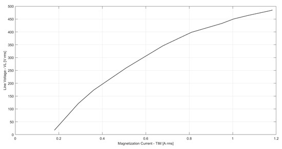
Figure A1.
IM magnetization curve of 0.37 kW IG.
Appendix B. Capacitor Specification for Self-Excitation
As with the work in [18], the confirmation of capacitor values is performed by experimental tests. However, no study currently exists that is able to determine these values in the form of a mathematical model.
To determine the values of the capacitors, the calculation of the minimum capacitance sizing was used as a basis, as presented in [9], where the induction generator was applied as if empty or at no load. If then, one considers that this reactive energy consumption is performed by magnetization reactance, here, the calculation to obtain the value of this minimum capacitance per phase is given by
where:
- f is the voltage frequency generated, given in [Hz];
- is the magnetizing reactance of the induction generator, given in [Ω].
For the value of the magnetization reactance obtained by testing the induction machine ( and the frequency of the six-pole motor in rotation of 1800 rpm as 90 Hz, one calculates
However, this calculation for capacitance is performed to configure the connection of the induction motor in parallel with the capacitances in , as shown in Figure A2. In this case, this configuration was applied to determine the values of and used as shown in Figure A3. Concerning the value of , the relationship encountered in [18] was implemented. Here, the value of is approximately 62% of the value of , which is equivalent to . The commercial values presented in Table A1 were used for testing. The voltage level with the calculated capacitance presented a very high voltage value on the generator terminals. Therefore, tests were carried out using other values, which are presented in Table A1. The results presented are for the voltage measured on the capacitor , where the single-phase voltage is generated in the AC at no load. As such, tests were performed with values up to the excitation limit of the machine.
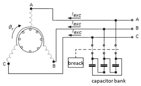
Figure A2.
Connecting the capacitors (adapted from [9]).
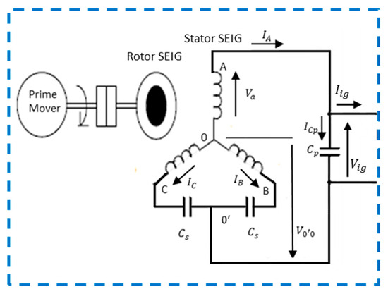
Figure A3.
Circuit representing the SEIG (adapted from [18]).
Table A1.
IG self-excitation test.
Table A1.
IG self-excitation test.
| Voltage IG | ||
|---|---|---|
| 518 [V rms] | ||
| 485 [V rms] | ||
| 431 [V rms] |
With values of below and below the IG presented difficulty with self-excitation.
Table A2.
IM parameters used in the IG.
Table A2.
IM parameters used in the IG.
| Parameters | Values |
|---|---|
| Nominal power | 0.37 [kW] |
| Nominal voltage | 220/380 [V rms] |
| Nominal (full load) current | 4.43/2.56 [A rms] |
| Poles | 6 |
| Nominal power factor | 0.70 |
| Nominal efficiency | 0.753 |
| Frequency | 60 [Hz] |
| Stator resistance, | 19.0 [Ω] |
| Rotor resistance, | 20.58 [Ω] |
| Magnetizing reactance, | 264.75 [Ω] |
| Stator reactance, | 10.45 [Ω] |
| Rotor reactance, | 24.39 [Ω] |
| Moment of inertia | 0.0025 [kgm2] |
Table A3.
Electrical values for the parameters of the capacitor bank.
Table A3.
Electrical values for the parameters of the capacitor bank.
| Parameters | Capacitor |
| Nominal voltage | 450 [V rms] |
| Frequency | 60 [Hz] |
| Settings | FUKAMI |
| Cs | 5 [] |
| Cp | 4 [] |
Table A4.
Nameplate data and the parameters for the electrics and mechanics of the synchronous motor.
Table A4.
Nameplate data and the parameters for the electrics and mechanics of the synchronous motor.
| Parameters | Values |
|---|---|
| Nominal power | 3 [k VA] |
| Nominal voltage | 110/220 [V rms] |
| Nominal (full load) current | 7.9 [A rms] |
| Nominal Field current | 1.45 [A rms] |
| Poles | 4 |
| Nominal power factor | 1 |
| Frequency | 60 [Hz] |
| Synchronous mechanical speed | 1800 [rpm] |
| Moment of inertia | 0.0466 [kgm2] |
| Constant of inertia | 0.414 [s] |
| Direct axis reactance, Xd | 2.125 pu |
| Saturated direct axis reactance, Xds | 1.724 pu |
| Quadrature axis reactance, Xq | 1.4875 pu |
| Direct axis transient reactance, X′d | 0.425 pu |
| Direct axis subtransient reactance, X″d | 0.255 pu |
| Quadrature axis subtransient reactance, X″q | 0.2295 pu |
| Direct axis short circuit transient time constant, T′d | 2.4 [s] |
| Direct axis short circuit subtransient time constant, T″d | 0.02 [s] |
| Quadrature axis short circuit subtransient time constant, T″q | 0.02 [s] |
| Leakage reactance, Xl | 0.215 pu |
| Stator dc resistance, Rs | 0.0681 pu |
Table A5.
Nameplate data and the parameters for the electrics and mechanics of the IM.
Table A5.
Nameplate data and the parameters for the electrics and mechanics of the IM.
| Parameters | Values |
|---|---|
| Nominal power | 0.18 [kW] |
| Nominal voltage | 220/380 [V rms] |
| Nominal (full load) current | 1.14/0.66 [A rms] |
| Poles | 4 |
| Nominal power factor | 0.65 |
| Nominal efficiency | 0.64 |
| Frequency | 60 [Hz] |
| Moment of inertia | 0.0006 [kgm2] |
References
- Vanço, W.E.; Silva, F.B.; Monteiro, J.R.; de Oliveira, J.M.; Alves, A.C.; Júnior, C.A. Analysis of the oscillations caused by harmonic pollution in isolated synchronous generators. Electr. Power Syst. Res. 2017, 147, 280–287. [Google Scholar] [CrossRef]
- Vanco, W.E.; Silva, F.B.; Goncalves, F.A.S.; Silva, E.O.; Bissochi, C.A.; Neto, L.M. Experimental analysis of a self-excited induction generators operating in parallel with synchronous generators applied to isolated load generation. IEEE Lat. Am. Trans. 2016, 14, 1730–1736. [Google Scholar] [CrossRef]
- Vanço, W.E.; Silva, F.B.; de Oliveira, J.M.M.; Almeida Monteiro, J.R.B. Effects of harmonic pollution on salient pole synchronous generators and on induction generators operating in parallel in isolated systems. Int. Trans. Electr. Energy Syst. 2020, 30, e12359. [Google Scholar] [CrossRef]
- Silva, F.B.; Vanço, W.E.; da Silva Gonçalves, F.A.; Bissochi, C.A., Jr.; de Carvalho, D.P.; Guimarães, G.C. A proposal for the study of voltage sag in isolated synchronous generators caused by induction motor start-up. Electr. Power Syst. Res. 2016, 140, 776–785. [Google Scholar] [CrossRef]
- Laliberte, G. A Comparison of Generator. Excitation Systems. Our Energy Working for YouTM. Power Topic #6008|Technical Information from Cummins Power. Bulletin 6451356 Produced in U.S.A. 2/23 ©2023 Cummins Inc. Available online: https://petroleoeindustria.trienergy.com/wp-content/uploads/2021/03/Sistemas-de-Excitacion-en-Generadores.pdf (accessed on 20 May 2024).
- Snyder, B. Excitation Selections. Electric Power, Caterpillar Inc. LEXE1643-00 Feb 2020© 2020 Caterpillar. All Rights Reserved. Excitation Selections|Cat|Caterpillar. Available online: https://carolinacat.com/content/uploads/sites/4/2020/07/Excitation-Selections.pdf (accessed on 20 May 2024).
- Yousefi-Talouki, A.; Pescetto, P.; Pellegrino, G.; Boldea, I. Combined Active Flux and High-Frequency Injection Methods for Sensorless Direct-Flux Vector Control of Synchronous Reluctance Machines. IEEE Trans. Power Electron. 2017, 33, 2447–2457. [Google Scholar] [CrossRef]
- Boldea, I.; Tutelea, L.N.; Parsa, L.; Dorrell, D. Automotive Electric Propulsion Systems with Reduced or No Permanent Magnets: An Overview. IEEE Trans. Ind. Electron. 2014, 61, 5696–5711. [Google Scholar] [CrossRef]
- Silva, F.B.; da Silva Gonçalves, F.A.; Vanço, W.E.; de Carvalho, D.P.; Bissochi, C.A., Jr.; Monteiro, R.V.A.; Guimarães, G.C. Application of bidirectional switches in the development of a voltage regulator for self-excited induction generators. Int. J. Electr. Power Energy Syst. 2018, 98, 419–429. [Google Scholar] [CrossRef]
- Vanco, W.E.; Silva, F.B.; De Oliveira, C.M.R.; Monteiro, J.R.B.A.; De Oliveira, J.M.M. A Proposal of Expansion and Implementation in Isolated Generation Systems Using Self-Excited Induction Generator With Synchronous Generator. IEEE Access 2019, 7, 117188–117195. [Google Scholar] [CrossRef]
- Poddar, G.; Joseph, A.; Unnikrishnan, A.K. Sensorless variable speed controller for existing fixed-speed wind power generator with unity-power-factor operation. IEEE Trans. Ind. Electron. 2003, 50, 1007–1015. [Google Scholar] [CrossRef]
- Marra, E.G.; Pomilio, J.A. Induction-generator-based system providing regulated voltage with constant frequency. IEEE Trans. Ind. Electron. 2000, 47, 908–914. [Google Scholar] [CrossRef]
- Boldea, I. Variable Speed Generators (The Electric Generators Handbook); CRC Press: Boca Raton, FL, USA, 2005. [Google Scholar]
- Chan, T.F.; Lai, L.L. A novel single-phase self-regulated self-excited induction generator using three phase machine. In Proceedings of the IEEE International Conference on Electric Machines and Drives (IEMDC), Seattle, WA, USA, 9–12 May 2001; pp. 204–208. [Google Scholar]
- Ion, C.P.; Marinescu, C. Three-phase induction generators for single-phase power generation: An overview. Renew. Sustain. Energy Rev. 2013, 22, 73–80. [Google Scholar] [CrossRef]
- Chan, T.F.; Lai, L.L. Single-phase operation of a three-phase induction generator with Smith connection. In Proceedings of the 2002 IEEE Power Engineering Society Winter Meeting. Conference Proceedings, New York, NY, USA, 27–31 January 2002; pp. 47–54. [Google Scholar]
- Bansal, R.C. Three-Phase Self-Excited Induction Generators: An Overview. IEEE Trans. Energy Convers. 2005, 20, 292–299. [Google Scholar] [CrossRef]
- Fukami, T.; Imamura, M.; Miyamoto, T. A new self-regulated selfexcited single-phase induction generator using a squirrel-cage three-phase induction machine. In Proceedings of the 1995 International Conference on Energy Management and Power Delivery EMPD 95, Singapore, 21–23 November 1995; pp. 867–872. [Google Scholar]
- Fukami, T.; Kaburaki, Y.; Kawahara, S.; Miyamoto, T. Performance analysis of a self-regulated self-excited single-phase induction generator using a three-phase machine. IEEE Trans. Energy Convers. 1999, 14, 622–627. [Google Scholar] [CrossRef]
- Chan, T.F. Performance analysis of a three-phase induction generator connected to a single-phase power system. IEEE Trans. Energy Convers. 1998, 13, 205–213. [Google Scholar] [CrossRef]
- Chatterjee, A.; Chatterjee, D. Analysis and control of photovoltaic-assisted three-phase induction machine operating as single-phase micro-wind generator. IET Gener. Transm. Distrib. 2016, 10, 2165–2176. [Google Scholar] [CrossRef]
- Gao, S.; Bhuvaneswari, G.; Murthy, S.S.; Kalla, U. Efficient voltage regulation scheme for three-phase self-excited induction generator feeding single-phase load in remote locations. IET Renew. Power Gener. 2014, 8, 100–108. [Google Scholar] [CrossRef]
- Kim, B.; Pietrzak-David, M.; Maussion, P.; Bun, L. Novel structure of single-phase generator from three-phase induction machine: Modeling and simulation. In Proceedings of the IECON 2017—43rd Annual Conference of the IEEE Industrial Electronics Society, Beijing, China, 29 October–1 November 2017; pp. 7653–7659. [Google Scholar]
- Wang, Y.-J.; Lee, M.-H. A Method for Balancing a Single-Phase Loaded Three-Phase Induction Generator. Energies 2012, 5, 3534–3549. [Google Scholar] [CrossRef]
- Nakorn, P.; Machot, P.; Kinnares, V.; Manop, C. Study of Three-phase Self-excited Induction Generator Operating as Single-phase Induction Generator Supplying Non-linear Load. In Proceedings of the 2021 18th International Conference on Electrical Engineering/Electronics, Computer, Telecommunications and Information Technology (ECTI-CON), Chiang Mai, Thailand, 19–22 May 2021; pp. 806–809. [Google Scholar]
- Yukhalang, S.; Sopapirm, T.; Kinnares, V. Three-phase Self-Excited Induction Generator Operating as Single-phase Induction Generator using Static VAR Compensator. In Proceedings of the 2023 20th International Conference on Electrical Engineering/Electronics, Computer, Telecommunications and Information Technology (ECTI-CON), Nakhon Phanom, Thailand, 9–12 May 2023; pp. 1–7. [Google Scholar]
- Yukhalang, S.; Sawetsakulanond, B.; Kinnares, V. Performance evaluation of three-phase induction generator operating as grid connected single-phase induction generator using electronic capacitor. In Proceedings of the 2015 18th International Conference on Electrical Machines and Systems (ICEMS), Pattaya, Thailand, 25–28 October 2015; pp. 743–747. [Google Scholar]
- Simões, M.G.; Farret, F.A. Modeling and Analysis with Induction Generator, 3rd ed.; CRC Press: Boca Raton, FL, USA, 2014; pp. 87–100. [Google Scholar]
- Krause, P.C.; Wasynczuk, O.; Sudhoff, S.D.; Pekarek, S.D. Analysis of Electric Machinery and Drive Systems, 3rd ed.; EUA: Institute of Electrical and Electronics Engineers; IEEE Press: Hoboken, NJ, USA, 2013; pp. 201, 262. [Google Scholar]
- Chauhan, Y.K.; Jain, S.K.; Singh, B. Performance of a three-phase Self-Excited Induction Generator with Static Synchronous Series Compensator. In Proceedings of the 2010 Joint International Conference on Power Electronics, Drives and Energy Systems & 2010 Power India, New Delhi, India, 20–23 December 2010; pp. 1–6. [Google Scholar]
- Hamilton, E.R.; Hamer, P.S.; Undrill, J.; Manson, S. Considerations for generation in an islanded operation. IEEE Trans. Ind. Appl. 2010, 46, 2289–2298. [Google Scholar] [CrossRef]
- NEMA MG-1; Motors and Generators. National Electrical Manufacturers Association: Rosslyn, VA, USA, 2016.
Disclaimer/Publisher’s Note: The statements, opinions and data contained in all publications are solely those of the individual author(s) and contributor(s) and not of MDPI and/or the editor(s). MDPI and/or the editor(s) disclaim responsibility for any injury to people or property resulting from any ideas, methods, instructions or products referred to in the content. |
© 2024 by the authors. Licensee MDPI, Basel, Switzerland. This article is an open access article distributed under the terms and conditions of the Creative Commons Attribution (CC BY) license (https://creativecommons.org/licenses/by/4.0/).