Article

Impact of Aromatic Hydrocarbons on Emissions in a Custom-Built High-Pressure Combustor

by
Qiming Yu
1,*,† and
Bhupendra Khandelwal
2,‡
1
Department of Mechanical Engineering, The University of Sheffield, Sheffield S10 2TN, UK
2
Department of Aerospace Engineering and Mechanics, University of Alabama, Tuscaloosa, AL 35487, USA
*
Author to whom correspondence should be addressed.
Current address: Western Bank, Sheffield S10 2TN, UK.
Bhupendra Khandelwal served as the project supervisor for this research.
Energies 2024, 17(16), 3939; https://doi.org/10.3390/en17163939
Submission received: 16 June 2024 / Revised: 25 July 2024 / Accepted: 6 August 2024 / Published: 8 August 2024
(This article belongs to the Special Issue Advanced Combustion Technologies and Emission Control)

Abstract

:
This study addresses the ongoing demand for increased efficiency and reduced emissions in turbomachinery combustion systems. A custom-built high-pressure combustor was designed and manufactured at the Low Carbon Combustion Centre (LCCC) of the University of Sheffield to investigate the impact of different aromatic hydrocarbons on emission rates. The research involved the comprehensive testing of Jet−A1 fuel and six aromatic species blends under high-pressure conditions of 10 bar. Based on the numerical CFD simulations by ANSYS 19.2, tangential dual air injection and a strategically placed V-shaped baffle plate were utilised to enhance fuel-air mixing and combustion stability. Experimental results demonstrated a negative correlation between combustion temperature and particulate matter (PM) emissions, with higher temperatures yielding lower PM emissions. Unburned hydrocarbons (UHCs), nitrogen oxides ( N O x ), carbon monoxide ( C O ), and carbon dioxide ( C O 2 ) emissions were also analysed. Ethylbenzene produced the highest UHC and C O emissions, while Indane exhibited the lowest levels of these pollutants, suggesting more complete combustion. O−xylene generated the highest N O x emissions, correlating with its higher combustion temperatures. This research enhances our understanding of gas turbine combustor design and the combustion behaviour of aromatic species, providing valuable insights for developing low-emission, high-efficiency gas turbine combustion technologies.

1. Introduction

Turbomachines have been pivotal in various applications, from civilian uses to military operations, with their importance continually increasing. For instance, advancements in aircraft gas turbines have enabled global travel and supported over 56 million jobs in the air transport industry as of 2015 [1]. Given the increasing global population and economic growth demands, the development of gas turbine technology remains essential. A critical aspect of this technology is the combustion system, which significantly impacts the overall efficiency and performance of gas turbines. Despite the relatively straightforward operation of combustion chambers, their design is highly complex. It involves mixing air with atomised fuel, managing combustion, and converting chemical energy into mechanical power. Combustion within gas turbines features complex flow patterns, such as backflows, circulations, and turbulence, necessitating the careful consideration of aerodynamics, thermodynamics, and complex chemical reactions [2]. Although gas turbine combustor development has been pursued nearly 80 years [3], theoretical support for high-pressure combustor design remains insufficient, often relying on empirical experience and numerical simulations [4,5,6].
According to the 2015 aviation emission report, gas turbine combustion processes emit pollutants such as C O 2 , particulate matter (PM), and N O x [1]. These emissions pose serious environmental and health risks, including contributing to the greenhouse effect, acid rain, and respiratory problems [7]. Consequently, governments, such as the UK, have enacted stringent environmental regulations aimed at reducing greenhouse gas emissions by at least 80% from 1990 levels by 2050 [8]. Therefore, developing low-emission gas turbine combustors is of paramount importance.

1.1. Emissions

Emissions from gas turbine combustion processes generally consist of several key pollutants, including carbon monoxide ( C O ), nitrogen oxides ( N O x ), unburnt hydrocarbons (UHCs), and particulate matter (PM). Each of these emissions presents unique challenges and environmental impacts, which are critical to understanding and mitigating in the context of developing efficient and environmentally friendly combustion systems [2].
C O is primarily formed due to incomplete combustion when there is insufficient oxygen to convert carbon in the fuel to carbon dioxide ( C O 2 ). This situation often arises in fuel-rich zones within the combustion chamber. Factors contributing to incomplete combustion include inadequate burning rates in the primary zone, poor mixing of fuel and air, and quenching of the combustion process by cooler air entering the combustion chamber. High levels of C O are hazardous as they can bind with haemoglobin in the blood, reducing the oxygen-carrying capacity and leading to potential health risks such as respiratory issues and cardiovascular diseases [2,9].
N O x are generated during high-temperature combustion processes through the oxidation of nitrogen present in the air. The combustion temperature significantly influences N O x formation, with higher temperatures promoting more N O x formation (Figure 1) [2].
N O x emissions are particularly concerning due to their role in forming ground-level ozone and fine particulate matter, which are key components of smog. These emissions can lead to respiratory problems and environmental degradation and contribute to the formation of acid rain [2].
N 2 + O N O + N
N O + H 2 O N O 2 + O H
The Zeldovich mechanism explains the formation of N O x , indicating the direct oxidation of nitrogen ( N 2 ) in the combustion air to form nitric oxide ( N O ), which can further oxidise to nitrogen dioxide ( N O 2 ) [2].
UHCs refer to fuel components that do not combust completely and are released into the atmosphere. UHC emissions result from poor fuel atomisation, inadequate mixing of fuel and air, and incomplete combustion processes. These hydrocarbons can contribute to ground-level ozone and smog formation, posing health risks such as respiratory and cardiovascular diseases [2,10].
PM emissions, particularly soot, are formed during the combustion of hydrocarbon fuels. PM consists of tiny particles that can penetrate the lungs and bloodstream deep, causing various health problems, including respiratory and cardiovascular diseases, and can contribute to environmental issues such as reduced visibility and acid rain. PM emissions are influenced by factors such as fuel composition, combustion temperature, and the presence of aromatic hydrocarbons [2].
Recent studies have highlighted the different emission profiles during combustion processes. For instance, Zheng et al. investigated the impact of various aromatic structures on particulate matter (PM) emissions in jet engines, testing 16 different species blended with jet fuels. They found that di-aromatics and cyclo-aromatics produced significantly higher PM emissions than alkyl-benzenes, with 3-isopropylamine showing the lowest PM formation. This suggests that careful selection of aromatic species can help reduce emissions in future fuels. The study utilised a novel flame luminosity imaging technique, which correlated well with traditional PM measurement methods [11]. Almohammadi et al. researched the impact of different aromatic species and their concentrations on emissions and performance in a compression-ignition engine. They found that higher aromatic content in fuel blends led to increased particulate matter (PM), carbon monoxide (CO), and uniform hydrocarbon (UHC) emissions. Polycyclic aromatics had a greater tendency to produce pollutants compared to monocyclic aromatics. These findings highlight the importance of selecting appropriate aromatic species to minimise emissions in fuel formulations [12]. Chapman et al. optimised aromatic species in fuels to reduce emissions, finding that an 8% tert-butylbenzene blend significantly reduced particulate matter (PM) and nitrogen oxide ( N O x ) emissions due to better atomisation and combustion efficiency [13]. Singh et al. found that single-ring aromatics like toluene and xylene resulted in lower PM and N O x emissions compared to multi-ring aromatics, emphasising the importance of molecular structure in emissions profiles [14]. Dandajeh et al. investigated the emissions of polycyclic aromatic hydrocarbons (PAHs) and soot in diesel engines. They found that the combustion characteristics, such as heat release rates and high-pressure conditions, significantly influence these emissions [15]. Similarly, Talibi et al. explored the impact of methyl branching in aromatic hydrocarbons on diesel engine combustion and emissions. Their findings indicate that the structure of aromatic hydrocarbons can significantly alter the emission profiles, particularly under high-pressure conditions [16]. Moreover, several reviews and experimental studies have provided insights into soot and PAH formation mechanisms under high-pressure combustion environments. Chu et al. conducted a comprehensive review of soot formation in high-pressure combustion, emphasising the challenges and current understanding of how aromatic hydrocarbons contribute to soot production [17]. Additionally, Liu et al. investigated the effects of preheating temperature on PAH and soot formation in high-pressure methane/air co-flow flames, revealing that increased pressure and temperature conditions significantly enhance PAH and soot emissions [18]. Extending this research, Kalvakala and Aggarwal examined PAH and soot emissions in oxygenated ethylene diffusion flames at elevated pressures, finding that oxygenated compounds in fuel can reduce soot formation [19]. Similarly, Liang et al. studied PAH and soot formation in laminar partially premixed co-flow flames fueled by primary reference fuels at elevated pressures, highlighting the influence of pressure on soot morphology and size distribution [20].

1.2. Synthetic Fuels

The development of alternative fuels has significantly advanced due to the cost and emission problems associated with conventional jet fuel. Alternative fuels can be broadly categorised based on their feedstock. Most synthetic fuels are produced from fossil feedstocks such as natural gas and coal using the Fischer-Tropsch (FT) process, which is the most mature alternative fuel production pathway. Recently, the FT process has also targeted bio-based feedstocks, which have significant potential for future applications. Other alternative fuels utilise bio-feedstocks such as animal fat, oilseeds, and waste oil. Over time, more feedstocks are being discovered that have the potential to be converted into jet fuel. Benefiting from these alternative feedstocks and production pathways, the industry is now capable of producing aviation fuels that contain small amounts of aromatics, such as synthetic paraffinic kerosene (SPK), Fischer-Tropsch derived fuels, and gas-to-liquid (GTL) fuels [21,22,23]. As part of the synthetic fuels, aromatic hydrocarbons are also crucial for swelling seals in fuel systems and provide higher energy density per unit mass [24,25]. The swelling effect of these aromatic compounds on seals is essential for maintaining the integrity and functionality of fuel systems, especially with the transition to synthetic and sustainable aviation fuels. Hamilton and Khandelwal have developed a novel seal compatibility test rig that measures the swelling and shrinkage of different elastomer seals in real-time, providing valuable insights into how these aromatic species interact with seal materials [26]. Research indicates that aromatic hydrocarbons can induce seal swelling, which is critical for preventing fuel leakage and ensuring the durability of seals. The study by Khandelwal and colleagues showed that nitrile elastomers exhibit significant swelling when exposed to Jet−A1 fuel, while aromatic-free SPK fuels cause notable shrinkage [27]. These findings underscore the importance of selecting appropriate aromatic content and species in synthetic fuels to maintain seal compatibility and performance in aviation fuel systems. Consequently, these alternative fuels may cause leaks and are unsuitable to be directly applied in current commercial flights [28]. ASTM D7566 stipulates that the blending ratio for FT SPK should be up to 50/50 by volume and 30/70 for alcohol-to-jet (ATJ) fuels. A minimum aromatic content of 8% is required for synthetically produced fuels, necessitating blending with conventional fuels or the addition of synthetic aromatics. Not all aromatic types produce the same levels of smoke and emissions. Therefore, properly selecting synthetic aromatics is crucial for optimising emissions and operability. These benefits may be vital for the future development of fuels and engines [29].

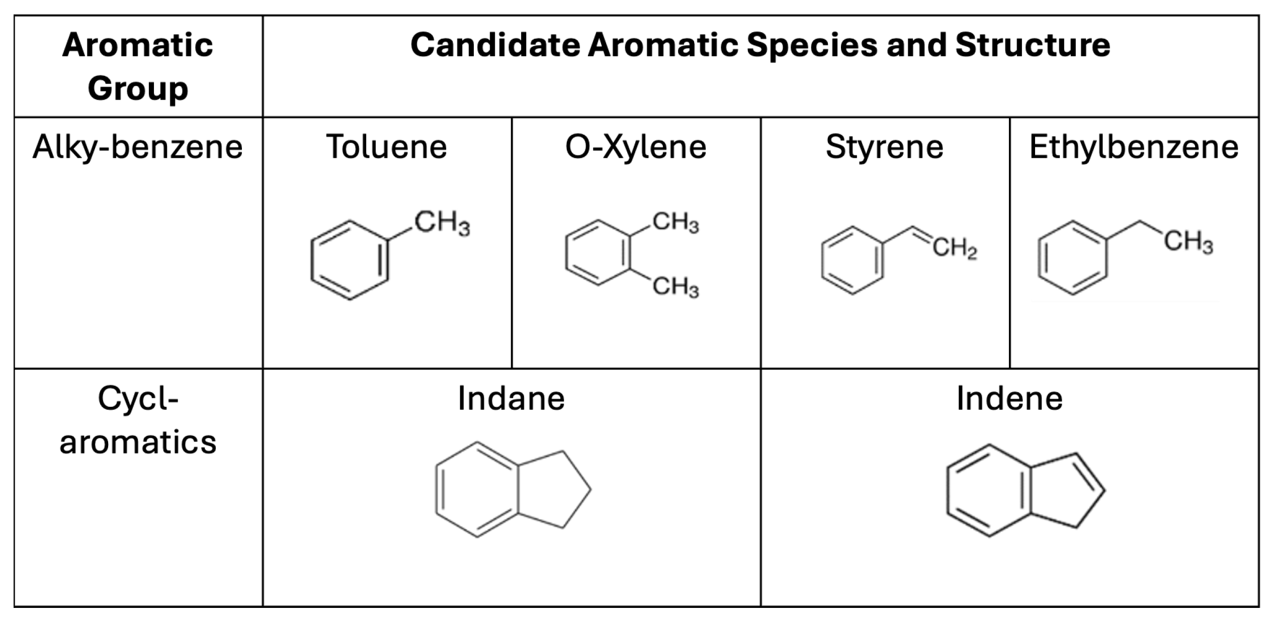
1.3. Selection of Aromatic Species

As reviewed in Section 1.1, the combustion behaviours of various aromatic hydrocarbons such as toluene, o−xylene, styrene, ethylbenzene, indene, and indane (chemical structures shown in Figure 2) have been extensively studied due to their significant impact on combustion processes and emissions. Toluene, a common aromatic fuel component, is known for its high heat of combustion and its role in soot formation. Research indicates that the structure of toluene, which includes a single benzene ring with a methyl group, contributes to its high reactivity in combustion environments, leading to the formation of soot precursors such as polycyclic aromatic hydrocarbons (PAHs) [11,30]. Similarly, o−xylene, another methyl-substituted benzene, exhibits comparable combustion characteristics, although the position of the methyl groups affects its reaction pathways and soot-formation tendencies. Styrene and ethylbenzene derived from benzene also play crucial roles in combustion chemistry. Styrene, with its vinyl group, participates in complex reaction mechanisms that can lead to the formation of soot and other combustion byproducts. Ethylbenzene, being ethyl-substituted benzene, shows different combustion behaviour compared to toluene and xylene, often resulting in varied emission profiles [31,32]. Indene and indane, although less commonly studied, have unique structural properties influencing their combustion. Indene, with its fused ring structure, and indane, a saturated indene derivative, contribute differently to soot formation and combustion efficiency. Studies have shown that indene produces higher amounts of soot due to its unsaturated ring structure, while indane, a saturated compound, has lower sooting tendencies [33,34].

1.4. Research Aim and Objectives

By addressing the gaps in understanding the effects of aromatic hydrocarbons under high-pressure combustion, this research aims to provide test data on the aerodynamics and emissions of various aromatic hydrocarbons in a custom-built high-pressure combustion system. This paper details the development process of a custom-built high-pressure combustor. Inspired by the work of Lefebvre and Longwell [2,5,35], a novel V-shaped baffle plate was built and implemented to enhance the aerodynamic performance of the combustor. This research investigates the combustion of Jet−A1 fuel and six different aromatic species under high-pressure conditions (10 bar). The objective is to compare the emissions of particulate matter (PM), unburnt hydrocarbons (UHCs), nitrogen oxides ( N O x ), carbon monoxide (CO), and carbon dioxide ( C O 2 ) from these fuels, providing new insights into the impact of aromatic species on pollutant emissions.

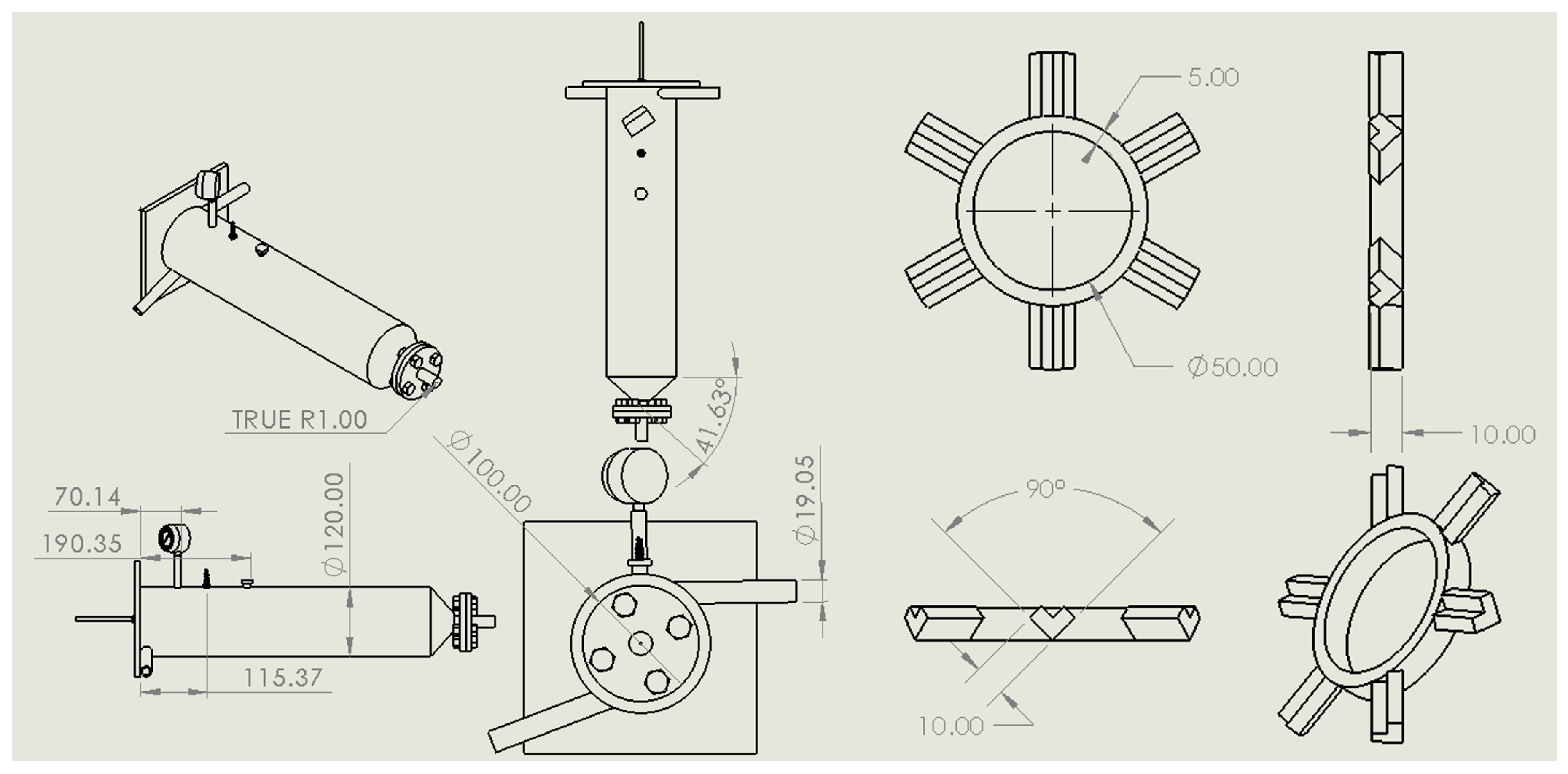
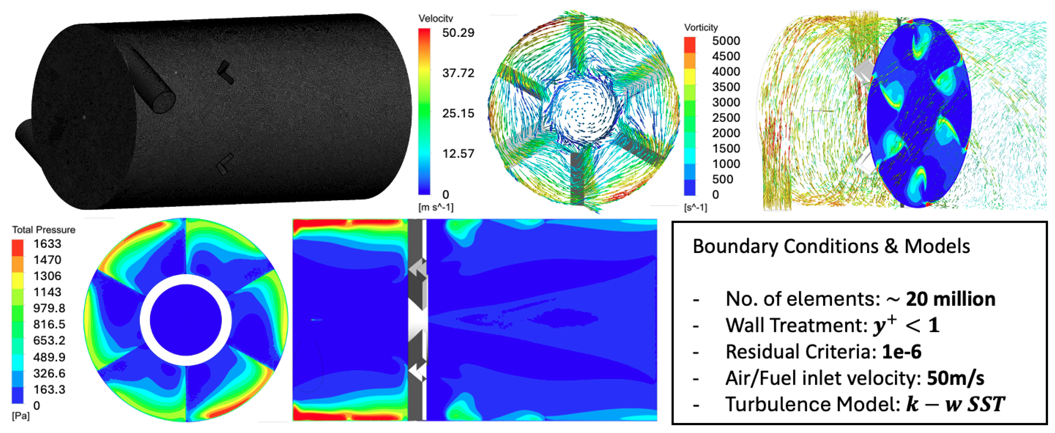
2. Design Methodology

New design specifications were drawn up and evaluated based on existing knowledge of combustor design and extensive literature reviews. The objective was to design, manufacture, and test a combustion chamber capable of withstanding high-pressure and high-temperature environments. The combustor was tested with Jet−A1 fuel blended with different aromatic species. The size of the new combustor was increased to reduce pressure loss by allowing more space for the atomised fuel and airflow to mix effectively. The combustor was designed with a circular shape to maintain a consistent flow pattern and uniform combustion.
Research in the field of high-pressure gas turbine combustors has highlighted the importance of designing for both aerodynamics and thermodynamics. For instance, a study by Lefebvre and Ballal emphasised the need for the adequate mixing of fuel and air to achieve complete combustion and reduce emissions [3]. Additionally, studies on high-temperature combustors, such as the work conducted at the National Aerospace Laboratory in Tokyo, have demonstrated that optimising the size and shape of the combustor can significantly improve performance under high-pressure conditions [36]. The design incorporated a double tangential air injection system to create a swirl flow inside the combustion chamber, which is crucial for increasing flame stability and enhancing combustion efficiency. The swirl flow helps create a recirculation zone, stabilising the flame and ensuring complete combustion. To provide a high-pressure environment for the fuel tests, the internal pressure of each new combustion chamber was designed to exceed 10 bar. This requirement is aligned with the need to simulate real operational conditions of gas turbines, where high pressure is essential for achieving high efficiency and low emissions.

2.1. Fuel Atomiser and Ignitor Design

As shown in Figure 3, the fuel injector utilised is a modified M16 bolt, which was meticulously drilled and threaded to accommodate a commercially available orifice securely mounted onto a steel plate. This setup is crucial for precisely controlling fuel injection into the combustion chamber, ensuring a consistent and directed spray pattern. The the orifice size, specifically chosen for its 0.1 mm diameter, plays a vital role in atomising the fuel efficiently, particularly under the minimal operational pressure of 7 bar, as this allows for optimal atomisation and mixture with air, enhancing combustion effectiveness.
For ignition, the system incorporates a standard automotive ignition setup consisting of a robust Gammatronix electronic ignition system powered by a 12 V car battery. This is paired with an NGK TR5A-10 spark plug, selected for its deep reach into the combustion chamber and its compatibility with the extreme temperatures expected during tests. The spark plug features a taper seat type without a gasket and a resistor, which is crucial for reducing electromagnetic interference within the system. The chosen spark plug has a heat rating of 5, indicative of its ‘hot’ characteristic, which is essential for maintaining high temperatures within the combustion chamber, ensuring thorough fuel combustion.

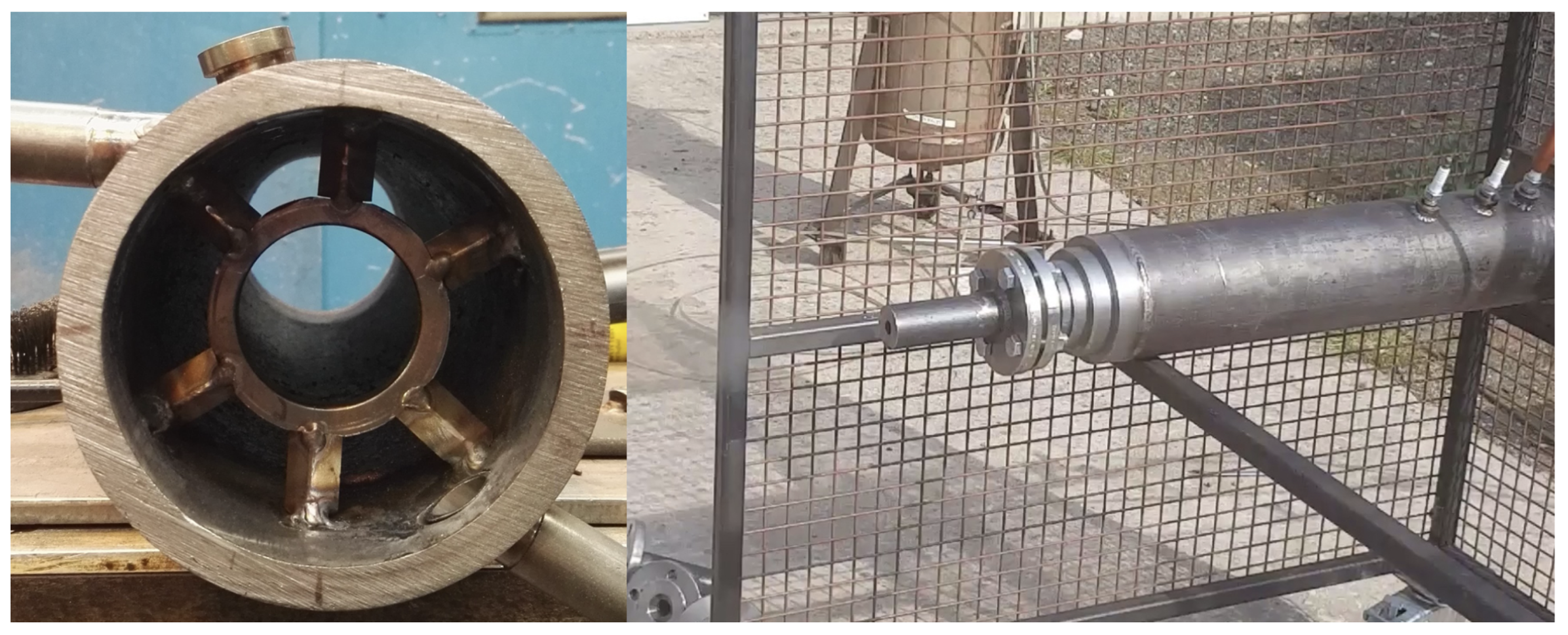
2.2. Baffle Plate Design

To stabilise the flame and prevent it from escaping the combustion chamber, a novel baffle plate was designed to serve as the flame stabiliser, as shown in Figure 4. Inspired by the studies conducted by Baxter and Lefebvre (1991) [37], the designed baffle plate consists of an O-ring and six V-shaped legs. The specifications of the baffle plate are detailed in Figure 4 and Figure 5. The design of the baffle plate was guided by principles of flame stabilisation and combustion efficiency. The research by Baxter and Lefebvre highlighted the effectiveness of such structures in creating recirculation zones that anchor the flame and enhance combustion stability [37]. Their work demonstrated that including strategically designed flame holders can significantly improve the stability and efficiency of combustion systems.
ANSYS CFD simulations were employed to optimise the placement and design of the baffle plate as displayed in Figure 6.
Although the CFD process is not displayed in this paper, it played a crucial role in determining the optimal location for the baffle plate and enhancing the overall design. The CFD analysis led to the decision to place the baffle plate 57 mm away from the fuel atomiser, which has a spray angle of 70 degrees. This placement was chosen based on the simulation results, which indicated that this distance would create an optimal recirculation zone, ensuring stable and efficient combustion. Previous studies have also emphasised the importance of precisely placing flame stabilisers to achieve desired combustion characteristics. A follow-up paper that shows the detailed CFD design and mixing performance with the baffle plate with the comparison of different multi-phase models will be presented in the future. Overall, the design and placement of the baffle plate were crucial in achieving stable combustion and preventing flame blowout.

2.3. Fuel Preparation

To find the impact of different types and amounts of aromatics on combustor emissions under high pressure (10 bar), six groups of fuels with varying aromatic species were prepared for testing as reviewed in Section 1.1, Section 1.2 and Section 1.3. As listed in Table 1, the selected aromatics—toluene, O−xylene, styrene, ethylbenzene, indene, and indane, were chosen for their distinct molecular structures and varying auto-ignition temperatures, influencing their behaviour in combustion processes. These properties influence how each compound behaves under high-pressure combustion conditions. Studies such as those by the Environmental Protection Agency (EPA) have demonstrated that specific aromatic hydrocarbons, like toluene and xylene, significantly contribute to soot formation due to their high soot yield potential [11,38]. Each aromatic compound was blended with a base solvent in fixed mass proportions of 13%. The base solvent, known as the banner solvent, consists primarily of straight-chain paraffin hydrocarbons ranging from C 10 to C 13 . The preparation of these fuel blends and the subsequent testing were designed to provide insights into how different aromatic structures influence emissions in high-pressure combustion environments.

2.4. Data Acquisition Systems

The measurement of temperature and pressure is critical in understanding and optimising the performance of gas turbine combustors. Accurate data acquisition systems (DAQ) are essential for capturing the high-frequency and high-temperature conditions typical of these environments. Based on the variables that needed to be measured, the instruments used were categorised into three groups: temperature sensors, pressure sensors, and flow rate measurement instruments.

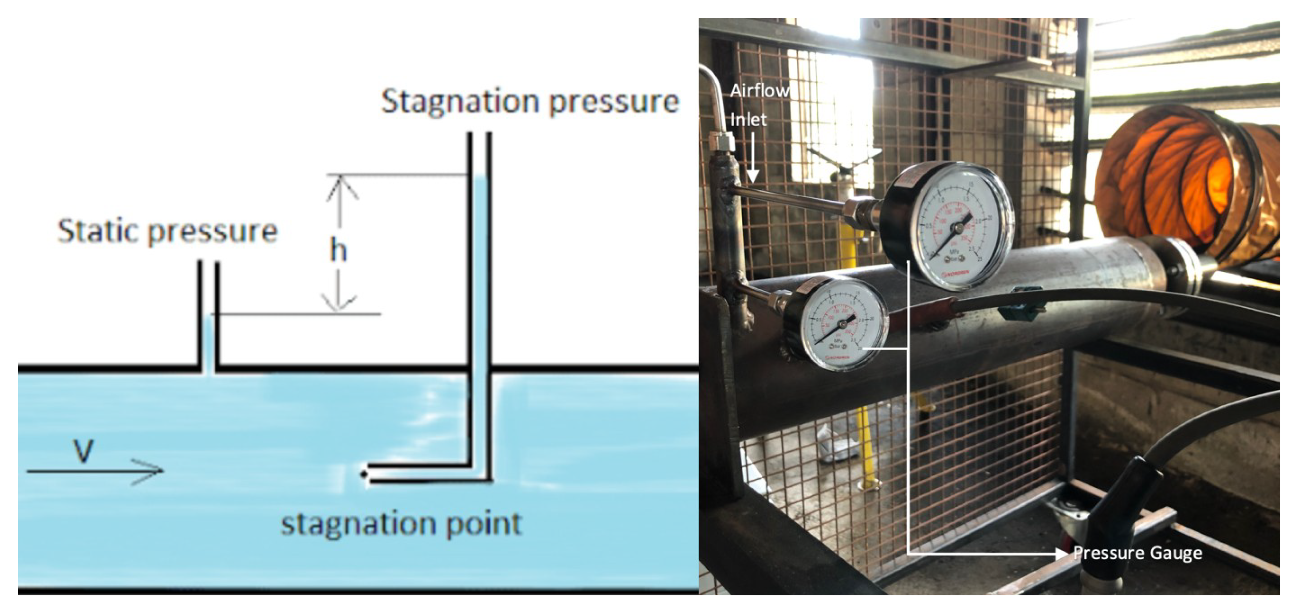
2.4.1. Temperature and Pressure

Due to the high thermal conductivity and radiation within the combustion chamber, both the inner and surface temperatures were measured using thermocouples and double-laser infrared Thermometers. Thermocouples are widely used in high-temperature applications due to their accuracy and durability, making them suitable for measuring the rapid temperature changes in gas turbine combustors. Infrared thermometers provide non-contact temperature readings, which are essential for obtaining surface temperature measurements without interfering with the combustor operation.
Pressure measurements were conducted using pressure gauges connected to the combustion chamber, as shown in Figure 7. These gauges were mounted through unused ignition holes to ensure that they did not disrupt the combustion process. Accurate pressure measurement is vital for monitoring the combustion process and ensuring safe and efficient operation.
Elevated air inlet pressure was used to determine the stable air-fuel ratio (AFR) range of the designed combustors while maintaining fixed fuel inlet pressure until the combustor blew out. Recording the live air-fuel ratio was necessary to identify the highest AFR at which the combustor could operate stably. As shown in Figure 8, live static pressure values were measured using two pressure gauges connected to an air inlet pipe. The principles and calculations used are shown in the following equations. Firstly, by measuring the static pressure at both ends of the air inlet pipe, the head loss ( h f ) can be calculated using the steady flow energy equation. According to the Bernoulli Equation, the airflow velocity (v) can be calculated as:
P t o t a l = P s t a t i c + 1 2 ρ v 2
Then, the mass flow rate of the air inlet was calculated, and the air-fuel ratio (AFR) can be determined using the following equation.
A F R = m ˙ a i r m ˙ f u e l
These measurements are critical for optimising combustor performance. The use of advanced data acquisition systems, as described by Gianinoni et al. (2020) ensures the accurate capture of high-frequency data necessary for analyzing combustion dynamics and improving combustor design [39].

2.4.2. Smoke and P M Emissions

To evaluate the impact of different aromatic contents on the pollutant emissions of the designed combustors, smoke and particulate matter (PM) were selected as key variables to be measured. Measuring these emissions provides critical insights into the environmental impact and efficiency of combustion processes. Various advanced techniques and instruments have been employed to accurately measure smoke and PM emissions in gas turbine engines.

Measurement Techniques

For PM emissions, the measuring instrument used was the laser-induced incandescence (LII-300, Artium Technologies Inc., Sunnyvale, CA, USA). LII is a sophisticated technique that measures soot particles by detecting their emitted light. The principle behind LII involves exposing soot particles to a short, energetic laser pulse, heating them to approximately 3500 °C. The high temperature causes the soot particles to emit light, the intensity of which correlates with the volume of PM emissions. Studies have shown that LII provides a highly sensitive and accurate measurement of soot particles, making it ideal for high-pressure combustion environments [39].

Instrumentation and Data Collection
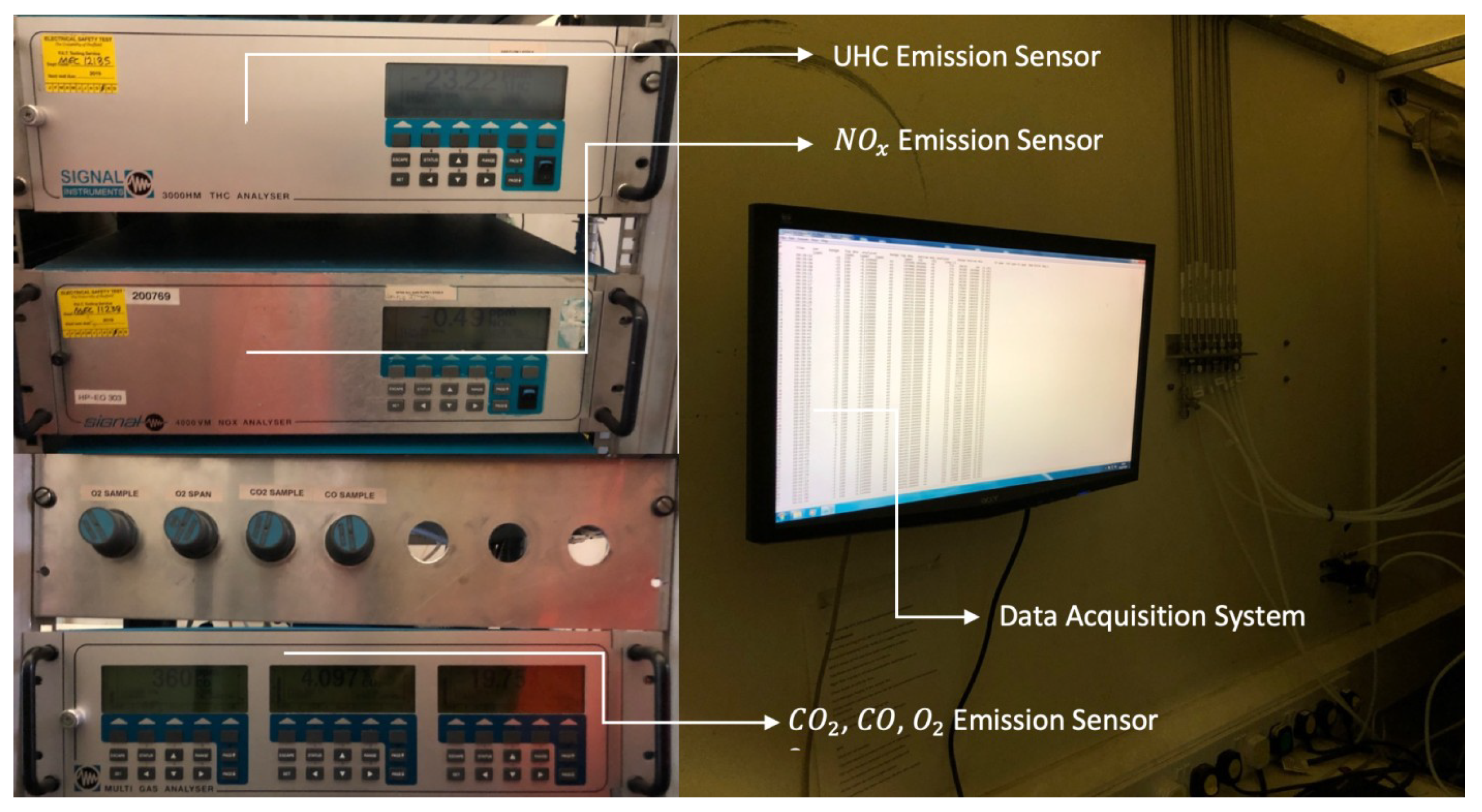
The operation of the LII-300 for PM emission measurements is straightforward. A probe connected to a pipe was attached to the exit of the testing combustor. Samples of smoke and soot were drawn through the pipe to the measuring instrument. The data collected were displayed directly on the screen, providing a live diagram of soot exhaust per unit volume over time. The accuracy and reliability of LII have been validated in numerous studies. For example, Lauer et al. (2019) conducted a comprehensive evaluation of LII techniques in various combustion systems, confirming its efficacy in measuring PM emissions accurately under different operating conditions [40]. Furthermore, the use of LII in high-pressure environments has been extensively researched, with findings indicating that it can effectively capture the rapid changes in PM concentration typical of gas turbine combustors [41]. In addition to LII, smoke measurements were also conducted using the ASTM Smoke Number (SN) method, which has been the standard for many years. However, recent studies suggest that while the SN method provides a good indication of visible smoke emissions, it may not accurately reflect the finer particulate emissions that are critical for understanding the full environmental impact of combustion processes [42].

2.4.3. UHC, N O x , C O , and C O 2 Emissions

Accurately measuring emissions of unburned hydrocarbons (UHCs), nitrogen oxides ( N O x ), carbon monoxide (CO), and carbon dioxide ( C O 2 ) is critical for evaluating the environmental impact and performance of gas turbine combustors. These measurements help in understanding combustion efficiency, identifying areas for improvement, and ensuring compliance with emission regulations.

Measurement Techniques

For this study, the instruments used to measure UHCs, N O x , CO, and C O 2 emissions included the 3000HM THC Analyser, 4000VM N O x Analyser, and a Multi-Gas Analyser (Signal Group Ltd., Camberley, Surrey, UK), as shown in Figure 9. These analysers are designed to provide precise and reliable measurements of emissions from gas turbine combustors. The 3000HM THC Analyser measures total hydrocarbons (UHCs) by utilising flame ionisation detection (FID), which is highly sensitive and capable of detecting low concentrations of hydrocarbons in the exhaust stream. The 4000VM N O x Analyser uses chemiluminescence detection (CLD) to measure N O x , providing accurate measurements essential for understanding the formation of nitrogen oxides during combustion. The Multi Gas Analyser employs non-dispersive infrared (NDIR) technology to measure CO and C O 2 concentrations, which are critical indicators of combustion efficiency and fuel utilisation [42].

Data Collection and Analysis

The emissions samples were collected from the same probe used for PM and smoke measurements, ensuring consistency in the sampling process. The collected data were displayed directly on the screen, allowing real-time monitoring and analysis of the emissions. Accurate measurement of these emissions is crucial for optimising combustor performance and reducing environmental impact. For instance, N O x emissions are primarily formed at high temperatures and are major contributors to air pollution and smog. Reducing N O x emissions is a key focus in the design of low-emission combustors. Studies by the Environmental Protection Agency (EPA) and other research bodies have shown that advanced combustion techniques, such as lean premixed combustion, can significantly reduce N O x emissions by maintaining lower flame temperatures [43]. CO emissions are typically a result of incomplete combustion and indicate inefficient fuel use. High CO emissions can signal that the combustion process needs optimisation to ensure more complete fuel burning. Research has demonstrated that optimising the air-fuel ratio and improving mixing can effectively reduce CO emissions in gas turbine engines [40]. UHC emissions result from unburned fuel escaping the combustion process, often due to poor mixing or quenching effects. Reducing UHC emissions involves improving fuel atomisation and ensuring thorough mixing of air and fuel. Advanced diagnostic techniques, such as those employed in this study, are critical for identifying the sources of UHCs and implementing design changes to mitigate these emissions [41]. C O 2 emissions are directly related to fuel consumption and are a major greenhouse gas. Measuring C O 2 emissions provides insights into the overall efficiency of the combustion process and the carbon footprint of the combustor.

2.5. Error Analysis for Experimental Instrumentations and Data Cleaning

Equipment Error: Accurate data acquisition in high-pressure combustion experiments is essential for reliable research findings. This subsection provides a detailed error analysis for the measurement systems used.
  • Temperature Measurements: Thermocouples (K-type) used in high-temperature environments have a typical error of ±1.5 °C or 0.4% of the measured temperature, whichever is greater. Regular calibration and optimal positioning reduce errors [44]. Infrared thermometers have an accuracy of ±2% of the reading or ±3 °C, whichever is greater [45].
  • Pressure Measurements: Pressure transducers used in the experiments have an accuracy of ±0.25% of full-scale reading. Vibration-damping fixtures and averaging multiple readings help minimise errors [46].
  • Airflow and Mass Flow Rate Measurements: Differential pressure sensors used for air mass flow rate measurement have an accuracy of ±1% of full-scale reading [47]. Controlled conditions for temperature and pressure ensure accurate calculations.
  • Emission Measurements: Laser-induced incandescence (LII-300) for PM emissions has an error margin of ±10% for soot volume fraction measurements [48]. The 3000HM THC Analyser (accuracy: ±1%), 4000VM N O x Analyser (accuracy: ±0.5 ppm), and Multi-Gas Analyser (accuracy: ±2%) were regularly calibrated with certified gas mixtures to prevent drift [49].
  • Data Acquisition and Processing: High-quality DAQ systems with noise filtering capabilities have an accuracy of ±0.1% of the reading. High sampling rates and data redundancy ensure accurate capture of transient phenomena [50].
Data Cleaning: The data cleaning procedures for emission measurements are crucial for ensuring the integrity and accuracy of the results. Since emissions are continuous variables, subject to fluctuations due to instability in the combustion process, it is paramount to address anomalies such as temporary blowouts in the combustion chamber, which can cause data fluctuations. Each set of combustion tests, lasting approximately 3–4 min, generated emission data that were then analysed through advanced statistical methods to detect and correct for outliers. The data cleaning process incorporated the following advanced steps:
  • Calculation of Robust Statistical Metrics:
    • Median and Interquartile Range (IQR):
      Median = median ( X ) , IQR = Q 3 Q 1
      where Q 1 and Q 3 are the 25th and 75th percentiles of the data, respectively.
  • Application of a Modified Z-Score Method:
    • Modified Z-Score for Outlier Detection:
      M i = 0.6745 × X i Median ( X ) IQR
      This method is particularly useful for datasets with skewed distributions or those susceptible to influence from extreme values.
  • Elimination of Outliers:
    • Outliers were defined as any data points where the absolute value of the modified Z-score exceeded 3.5. An illustrative example using Toluene measurements, where 140 readings of UHCs during the combustion test were analyzed, demonstrates this approach:
      M UHC = 0.6745 × UHC Median ( UHC ) IQR UHC
      Data points with | M UHC | > 3.5 were removed from the dataset.
This refined data-cleaning methodology ensures that the processed data are not only free from outliers but also retain a robust structure suitable for further analysis and interpretation. The use of median and IQR in place of mean and standard deviation mitigates the impact of extreme outliers, thus enhancing the reliability of the analytical outcomes.

3. Results and Discussion

The test conditions were established to obtain a baseline combustion and emission performance of the designed combustor using Jet−A1 fuel. This baseline serves as a reference point for subsequent tests involving Jet−A1 blended with six different aromatic species. The following table summarises the test conditions and results for the Jet−A1 baseline test.

3.1. Testing Results for Jet−A1

The Jet−A1 baseline test was conducted with a fuel inlet pressure of 9 bar and an air inlet pressure of 11 bar. The importance of the nozzle in stabilising combustion was evident in the experimental setup. Without the nozzle, the flame extended beyond the combustion chamber, resulting in an unstable internal combustion process. Conversely, with the nozzle installed, the internal pressure stabilised, and only visible smoke was emitted from the exhaust. Under these conditions, the combustor achieved a stable inner chamber pressure of 10 bar and a temperature of 1229.15 K. The mass flow rates of the air and fuel calculated based on pressure and geometric information are shown in Table 2. As shown in Figure 10, unclear smoke can be visualised and the particulate matter (PM) emissions were measured at 80 mg/m3. These baseline results demonstrate the capability of the designed combustor to maintain stable combustion and provide a consistent reference point for subsequent tests with aromatic blends. Stable combustion was visually confirmed, and no significant flame blowout or instability was observed, as illustrated in Figure 10.

Importance of Baseline Test

Establishing a baseline with Jet−A1 fuel is crucial for several reasons. Firstly, the baseline data provide a reference to compare the effects of adding different aromatic species to the fuel. Secondly, understanding the emission characteristics of Jet−A1 alone helps isolate the impact of aromatics on emissions. Thirdly, the baseline ensures that the combustor operates within safe and stable limits, which is essential for reliable comparative analysis. Following the baseline test, six different aromatic species were blended with Jet−A1 to evaluate their impact on combustion performance and emissions. Each aromatic blend was tested under similar conditions to those of the baseline to ensure comparability. These tests aim to identify how different aromatic hydrocarbons influence the emission of pollutants and the overall efficiency of the combustor. The detailed results of these tests will be presented in subsequent sections, highlighting the comparative analysis between the baseline and aromatic blends.

3.2. Testing Results for Jet−A1 Blended with Different Aromatic Species

3.2.1. Particulate ( P M ) Emission Results

After confirming the settings for the air and fuel inlet, a series of combustion tests were conducted using different types of aromatic hydrocarbons. The particulate matter (PM) emission results are summarised in Table 3.
The combustion conditions for all aromatic hydrocarbons were maintained consistently to ensure comparability of the results. As shown in Table 3, all aromatic blends produced significantly lower PM emissions compared to the baseline Jet−A1 fuel under the same combustion conditions. Notably, the combustion of O−Xylene resulted in the highest inner chamber temperature while generating the least PM emissions. Further analysis of the experimental data revealed the following relationships between various variables.
  • Temperature and PM Emissions: A clear trend was observed where the combustion temperature influenced the PM emissions. As shown in Table 3, Toluene combustion, which had the lowest temperature, resulted in the highest PM emissions. Conversely, O−Xylene combustion, with the highest temperature, produced the lowest PM emissions. This inverse relationship suggests that higher combustion temperatures enhance the completeness of combustion, thereby reducing soot formation and PM emissions.
  • Potential Impact of Aromatic Structure: The structure of the aromatic hydrocarbons significantly affects the emission outcomes. Studies have shown that the molecular structure of aromatics influences their combustion behaviour and the formation of soot particles. For instance, aromatic compounds with more rings and higher molecular weights tend to produce more soot [11]. One explanation for this phenomenon is that lower aromatic content in the fuel reduces the formation of soot precursors. Aromatic compounds are known to be significant contributors to soot formation due to their ring structures, which promote the polymerisation processes that form soot particles. The production decreases when the aromatic content is reduced or modified to include species less prone to soot formation. This is particularly evident with synthetic paraffinic kerosene (SPK) blends, which have been shown to reduce PM emissions due to their lower aromatic content and more complete combustion properties [31]. Furthermore, the specific types of aromatic species used in the blend play a crucial role. Not all aromatics contribute equally to soot formation; some have higher sooting tendencies than others. The overall PM emissions can be significantly reduced by selecting aromatic species with lower sooting propensities for blending. This selective blending improves combustion efficiency and helps achieve cleaner exhaust emissions, aligning with environmental regulations and standards.
  • Role of Fuel Composition: The 13% mass blend composition of the aromatic species with Jet−A1 also plays a critical role in emission characteristics. The presence of aromatic compounds could alter the chemical kinetics of the combustion process, affecting the formation of intermediate species that lead to soot and PM. The findings align with those reported in the literature, where specific aromatic contents in fuel blends have been linked to variations in emission profiles [51].
The test results indicate that blending Jet−A1 with different aromatic species can significantly influence the emission characteristics of the combustor. Higher combustion temperatures generally result in lower PM emissions, highlighting the potential for optimising fuel composition and combustion conditions to achieve cleaner combustion. The detailed analysis provides valuable insights for developing low-emission gas turbine combustors and improving overall combustion efficiency.

3.2.2. UHC, N O x , C O , and C O 2 Emission Results

The unburned hydrocarbon (UHC), N O x , C O , and C O 2 emissions were monitored using a probe connected to the nozzle exit of the combustion chamber. Real-time data for these emissions were recorded every two seconds. The cleaned and final experimental results are detailed below.
The emission results of UHC, N O x , C O , and C O 2 for different types of aromatic hydrocarbons indicate that the fuel type substantially impacts the emission rates. Observed C O 2 levels, reported in ppm rather than higher volume fractions, can be attributed to the high sensitivity of the measurement instruments and the potential for incomplete combustion, particularly with certain aromatic hydrocarbon blends, as evidenced by elevated C O emissions. These variations in emission levels reflect the combustion efficiency and specific conditions during the tests. Based on the current data, further studies will be conducted to enhance the performance and accuracy of the custom-built combustor, aiming to further optimise combustion efficiency and minimise emissions.
  • U H C 
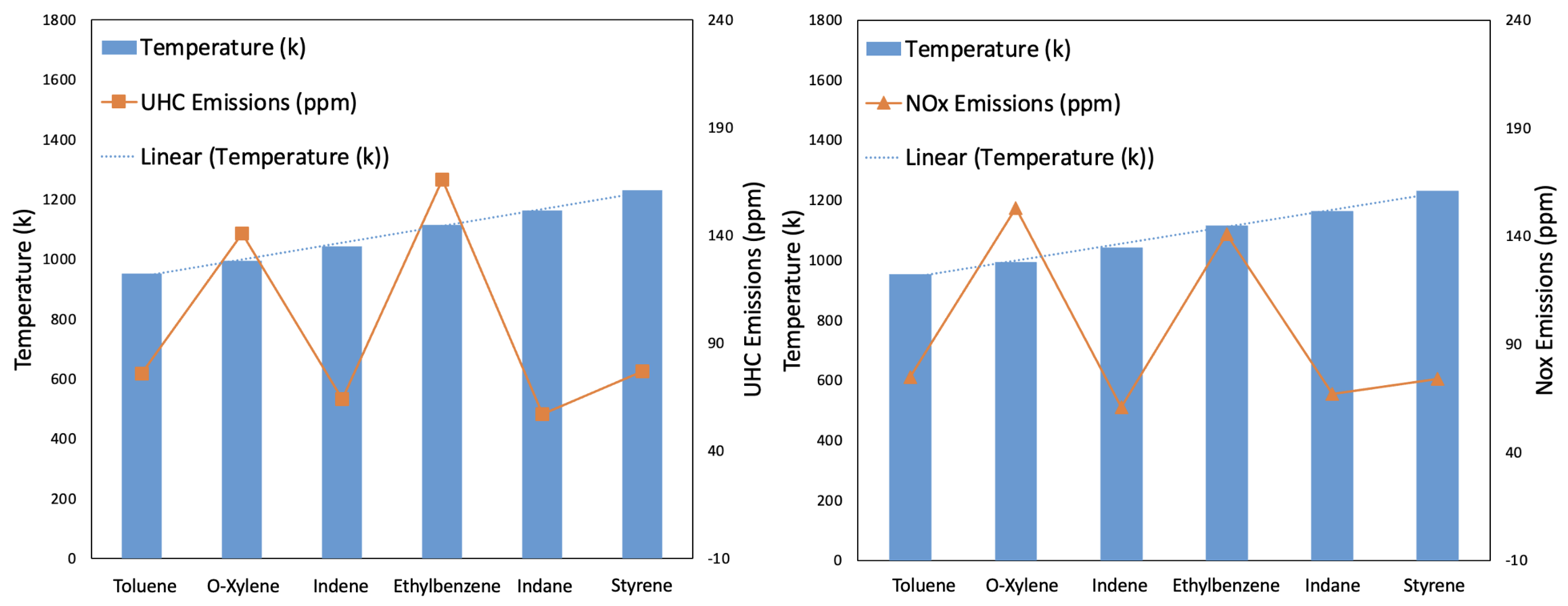
Emissions: As shown in Figure 11, Ethylbenzene produced the highest UHC emissions, while Indane produced the lowest. This variation indicates that the chemical structure and properties of the aromatic hydrocarbons significantly influence the formation of unburned hydrocarbons.
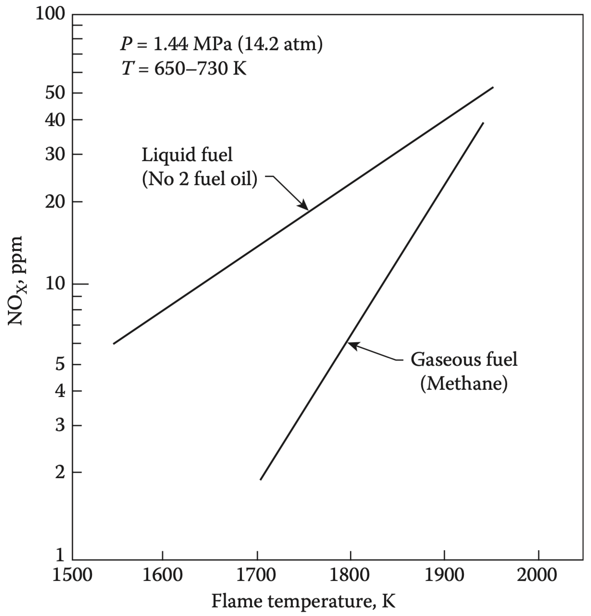
  • N O x Emissions: For N O x emissions, Indane again produced the least amount, whereas O−Xylene produced the highest. N O x formation is highly temperature-dependent, and the combustion temperature profiles indicate that variations in aromatic structure can lead to different thermal N O x formation rates [2]. Higher combustion temperatures generally increase N O x emissions due to the enhanced nitrogen and oxygen reaction rates [43].
  • C O Emissions: Figure 12 reveals that C O emissions were relatively high for Ethylbenzene and low for Indane. High C O emissions typically indicate incomplete combustion, where insufficient oxygen or inadequate mixing prevents the complete oxidation of carbon to C O 2 . The variation in CO emissions across different aromatics suggests differences in combustion efficiency and fuel oxidation processes [11].
  • C O 2 Emissions:  C O 2 emissions were found to be almost the same across different aromatics, with Ethylbenzene having the highest and Indane having the lowest emissions. C O 2 is a primary combustion product, and its consistent levels across different fuels suggest that, despite variations in intermediate species like C O and UHC, the overall carbon conversion to C O 2 remains fairly constant. This could imply a similar level of overall combustion efficiency across the tested aromatic fuels, albeit with different pathways and intermediate stages [41].
It is clear from Figure 11 and Figure 12 that the emission profiles for different aromatic hydrocarbons show significant variation. Notably, O−Xylene and Ethylbenzene generated the highest emissions for UHC, N O x , C O , and C O 2 . This consistency suggests a strong correlation between the chemical properties of the aromatic hydrocarbons and their emission rates.
  • Chemical Structure: The molecular structure of aromatics, including ring number and substituents, influences the combustion process and emission formation. More complex structures may lead to higher emissions due to incomplete combustion and soot formation;
  • Combustion Temperature: Higher combustion temperatures generally reduce UHC and C O emissions but increase N O x emissions. This inverse relationship underscores the importance of optimising combustion conditions to balance the reduction of all pollutants;
  • Fuel Blending: The proportion of aromatics in the fuel blend affects the emission profile. Due to incomplete oxidation, Higher aromatic content could increase soot and UHC emissions.
The results indicate that blending Jet−A1 with different aromatic species significantly impacts the emission characteristics of the combustor. Understanding these impacts is crucial for developing strategies to reduce emissions and improve combustion efficiency. Further research should focus on optimising aromatic content and combustion conditions to reduce emissions across all pollutants.

4. Conclusions

This research successfully achieved the objectives set out at the beginning. A custom-built combustor was designed and manufactured at the Low Carbon Combustion Centre (LCCC) of the University of Sheffield. Six types of fuel blends with different aromatic hydrocarbons, in addition to Jet−A1 fuel, were tested in the custom-designed high-pressure combustor. The key findings and potential future work are summarised in the following.
Based on the experimental findings in the custom-built combustor, a clear negative correlation was observed between combustion temperature and PM emissions. Higher combustion temperatures generally resulted in lower PM emissions, indicating more complete combustion and reduced soot formation. This finding aligns with previous research showing that higher combustion temperatures enhance oxidation reactions, thereby reducing the amount of unburned carbon and soot formation [6,52].
The emission profiles for UHC, N O x , C O , and C O 2 were measured from the designed combustor. No direct relationship was found between combustion temperature and the emissions of UHC, N O x , C O , and C O 2 . Significant variations in emissions were observed when different aromatic hydrocarbons were applied, suggesting a strong correlation between the chemical characteristics of the fuel and the emission rates. Among different aromatics tested, O−Xylene and Ethylbenzene produced the highest amounts of UHC, N O x , C O , and C O 2 emissions, which can be attributed to their higher molecular weights and complex structures that resist complete combustion. Conversely, Indane produced the lowest emissions for these pollutants, indicating more complete combustion.
In conclusion, the experimental findings are consistent with established combustion theory, where higher combustion temperatures enhance oxidation rates, leading to lower PM emissions. The emission profiles of UHC, N O x , C O , and C O 2 are influenced by the chemical structure and reactivity of the fuel, with more stable aromatic hydrocarbons exhibiting higher emissions due to incomplete combustion processes. Further theoretical and computational studies could provide deeper insights into the specific reaction pathways and intermediate species formation, enhancing the interpretation of these experimental results.

Author Contributions

Conceptualization, Q.Y.; Data curation, Q.Y.; Writing—original draft, Q.Y.; Writing—review & editing, Q.Y. and B.K.; Project administration, B.K. All authors have read and agreed to the published version of the manuscript.

Funding

This research received no external funding.

Data Availability Statement

No additional data are available.

Acknowledgments

The authors would like to extend their heartfelt thanks to the technicians and other research students at the Low Carbon Combustion Centre (LCCC) for their invaluable assistance in manufacturing the high-pressure combustor and the V-shaped baffle plate. Their expertise and dedication were crucial to the success of this research project.

Conflicts of Interest

The authors declare no conflicts of interest.

References

  1. Federal Aviation Administration. Aviation Emissions, Impacts & Mitigation: A Primer. Available online: https://www.faa.gov/sites/faa.gov/files/regulations_policies/policy_guidance/envir_policy/Primer_Jan2015.pdf (accessed on 2 March 2019).
  2. Lefebvre, A.; Ballal, D. Gas Turbine Combustion, 3rd ed.; CRC Press: Boca Raton, FL, USA, 2010. [Google Scholar]
  3. Saravanamuttoo, H. Gas Turbine Theory, 7th ed.; Licensing Agency Ltd.: London, UK, 2017. [Google Scholar]
  4. Jones, W.P.; Lindstedt, R.P. Global reaction schemes for hydrocarbon combustion. Combust. Flame 2008, 152, 170–195. [Google Scholar] [CrossRef]
  5. Ballal, D.R.; Lefebvre, A.H. Weak extinction limits of turbulent flowing mixtures. J. Eng. Power 1979, 343–348. [Google Scholar] [CrossRef]
  6. Turns, S.R. An Introduction to Combustion: Concepts and Applications, 2nd ed.; McGraw-Hill: New York, NY, USA, 2000. [Google Scholar]
  7. Nathanson, J.A. Greenhouse Gases. Encyclopedia Britannica. 2019. Available online: https://www.britannica.com/science/air-pollution/Greenhouse-gases (accessed on 16 March 2019).
  8. Energy UK. Environmental Regulations. Available online: https://www.energy-uk.org.uk/insights/electricity-generation/ (accessed on 16 March 2019).
  9. Tikuisis, P.; Kane, D.; McLellan, T.; Buick, F.; Fairburn, S. Rate of formation of carboxyhemoglobin in exercising humans exposed to carbon monoxide. J. Appl. Physiol. 1992, 72, 1311–1319. [Google Scholar] [CrossRef] [PubMed]
  10. Connellan, S. Lung diseases associated with hydrocarbon exposure. Respir. Med. 2017, 126, 46–51. [Google Scholar] [CrossRef]
  11. Zheng, L.; Singh, P.; Cronly, J.; Ubogu, E.A.; Ahmed, I.; Ling, C.; Zhang, Y.; Khandelwal, B. Impact of aromatic structures and content in formulated fuel for jet engine applications on particulate matter emissions. J. Energy Resour. Technol. 2021, 143, 122301. [Google Scholar] [CrossRef]
  12. Almohammadi, B.A.; Singh, P.; Sharma, S.; Kumar, S.; Khandelwal, B. Experimental investigation and correlation development for engine emissions with polycyclic aromatic blended formulated fuels. Fuel 2021, 303, 121280. [Google Scholar] [CrossRef]
  13. Chapman, J.; Singh, P.; Kumar, S.; Khandelwal, B. Optimization of aromatic species in formulated fuel for simultaneous reduction of PM and NOx emissions from combustion engines. J. Energy Inst. 2022, 103, 94–103. [Google Scholar] [CrossRef]
  14. Singh, P.; Khandelwal, B.; Almohammadi, B.A.; Sharma, S.; Kumar, S. Investigations on combustion and emissions characteristics of aromatic fuel blends in a distributed combustor. Fuel Process. Technol. 2021, 208, 106548. [Google Scholar]
  15. Dandajeh, H.A.; Talibi, M.; Ladommatos, N. Polycyclic aromatic hydrocarbon and soot emissions in a diesel engine and from a tube reactor. J. King Saud Univ.-Eng. Sci. 2022, 65, 435–444. [Google Scholar] [CrossRef]
  16. Talibi, M.; Hellier, P.; Ladommatos, N. Impact of increasing methyl branches in aromatic hydrocarbons on diesel engine combustion and emissions. Fuel 2018, 216, 579–588. [Google Scholar] [CrossRef]
  17. Chu, H.; Qi, J.; Feng, S.; Dong, W.; Hong, R.; Qiu, B.; Han, W. Soot formation in high-pressure combustion: Status and challenges. Fuel 2023, 345, 128236. [Google Scholar] [CrossRef]
  18. Liu, P.; Guo, J.J.; Quadarella, E.; Bennett, A.; Gubba, S.R. The effect of preheating temperature on PAH/soot formation in methane/air co-flow flames at elevated pressure. Fuel 2022, 313, 122656. [Google Scholar] [CrossRef]
  19. Kalvakala, K.C.; Aggarwal, S.K. PAHs and soot emissions in oxygenated ethylene diffusion flames at elevated pressures. In Proceedings of the ASME Turbo Expo: Power for Land, Sea, and Air, Oslo, Norway, 11–15 June 2018. [Google Scholar] [CrossRef]
  20. Liang, S.; Li, Z.; Gao, J.; Ma, X.; Xu, H.; Shuai, S. PAHs and soot formation in laminar partially premixed co-flow flames fuelled by PRFs at elevated pressures. Combust. Flame 2019, 206, 363–378. [Google Scholar] [CrossRef]
  21. Braun-Unkhoff, M.; Kathrotia, T.; Rauch, B.; Riedel, U. About the interaction between composition and performance of alternative jet fuels. CEAS Aeronaut. J. 2016, 7, 83–94. [Google Scholar] [CrossRef]
  22. Xue, X.; Hui, X.; Singh, P.; Sung, C.J. Soot formation in non-premixed counterflow flames of conventional and alternative jet fuels. Fuel 2017, 210, 343–351. [Google Scholar] [CrossRef]
  23. Lobo, P.; Christie, S.; Khandelwal, B.; Blakey, S.G.; Raper, D.W. Evaluation of Non-volatile Particulate Matter Emission Characteristics of an Aircraft Auxiliary Power Unit with Varying Alternative Jet Fuel Blend Ratios. Energy Fuels 2015, 29, 7705–7711. [Google Scholar] [CrossRef]
  24. Silverman, B. Effects of High Aromatic Aviation Fuel on Sealant Systems. SAE Tech. Pap. 1980, 89, 2646–2650. [Google Scholar]
  25. Chen, K.; Liu, H.; Xia, Z. The Impacts of Aromatic Contents in Aviation Jet Fuel on the Volume Swell of the Aircraft Fuel Tank Sealants. SAE Int. J. Aerosp. 2013, 6, 350–354. [Google Scholar] [CrossRef]
  26. Hamilton, J.; Khandelwal, B. Effects of Aromatic Blends on Seal Swell Rates Using Novel Seals Compatibility Test Rig. In Proceedings of the AIAA SCITECH 2023 Forum, National Harbor, MD, USA, 23–27 January 2023; p. 0596. [Google Scholar]
  27. Anuar, A.; Undavalli, V.K.; Khandelwal, B.; Blakey, S. Effect of fuels, aromatics and preparation methods on seal swell. Aeronaut. J. 2021, 125, 1542–1565. [Google Scholar] [CrossRef]
  28. Khandelwal, B.; Roy, S.; Lord, C.; Blakey, S. Comparison of vibrations and emissions of conventional jet fuel with stressed 100% SPK and fully formulated synthetic jet fuel. Aerospace 2014, 1, 52–66. [Google Scholar] [CrossRef]
  29. Ruslan, M.; Ahmed, I.; Khandelwal, B. Evaluating Effects of Fuel Properties on Smoke Emissions. In Proceedings of the ASME Turbo Expo 2016: Turbomachinery Technical Conference and Exposition, Seoul, Republic of Korea, 13–17 June 2016; p. V04AT04A046. [Google Scholar] [CrossRef]
  30. Leach, F.; Chapman, E.; Jetter, J.J.; Rubino, L.; Christensen, E.D.; St. John, P.C.; Fioroni, G.M.; McCormick, R.L. A review and perspective on particulate matter indices linking fuel composition to particulate emissions from gasoline engines. SAE Int. J. Fuels Lubr. 2022, 15, 3–28. [Google Scholar] [CrossRef]
  31. Schripp, T.; Anderson, B.E.; Bauder, U.; Rauch, B.; Corbin, J.C.; Smallwood, G.J.; Lobo, P.; Crosbie, E.C.; Shook, M.A.; Miake-Lye, R.C.; et al. Aircraft engine particulate matter emissions from sustainable aviation fuels: Results from ground-based measurements during the NASA/DLR campaign ECLIF2/ND-MAX. Fuel 2022, 325, 124764. [Google Scholar] [CrossRef]
  32. Tian, B.; Liu, A.; Chong, C.T.; Fan, L.; Ni, S.; Hull, A.; Rigopoulos, S.; Luo, K.H.; Hochgreb, S. Measurement and simulation of sooting characteristics by an ATJ-SKA biojet fuel and blends with Jet A-1 fuel in laminar non-premixed flames. Combust. Flame 2021, 233, 111582. [Google Scholar] [CrossRef]
  33. Durdina, L.; Brem, B.T.; Elser, M.; Schonenberger, D.; Siegerist, F.; Anet, J.G. Reduction of nonvolatile particulate matter emissions of a commercial turbofan engine at the ground level from the use of a sustainable aviation fuel blend. Environ. Sci. Technol. 2021, 55, 14576–14585. [Google Scholar] [CrossRef] [PubMed]
  34. Heeb, N.V.; Munoz, M.; Haag, R.; Wyss, S.; Schoonenberger, D.; Durdina, L.; Elser, M.; Siegerist, F.; Mohn, J.; Brem, B.T. Corelease of Genotoxic Polycyclic Aromatic Hydrocarbons and Nanoparticles from a Commercial Aircraft Jet Engine–Dependence on Fuel and Thrust. Environ. Sci. Technol. 2024, 58, 1615–1624. [Google Scholar] [CrossRef] [PubMed]
  35. Longwell, J.P.; Chenevey, J.E.; Clark, W.W.; Frost, E.E. Flame Stabilization by Baffles in a High Velocity Gas Stream. Symp. Combust. Flame Explos. Phenom. 1984, 3, 40–44. [Google Scholar] [CrossRef]
  36. National Aerospace Laboratory. Design and Development of a High-Pressure Combustor for Aero Engines. ASME Digit. Collect. 2014, 100, 129–140. [Google Scholar]
  37. Baxter, M.R.; Lefebvre, A.H. Weak Extinction Limits of Large Scale Flame-holders. J. Eng. Gas Turbines Power 1991, 114, 776–782. [Google Scholar] [CrossRef]
  38. Environmental Protection Agency. Polycyclic Aromatic Hydrocarbon Emissions from the Combustion of Alternative Fuels in a Gas Turbine Engine. Available online: https://www.researchgate.net/publication/224848815_Polycyclic_Aromatic_Hydrocarbon_Emissions_from_the_Combustion_of_Alternative_Fuels_in_a_Gas_Turbine_Engine (accessed on 16 March 2019).
  39. Gianinoni, I.; Rossi, A.; Villani, L. Optical Probe for the Turbine Inlet Temperature Measurement in Gas Turbine Plants. J. Eng. Gas Turbines Power 2020, 142, 450–459. [Google Scholar]
  40. Lauer, J.; Krause, S.; Will, S. Laser-Induced Incandescence for Soot Measurement: Recent Developments and Applications. Appl. Phys. B 2019, 125, 116. [Google Scholar]
  41. Santoro, R.J.; Shaddix, C.R. Laser-induced incandescence. Appl. Combust. Diagn. 2002, 26, 252–286. [Google Scholar]
  42. GE Vernova. Gas Turbine Emissions and Control. Available online: https://www.gevernova.com/content/dam/gepower-new/global/en_US/downloads/gas-new-site/resources/reference/ger-4211-gas-turbine-emissions-and-control.pdf (accessed on 16 March 2019).
  43. Environmental Protection Agency. Emission Standards for Stationary Gas Turbines. Available online: https://www.epa.gov/stationary-sources-air-pollution/stationary-gas-and-combustion-turbines-new-source-performance (accessed on 18 May 2019).
  44. Thermocouple Product Information. Available online: https://www.omega.com/prodinfo/thermocouples.html (accessed on 18 May 2024).
  45. Infrared Thermometer Specifications. Available online: https://www.thermoworks.com/ (accessed on 18 May 2024).
  46. Pressure Transducer Product Information. Available online: https://www.omega.com/prodinfo/pressuretransducers.html (accessed on 19 May 2024).
  47. Differential Pressure Sensors. Available online: https://www.omega.com/en-us/ (accessed on 20 May 2024).
  48. Laser-Induced Incandescence Information. Available online: https://www.combustioninstitute.org/news-and-events/news/ (accessed on 20 May 2024).
  49. Emissions Measurement Instruments. Available online: https://www.horiba.com/int/ (accessed on 20 May 2024).
  50. Data Acquisition Systems. Available online: https://www.ni.com/en-us/shop/data-acquisition.html (accessed on 20 May 2024).
  51. Hileman, J.I.; Ortiz, D.S.; Bartis, J.T.; Wong, H.M.; Donohoo, P.E.; Weiss, M.A.; Waitz, I.A. Near-Term Feasibility of Alternative Jet Fuels; Rand Corporation: Los Angeles, CA, USA, 2009. [Google Scholar]
  52. Ruan, R.; Wang, X.; Li, J.; Cui, B.; Lyu, Z.; Wang, X.; Tan, H. The effect of preheating temperature and combustion temperature on the formation characteristics of PM0.4 from preheating combustion of high-alkali lignite. Fuel 2023, 348, 128560. [Google Scholar] [CrossRef]
Figure 1. N O x vs. flame temperature [2].
Energies 17 03939 g001
Figure 2. Six selected aromatic species chemical structures [11].
Energies 17 03939 g002
Figure 3. Fuel atomiser design and tests.
Energies 17 03939 g003
Figure 4. Designed high-pressure combustor with a V-shaped baffle plate as flame stabiliser (Unit: mm).
Energies 17 03939 g004
Figure 5. Manufactured high-pressure combustor.
Energies 17 03939 g005
Figure 6. Initial CFDsimulations based on ANSYS CFD.
Energies 17 03939 g006
Figure 7. Temperature and pressure sensors.
Energies 17 03939 g007
Figure 8. Live air mass flow rate measuring instrument.
Energies 17 03939 g008
Figure 9. UHC, N O x , C O , and C O 2 measuring instruments.
Energies 17 03939 g009
Figure 10. Initial Jet−A1 tests with visible smoke.
Energies 17 03939 g010
Figure 11. UHC and N O x emission results (Jet−A1 with different aromatic species (13% mass blend)).
Energies 17 03939 g011
Figure 12. C O and C O 2 emission results (Jet−A1 with different aromatic species (13% mass blend)).
Energies 17 03939 g012
Table 1. Fuel preparation.
FuelChemical FormulaAuto Ignition Temp. (K)
Toluene C 7 H 8 753.15
O−Xylene C 8 H 10 1140.15
Styrene C 6 H 5 C H = C H 2 763.15
Ethylbenzene C 6 H 5 C 2 H 5 705.15
Indene C 9 H 8 /
Indane C 9 H 10 /
Table 2. Baseline testing conditions.
Air Mass Flow Rate (kg/s)Fuel Mass Flow Rate (kg/s)Environmental Temperature (K)
∼0.0209∼0.00042∼300
Table 3. Testing results: particulate ( P M ) emission.
Aromatic Type T Inner (°C) P M (mg/m3)
Toluene952.7–954.728–30
O-Xylene1204.95–1257.356–7
Styrene987.85–1002.4512–14
Ethylbenzene999.45–1231.8510–11
Indene989.45–1096.3515–16
Indane1130.75–1196.7511–12
Disclaimer/Publisher’s Note: The statements, opinions and data contained in all publications are solely those of the individual author(s) and contributor(s) and not of MDPI and/or the editor(s). MDPI and/or the editor(s) disclaim responsibility for any injury to people or property resulting from any ideas, methods, instructions or products referred to in the content.

