Abstract
With the explosion in energy consumption demand, the deep penetration of renewable energy into the grid is inevitable and has become trend across the world today. Microgrids with integrated renewable energy are the core components of smart grids and will permeate all areas of human activity. Although this grid has a very flexible working principle, its heavy reliance on renewable energy sources can cause significant disturbances to the electric transmission system. Therefore, the control and monitoring processes for microgrids must be implemented through various mechanisms to ensure the microgrid system operates safely, stably, and effectively. In this paper, the research team will introduce and synthesize the multilevel control scheme of current types of microgrids. We will evaluate the advantages and disadvantages of each type of MG, providing a reference for further research in the field of microgrid control applications, both current and in the near future.
1. Introduction
All nations around the globe depend heavily on electrical power, and guaranteeing the security and reliability of this power is crucial to modern industry and daily living. Electrical power is an urgent necessity due to the world’s constantly expanding population, the eventual replacement of outdated industries with green energy, the depletion of fossil fuels, and the modern world’s reliance on electrical power. Reducing greenhouse gas emissions has become a crucial subject for all countries, as developed industries largely depend on electricity. This also contributes to a sustainable economy. Consequently, renewable and ecological energy sources will inevitably become more popular in the future as fossil fuels, which harm the environment and cause pollution, are gradually phased out.
The utilization of renewable energy sources (RESs), such as wind [1,2], photovoltaic (PV) panels [3], ocean energy [4], hydrogen [5], flywheels [6], and potentially geothermal energy [7], is both necessary and beneficial. These energy sources can generate electrical power that can be used locally or integrated with the current transmission grid to transmit power over long distances with the right control arrangements.
When a power transmission line does not pass, a grid that incorporates renewable power can be thought of as a type of microgrid (MG). These MGs combine RESs with existing energy sources (such as diesel, thermal power, etc.) to provide a suitable means of supplying isolated households, community groups, or residential areas. Due to the instability of RESs, which rely heavily on natural conditions, MGs that integrate them must consider how their input power may be influenced. Therefore, a central control system with flexible control solutions is required to manage local power control and transmission for MGs operating in the islanded or grid mode. This system must also facilitate steady and equitable grid mode operations while enabling long-distance power transport.
Control strategies used in MGs are not novel ideas. Numerous studies, as discussed in [8,9], have explored control solutions specifically applied to DC microgrid (DCMG) controllers. These studies include both classic and advanced control methods in scenarios where the controllers are connected to the grid or operating in the islanded mode. Furthermore, AC microgrids (ACMGs) are also examined in detail, much like DCMGs [10].
Additionally, some intelligent controller applications for MGs are addressed in [11], including hybrid adaptive algorithms, intelligent algorithms such as Particle Swarm Optimization (PSO), Fuzzy Logic Control (FLC), and Neutral Network (NN), as well as algorithms like Proportional–Integral–Derivative (PID), Linear Quadric Regulator (LQR), and Sliding Mode Control (SMC). Beyond general control strategies for MGs, direct studies are being conducted for MG development in nations like the US, EU countries, and China [12].
The most recent advances in circuit architecture, control techniques, and fault tolerance strategies for Modular Multilevel Converters (MMCs) in MG applications have also been discussed by the authors of this work. MMCs are intermediary devices with a diverse structure, exceptional characteristics, and notable restrictions that can be seamlessly integrated with existing renewable energy sources, such as PV solar, wind turbines, and battery energy storage systems (BESSs). The research team has thoroughly presented the mechanism to assess the power converter’s function in current MGs [13]. Microgrid concepts, the history of their formation and development in recent years, the research team’s objective, specific and historical perspective on topology, as well as the process of control and communication through the network by analyzing prior research findings are among the key issues addressed in this study. Another important focus is the current approach to maintaining a stable, functional grid system in terms of both the voltage capacity and frequency of the MG [14].
The study group assessed several aspects of the MG system and investigated ways to help enhance the microgrid functionality and stabilization by implementing distributed control in the power grid more effectively. General references for ACMGs are provided in [15].
Based on a survey of reference materials, it is evident that the diversity and depth of control available for microgrids are currently the topics of many studies [14], as Table 1 illustrates.

Table 1.
Some reviews of studies of MGs.
An impartial and detailed evaluation of the control techniques used in DCMGs is presented in this article. Although the methods are thorough, precise, and exhaustive, they focus exclusively on DCMGs [16]. Numerous items pertaining to MG have been mentioned in the reviews above. While these studies are highly specialized and in-depth, they only address a small portion of the broader field of MGs, necessitating a more comprehensive review. Both ACMGs and DCMGs can benefit from various control strategies. We will explore these issues in greater detail in the following section.
Figure 1 provides a general summary of the MG model. Since MGs provide on-site power supply, their role as distributed generators (DGs) is vital to the construction of a potential smart grid network. They can also absorb active power or inject reactive power into the grid and release local power sources at various points through flexible control and system monitoring.
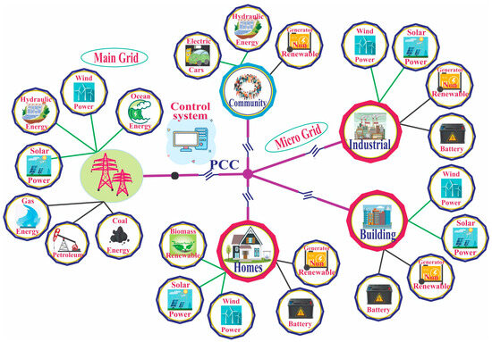
Figure 1.
General model of MGs with an integrated unity grid.
Regarding the multilevel control scheme in MGs, there are numerous techniques that vary depending on the operating method and functioning mechanism of the various types of microgrids, including DCMGs, ACMGs, and hybrid MG [17]. The content of this paper will mainly valuate and clearly classify the controllers and control modes for each different type of MG and have a clear evaluation based on the advantages and disadvantages of each method. However, to clearly understand the nature of MGs, Section 2 will cover the concept, classification of the power grid, and working mechanisms. The main content, focusing on modern control methods of MGs will be discussed in Section 3. Section 4 will summarize the research content, Section 5 will explore trends and the future of MGs, and Section 6 will conclude this paper, presenting the issues of the researched content.
2. MG Structure and Operation [18]
Although there are many concepts associated with MGs, the fundamental idea is that an MG is made up of loads and linked on-site power plants that can function separately from the electrical grid (known as islanded mode) or in connection with it (known as grid mode). Unlike previous conventional power systems, it may not be necessary to have a power transmission infrastructure because power plants can be situated close to loads. To comprehend the fundamental elements of MGs, consider the following basic categories.
Although there are many different classification methods for MGs [19], as shown in Figure 2, they can be understood simply in terms of their implementation: the source supplying the load can be AC power, DC power, or hybrid power.
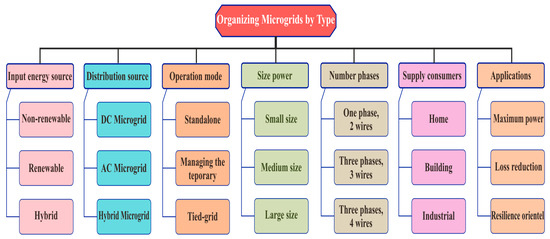
Figure 2.
Organizing microgrids by type.
2.1. AC Microgrid [10]
As the name implies, this type of power grid supplies electricity for AC loads. Although the initial power source may be DC, it must be converted to AC power. AC power can also originate from various distributed sources. This type of power grid can operate independently [20] in the event of an issue and is additionally monitored and managed through an integrated control system. This system is connected to the transmission grid via the Point of Common Coupling (PCC), which impacts the grid before supplying power to the load.
In an ACMG, the main source, DC-AC converter, and AC load are all included. Additionally, the system is connected to the grid through the PCC and a central controller, which monitors and regulates the primary sources and processes for islanded or grid mode operations. The future of power systems will inevitably see an accelerated integration of RESs into this AC grid. The ACMG diagram is shown in Figure 3.
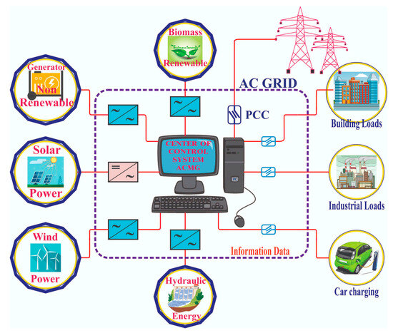
Figure 3.
Model of an ACMG.
2.1.1. The Advantages of ACMGs
Their versatility stems from their ability to be integrated into standard utility grids or used in the islanded mode. The system is easily powered by AC power supplied from the MG and is compatible with AC devices, including AC-based loads, like motors; AC loads do not require an inverter, making power protection solutions more affordable. Additionally, AC loads typically require more power.
2.1.2. The Drawbacks of ACMGs
Reduced conversion efficiency; costly inverters, such as DC-AC converters; and unbalanced compensation, voltage regulation, and frequency considerations make control difficult. Devices that require a sufficient amount of power to meet high-performance requirements may perform worse if the power supply is less reliable; compared to DC power, transmission efficiency is lower.
2.2. DCMG [21]
A DCMG will have the same system components as an ACMG, including a power supply, load, monitoring control system, and other components (Figure 4). The primary distinction lies in the type of power used; the load is powered by DC electricity. The AC supply must be rectified before connecting to the DCMG and RESs. DCMGs have lower transmission losses and are therefore better suited for long-distance power transmission because they are not affected by a Fuco current. Furthermore, when linked to the grid, DC power is simpler to use because the voltage value corresponding to the source can be adjusted without altering the frequency, phase angle, or the system’s reactive and active powers.
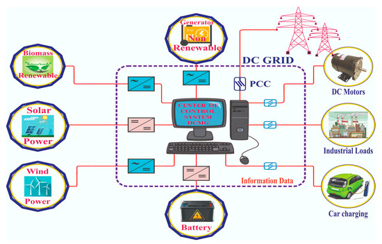
Figure 4.
Model of a DCMG.
2.2.1. The Advantages of DCMGs
The synchronization requirements for DC power are simpler than those for AC power. To compensate for changes in power generation and demand, energy storage devices can be added to the DCMG. Harmonics, voltage decreases or increases, and phase voltage asymmetry have no effect on the load. Generators, single-phase loads, and current surges during inductive switching do not impact on the voltage quality. Compared to ACMGs, DCMGs are more efficient.
2.2.2. The Drawbacks of DCMGs
Incomplete power protection systems in DCMGs may pose a problem, particularly in areas with sensitive power loads. The increased initial outlay could hinder implementation. Compared to AC grids, DCMGs are less well-known in the market. There is reduced AC load compatibility, especially considering the prevalence of of AC-based loads. Without a reactive power source, voltage drops are more likely to occur, particularly in larger systems. Additionally, converting AC to DC power increases complexity and expense.
2.3. Hybrid MGs
A hybrid MG is an energy source system that combines several sources with power generation and storage technologies to produce dependable and sustainable electricity. Unlike conventional MGs that rely on a single energy source, such as solar or wind, hybrid MGs incorporate multiple RESs, storage devices, and conventional fossil fuel-powered generators to ensure a continuous power supply.
With the development of hybrid MGs, RESs are increasingly integrated into the power grid, providing customers with a diverse range of power source options. The flexibility and safety of this type of power grid are demonstrated when a voltage drop occurs, as converters quickly engage to support stored energy sources, such as batteries, flywheels, and supercapacitors. The inverter is adjusted to balance the voltage and active power of the main source [22]. Figure 5 illustrates the connection diagram of the hybrid MG, showing how the output is processed through the inverter to supply to the load.
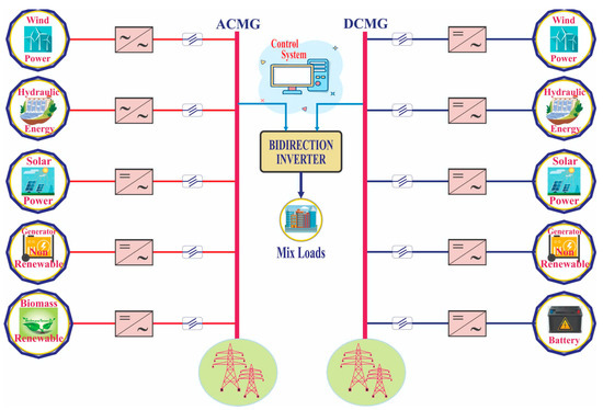
Figure 5.
Hybrid MG model.
The Benefits of Hybrid MGs [23]
Enhanced reliability: Hybrid MGs guarantee a dependable power supply, even in the event of grid failures or fluctuations in availability by combining multiple energy sources and storage technologies with renewable energy production [24,25]. Increased energy efficiency: smart control systems in hybrid MGs enable the optimal use of available energy sources, reducing waste and maximizing overall energy efficiency. Decreased carbon emissions: by integrating RESs, hybrid MGs will contribute to a cleaner and more sustainable energy future by lowering greenhouse gas emissions. Financial savings: hybrid microgrids can help reduce energy costs by optimizing the use of RESs and decreasing reliance on expensive fossil fuel generators.
2.4. The Operating Modes of MGs
2.4.1. Islanded Mode
Managing MGs becomes significantly more challenging when the grid is isolated due to the lack of external support and connection. During this phase, a reliable power source is essential because the MG’s slower response time speed makes it highly susceptible to variations in primary source generation and load fluctuations. Electrical energy storage devices, such as batteries or capacitors, are typically used to supplement these missing energy sources [26]. By efficiently managing storage devices, like BESSs [27] and capacitors, voltage and frequency can be maintained at stable levels under islanded mode conditions. The distribution of power among the inverters of various generators is crucial for autonomous operation. Numerous control systems studies have focused on these aspects, including network connectivity, master–slave control, and voltage and frequency regulation based on local measurements.
MGs operate in this during grid-side issues, maintenance needs, or to address economic factors related to their management. In grid operations, either centralized or decentralized control can be employed to set voltage and frequency parameters [19,28]. Centralized control is typically used in short-distance distribution networks, where it manages electricity and load hierarchically. Decentralized control is employed when energy production is insufficient to meet demand. In the decentralized mode, control mechanisms such as master–slave, peer-to-peer, or a combination of both can be implemented.
2.4.2. Tied Grid Mode of Operation
When operating in this mode, the MG is connected to the electricity grid via a static transfer switch [29,30]. The PCC is the interface between these two power sources. While connected to the grid, the MG continuously monitor load demand, generation sources, and any excess capacity or deficits to optimize power absorption. It adjusts the power output by managing the load and the main source as needed. After connecting to the grid system, the MG controls both active and reactive power using a P-Q controller, rather than focusing solely on voltage and frequency [31]. Table 2 lists relevant published documents related to the research topic.
Table 2.
Reviewed papers of the MG control system.
3. Advanced Control Methods of MG
Various methods exist for classifying control strategies applied to MGs. However, this study focuses specifically on a selection of contemporary control techniques, as illustrated in Figure 6 [19].
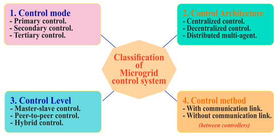
Figure 6.
Categorization of MG control techniques.
3.1. Control Mode
The MG control is divided into three levels: primary control, secondary control, and tertiary control. Despite the similarity in the division of control areas, there is an internal control mechanism between DCMGs and ACMGs due to their distinct characteristics. This is illustrated in Figure 7. The control structures for ACMGs and DCMGs are shown in Figure 7a and Figure 7b, respectively. Although the control layers are the same, the method differs due to the unique voltage, frequency, current, and power values of AC and DC power sources. The following sections provide a detailed analysis of these control methods.
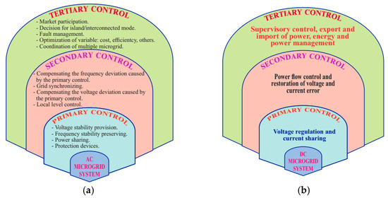
Figure 7.
The hierarchical control scheme: (a) AC microgrid and (b) DC microgrid.
3.1.1. ACMG
For the ACMG to operate safely and continuously supply electricity to loads, energy coordination and management are crucial. Compared to the DCMG, the ACMG is more reliant on characteristics such as power, voltage, and frequency. Consequently, the responsibilities of the MG controller are detailed in [20], and the hierarchical control method [20,41] is one control strategy that is used. This is demonstrated in detail in Figure 8 for the ACMG.

Figure 8.
Hierarchical control of the ACMG.
- Primary control
The internal loop converter supplies the power and frequency for this control. Droop control is a frequently utilized control strategy in this loop. In conventional droop control, the impedance of the connection is viewed as inductance, while the MG is linked to its power supply. When utilizing power electronic devices in low-voltages systems, the control strategies used determine their output impedance, while the line inductance is close to the resistance. Because there is no fluctuation in the inductance value across the line, low voltage systems do not employ this droop control method. Alternatively, the Q-V control approach is also suggested for system implementation within this framework.
In the islanded mode, when connecting to the grid, reference values will be derived from errors in the grid, including the load’s active power, reactive power, frequency, and voltage. However, the reference values will come from the grid’s parameters because these values ensure that the sources from the MG serve as a basis for adjustment. This helps the grid operate safely and stably to supply loads.
- Secondary control
To enable universal control of the MG, this second control level can be managed. The primary function of this controller, also known as the Energy Management System (ESM), is to ensure the device’s safe, reliable, and economical operation in both grid and islanded modes during process management in the MG. In this MG, the second controller for the islanded mode is the highest level of hierarchy. It has a slower control loop and limited bandwidth communication compared to the first control level. There are two primary categories of controllers based on the construction of this controller. The first kind, also referred to as distributed or decentralized controllers, relies on local measurement values. The second kind is typically considered a centralized controller and dependent on the communication link.
Centralized controller:
The MG’s dependability is maintained by using this controller. This type of controller performs better in separated MGs with a balanced supply and demand, as well as established infrastructure. Over the years, MGs have employed this controller’s approach to overcome the rated voltage and frequency values previously used for large power systems [42,43]. Similarly, other units receive this signal. Remote control on the MG for each DG and a centralized controller have been implemented [23] to manage the unbalanced voltage at PCC with the transmission grid in the untied grid mode. This handles monitoring and reactive electrical power sharing as well, preserving frequency according to the actual power [44]. The practical application of this controller is introduced in detail in reference [45].
Decentralized controller:
The primary purpose of using decentralized controllers [46] is to determine the highest power a microcontroller can produce, considering the MG’s power to support the user and raise power from the grid in exact proportion to market involvement. The second control ensures that, after each generation or load change, the frequency as well as voltage fluctuations within the MG are corrected towards zero. Power systems are subject to secondary level management regarding the allowable limits on grid frequency variations. Distribution Network Operator (DNO), MG Central Controller (MGCC), and Local Controllers (LCs) are the minimum number of levels in a hierarchical structure used to establish autonomy.
- Tertiary control
The tertiary control level is the slowest and highest level in the hierarchical control structure [41]. It offers the set point for the second control level. This level handles the frequency and voltage conversion necessary for the MG to be linked to the grid. Therefore, MG information links must be kept current at all times to monitor all system operations and ensure the system functions safely in all operational scenarios, including when the grid power is shared or absorbed during grid system oscillations. There is no need for tertiary control when the MG is in the unconnected grid mode. Table 3 outlines the processing time characteristics for each control level within an ACMG, showing the relationship between the control levels and their response time.
Table 3.
Features of the control levels at ACMG.
3.1.2. DC Microgrid
The control method for the DCMG [9] is similar to that of the ACMG, incorporating solutions such as: (i) centralized control system, (ii) decentralized control system, (iii) distributed control system, and (iv) hierarchical control system. However, DCMG does not rely on frequency, making the control process relatively simpler. Figure 7b depicts the control hierarchy for the DCMG, highlighting the roles and responsibilities of each control level.
The primary control level is responsible for voltage conversion and current sharing at DGs when connected to the microgrid. Based on the values collected from the DGs, the voltage and current conversion are calculated and balanced to supply loads.
The secondary control level addresses imbalances in power (P) and voltage (V) due to supply instability and load fluctuations. This control level adjusts power flow, restores voltage, and levels local loads by adding reserve sources from the BESS. It ensures system safety, stability, and dependability in the face of external influences.
The tertiary control level maintains a secure connection to the power grid while ensuring the DCMG’s continuous operation. It assists in preserving a secure control level that is not used in the islanded mode, similar to the ACMG.
The signal information from the DGs as well as the system must be responded to and analyzed for the purpose of providing precise instantaneous operations. Given the function of these levels, one of the essential needs for controllers is to maintain good communication channels. Table 4 outlines the processing time characteristics between tiers in the DCMG.
Table 4.
Characteristics of the DCMG’s control levels.
3.2. Control Architecture
Ensuring voltage and frequency [20] stability in MGs is a main challenge for the control process to balance local power, particularly while in the islanded mode on MGs [47]. Heat exchange, which has been removed from the definition and the overtime need, is the primary reason for the modifications made to the MG control requirements in tandem with the MG concept. The MG control system is generally expected to be able to guarantee that customers’ and the main grid’s demands are met, particularly in situations where the supply and demand are unpredictable due to intermittent power generation, possibly because of constantly shifting loads or the high degree of coordination with protective devices to handle a bidirectional current. In order to ensure customer reliability, stability in the MG operating in both the islanded and grid modes, smooth mode switching, controller of frequency, and voltage while the MG is disconnected and the addition of new DERs, it may be possible to implement capacity conversion while connected to the grid, demand-side management options with underutilized loads, or the so-called plug and play operations [48].
3.2.1. Centralized Control
The processing of data received from the system and computations while transmitting signals to every unit in the system are handled by a single primary controller in this controller. The central MG controller serves as the hub for the reception, processing, and execution of all information. This structure is described in Figure 9. The structure controller is compact and simple; however, the transmitted information is one of the very important factors for this type of processing solution, and this is also a weakness. Critically, when any information line fails, the system is almost paralyzed [49].
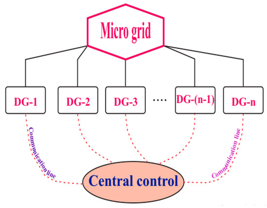
Figure 9.
Centralized control.
3.2.2. Decentralized Control
Within this control model, the controllers are situated directly at the DERs, and their job is to regulate according to both personal and local data. Some of these controllers do, however, have information linkages with one another in small groups under certain circumstances. A fast processing speed for local system changes is the main feature of this control approach; however, in the absence of global supervision, the control process lacks certainty and is more prone to disturbances due to the lack of information connections about the system [19,50]. Figure 10 shows the model.

Figure 10.
Decentralized control.
3.2.3. Distributed Multi-Control Agent
The distributed controller in MGs is shown in Figure 11. Although the aforementioned decentralized control principle forms the basis of this control method, information sharing between decentralized controllers is linked for the aim of optimization, the operation of the system, its stability, and its safety while use. However, when problems arise, the system’s calculation and processing times increase due to complete information interchange with remote controllers.

Figure 11.
Distributed multi-control agent.
The computational load on the decentralized processor will be minimal because it is implemented locally at DERs and is broken up into smaller tasks that need to be completed. This approach is based on the evaluation of the control design, which is primarily located in the central unit. Table 5 compares the elements of different control architectures.
Table 5.
Comparison of some controls’ architectural properties.
3.3. Control Level
3.3.1. Master–Slave Control
In this mode, electricity is distributed by a master-distributed generator, which sets a Vref and fref for DGs in MGs. The DG’s master is the sole component that ensures the MG operates steadily in the islanded mode. When running in the islanded mode, the MG can guarantee power to the entire load even when it is disconnected from the grid. The safe, dependable, and robust operation of the MG in the event that the grid is unavailable is the responsibility of this control mode. The primary use case for the islanded mode operation is the master–slave control system (Table 6). Figure 12 depicts the master–slave control diagram structure.
Table 6.
Comparative analysis of the control level.
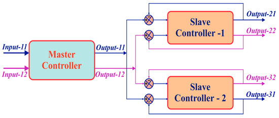
Figure 12.
Configuration of the master–slave’s controller system.
In the studies in [51,52,53], the PQ control method applied to PV panels in the MG is mentioned depending on this control system. Initially, the basic structure and operating mechanism are discussed, followed by an examination of voltage and frequency variations during the MG mode conversion process. An improved state control solution is proposed, with an energy storage P/Q controller used in the grid mode and a V/f controller used in the islanded mode. These controllers have been implemented to limit excessive fluctuations in bus voltage during the smooth switching between the grid power and RESs, based on the researched innovative state monitoring controller.
In addition, the study in [54] proposes a solution for smooth circuit switching based on master–slave control in the MG operating mode. This solution uses a BESS (lithium) power source as the main power source, with a WT, PV panel, and other energy storage systems as secondary energy sources. Based on simulation results in PSCAD under different working conditions, the MG demonstrates very good switching performance.
An imperfect aspect of this control solution is that, when controlling active and reactive power from two different power sources, the distribution has not been optimized.
3.3.2. Peer-to-Peer Control
Without considering the differences between master–slave relationships, the peer-to-peer control approach [55] is addressed in MGs in the same context. DGs need to monitor P and Q power, and fine-tune the voltage and frequency characteristic curves using an AC output busbar linked in parallel. With the help of the phase, voltage, and magnitude of the corresponding frequency’s output, the control procedure can achieve an acceptable load distribution system. Each DG’s inverters must use the same control system and parallel connection method (no cascade) to prevent output dominance issues. Additionally, inverters must operate independently to avoid local errors that can quickly lead to a loss of control [54,56]. The MG can achieve “plug and play” capabilities, functioning even if a generator is disconnected or connected (Table 6).
3.4. Control Method
3.4.1. Without Communication Link
This method involves using a controller that monitors and controls a single system or power source independently, without any connection or communication with other systems. Although this approach is very fast and economical, it is only suitable for completely isolated MG systems. The previous discussion highlights the importance of having a system that receives and processes information to ensure the comprehensive monitoring of MG operations. Since traditional MGs lack mutual information links between MGs and DGs, and information is processed in a single manner by the manufacturer, the system’s reliability may be compromised [57].
3.4.2. With Communication Link
Today, however, advancements in smart sensors and inverters with integrated management and monitoring have facilitated the receipt and interpretation of two-way information, thanks to modern power electronics technology [58]. Monitoring every parameter allows for straightforward and practical information processing. This capability has made it possible to locally distribute power and load throughout the system, ensuring stability and safety. It is crucial to act quickly in any potentially dangerous situation that could impact the grid to maintain a steady and efficient power transmission process within the MG.
Connecting data while processing MGs is therefore essential and useful in the current era due to the widespread adoption of DGs based on renewable energy sources, as well as storage energy solutions like BESSs or flywheel. A lack of connection can result in instability and cause imbalance in the system, as there will be no power sharing when a local incident occurs in the MG [59].
3.5. Modern Control Stages for MG
3.5.1. Conventional Control Methods
- V-f control
The grid supports voltage and frequency stabilization while the MG is operating in the grid-connected mode. The grid system provides immediate regulation support if any changes in the MG lead to instability. Conversely, in the islanded mode, the MG must independently ensure that V-f remains within the permissible ranges and meets the load requirements. Pure V-f control alone may not be sufficient for this purpose. To address rapid variations in the source and load, a master–slave control system is recommended as described in [28]. This system adjusts the load’s increasing or decreasing characteristics, as illustrated in Figure 13.
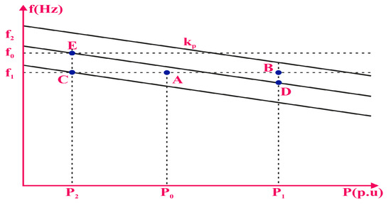
Figure 13.
V-f control.
- P-Q control
Without using the previously mentioned V-f controller, the grid mode employs the P-Q control to maintain the grid’s voltage and frequency. Currently, inverters are responsible for injecting the maximum active and reactive power into the grid under specified conditions to maximize the grid’s economic operation [60,61]. Renewable energy generators, such as wind, solar, and biogas, utilize maximum generating power to regulate the output voltage of the inverters through MPPT control. During this time, the ability to inject reactive power into the system is essentially nonexistent.
To manage power flow in the MG, a voltage variation controller adjusts the phase angle and magnitude of the output voltage from the generating sources. The active and reactive power controllers set the phase angle and system reference voltage, respectively. By modifying the amplitude and phase of the generator’s output voltage, the power flow is regulated through voltage regulation control. The reference voltage and phase angle are determined by the active and reactive power regulators, respectively. Figure 14 illustrates the P-Q control approach.
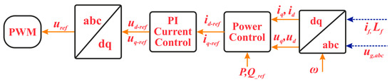
Figure 14.
Schematic of P-Q control.
- Droop control
Because most inverters employ the voltage and frequency droop feature, when reactive power increases, the voltage droops, and the load angle decreases as system output power increases by reducing the grid frequency. It will be possible to extract additional active power from the inverter by increasing the reactive power and slightly lowering the frequency and voltage. Depending on the type of power source and the various manufacturers, every inverter in a system of grid-connected inverters will also have unique properties [62]. Based on the research [63], the droop characteristics are classified as follows:
where ω* and V* represent the rated angular frequency and rated voltage, respectively, while ω and V are the reference values. l and k denote the slope of the characteristic curve. P* and Q* represent the reference active and reactive power of the system, respectively. Each DG shares the power demand in accordance with its droop characteristic function as the control method for this droop characteristic. Figure 15 displays the droop characteristics.
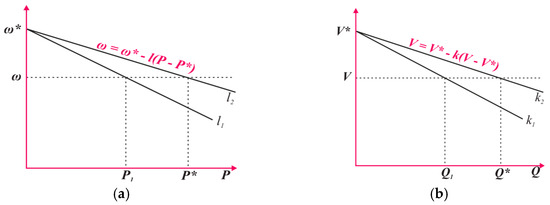
Figure 15.
Droop characteristics: (a) f-P control and (b) V-Q control.
It is clear from the aforementioned that reactive and active power both have linear relationships with the voltage and frequency. This implies that, for every variation in the frequency and voltage, you will obtain a different amount of active and reactive power. Figure 16 illustrates the reference values Vref and fref from “Droop control” calculated using the measured P and Q values, reference values P* and Q*, and rated values V* and f* as input values. These two values are then converted to the dq and dd reference frames to create two reference voltage signals, ud,ref and uq,ref, by “Voltage Formation”.
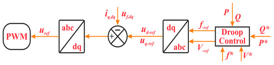
Figure 16.
Schematic of droop control.
3.5.2. Intelligent and Adaptive Control
Adaptive and intelligent control refers to control strategies where variables are processed to obtain the optimal asymptotic value while control parameters are automatically modified based on feedback values from captured signals. This feedback guarantees the system monitors all of its working conditions and takes appropriate precautions to eliminate any sources of instability and insecurity that could harm the system as a whole. Adaptive control can be implemented at each step of the operational process, utilizing sensor-based feedback from separate test stations or factory data to the system processing unit to handle a sequence of computations [64].
Managing issues in turbulent and complicated nonlinear systems offers notable benefits in the realm of intelligent control [11,65]. Numerous native neural network-based adaptive control systems are claimed to manage power plants with unknown functions, nonlinearity, multimodal behavior, randomness, and turbulence. To improve system performance, the recommended control strategies aim to increase the controller’s learning, stability, imbalance management, and adaptability. These intelligent control methods facilitate systems design, fault diagnosis, simulation, modeling, identification, efficient online monitoring, adaptation, and automatic adjustment. Artificial intelligence (AI), particularly expert system engineering [66], is developing rapidly in the control fields.
- Artificial Intelligence
AI is becoming one of the most popular terms across all study domains. This pattern of continued advancement in artificial intelligence has been validated by its remarkable success. AI can be considered a branch of computer science that builds on numerous other scientific fields to develop computer programs capable of solving issues extremely quickly and effectively. It functions similarly to the human brain. Figure 17 depicts the AI [64] classification scheme using several approaches.
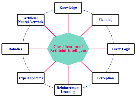
Figure 17.
Classification of AI.
There are two distinct categories for the AI control techniques [67] discussed in this study. One group develops control solutions that mimic human behavior; the other group focuses on decision-making systems capable of interpreting various inputs. These techniques are determined through experiments. Super-realistic computer programs are developed to address the intended control challenges after a series of experiments with sufficient time and desired outcomes for several systems, including smart grids or MG control methods [68].
- Artificial Neural Networks (ANNs)
Based on the physiology of the human brain, the ANN model is a type of information processing method. ANNs have led to a variety of control theories [69,70], and numerous researchers have attempted to emulate the human brain’s robust capacity for memory, reasoning, and problem-solving in computational systems. Many ANN models have been developed to date, and when applied to computer programs, they nearly perfectly mimic the way the human brain processes information. ANNs can learn the input/output relationship of any event, whether linear or nonlinear, from past occurrences. This self-learning process creates an intelligent ANN that can govern a system by retaining the chain of linked events. Figure 18 depicts a simple ANN unit. This unit consists of numerous input signals that are processed concurrently and yield the necessary output results by self-learning from previously executed events.
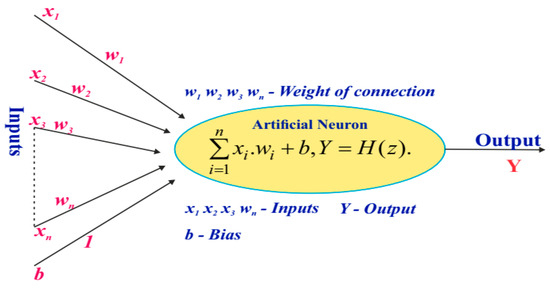
Figure 18.
Artificial neural networks.
A neural network (NN) is known for its capacities for self-learning and generalization, as well as computational properties and parallel distributed topology. ANNs can address complex and challenging issues because, based on the principle of generalization, they can generate appropriate responses to previously unseen inputs. These features make ANNs valuable in various domains, including signal processing, control, adaptive pattern recognition, and system identification. This capability aligns well with forecasting methodologies for generating power and load capacity in MG systems [67,69], particularly with the substantial involvement of renewable energy sources.
One of the notable qualities of an ANN is its capacity to store data. The weights within the neural computational network, which act as individual memories interconnected to share information about the current data, handle this information. These data are processed within the network’s memory. However, as previously indicated, data may occasionally be available or missing. In such cases, an output signal that most closely resembles the input signal is produced, reflecting the network’s ability to generalize and handle missing data. This characteristic is part of the generalization property of ANNs [71]. Figure 19 illustrates the block feedback network diagram.

Figure 19.
Structured learning structure.
In the meantime, the network structure that processes the output is known as the feedback data network. In this setup, the preceding input, the output, and intermediate layers send their information back to the preceding input units or intermediate layers. As a result, the input is propagated both forward and backward, creating a network with dynamic memory that is suitable for predictive control. Figure 20 shows the block diagram of the feedback network.
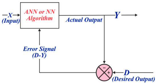
Figure 20.
Block diagram for the feedback network.
Observe how training, learning, and behavior are characterized as modifications to the natural framework of behavior. It is imperative to follow specific procedures, guidelines, observations, and training when adjusting the weights. Three distinct learning methods and rules are used for this purpose. For instance, in supervised learning [72], the ANN adjusts the number of internal connections to match the output signal by minimizing the variance between the desired and actual outputs. Consequently, this approach requires the algorithm or teacher algorithm to achieve precise results.
In the meantime, network classification rules are established through unsupervised learning using output data from input sample values. This type of self-learning algorithm does not require knowledge of the desired output value. Instead, it relies solely on input data. The network then adjusts connection weights to identify and produce patterns with related characteristics. Figure 21 illustrates the structure of the unsupervised learning scheme.
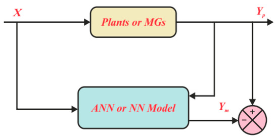
Figure 21.
Unsupervised learning structure.
The principles of reinforcement learning are akin to those of consulting. Unlike unsupervised learning algorithms [73], reinforcement Learning does not necessarily know the intended outcome in advance. Instead, it uses a criterion to evaluate the output against the input, even the target output value is known. This criterion is represented in the diagram by the sensor. Figure 22 illustrates the structure of reinforcement learning.
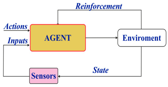
Figure 22.
Reinforced learning structure.
Additionally, various layered perceptron neural network models [74] are illustrated in Figure 23. An algorithm diagram featuring multiple layers of perceptron with feedback is also presented [75]. Having numerous intermediate processing layers can be time-consuming and requires significant computing power.
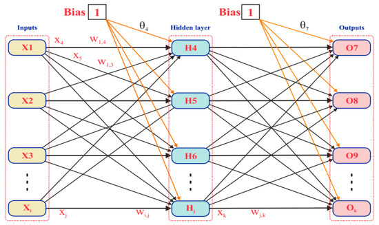
Figure 23.
Back-propagation multilayer perceptron structure.
The Genetic Algorithm (GA) is another control method integrated with ANN. GAs are research and optimization techniques based on the principles of natural biological evolution. The key features of GAs, such as probabilistic methods and the exploration of multiple potential solutions, are among their greatest strengths. They do not require knowledge of the function’s duration. Instead, information about possible solutions is communicated through the sequence of evolutionary algorithm. Figure 24 illustrates the GA diagram.
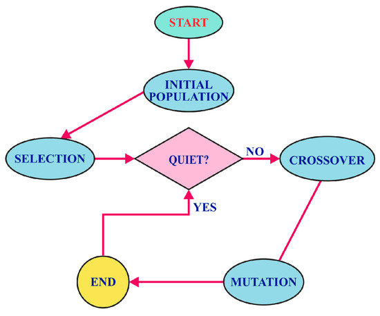
Figure 24.
Flow chart of the genetic algorithm.
The diagram illustrates that some solutions are initially generated at random by the number generator during the optimization process. One of the advantages of the GA algorithm [76] is its ability to provide accurate estimations without the requiring additional data from the outset. After creating the initial population, each solution’s quality or fitness is evaluated using the fitness function. New solutions are then generated through genetic operators, such as crossover, mutation, and selection. As the GA evolves, each new generation improves, producing solutions with increasingly exceptional characteristics that better meet the system’s needs.
- Fuzzy Logic Control (FLC)
FLC and its applications have recently gained significant attention from scientists and educators across various fields. In everyday life, many ambiguous terms are often used, especially when defining and evaluating phenomena with words or numbers, such as “too cold”, “very cold”, “somewhat cold”, “medium”, or “slightly cold”. These terms frequently lack precision and fail to provide a definitive assessment of a situation [77]. They exemplify how the human brain processes, decides, and regulates situations that are ambiguous or imprecise.
The majority of fields, including robotics, automation, intelligent control, monitoring systems, e-commerce goods, expert systems, information storage and acquisition, information processing in information-based systems, imaging, functional optimization, filtering, and curve fitting techniques, use FLC to solve issues without relying on mathematical functions. Unlike conventional techniques, FLC requires only input signals to set the desired output value. This control mechanism closely resembles human systems [78]. The FLC system block is shown in Figure 25.

Figure 25.
FLC system block diagram.
Machines can make decisions similar to those made by humans by using FLC and fuzzy set operators [78]. FLC plays an increasingly significant role in applying control to both linear and nonlinear systems. In reality, very few systems are entirely linear. FLC relies on linearity based on a rule table with element segmentation, while conventional methods require distinct linearization techniques to handle control problems. Using FLC, cost, complexity, and disturbance can be suitably reduced. The fuzzy reference system is displayed in Figure 26.
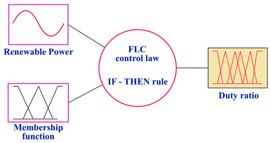
Figure 26.
Fuzzy inference system.
It is possible to achieve a better control than with traditional approaches by employing a more natural rule basis and a nonlinear control that is closer to the real system. In this situation, precise control can be accomplished, enhancing the system’s performance more effectively. Most control applications, which have several inputs, require a large number of parameters to be designed and adjusted. This makes the application difficult and time-consuming. Because FLC rules consider nonlinear features, their implementation is simplified by combining several inputs with ‘IF-THEN’ expressions. With the use of a logic processor and FLC, the output size can be expressed as a function of two or more inputs together [79]. A rule table can also represent this relationship between input and output in the following manner: fuzzify the input value first, create a rule table for the system, and then defuzzify the control system.
- Expert Systems
Because computers can multitask so well, they are incredibly useful processing tools, but they are not self-learning. However, computers’ capacity for self-learning is gradually evolving thanks to knowledge-based systems and a subfield of artificial intelligence. AI researchers aim to develop knowledge-based systems that can mimic and learn from human-like reasoning processes [80]. There is no distinction between an expert system and a knowledge-based system. The most sophisticated type of information-based system is an expert system, which serves as an open platform for discussion and is useful for posing queries, providing advice, and supporting decision-making. A back-end expert system solves a general problem rather than specific ones and tries to minimize the possibility of errors that the end user may make during inference.
The technologies utilized for either the primary or secondary expert system have equal applicability [79]. These expert systems strive to mimic human reasoning processes. They have the ability to analyze, reason, and make judgements. Expert systems find use in a wide range of domains, including weather forecasting, micro-power plant operations, financial planning, tax computation, chemical analysis, surgery, locomotive repair, computer repair, satellite repair, computer system design, and state law interpretation. These sophisticated computer programs require a great deal of specialized expertise and experience to operate effectively. The structure of the expert system is shown in Figure 27.
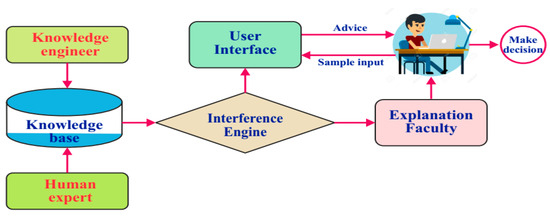
Figure 27.
Control model of the expert system.
Expert systems can resolve complex issues only when they possess deep domain knowledge and a high level of competency. They leverage artificial techniques and problem-solving procedures similar to those used by specialists in the field. Technical knowledge is realized through these systems by employing the expertise, competence, and experience of human specialists. Expert systems typically include four main elements: performance, reasonable response time, interchangeability, and an appealing user interface.
The expert System serves as a valuable resource in times of need, offering a range of suitable recommendations or explicitly indicating areas that require examination. It analyzes combinations of factors relevant to the user, allowing for detailed observations of data. However, the expert system can take a significant amount of time to process, as it must select, contrast, and compare various elements. Despite this, the extensive information gathering and retention capabilities of expert system are highly beneficial for tasks such as planning, scheduling, monitoring, process control, design, forecasting, and training in machine learning. This ultimately enhances the safety and efficiency of distribution, transmission, and grid connection in the MG.
- Adaptive control
This control strategy has been extensively studied and applied across various fields. Its primary strength lies in its ability to handle uncertainty and disruptions from unpredictable parameters. The control procedure is closely aligned with the system’s dynamic model, offering robust convergence and durable stability. However, it is important to note that operating conditions can change, which may result in suboptimal outcomes from the regulator. To address these issues and approach the ideal system condition, adaptive solutions are often employed. Figure 28 illustrates the structure of the adaptive algorithm. The PI/PID adaptive controller will be discussed in the context of MG adaptive control application, along with the responsive sliding controller and adaptive controller for reinforcement learning [11].
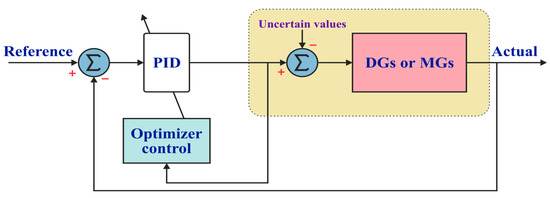
Figure 28.
Microgrid model-based adaptive control system.
Adaptive PI/PID controller:
The response of the processing system is reasonably quick when facing disturbances and changes using the conventional PID, where the signal processing depends on the gain of the input value based on error information. In conjunction with the solutions found in [81], issues related to frequency and voltage in the MG operating in the islanded mode have been addressed. Continuous operation will result in fluctuations that lead to system faults. The goal is to preserve the PID’s benefit while excellent stability and dependability under all operating circumstances via the NN. As previously indicated, NN is primarily utilized to explore ways to compensate for uncertainties caused by the unknown characteristics of distributed generators [82].
Adaptive sliding mode controller (ASMC):
A study [83] showed that, when a microgrid is operated in the islanded mode with a central control system and a controller, stability, reliability, and performance all improved. The benefit of stable adaptive sliding is that it reduces and eliminates uncertainties and disruptions. In the typical working mode of the MG, the SMC controller regulates the amount of active and reactive power at the bus bar by acting as a power quality (PQ) controller. If the MG disconnects from the grid, the SMC unit is in responsible of adjusting the voltage and frequency in the islanded mode.
One of the challenges in MGs is the use of inverters in situations where RESs are accessible. Although inverters are multifunctional devices, their involvement in MGs can contribute to system deficiencies and disruptions. According to research [84], the use of an output line virtual resistor in the islanded mode operation of an inverter in MGs, in the presence of a high-order sliding mode controller (SMC), offers a robust tool to adapt voltage and frequency to changing user load demands. To address instability issue in gas turbine generators, the adaptive slip observer (SMO) [85] is used as a real-time control mechanism for monitoring errors and adjusting any modifications to a dynamic system’s parameters. Furthermore, [86] mentions a voltage regulation technique for MG-based inverters using an adaptive SMC controller, which successfully eliminates the impact of disturbances from external and internal system parameters. Additionally, the adaptive SMC controller is used for energy storage to maintain a stable voltage in the MG system. Table 7 lists relevant published documents realted to intelligent controller applications in MGs.
Table 7.
Particular references of intelligent controller applications in MGs.
4. Discussion
The energy market is expanding rapidly due to advancements in contemporary technology. As a result, future trends will undoubtedly emphasize renewable and sustainable energy sources. Smart grids, which facilitate two-way control and monitoring between providers and customers, are set to increasingly replace conventional one-way power networks. In this context, MGs play a crucial role in the smart grid system and significantly enhance global grid coverage.
To ensure the continuous, safe, reliable, and optimal operation of the MG power grid, research and development in areas such as MG transmission, monitoring, connectivity, and integration are essential. It is important to maintain the technical role of control for an MG operating in both grid-connected and islanded modes, and the aforementioned considerations provide a solid foundation for this.
5. Trends and Future of MG
Microgrids continue to play a significant role in the modern electrical grid, helping to meet customers’ diverse energy needs. To maximize environmental protection and ensure safe and effective operation, all MG systems must integrate renewable energy sources. However, fully harnessing the potential of these clean energy sources requires effective power sharing, necessitating careful management and oversight of the controllers’ responsibilities.
High-quality results from system monitoring are essential to identify and address anomalous parameters during operation. The development of modern intelligent control techniques, combined with advancements in hardware, has elevated MGs to new heights. Their wide spread has been immensely beneficial to both individual and large-scale consumers, especially those in remote areas without access to the grid. The integration of smart controllers and streamlined communication lines will make MGs a vital component of the smart grid in the near future, enabling safe, cost-effective operation and providing increased options for electricity users.
6. Conclusions
The reviewed literature demonstrates that the use of MG control systems can enhance the safety, efficiency, and operation of the power grid. Control solutions must meet specific requirements of MGs, as they operate in two modes: the islanded mode and grid connected mode. It is evident that, while control strategies are stratified across different channels, they are closely interrelated; for example, the output parameters of one layer often serve as the input for another.
Although control solutions generally do not differ drastically, the type of MG can influence the control methods employed. Renewable energy, in particular, is essential for any type of MG. Therefore, control mechanisms designed to improve output capacity, energy management, and distribution are crucial. These mechanisms ensure power balance when the MG is connected to the grid and fully meet load requirements when operating in the islanded mode.
To create a secure, reliable, and up-to-date MG power network, these techniques rely on either conventional control methods or advanced intelligent control methods. The latter increasingly emphasize the integration and exchange of information between controllers used within the MG.
Author Contributions
M.M.: Resources, Validation, Supervision, Writing—review & editing; X.C.L.: Data curation, Formal analysis, Methodology, Writing—original draft; A.T.D.: Resources, Validation, Formal analysis; T.H.T.: Validation, Formal analysis; M.Q.D.: Conceptualization, Investigation, Methodology, Writing—original draft; G.N.T.: Writing—review & editing. All authors have read and agreed to the published version of the manuscript.
Funding
This research is funded by Funds for Science and Technology Development of the University of Danang under project number B2023-DN01-03.
Conflicts of Interest
The authors declare no conflicts of interest.
Abbreviations
The following abbreviations are used in this manuscript:
| Abbreviations | Signification |
| AC | Alternate current |
| ACMG | Alternate current microgrid |
| AI | Artificial intelligence |
| ANN | Artificial neural network |
| ASMC | Adaptive sliding mode controller |
| BESS | Battery energy storage system |
| DC | Direct current |
| DCMG | Direct current microgrid |
| DER | Distributed energy resources |
| DG | Distributed generator |
| DG | Distributed generator |
| FLC | Fuzzy logic control |
| GA | Genetic algorithm |
| MG | Microgrid |
| MGs | Microgrids |
| MPPT | Maximum power point tracking |
| NN | Neural network |
| P | Active power |
| PCC | Point common coupling |
| PI | Proportional–integral |
| PID | Proportional–integral–derivative |
| PV | Photovoltaic |
| Q | Reactive power |
| SMC | Sliding mode controller |
References
- Wang, Y.; Wang, Z.; Sheng, H. Optimizing wind turbine integration in microgrids through enhanced multi-control of energy storage and micro-resources for enhanced stability. J. Clean. Prod. 2023, 444, 140965. [Google Scholar] [CrossRef]
- Aziz, T.; Salman, S.I.M.; Islam, M.S.; Razzaq, A.; Chowdhury, R.A.; Mitun, M.I.H. Integration of Wind Energy System in Microgrid Considering Static and Dynamic Issues. In Proceedings of the 2nd International Conference on Electrical Engineering and Information & Communication Technology (ICEEICT), Savar, Bangladesh, 21–23 May 2015; pp. 1–5. [Google Scholar]
- Canziani, F.; Vargas, R.; Gastelo-Roque, J.A. Hybrid Photovoltaic-Wind Microgrid with Battery Storage for Rural Electrification: A Case Study in Perú. Orig. Res. 2021, 8, 528571. [Google Scholar] [CrossRef]
- Nasab, N.M.; Kilby, J.; Bakhtiary, L. Case Study of a Hybrid Wind and Tidal Turbines System with a MG for Power Supply to a Remote Off-Grid Community in New Zealand. Energies 2021, 14, 3636. [Google Scholar] [CrossRef]
- Alzahrani, A.; Kumar, R.S.; Devarajan, G.; Indragandhi, V. A Review on Hydrogen-Based Hybrid Microgrid System: Topologies for Hydrogen Energy Storage, Integration, and Energy Management with Solar and Wind Energy. Energies 2022, 15, 7979. [Google Scholar] [CrossRef]
- Kikusato, H.; Ustun, T.S.; Suzuki, M.; Sugahara, S.; Hashimoto, J.; Otani, K.; Ikeda, N.; Komuro, I.; Yokoi, H.; Takahashi, K. Flywheel energy storage system based microgrid controller design and PHIL testing. Energy Rep. 2022, 8, 470–475. [Google Scholar] [CrossRef]
- Bunker, K.J.; Weaver, W. Optimal geometric control of Dc microgrids. In Proceedings of the 2014 IEEE 15th Workshop on Control and Modeling for Power Electronics, Santander, Spain, 22–25 June 2014; pp. 1–7. [Google Scholar]
- Kumar, J.; Agarwal, A.; Agarwal, V. A review on overall control of DC microgrids. J. Energy Storage 2019, 21, 113–138. [Google Scholar] [CrossRef]
- Abhishek, A.; Ranjan, A.; Devassy, S.; Verma, B.K.; Kumar, S.; Ram; Dhakar, A.K. Review of hierarchical control strategies for DC microgrid. IET Renew. Power Gener. 2020, 14, 1631–1640. [Google Scholar] [CrossRef]
- Kaviri, S.M.; Pahlevani, M.; Jain, P.; Bakhshai, A. A Review of AC Microgrid Control Methods. In Proceedings of the 2017 IEEE 8th International Symposium on Power Electronics for Distributed Generation Systems (PEDG), Florianopolis, Brazil, 17–20 April 2017; pp. 1–8. [Google Scholar]
- Mahmoud, M.S.; Alyazidi, N.M.; Abouheaf, M.I. Adaptive intelligent techniques for microgrid control systems: A survey. Int. J. Electr. Power Energy Syst. 2017, 90, 292–305. [Google Scholar] [CrossRef]
- Zhou, X.; Guo, T.; Ma, Y. An Overview on Microgrid Technology. In Proceedings of the International Conference on Mechatronics and Automation, Beijing, China, 2–5 August 2015; pp. 1–6. [Google Scholar]
- Bashir, S.B.; Ismail, A.A.A.; Elnady, A.; Farag, M.M.; Hamid, A.-K.; Bansal, R.C.; Abo-Khalil, A.G. Modular Multilevel Converter-Based Microgrid: A Critical Review. IEEE Access 2023, 11, 65569–65589. [Google Scholar] [CrossRef]
- Erenoğlu, A.K.; Sancar, S.; Erdinç, O.; Bağriyanik, M. A topological overview of microgrids: From maturity to the future. Turk. J. Electr. Eng. Comput. Sci. 2021, 29, 1308–1353. [Google Scholar] [CrossRef]
- Ahmed, I.; Rehan, M.; Basit, A.; Ahmad, H.; Ahmed, W.; Ullah, N.; Piecha, M.; Blazek, V.; Prokop, L. Review on microgrids design and monitoring approaches for sustainable green energy networks. Sci. Rep. 2023, 13, 21663. [Google Scholar] [CrossRef] [PubMed]
- Pires, V.F.; APires, A. and Cordeiro A. DC Microgrids: Benefits, Architectures, Perspectives and Challenges. Energies 2023, 16, 1727. [Google Scholar] [CrossRef]
- Villalón, A.; Rivera, M.; Salgueiro, Y.; Muñoz, J.; Dragi, T.; Blaabjerg, F. Predictive Control for Microgrid Applications A Review Study. Energies 2020, 13, 2454. [Google Scholar] [CrossRef]
- Nishikawa, K.; Shimoda, E.; Shimoda, E.; Nitta, T.; Nitta, T.; Masada, E. Design Methods and Integrated Control Design Methods and Integrated Control; IEEE: Piscataway, NJ, USA, 2008; pp. 1–7. [Google Scholar]
- Ghazanfar, S. A brief review on microgrids: Operation, applications, modeling, and control. Int. Trans. Electr. Energy Syst. 2021, 31, e12885. [Google Scholar]
- Rajesh, K.S.; Dash, S.S.; Rajagopal, R.; Sridhar, R. A review on control of ac microgrid. Renew. Sustain. Energy Rev. 2017, 71, 814–819. [Google Scholar] [CrossRef]
- Zhou, Y.; Ngai, C.; Ho, M. A Review on Microgrid Architectures and Control Methods. In Proceedings of the 2016 IEEE 8th International Power Electronics and Motion Control Conference (IPEMC-ECCE Asia), Hefei, China, 22–26 May 2016; pp. 1–8. [Google Scholar]
- Pabbuleti, B.; Somlal, J. A review on hybrid ac/dc microgrids: Optimal sizing, stability control and energy management approaches. J. Crit. Rev. 2020, 7, 376–381. [Google Scholar]
- Barik, A.K.; Jaiswal, S.; Das, D.C. Recent trends and development in hybrid microgrid: A review on energy resource planning and control. Int. J. Sustain. Energy 2022, 41, 308–322. [Google Scholar] [CrossRef]
- Azeem, O.; Ali, M.; Abbas, G.; Uzair, M.; Qahmash, A.; Algarni, A.; Hussain, M.R. A Comprehensive Review on Integration Challenges, Optimization Techniques and Control Strategies of Hybrid AC/DC Microgrid. Appl. Sci. 2021, 11, 6242. [Google Scholar] [CrossRef]
- Dawoud, S.M.; Lin, X.; Okba, M.I. Hybrid renewable microgrid optimization techniques: A review. Renew. Sustain. Energy Rev. 2018, 82, 2039–2052. [Google Scholar] [CrossRef]
- Chau, L.X.; Thanh, T.V.; Quan, D.M.; Hung, L.K.; Hieu, T.T. Using Statcom Devices To Control And Maintain Voltage Stability In Wind Turbine Generators. In Proceedings of the 2023 Asia Meeting on Environment and Electrical Engineering (EEE-AM), Hanoi, Vietnam, 13–15 November 2023; pp. 1–5. [Google Scholar]
- Phan, T.M.; Nguyen, T.T.; Duong, M.Q.; Nguyen, T.T. Optimal design and operation of battery energy storage systems in renewable power plants to reach maximum total electric sale revenues. Neural Comput. Appl. 2024, 36, 1–22. [Google Scholar] [CrossRef]
- Sen, S.; Kumar, V. Microgrid control: A comprehensive survey. Annu. Rev. Control. 2018, 45, 118–151. [Google Scholar] [CrossRef]
- Gheorghiu, C.; Scripcariu, M.; Tanasiev, G.N.; Gheorghe, S.; Duong, M.Q. A Novel Methodology for Developing an Advanced Energy-Management System. Energies 2024, 17, 1605. [Google Scholar] [CrossRef]
- Le, C.; Chien, D.N.; Tuong, N.T.C.; Hieu, T.T.; Duong, M.Q. Improving Efficient Smart Management of Power Transmission Network Using BIM Technology. Meas. Control Autom. 2024, 5, 54–59. [Google Scholar]
- Chen, X.; Wang, Y.H.; Wang, Y.C. A novel seamless transferring control method for microgrid based on master-slave configuration. In Proceedings of the 2013 IEEE ECCE Asia Downunder, Melbourne, VIC, Australia, 3–6 June 2013; pp. 351–357. [Google Scholar]
- El-Shahat, A.; Sumaiya, S. DC-Microgrid System Design, Control, and Analysis. Electronics 2019, 8, 124. [Google Scholar] [CrossRef]
- Bharath, K.R.; Mithun, M.K.; Kanakasabapathy, P. A Review on DC Microgrid Control Techniques, Applications and Trends. Int. J. Renew. Energy Res. 2019, 9, 1328–1338. [Google Scholar]
- Lonkar, M.; Ponnaluri, S. An Overview of DC Microgrid Operation and Control. In Proceedings of the 6th International Renewable Energy Congress (IREC), Sousse, Tunisia, 24–26 March 2015; pp. 1–6. [Google Scholar]
- Wu, Y.; Wu, Y.; Guerrero, J.M.; Vasquez, J.C.; Li, J. AC Microgrid Small-Signal Modeling. IEEE Electrif. Mag. 2019, 7, 80–88. [Google Scholar] [CrossRef]
- Khayat, Y.; Shafiee, Q.; Heydari, R.; Naderi, M.; Dragicevic, T. On the Secondary Control Architectures of AC Microgrids: An Overview. IEEE Trans. Power Electron. 2020, 35, 6482–6500. [Google Scholar] [CrossRef]
- Hou, X.; Sun, Y.; Lu, J.; Zhang, X.; Koh, L.H.; Su, M.; Guerrero, J.M. Distributed Hierarchical Control of AC Microgrid Operating in Grid-Connected, Islanded and Their Transition Modes. IEEE Access 2018, 6, 77388–77401. [Google Scholar] [CrossRef]
- Navarro-Rodríguez, Á.; García, P.; García, J. Adaptive Active Power Sharing Techniques for DC and AC Voltage Control in a Hybrid DC/AC Microgrid. IEEE Trans. Ind. Appl. 2019, 55, 1106–1116. [Google Scholar] [CrossRef]
- Nejabatkhah, F.; Li, Y.W.; Tian, H. Power Quality Control of Smart Hybrid AC/DC Microgrids: An Overview. IEEE Access 2019, 2, 52295–52318. [Google Scholar] [CrossRef]
- Ansari, S.; Chandel, A.; Tariq, M. A Comprehensive Review on Power Converters Control and Control Strategies of AC/DC Microgrid. IEEE Access 2020, 9, 17998–18015. [Google Scholar] [CrossRef]
- Van Tan, N.; Lam, L.H.; Quan, D.M.; Hieu, N.H.; Hung, L.K. A Thorough Overview of Hierarchical Structure of Microgrid Systems. In Proceedings of the International Conference on Green Technology and Sustainable Development, Ho Chi Minh City, Vietnam, 23–24 November 2018; pp. 1–6. [Google Scholar]
- Olivares Daniel, E.; Mehrizi-Sani, A.; Etemadi, A.H.; Cañizares, C.A.; Iravani, R.; Kazerani, M.; Hajimiragha, A.H.; Bellmunt, O.G.; Saeedifard, M.; Palma-Behnke, R.; et al. Trends in microgrid control. IEEE Trans. Smart Grid 2014, 5, 1905–1919. [Google Scholar] [CrossRef]
- Vandoorn Tine, L.; Vasquez, J.C.; De Kooning, J.; Guerrero, J.M.; Vandevelde, L. Microgrids: Hierarchical control and an overview of the control and reserve management strategies. IEEE Ind. Electron. Mag. 2013, 7, 42–55. [Google Scholar] [CrossRef]
- Venkataramanan, G.; Illindala, M. Small signal dynamics of inverter interfaced distributed generation in a chain-microgrid. In Proceedings of the IEEE Power Engineering Society General Meeting, Tampa, FL, USA, 24–28 June 2007; pp. 1–6. [Google Scholar]
- Tabatabaei, N.M.; Kabalci, E.; Bizon, N. Microgrid Architectures, Control and Protection Methods; Springer: Baku, Azerbaijan, 2019. [Google Scholar]
- Alfergani, A.; Alfaitori, K.A.; Khalil, A.; Buaossa, N. Control Strategies in AC Microgrid: A Brief Review. In Proceedings of the 9th International Renewable Energy Congress (IREC 2018), Hammamet, Tunisia, 20–22 March 2018. [Google Scholar]
- Valedsaravi, S.; El Aroudi, A.; Barrado-Rodrigo, J.A.; Issa, W.; Martínez-Salamero, L. Control Design and Parameter Tuning for Islanded Microgrids by Combining Different Optimization Algorithms. Energies 2022, 15, 3756. [Google Scholar] [CrossRef]
- Meng, L.; Shafiee, Q.; Trecate, G.F.; Karimi, H.; Fulwani, D.; Lu, X.; Guerrero, J.M. Review on Control of DC Microgrids. IEEE J. Emerg. Sel. Top. Power Electron. 2017, 5, 928–948. [Google Scholar] [CrossRef]
- Cintuglu, M.H.; Youssef, T.; Mohammed, O.A. Development and Application of a Real-Time Testbed for Multiagent System Interoperability: A Case Study on Hierarchical Microgrid Control. IEEE Power Energy Soc. Gen. Meet. 2017, 9, 1759–1768. [Google Scholar]
- Ahmethodzica, L.; Music, M. Comprehensive review of trends in microgrid control. Renew. Energy Focus 2021, 38, 84–96. [Google Scholar] [CrossRef]
- Li, X.; Li, J.; Zhu, J.; Wang, Y.; Li, H. Study on control strategy of micro-grid combined with load switching. Heilongjiang Power 2015, 37, 353–356. [Google Scholar]
- Ping, J.; Pupu, C.; Yaodong, T. Multi-loop master-slave control strategy for smooth switching of microgrids. Acta Sci. Circumstantiae 2016, 14, 128–136. [Google Scholar]
- Li, Y. Study on Smooth Switching Control Strategy of Micro-Grid Based on Master-Slave Structure. Master’s Thesis, Xinjiang University, Ürümqi, China, 2016. [Google Scholar]
- Zhang, Y.; Feng, X.; Yu, H.; Ling, P.; Shi, S.; Yang, P. Study on Switching Strategy of Wind Power Storage Micro-Grid Mode. Electr. Meas. Instrum. 2016, 53, 38–50. [Google Scholar]
- Guo, L.; Wang, C.; Guo, L.; Cao, J. Dynamical characteristic of microgrid with peer to peer control. In Proceedings of the IEEE/CICED, Guangzhou, China, 10–13 December 2008; pp. 1–7. [Google Scholar]
- Zhao, X.; Wu, J.; Jenkins, N. An Overview Of Microgrid Control. Intell. Autom. Soft Comput. 2010, 16, 199–212. [Google Scholar]
- Juan, M.; Rey, P.M.; Velasco, M.; Miret, J. Secondary Switched Control with no Communications for Islanded Microgrids. IEEE Trans. Ind. Electron. 2017, 64, 8534–8545. [Google Scholar]
- Rat, C.L.; Ichim-Burlacu, C.; Panoiu, M. The impact of communication on microgrid control. In Proceedings of the International Conference on Applied Sciences (ICAS 2021), Banja Luka, Bosnia and Herzegovina, 24–28 May 2022; pp. 1–7. [Google Scholar]
- Bindhu, S.; Prabha, D.M.M.S.R. A Survey on Control and Communication of Smart Micro Grid. Indian J. Sci. Technol. 2015, 1–6, 8. [Google Scholar] [CrossRef]
- Zhou, X.; Cui, L.; Ma, Y. Research on control of micro grid. In Proceedings of the IEEE Third International Conference on Measuring Technology and Mechatronics Automation, Shanghai, China, 6–7 January 2011; pp. 1129–1132. [Google Scholar]
- Peng, F.Z.; Li, Y.W.; Tolbert, L.M. Control and protection of power electronics interfaced distributed generation systems in a customer driven microgrid. In Proceedings of the IEEE PES General Meeting, Calgary, AB, Canada, 26–30 July 2009; pp. 1–8. [Google Scholar]
- Chen, H.; Zhang, X.; Liu, S.; Yang, S. Research on control strategies for distributed inverters in low-voltage microgrids. In Proceedings of the IEEE International Symposium on Power Electronics for Distributed Generation System, Hefei, China, 16–18 June 2010; pp. 748–752. [Google Scholar]
- Guerrero, J.M.; Vasquez, J.C.; Matas, J.; Vicuna, L.G.; Castilla, M. Hierachical control of droop- controlled AC and DC microgrid—A general approach toward standardization. IEEE Trans. Ind. Electron. 2011, 58, 158–172. [Google Scholar] [CrossRef]
- Kosko, B. Fuzzy Engineering; Prentince Hall: Hoboken, NJ, USA, 1997; pp. 25–59. [Google Scholar]
- Logenthiran, T.; Naayagi, R.T.; Woo, W.L.; Phan, V.-T.; Abidi, K. Intelligent Control System for Microgrids Using Multi-Agent System. IEEE J. Emerg. Sel. Top. Power Electron. 2015, 3, 1036–1045. [Google Scholar] [CrossRef]
- Mohammadi, E.; Alizadeh, M.; Asgarimogh, M. A Review on Application of Artificial Intelligence Techniques in Microgrids. IEEE J. Emerg. Sel. Top. Ind. Electron. 2022, 3, 878–890. [Google Scholar] [CrossRef]
- Gill, N. Artificial Neural Networks, Neural Networks Applications and Algorithms. 2018. Available online: https://www.xenonstack.com/ (accessed on 20 February 2024).
- Lv, L.; Wu, Z.; Zhang, L.; Gupta, B.B.; Tian, Z. An Edge-AI Based Forecasting Approach for Improving Smart Microgrid Efficiency. IEEE Trans. Ind. Inform. 2022, 18, 7946–7954. [Google Scholar] [CrossRef]
- Abdolrasol, M.G.M.; Mohamed, R.; Hannan, M.A.; Al-Shetwi, A.Q.; Mansor, M.; Blaabjerg, F. Artificial Neural Network Based Particle Swarm Optimization for Microgrid Optimal Energy Scheduling. IEEE Trans. Power Electron. 2021, 36, 12151–12157. [Google Scholar] [CrossRef]
- Abbass Muhammad, J.; Lis, R.; Mushtaq, Z. Artificial Neural Network (ANN)-Based Voltage Stability Prediction of Test Microgrid Grid. IEEE Access 2023, 11, 58994–59001. [Google Scholar] [CrossRef]
- Mathworks. Design Neural Network Predictive Controller in Simulink. 25 August 2018. Available online: https://www.mathworks.com/help/deeplearning/ug/design.htm (accessed on 20 February 2024).
- Salehi, N.; Martínez-García, H.; Velasco-Quesada, G. Networked Microgrid Energy Management Based on Supervised and Unsupervised Learning Clustering. Energies 2021, 15, 4915. [Google Scholar] [CrossRef]
- Tomin, N.; Zhukov, A.; Domyshev, A. Deep Reinforcement Learning for Energy Microgrids Management Considering Flexible Energy Sources. EPJ Web Conf. 2019, 217, 01016. [Google Scholar] [CrossRef]
- Abdali, A.; Mazlumi, K.; Noroozian, R. A Precise Fault Location Scheme for Low-Voltage Dc Microgrids Systems Using Multi-Layer Perceptron Neural Network. Res. Artic. 2018, 36, 821–834. [Google Scholar]
- Moallem, P.; Razmjooy, N. A multi layer perceptron neural network trained by invasive weed optimization for potato color image segmentation. Trends Appl. Sci. Res. 2012, 7, 445–455. [Google Scholar] [CrossRef]
- Ravale, U.; Marathe, N.; Padiya, P. Feature selection based on genetic algorithm and support vector machine for intrusion detection system. Procedia Comput. Sci 2015, 45, 428–435. [Google Scholar] [CrossRef]
- Kakigano, H.; Miura, Y.; Ise, T. Distribution Voltage Control for DC Microgrids Using Fuzzy Control and Gain-Scheduling Technique. IEEE Trans. Power Electron. 2013, 28, 2246–2258. [Google Scholar] [CrossRef]
- Shan, Y.; Hu, J.; Chan Ka, W.; Islam, S. A Unified Model Predictive Voltage and Current Control for Microgrids with Distributed Fuzzy Cooperative Secondary Control. IEEE Trans. Ind. Inform. 2021, 17, 8024–8034. [Google Scholar] [CrossRef]
- Žarković, M.; Dobrić, G. Fuzzy expert system for management of smart hybrid energy microgrid. J. Renew. Sustain. Energy 2019, 11, 1–15. [Google Scholar] [CrossRef]
- Moreira Alexandre, C.; Paredes Helmo, K.M.; de Souza, W.A.; Marafão, F.P. Intelligent Expert System for Power Quality Improvement under Distorted and Unbalanced Conditions in Three-Phase AC Microgrids. IEEE Trans. Smart Grid 2017, 9, 6951–6960. [Google Scholar] [CrossRef]
- Mahmoud, M.S.; Azher, S.H. Adaptive PI secondary control for smart autonomous microgrid systems. Int. J. Adapt. Control Signal Process. 2015, 29, 1442–1458. [Google Scholar] [CrossRef]
- Barbosa, R.A.; de Almeida Souza, D.; da Nóbrega Tahim, A.P. Adaptive Control of DC Microgrid Using PI Controller and Fuzzy Inference. In Proceedings of the IEEE PES Innovative Smart Grid Technologies Conference—Latin America (ISGT Latin America), Gramado, Brazil, 15–18 September 2019; pp. 1–6. [Google Scholar]
- Su, X.; Han, M.; Guerrero, J.M.; Sun, H. Microgrid stability controller based on adaptive robust total SMC. Energies 2015, 8, 1784–1801. [Google Scholar] [CrossRef]
- Liu, Y.; Zhang, Q.; Wang, C.; Wang, N. A control strategy for microgrid inverters based on adaptive three-order sliding mode and optimized droop controls. Electr. Power Syst. Res. 2014, 38, 192–201. [Google Scholar] [CrossRef]
- Rahme, S.; Meskin, N. Adaptive sliding mode observer for sensor fault diagnosis of an industrial gas turbine. Control Eng. Pract. 2015, 38, 57–74. [Google Scholar] [CrossRef]
- Trivedi, R.; Khadem, S. Implementation of artificial intelligence techniques in microgrid control environment: Current progress and future scopes. Energy AI 2022, 8, 100147. [Google Scholar] [CrossRef]
- Zhou, S.; Qin, L.; Ruan, J.; Wang, J.; Liu, H.; Tang, X.; Wang, X.; Liu, K. An AI-Based Power Reserve Control Strategy for Photovoltaic Power Generation Systems Participating in Frequency Regulation of Microgrids. Electronics 2023, 12, 2075. [Google Scholar] [CrossRef]
- Dong, W.; Li, S.; Fu, X. Artificial Neural Network Control of A Standalone DC Microgrid. In Proceedings of the 2018 Clemson University Power Systems Conference (PSC), Charleston, SC, USA, 4–7 September 2018; pp. 1–5. [Google Scholar]
- Boujoudar, Y.; Azeroual, M.; Elmoussaoui, H.; Lamhamdi, T. Intelligent control of battery energy storage for microgrid energy management using ANN. Int. J. Electr. Comput. Eng. 2021, 11, 2760–2767. [Google Scholar] [CrossRef]
- Rehimi, S.; Mirzaei, R.; Bevrani, H. ANN-Based Frequency and Tie-Line Power Control in Interconnected Microgrids. In Proceedings of the 2019 6th International Conference on Control, Instrumentation and Automation (ICCIA), Sanandaj, Iran, 30–31 October 2020; pp. 1–5. [Google Scholar]
- Chettibi, N.; Mellit, A.; Sulligoi, G.; Pavan, A.M. Adaptive Neural Network-Based Control of a Hybrid AC/DC Microgrid. IEEE Trans. Smart Grid 2018, 9, 1667–1679. [Google Scholar] [CrossRef]
- Lopez-Garcia, T.B.; Coronado-Mendoza, A.; Domínguez-Navarro, J.A. Artificial neural networks in microgrids: A review. Eng. Appl. Artif. Intell. 2020, 95, 103894. [Google Scholar] [CrossRef]
- Arwa, E.O.; Folly, K.A. Reinforcement Learning Techniques for Optimal Power Control in Grid-Connected Microgrids: A Comprehensive Review. IEEE Access 2020, 8, 208992–209007. [Google Scholar] [CrossRef]
- Angalaeswari, S.; Swathika, O.V.G.; Ananthakrishnan, V.; Daya, J.L.F.; Jamuna, K. Efficient Power Management of Grid operated MicroGrid Using Fuzzy Logic Controller (FLC). In Proceedings of the 1st International Conference on Power Engineering, Computing and CONtrol, PECCON-2017, Chennai, India, 2–4 March 2017; pp. 268–274. [Google Scholar]
- Maged, N.A.; Hasanien, H.M.; Ebrahim, E.A.; Tostado-Véliz, M.; Turky, R.A.; Jurado, F. Optimal Real-time implementation of fuzzy logic control strategy for performance enhancement of autonomous microgrids. Int. J. Electr. Power Energy Syst. 2023, 151, 109140. [Google Scholar] [CrossRef]
- Al Badwawi, R.; Issa, W.R.; Mallick, T.K. Supervisory Control for Power Management of an Islanded AC Microgrid Using a Frequency Signalling-Based Fuzzy Logic Controller. IEEE Trans. Sustain. Energy 2019, 10, 94–104. [Google Scholar] [CrossRef]
- Vu, T.V.; Perkins, D.; Diaz, F.; Gonsoulin, D.; Edrington, C.S.; El-Mezyani, T. Robust adaptive droop control for DC microgrids. Electr. Power Syst. Res. 2017, 146, 95–106. [Google Scholar] [CrossRef]
- Teimourzadeh, S.; Aminifar, F.; Davarpanah, M.; Shahidehpour, M. Adaptive Control of Microgrid Security. IEEE Trans. Smart Grid 2018, 9, 3909–3910. [Google Scholar] [CrossRef]
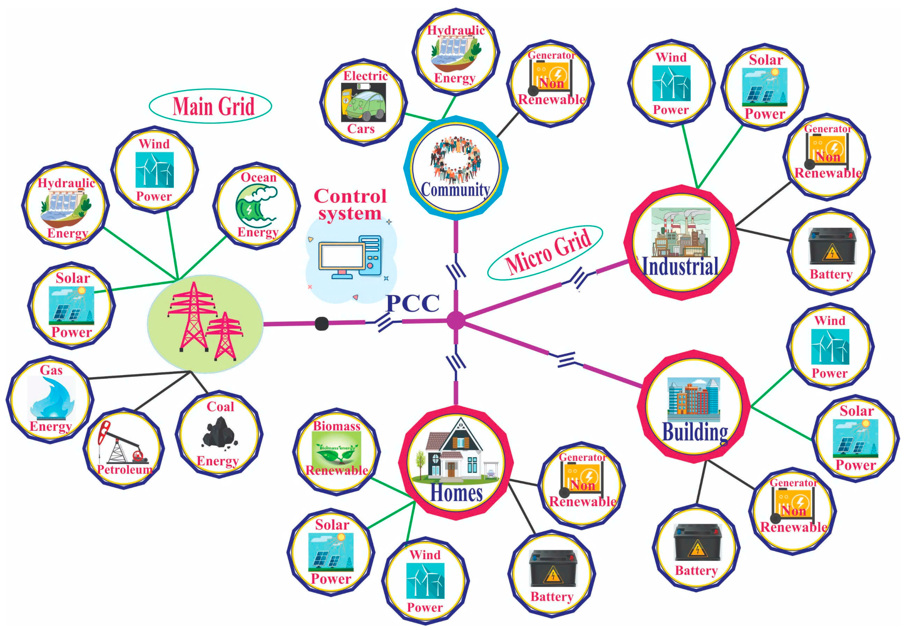
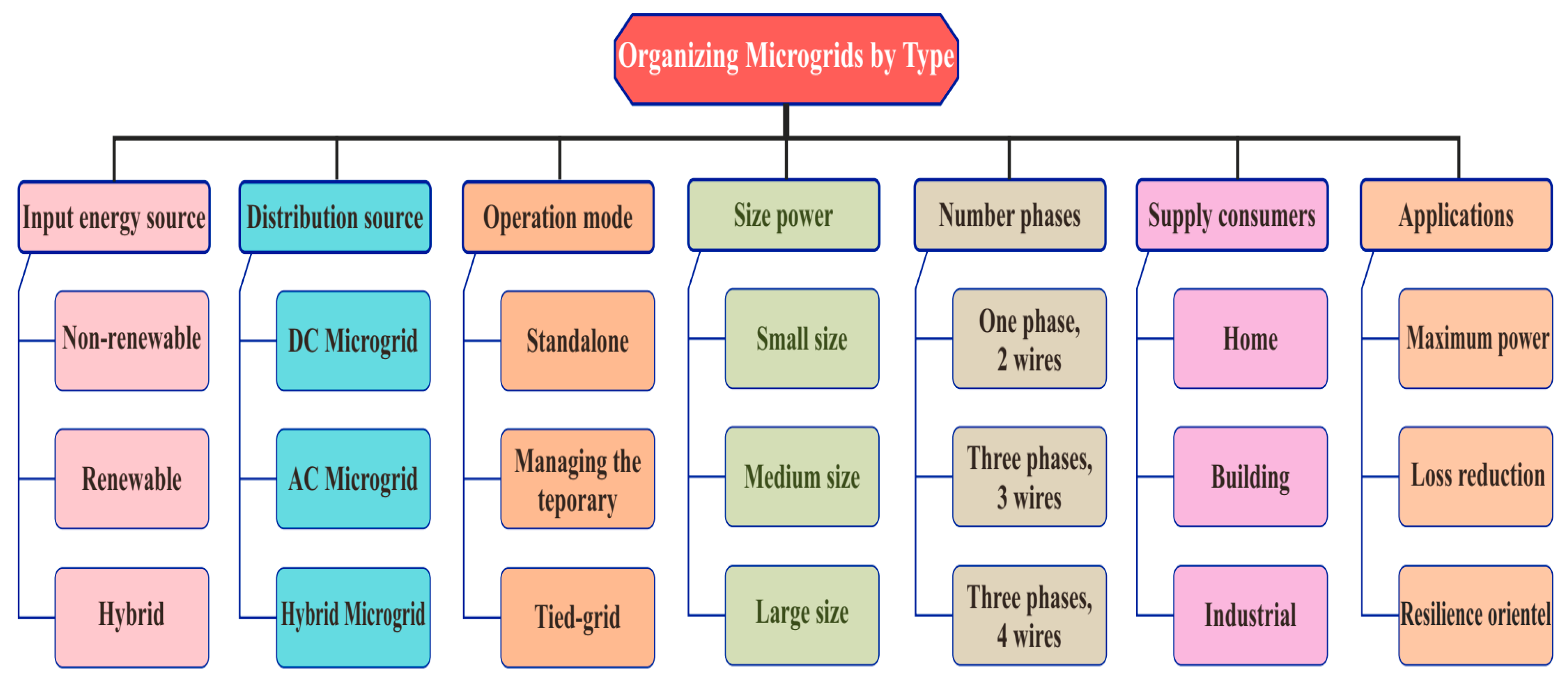
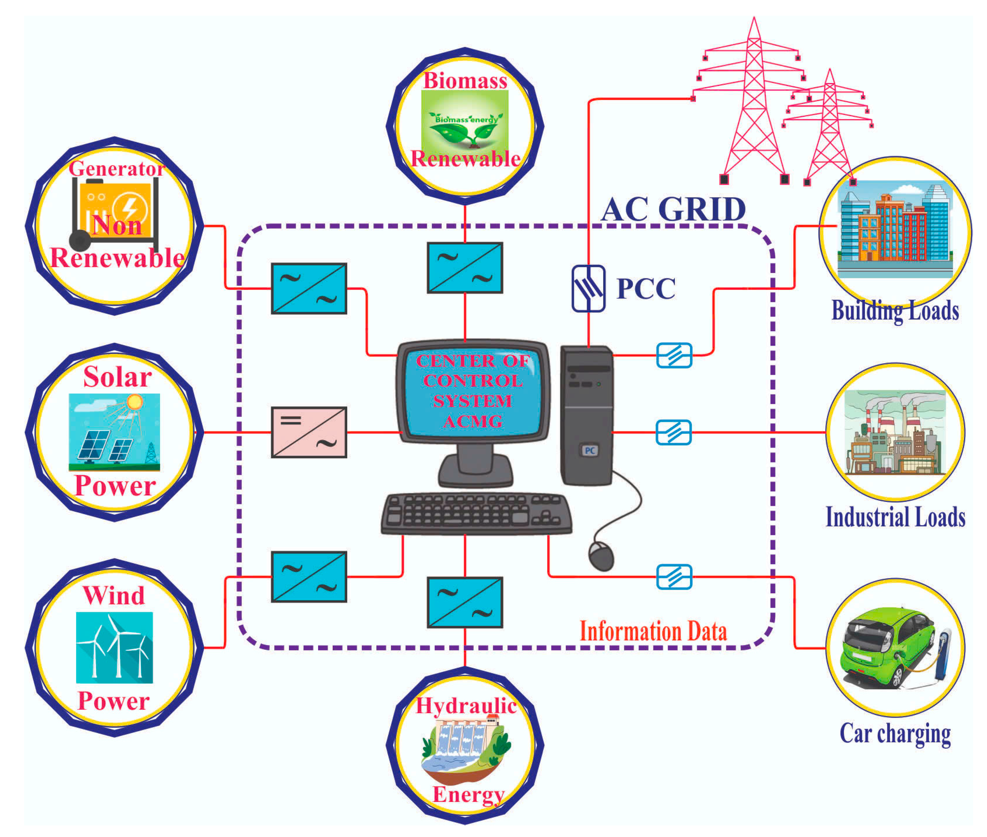
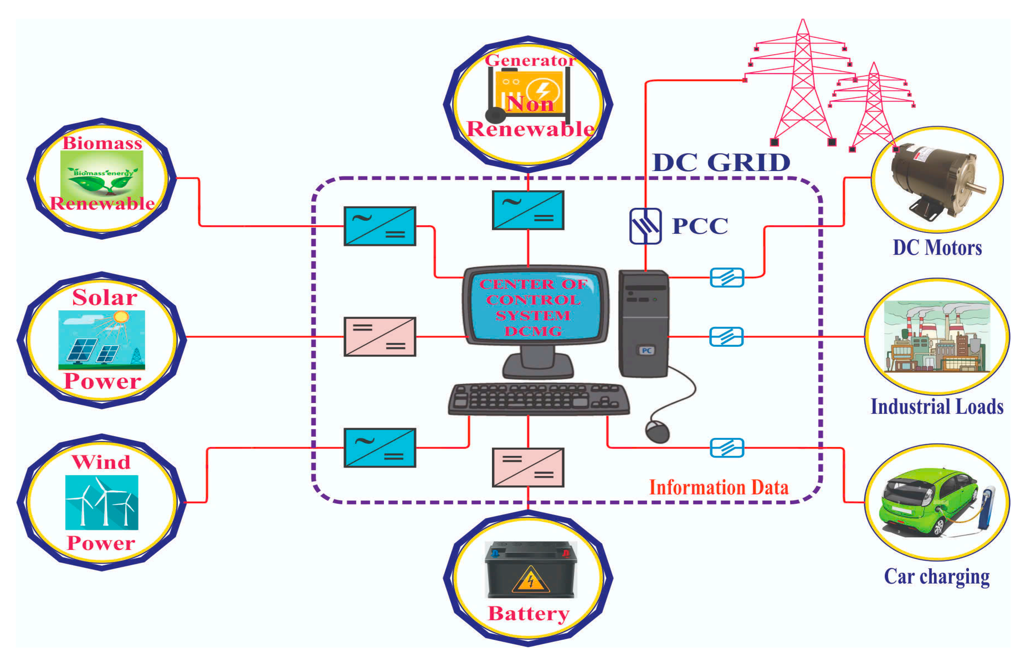
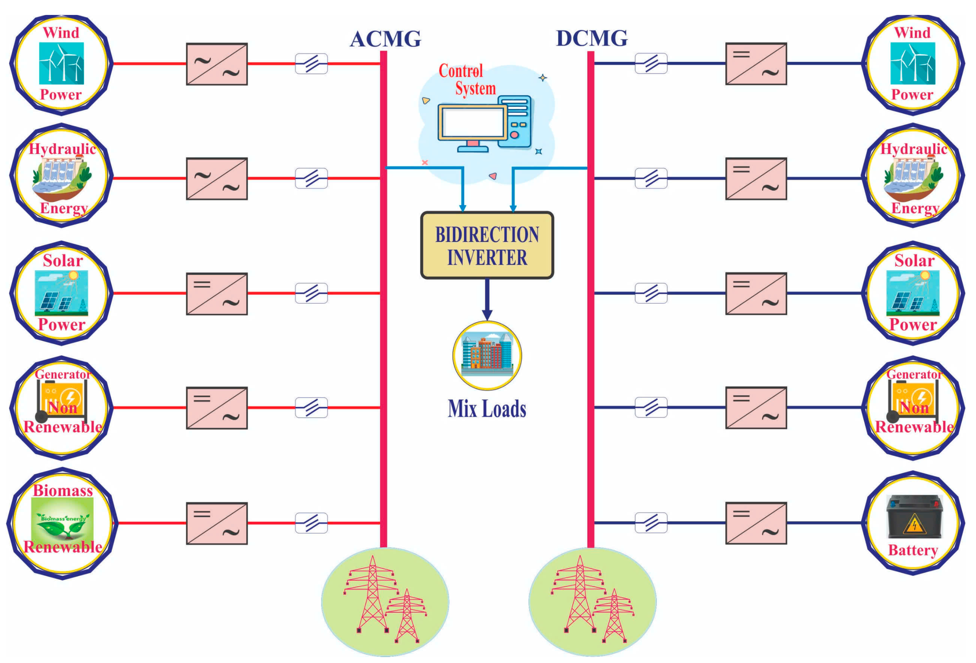
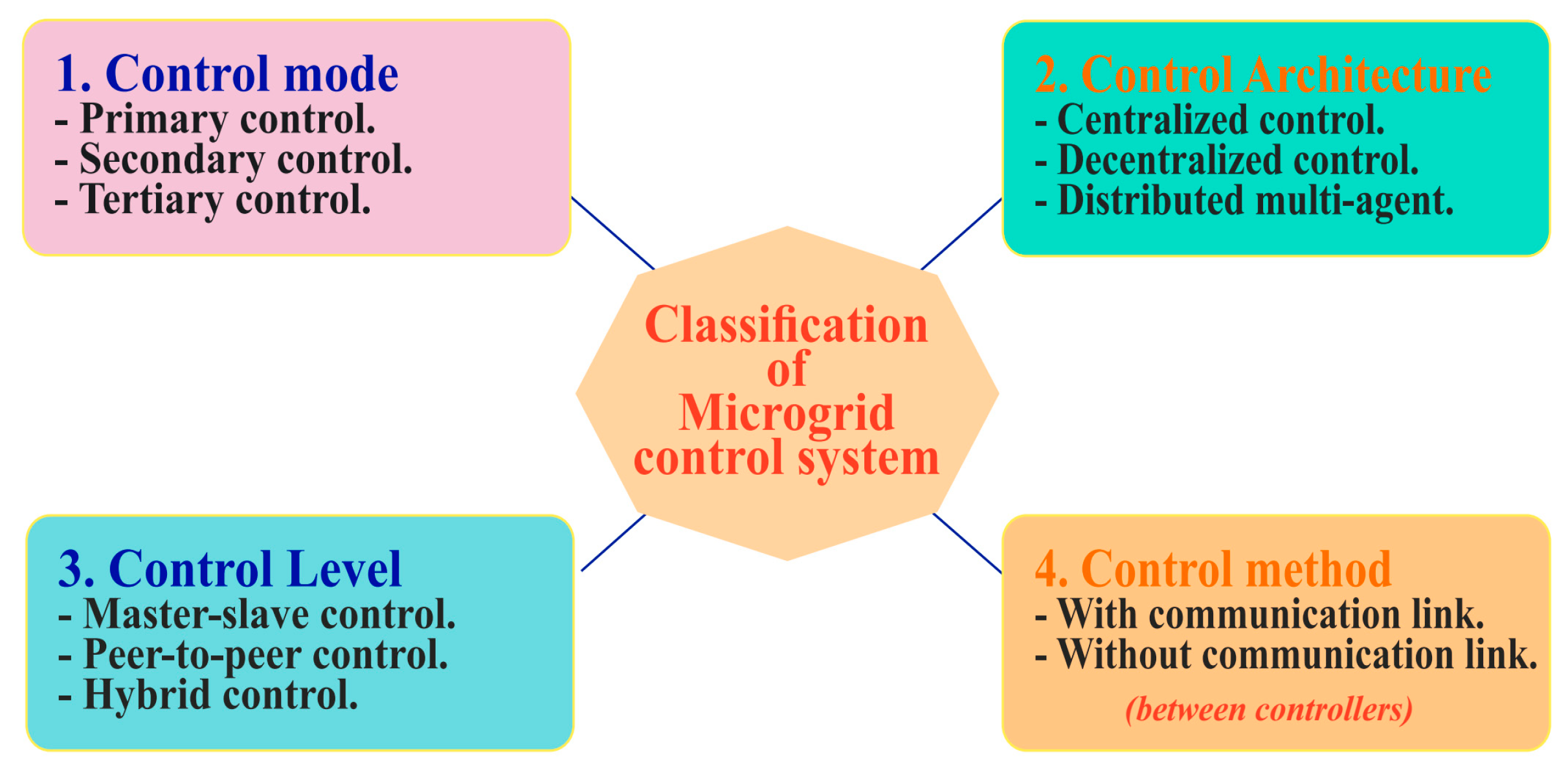
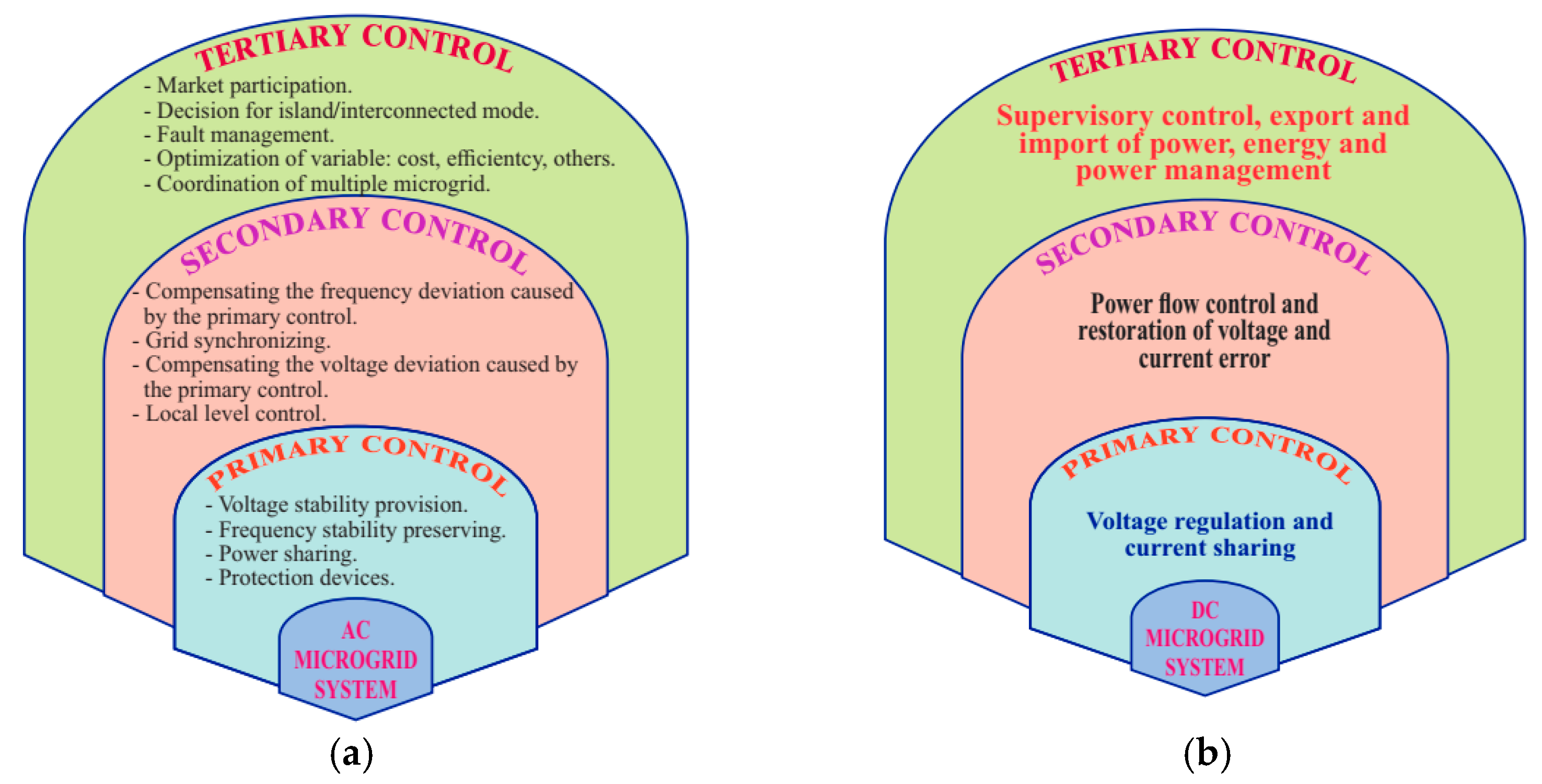
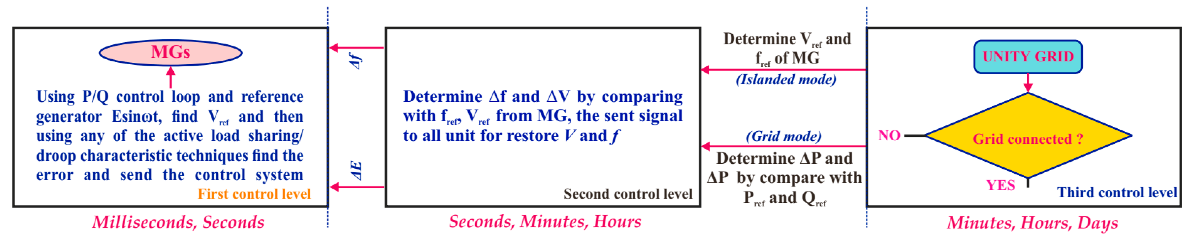
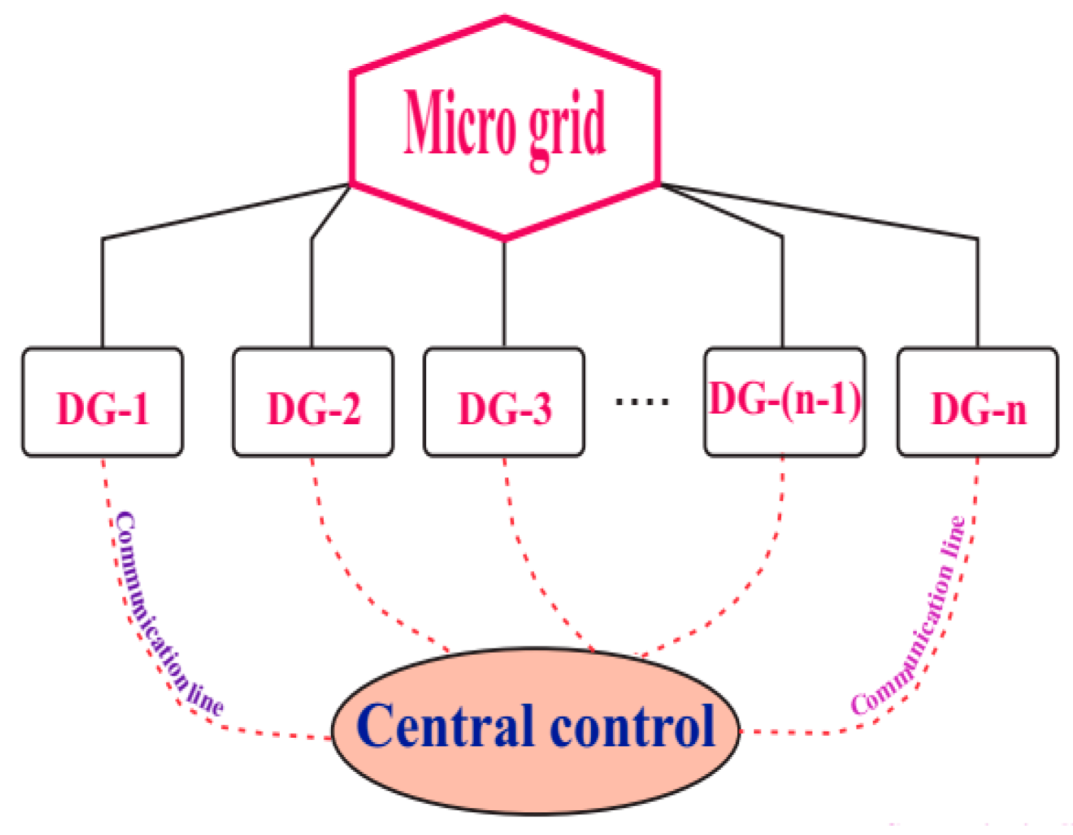
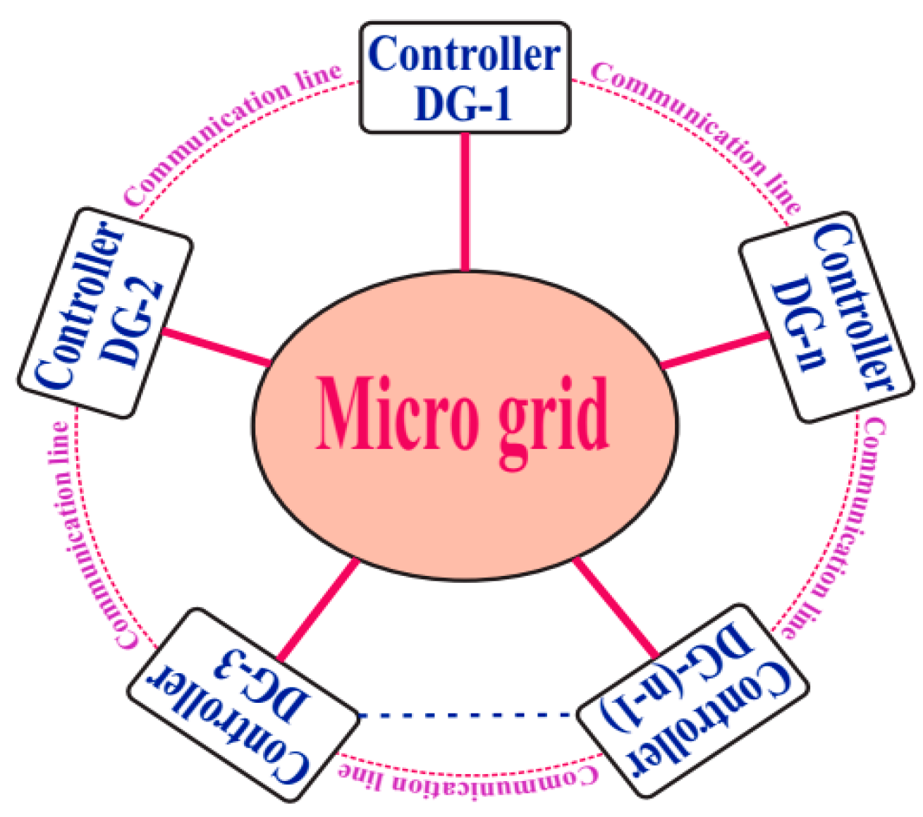
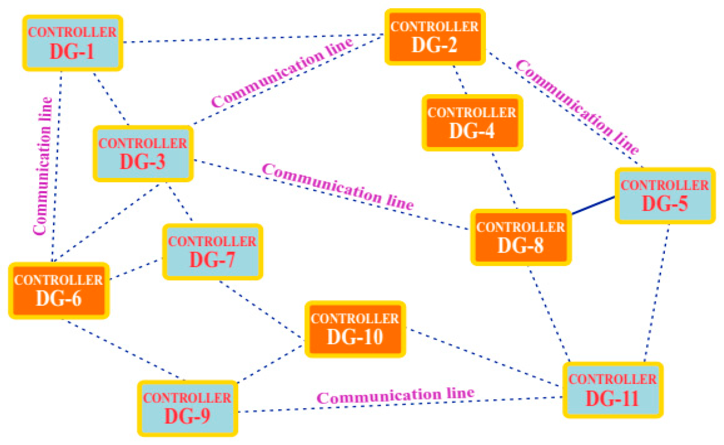
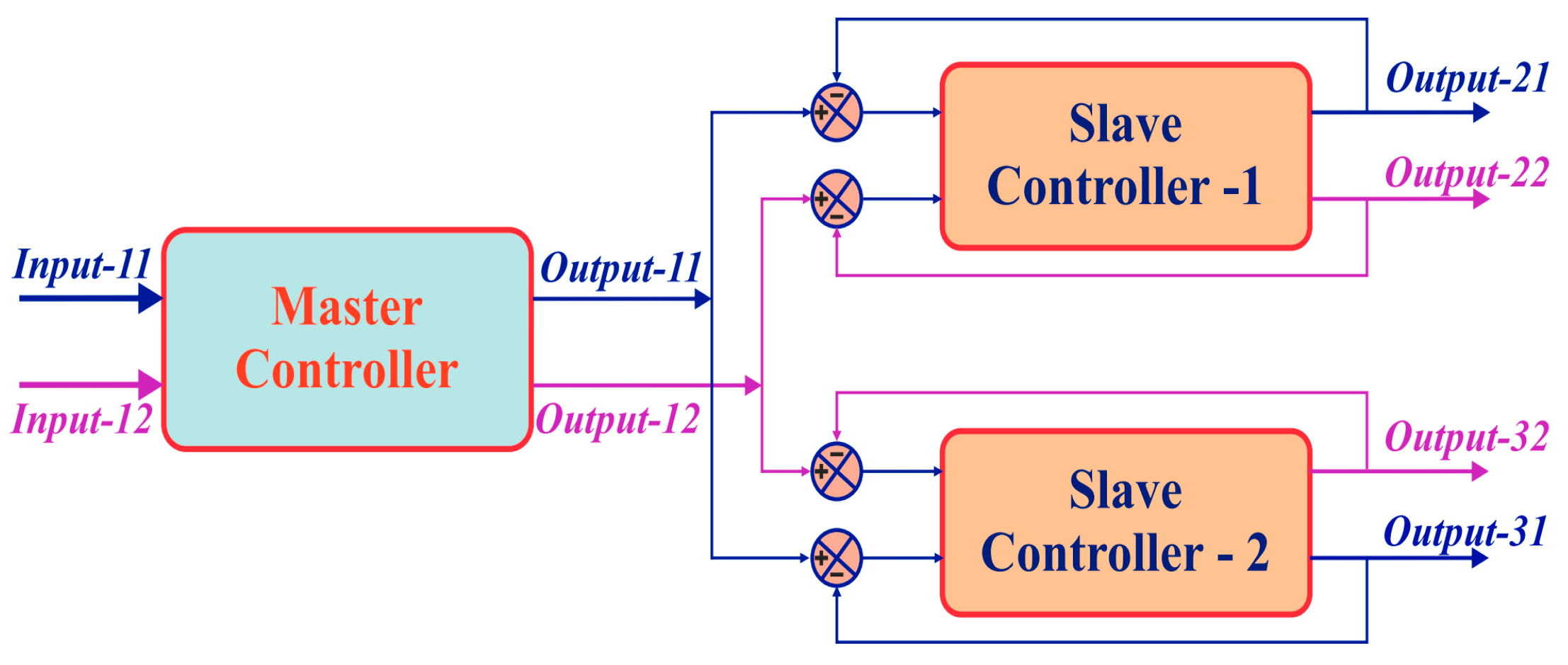
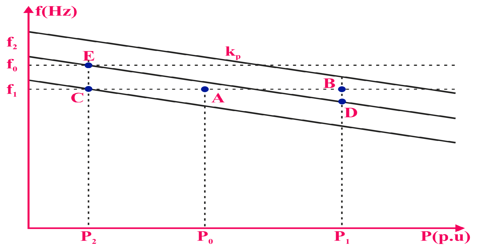
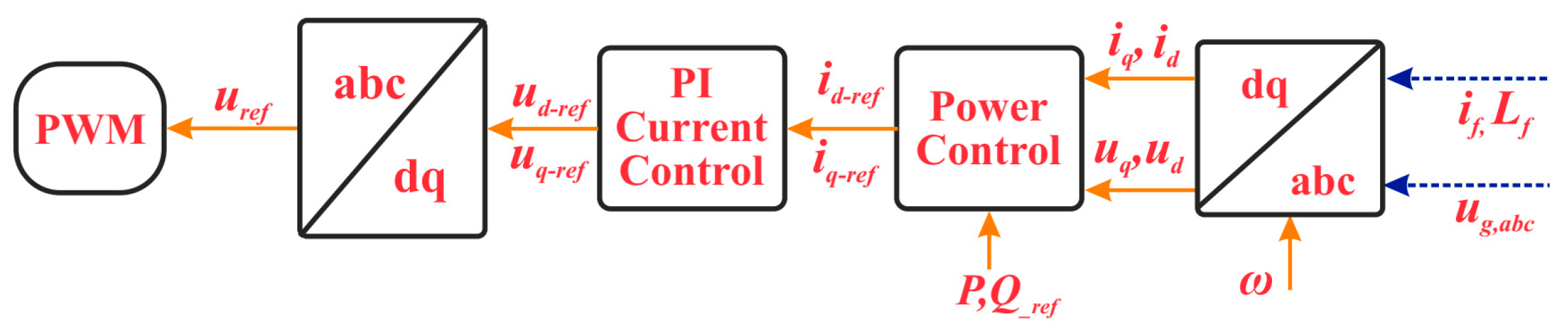
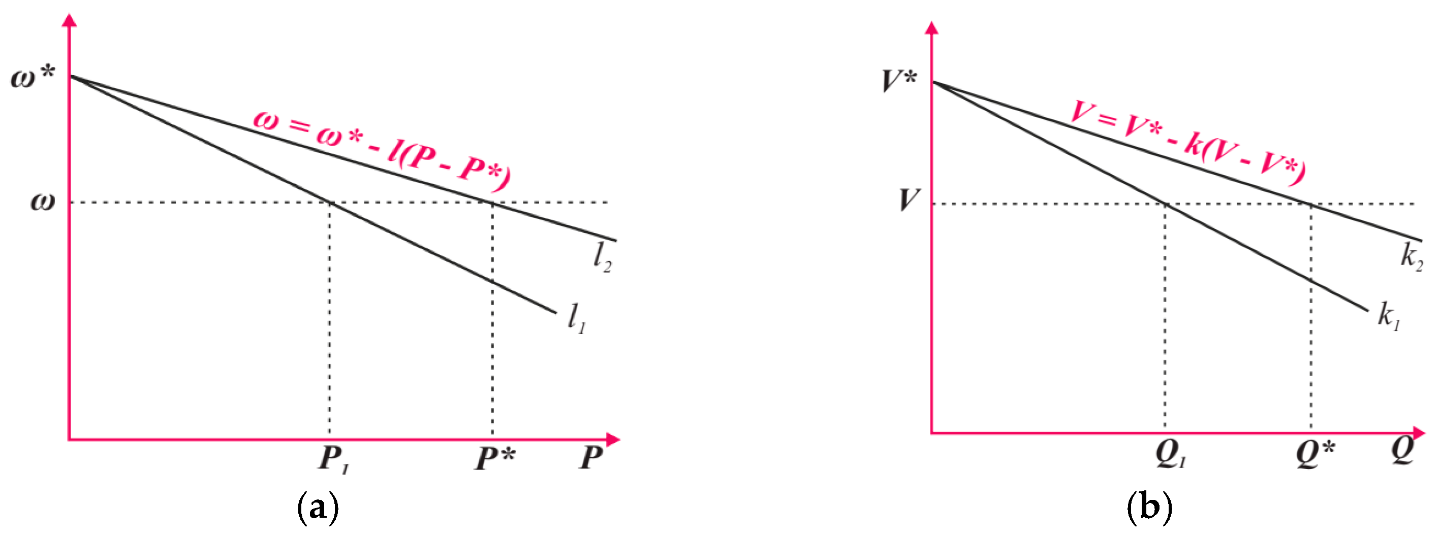
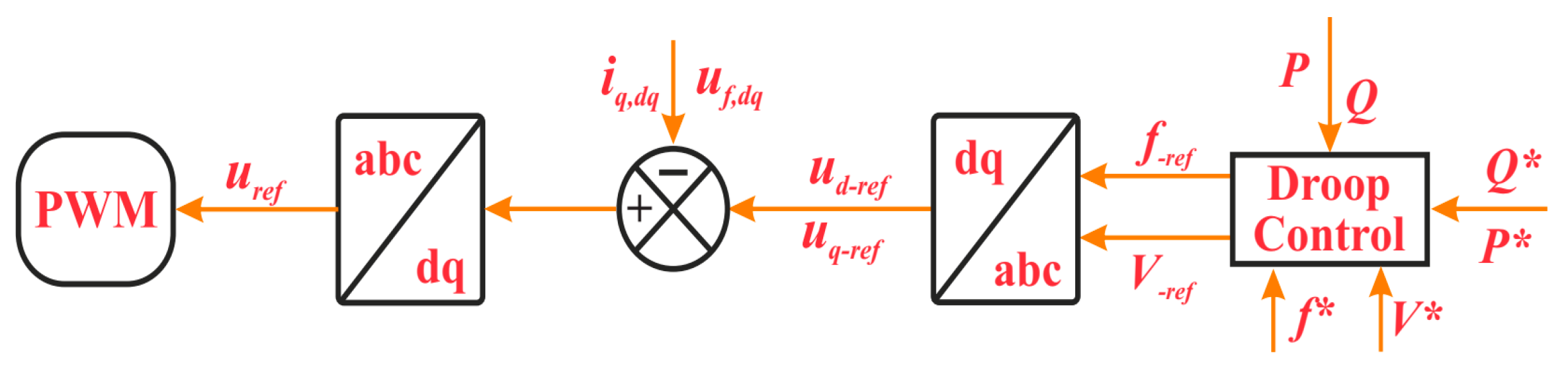
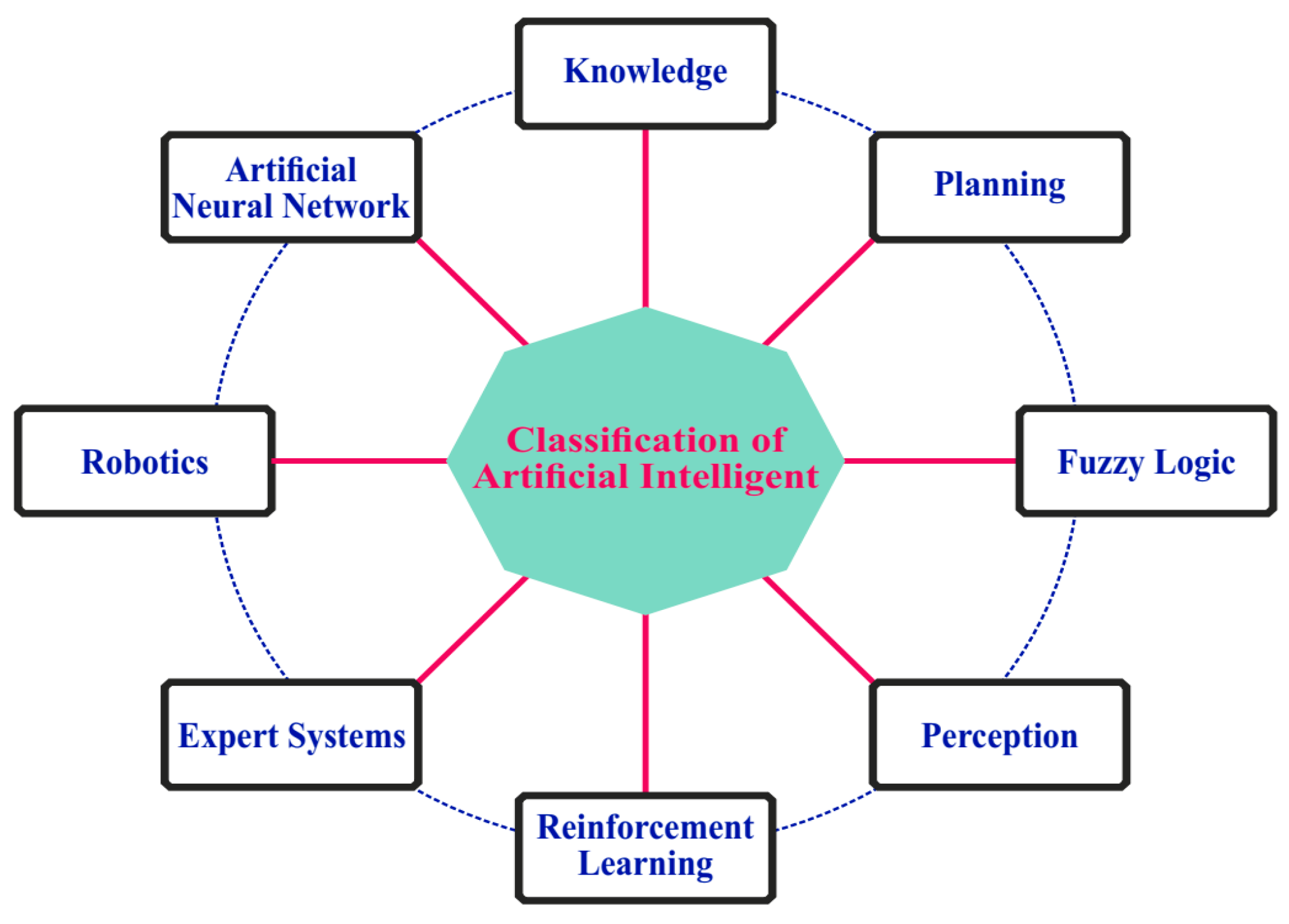
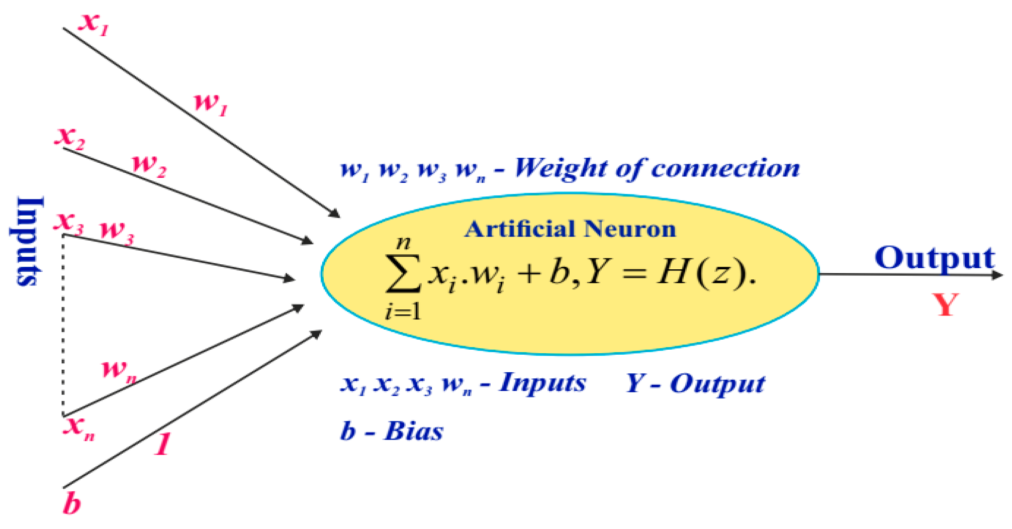
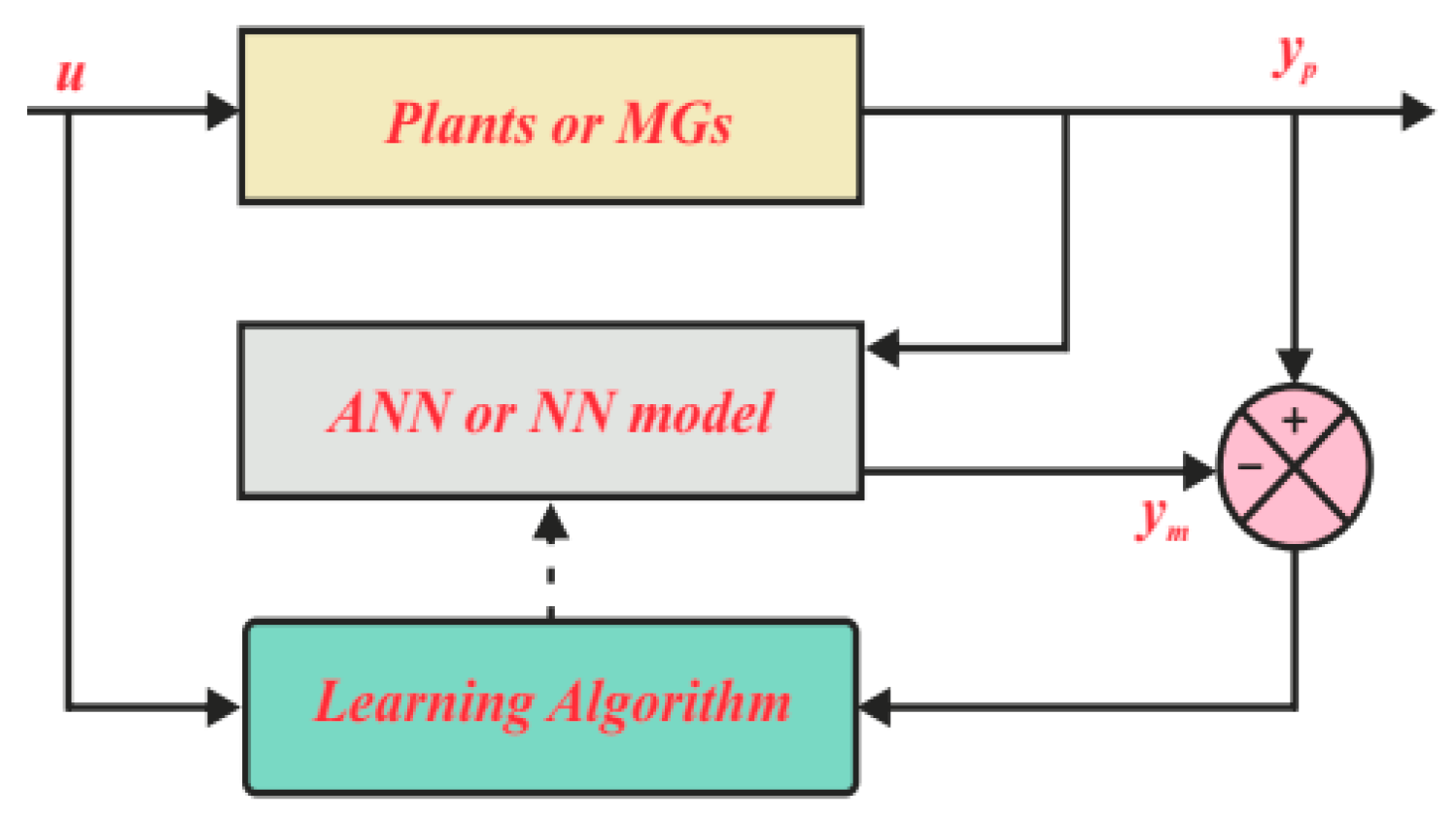


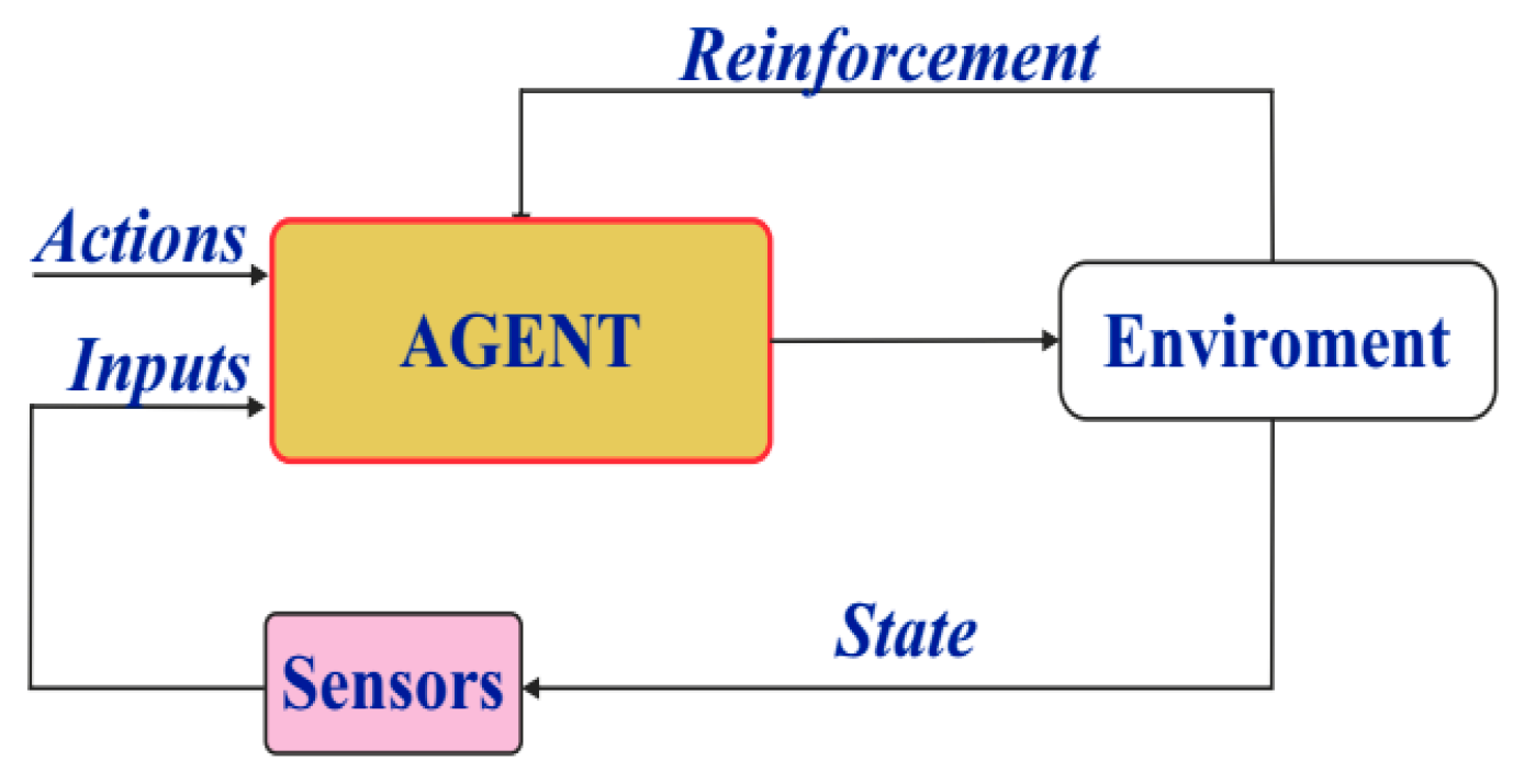
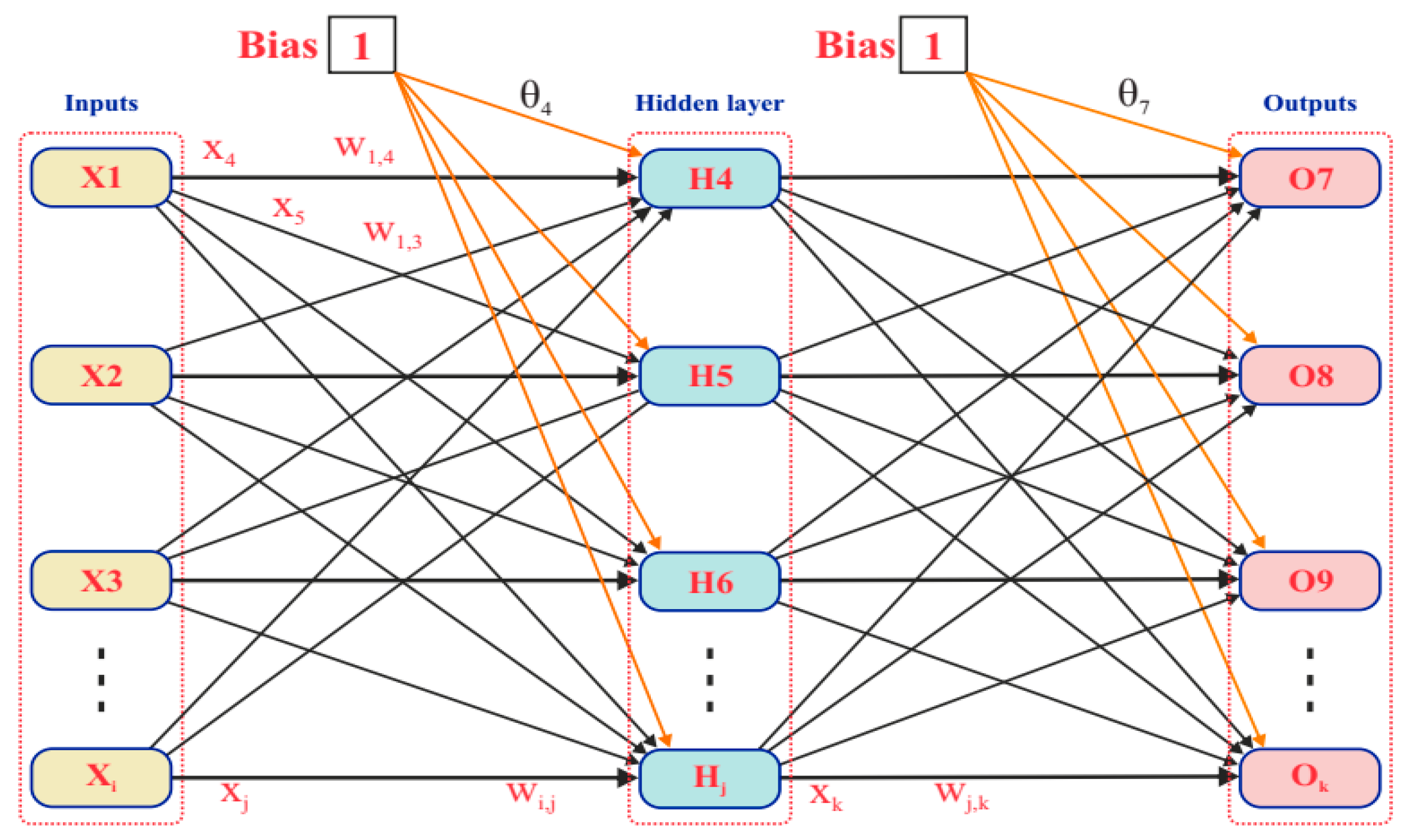

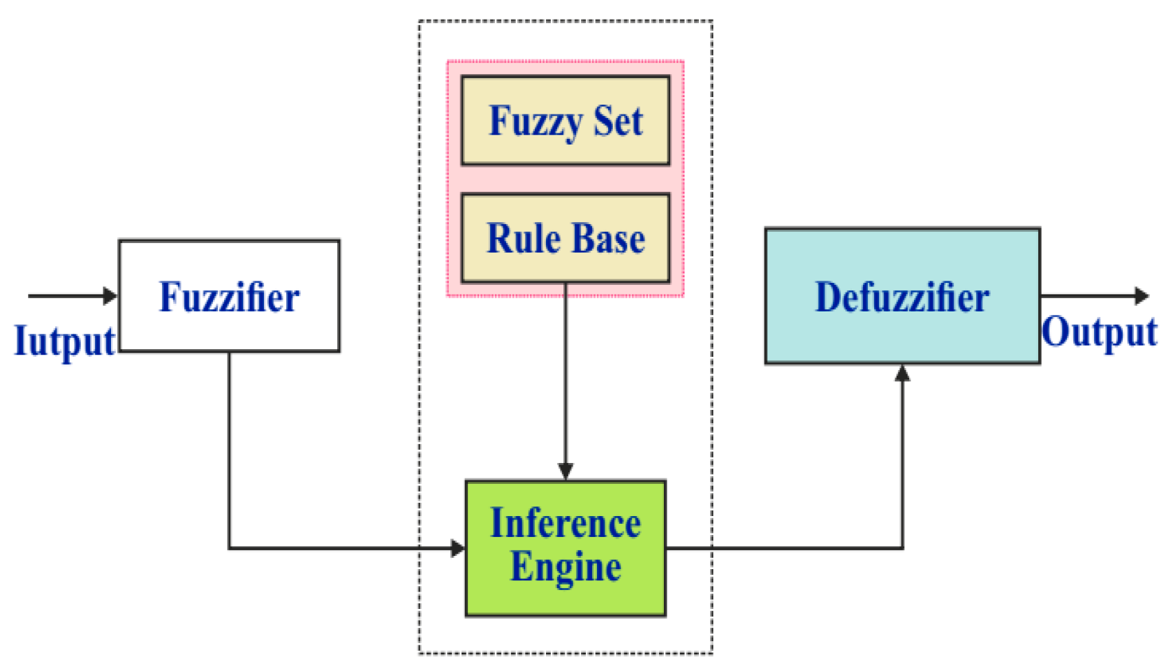
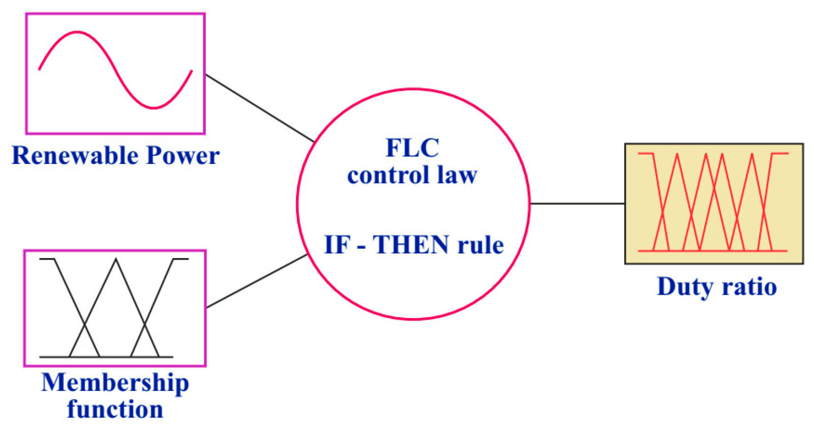
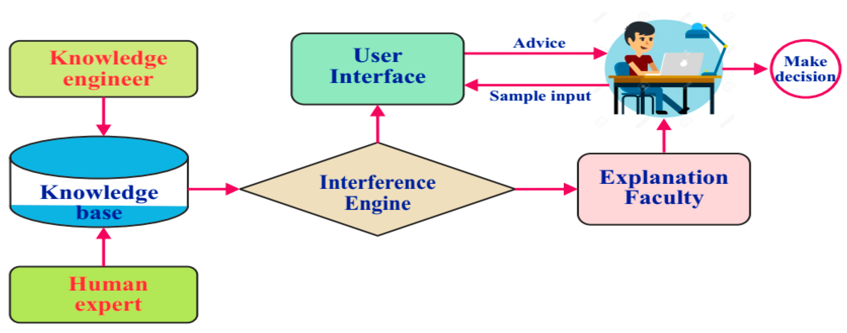

Disclaimer/Publisher’s Note: The statements, opinions and data contained in all publications are solely those of the individual author(s) and contributor(s) and not of MDPI and/or the editor(s). MDPI and/or the editor(s) disclaim responsibility for any injury to people or property resulting from any ideas, methods, instructions or products referred to in the content. |
© 2024 by the authors. Licensee MDPI, Basel, Switzerland. This article is an open access article distributed under the terms and conditions of the Creative Commons Attribution (CC BY) license (https://creativecommons.org/licenses/by/4.0/).