Article

Mechanical Behavior of Sediment-Type High-Impurity Salt Cavern Gas Storage during Long-Term Operation

1
PipeChina Energy Storage Technology Co., Ltd., Shanghai 200122, China
2
State Key Laboratory of Geomechanics and Geotechnical Engineering, Institute of Rock and Soil Mechanics, Chinese Academy of Sciences, Wuhan 430071, China
3
University of Chinese Academy of Sciences, Beijing 100049, China
4
Jiangsu Suyan Jingshen Co., Ltd., Huai’an 223200, China
*
Author to whom correspondence should be addressed.
Energies 2024, 17(16), 3983; https://doi.org/10.3390/en17163983
Submission received: 9 July 2024 / Revised: 2 August 2024 / Accepted: 10 August 2024 / Published: 12 August 2024
(This article belongs to the Special Issue Advanced Energy Storage Technologies and Applications (AESAs))

Abstract

:
With the development of salt cavern gas storage technology, the construction of large-scale salt cavern gas storage using sediment voids is expected to solve the problems of low effective volume formation rate and poor construction economy of high-impurity salt mines. At present, there are few studies on the long-term operational mechanical behavior of salt cavern gas storage under the influence of sediment accumulation. The present paper studies the influence of sediment height, particle gradation, and operating pressure on the stability of salt caverns by constructing a coupling model of sediment particle discontinuous medium and surrounding rock continuous medium. The continuous–discontinuous coupling algorithm is suitable for analyzing the influence of sediment height and particle gradation on the creep shrinkage of salt caverns. The increase in sediment height slows down the creep shrinkage of the cavern bottom, which strengthens the restraining effect on the surrounding rock of the cavern. As a result, the position of the maximum displacement of the surrounding rock moves to the upper part of the cavern. The sediment particle gradation has little effect on the cavern volume shrinkage rate. The greater the coarse particle content, the smaller the cavern volume shrinkage rate. The greater the operating pressure, the more conducive to maintaining the stability of the cavern. This situation slows down the upward movement of the sediment accumulation and increases the gas storage space in the upper part of the cavern. The obtained results can provide a reference for evaluating the long-term operational stability of sediment-type high-impurity salt cavern gas storage.

1. Introduction

Deep salt mines serve as excellent geological structures for underground energy storage [1,2]. Globally, hundreds of salt cavern gas storage facilities have been constructed [3,4]. In China, notable examples include the Jintan salt cavern gas storage, Jintan salt cavern compressed air energy storage, and Jianghan salt cavern gas storage [5]. While salt cavern gas storage both domestically and internationally is typically constructed in high-impurity salt mines, most salt mines in China are characterized by low-grade, high-impurity salt with numerous interlayers [6]. In high-impurity salt mines, the traditional water solution mining technology for salt cavern gas storage results in a significant accumulation of sediment at the cavern bottom [7]. This, in turn, limits the capacity of large-scale salt cavern gas storage after the injection of gas, leading to a low rate of salt dissolution and poor economic feasibility for cavern construction [8,9]. As shown in Figure 1, the conventional de-brining practice solely focuses on removing free brine in the upper cavern space, neglecting the brine trapped within the pores. Using sediment voids for gas storage may resolve this issue [10]. This method involves the establishment of an additional discharge well, which would be interconnected with the existing salt cavern.
The cavern formed by water solution mining in high-impurity layered salt rock contains numerous interlayers and insoluble particles. Fragmentation and expansion of these particles create voids larger than typical rock or soil pore spaces, allowing brine and fine particles to be transported within the sediment voids [11]. During the long-term operation of salt cavern gas storage, the cavern experiences creep and shrinkage. This leads to the extrusion and reduction of voids by the surrounding rock. The greater the deviatoric stress between the cavern and the surrounding rock, the more pronounced the contraction. However, as void compression decreases, support from the sediment particles increases, eventually reaching equilibrium without the sediment particles compacting into a solid body [12].
Salt cavern gas storage is a critical facility for natural gas. The long-term stability of the salt cavern is essential for its safe operation. Recently, numerical simulation technology has been pivotal in stability analysis [13], design optimization [14], and risk assessment [15] of salt cavern gas storage. Chen et al. [16] utilized numerical simulation results to investigate the feasibility of converting abandoned salt caverns into underground natural gas storage facilities. Liu et al. [17] analyzed the impact of various cavern morphologies on the deformation characteristics of salt cavern gas storage through numerical simulation, providing a foundation for the safety analysis of salt cavern storage groups. Zhao et al. [18] evaluated the feasibility of constructing a salt cavern gas storage facility at a depth of over 2700 m in the Ningjin Salt Mine, providing key parameters such as optimal cavern morphology, cavern dimensions, and operating pressure. Besides numerical simulation studies on salt cavern stability, related research also addresses the impact of sedimentation on the morphology of salt cavern gas storage. Li et al. [19] examined the influence of insoluble matter on cavern morphology during cavern creation in high-impurity salt rocks, derived the accumulation equation of insoluble matter, and integrated it into software to simulate the cavern creation in high-impurity salt mines. Xue et al. [20] analyzed the causes of twelve irregular salt caverns in China, identifying geological factors, construction technology, and pipeline damage as three key factors. Currently, the impact of sedimentation on salt cavern stability is rarely considered during the long-term operation of salt cavern gas storage facilities. Detailed studies on the accumulation characteristics of sediment particles are lacking. Therefore, it is crucial to research the long-term mechanical behavior of sediment-type salt cavern gas storage.
To close the gap in the research mentioned in the previous paragraph, a study on the coupling effect between sediment particles and the surrounding rocks of the cavern is conducted to analyze the influence of sediment accumulation on the long-term operational stability of the salt cavern gas storage. The built-in particle flow code (PFC) in Fast Lagrangian Analysis of Continuum (FLAC 6.0) software is utilized to establish a continuous–discontinuous coupling model. The effects of sediment height, particle gradation, and operating pressure on the volume shrinkage rate of the cavern and the deformation of the surrounding rock are studied. This aims to provide a reference for evaluating the long-term stability of high-impurity sediment-type salt cavern gas storage.

2. Numerical Model

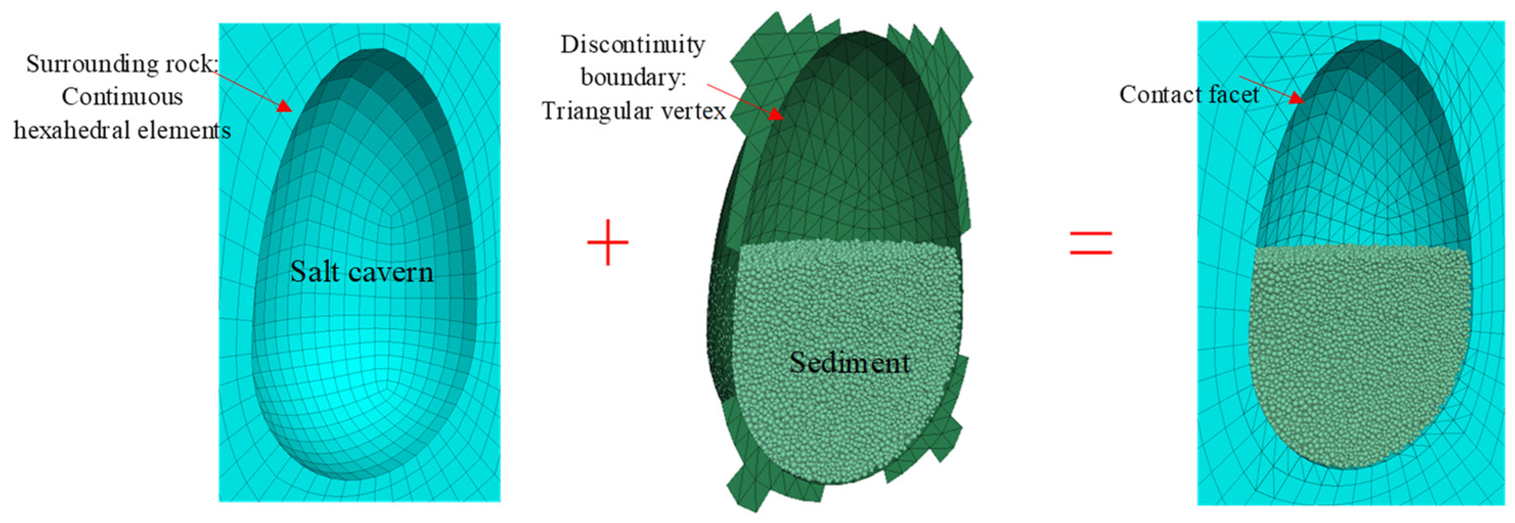
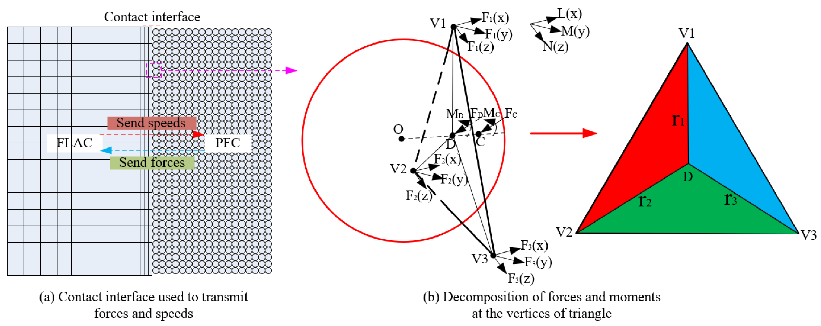
2.1. Continuous–Discontinuous Coupling Theory

FLAC is a numerical analysis method used to simulate the mechanical behavior of materials in continuous media, based on the explicit finite difference method. It is widely used in studying salt cavern stability [21], tightness [22], and intrinsic models of salt rock creep [23]. PFC is a numerical analysis tool designed to study the fine-scale mechanical response of particles, providing data that is challenging to obtain through experiments [24]. It plays a significant role in studying the mechanical properties and fatigue creep of salt rock. Sediment accumulation consists of numerous insoluble particles that undergo significant deformation under compressive loading [25]. Conventional continuous medium research methods struggle to characterize these deformation properties. Thus, the simulation and computation advantages of both FLAC and PFC can be utilized to analyze the long-term support effect of sediment on the surrounding rock.
To enable interaction between the PFC particles and FLAC rocks, a coupled computing scheme must be established at the contact surface to transfer velocity and force information, facilitating information exchange between discrete particles and continuous elements. As shown in Figure 2, the coupled computing principle involves transferring velocity information from the continuous medium to the discontinuous medium through the contact surface, while the discontinuous medium transfers force information by altering displacement to the continuous medium [26,27]. Force transfer on the contact surface is achieved by decomposing the force into a triangular vertex on the contact surface using the coordinates of the contact particle centers. Velocity and displacement information is transferred through the triangular vertex as a function of computational time. Interaction occurs through the transfer of force and displacement information via contact forces and moments on the vertices of the triangular vertex. For coupling calculations, the contact surface is a PFC wall composed of triangles, with vertex velocities related to position and computation time. Contact forces and moments applied to the contact surfaces are converted to vertice velocities on the triangular surfaces using the equivalence method. On the continuous–discontinuous contact surface, the contact forces and moments are balanced using the following expression:
F i × r i = M C + F C × L
F i = F C
where C is the contact position, D is the closest point on the wall facet, V i is the triangular vertice, r i is the distance between the triangle vertice and the closest point, M C and F C are the moment and contact force at the contact point, F i is the force applied at the vertex; and × is the cross-product.

2.2. Model Establishment

The numerical model was analyzed using an ideal salt cavern shape, with a pear-shaped cavern and an internal accumulation of sediment particles. The lower part of the cavern is a hemisphere with a radius of 40 m. The upper part is a semi-ellipsoid with a long axis of 80 m and a short axis of 40 m, and the center of the cavern is located at a depth of 1000 m. Assuming that the influence of interlayers is not considered, the cavern is situated in a pure salt rock layer. The overall model is a rectangular body with dimensions of 1200 m long, 600 m wide, and 1200 m high. As shown in Figure 3, half of the model is used as the research object, considering the symmetry of the cavern. Boundary conditions were set according to the average density and depth of the rock layer. The overlying rock layer was simplified to a top load with a pressure of 11.2 MPa. Normal constraints were applied at the bottom and four face boundaries of the model. ANSYS 19.0 software was used to mesh the model as a whole [28]. To improve solving accuracy and efficiency, all hexahedral elements were used, and a radioactive mesh was employed to refine the perimeter of the cavern.
According to the change in force situation in the cavern from the original stratum to use sediment voids for gas storage, the initial stress of the model was first established. The initial stress of three-way isobaric pressure was established as the horizontal ground stress of the rock layer increased until it equaled the vertical ground stress due to the long-term creep of the salt rock. Ultimately, the rock layer below 433.2 m was in a state of hydrostatic pressure [29]. Then, the cavern was transiently excavated, and a brine gradient pressure was applied to the inner surface of the excavated cavern wall to simulate the brine-filled salt cavern [30]. The stress redistribution field after the cavern was excavated was then calculated. Finally, the particle accumulation generated by the PFC was embedded into the FLAC software. As shown in Figure 4, the detailed modeling process is described as follows:
(1)
Establish the cavern of sediment accumulation and generate a certain number of sediment particles. First, the PFC module is introduced into the FLAC software for coupling calculation. A certain gradation of sediment particles is generated in the cavern bottom regarding the particle parameters and assigned to the sediment particles (Table 1 and Table 2). Taking the brine buoyancy into account, the density of the sediment particles is set to the density of the solids minus the density of the brine [31]. Then, the sediment particles are accumulated by self-gravity in the cavern bottom.
(2)
Embed the excavated salt cavern model and the sediment particle accumulation in the same interface to achieve the coupled calculation of the continuous boundary of the surrounding rock and the discontinuous boundary of the particles. Then, delete the particles outside the boundary of the cavern and recalculate the stress redistribution after the cavern excavation.
(3)
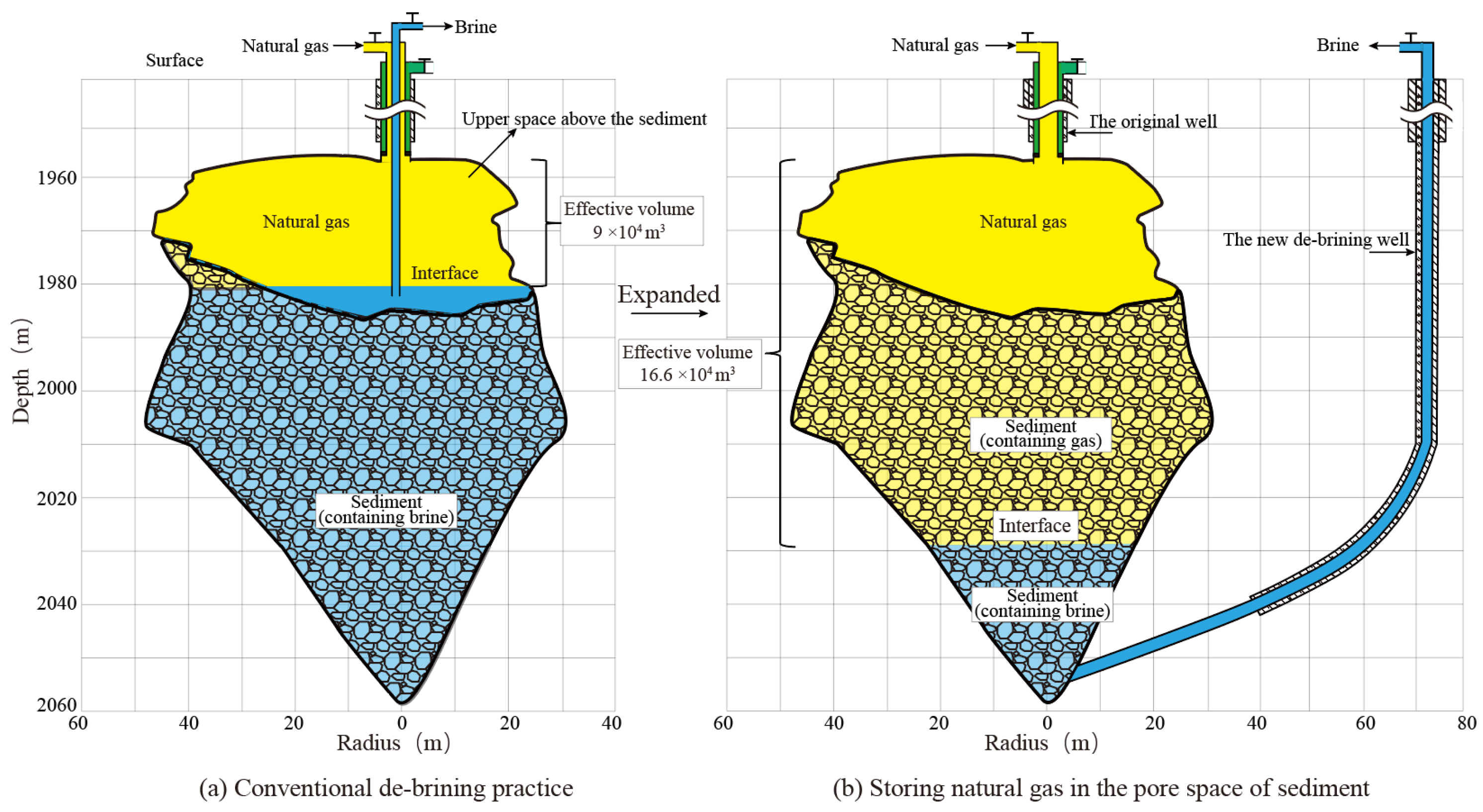
Apply different pressures to the cavern walls. Since the cavern is filled with natural gas during operation, the upper part of the cavern is subject to gas pressure, and the lower part is subject to the combined action of brine and sediment pressure. Brine pressure varying with depth is applied to the cavern wall, and the sediment is modeled by the particle accumulation generated by the PFC 5.0 software.
(4)
Set the creep time to start the calculation. According to the creep parameters in the paper [12] and assigning them to the salt rock (Table 3), a combination of the viscoelastic Norton–Hoff model and Mohr–Coulomb elastoplastic model is used to calculate the coupled creep of the sediment particles in the cavern and the surrounding rock [32]. The timestep of the creep model is 5 × 10⁻⁶, while the timestep of the particle model is 1.0 × 10⁻⁴. When the creep of the surrounding rock is calculated 20 times, the displacement information is transmitted to the particles and the contact force changes between particles. Then, the contact force information is transmitted back to the surrounding rock.
(5)
To analyze the effects of the salt cavern’s sediment height, particle gradation, and operating pressure on the volume shrinkage of the cavern and the deformation of the surrounding rock, ten numerical simulation schemes were carried out (Table 4).
Figure 3. Numerical model of sediment-type cavities.
Energies 17 03983 g003
Figure 4. A coupled model of surrounding rock and discontinuity boundary.
Energies 17 03983 g004
Table 1. Parameters of sediment particles.
Density
/kg·m−3
Effective Modulus
/GPa
Normal Critical Damping RatioDampInitial
Porosity
Friction CoefficientRadius
/m
2450100.70.70.40.50.5
Table 2. Parameters of boundary wall.
Normal Stiffness
/MPa
Shear Stiffness
/MPa
Damp Normal RatioFriction
Coefficient
1001000.50.1
Table 3. Physical and mechanical parameters of salt rock.
LithologyElastic
Modulus
/GPa
Poisson’s RatioCohesion
/MPa
Friction Angle
Tensile Strength
/MPa
Salt rock50.32.0300.6
Table 4. Numerical simulation schemes.
No.Sediment Height
/m
Operating pressure
/MPa
Particle Gradation
1010Uniform distribution
23010Uniform distribution
36010Uniform distribution
49010Uniform distribution
56010More coarse particles and less fine particles
66010Less coarse particles and more fine particles
7604Uniform distribution
8606Uniform distribution
9608Uniform distribution

3. Results and Analysis

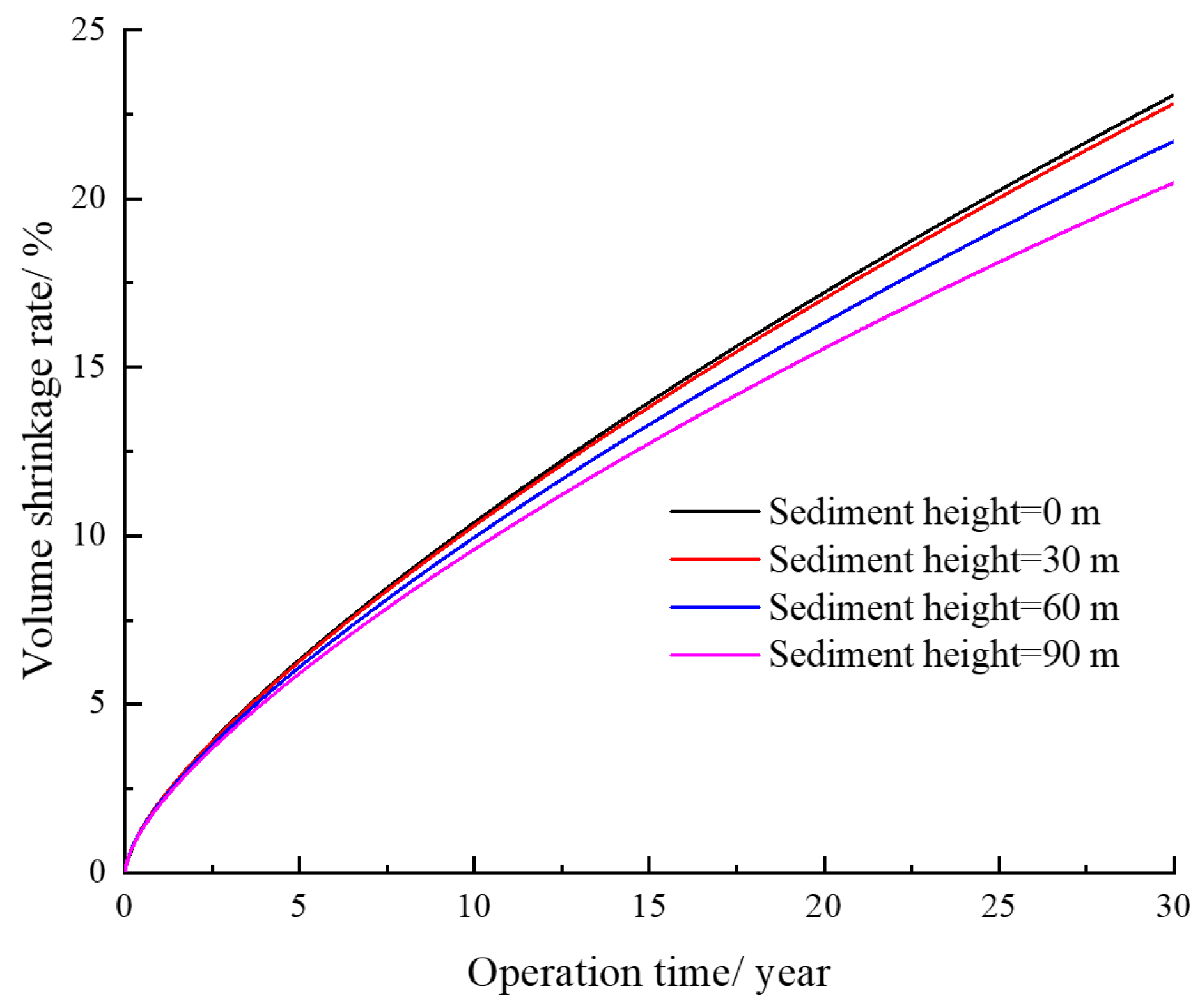
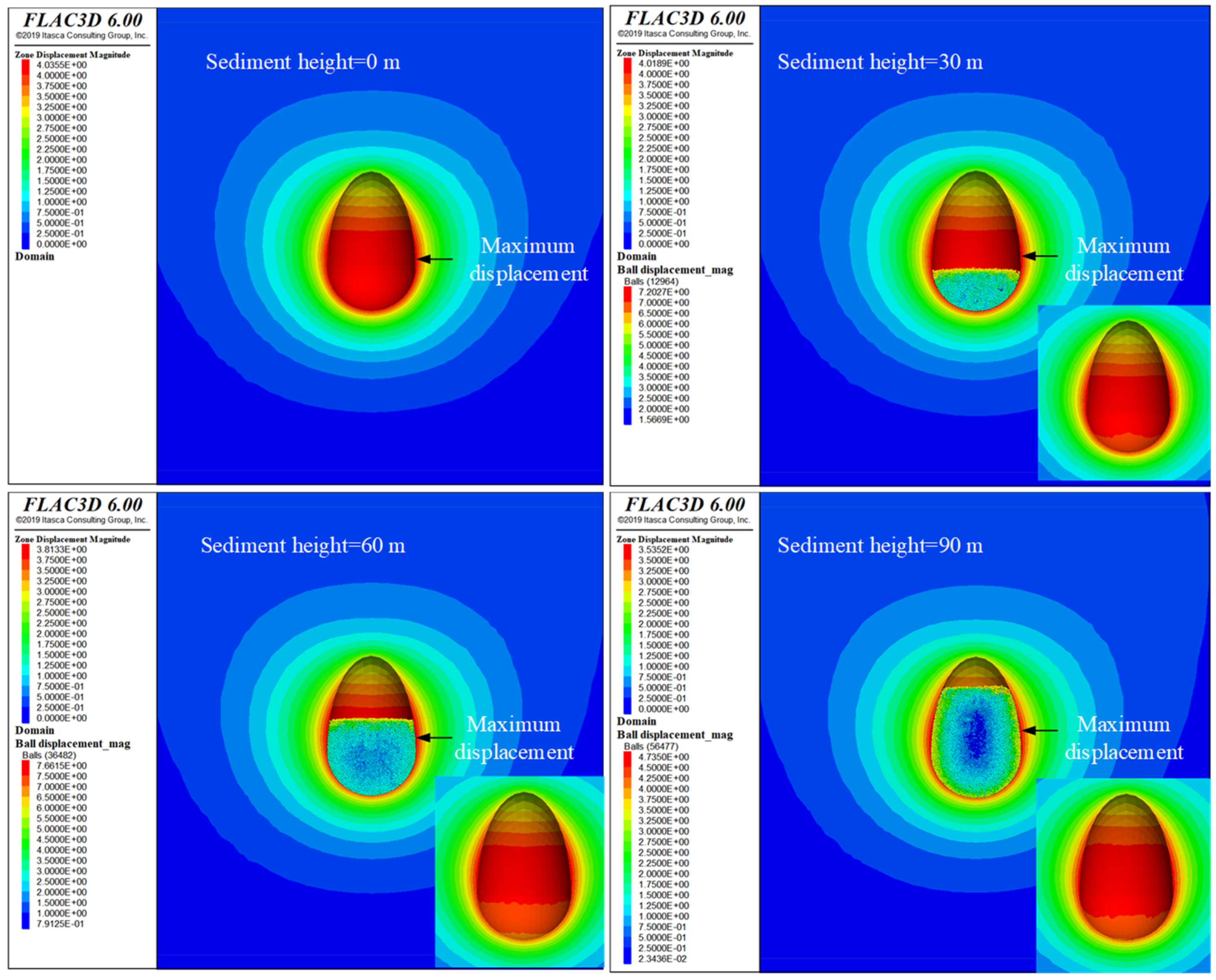
3.1. Sediment Height

Figure 5 presents the volume shrinkage rates of the salt cavern at different sediment heights. As the creep time increases, the cavern volume shrinkage gradually increases. As the sediment height increases, the cavern volume shrinkage gradually decreases. This indicates that the sediment height has an inhibitory effect on the creep contraction of the salt cavern. To ensure the availability of salt cavern gas storage, the cavern volume shrinkage rate due to creep over 30 years should generally be no more than 30% [33]. When the operating pressure is maintained at 10 MPa, the volume shrinkage due to cavern creep over 30 years is less than 30%.
Figure 6 presents the displacement contours of the surrounding rock for 30 years of operation at different sediment heights. It can be seen that under constant internal pressure, the maximum displacement of the surrounding rock gradually decreases as the sediment height increases. With sediment heights of 0, 30, 60, and 90 m, the maximum displacement around the cavern over 30 years of operation is 4.036, 4.019, 3.813, and 3.535 m, respectively. It is evident that the higher the sediment accumulation, the stronger the inhibition of sediment particles on the surrounding rock, particularly in the sediment-accumulated area, where rock displacement is significantly reduced. The maximum displacement around the cavern occurs in the middle, but as the sediment height increases, the maximum displacement tends to move upward. This occurs because higher sediment accumulation enhances support at the bottom of the cavern due to the self-weight of the particles, causing the maximum displacement to shift upward.

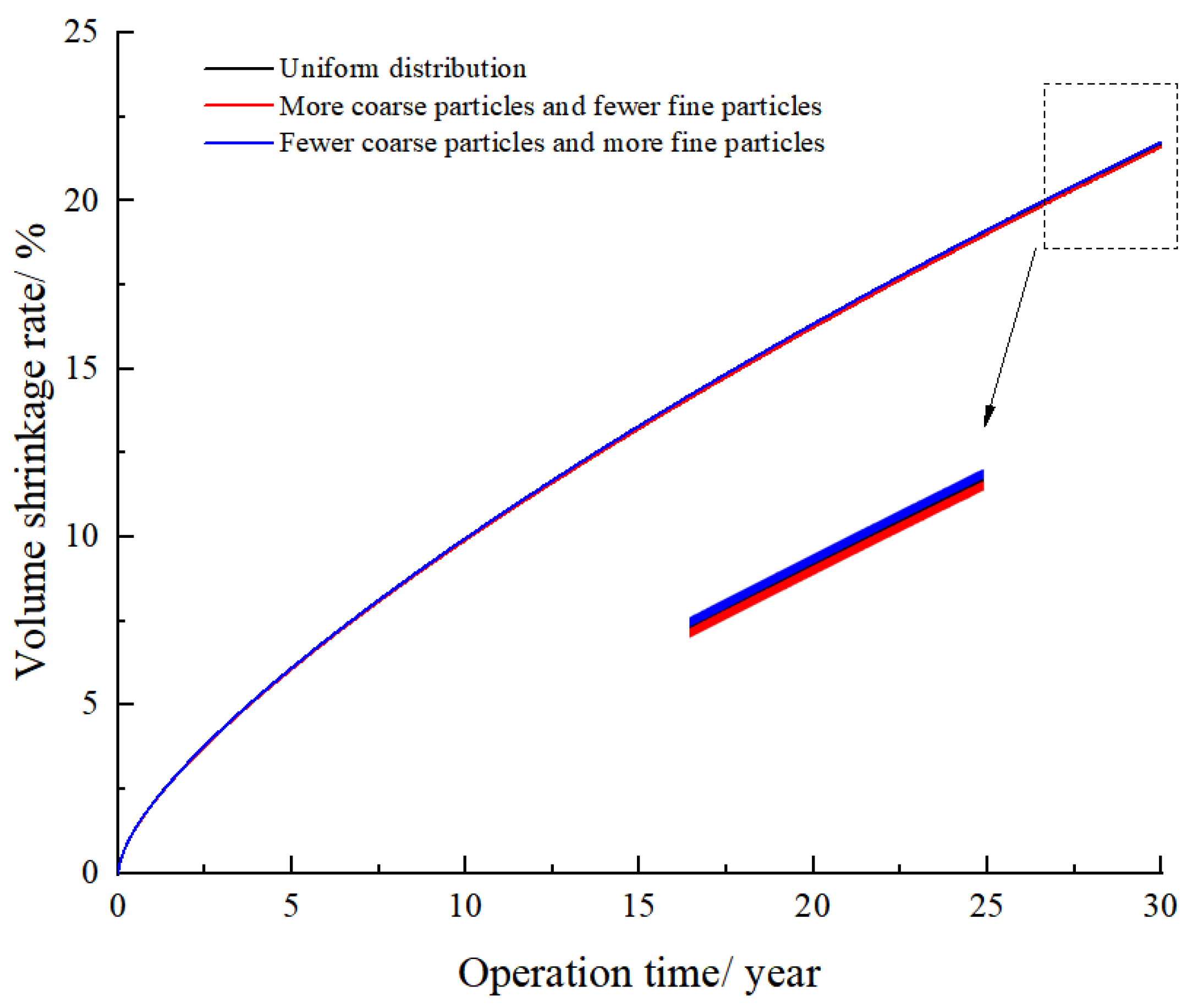
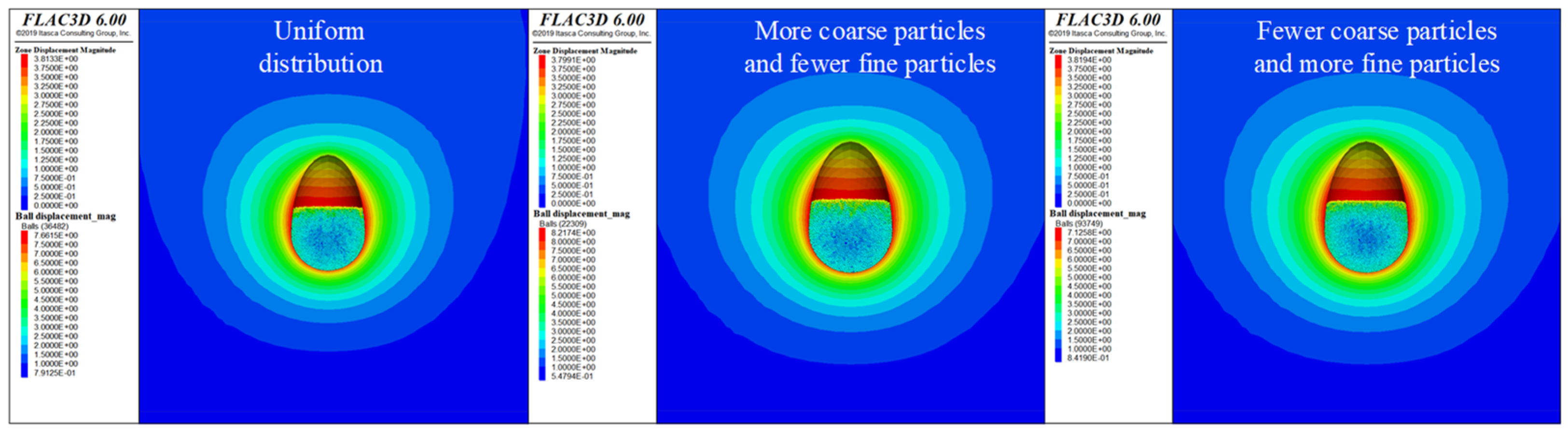
3.2. Particle Gradation

In this section, three types of salt sediment particle gradation curves—uniform distribution, more coarse particles and fewer fine particles, and fewer coarse particles and more fine particles—are used to simulate the effect of different sediment particle gradations on cavern stability. Figure 7 presents three types of salt sediment particle gradation curves for simulation. Figure 8 presents the volume shrinkage rates of the cavern for 30 years of operation at different sediment particle gradations. The volume shrinkage rates of three types of salt sediment particle gradation, more coarse particles, uniform distribution, and fewer coarse particles, are 21.61%, 21.70%, and 21.74%, respectively. Higher coarse particle content results in greater cavern volume shrinkage, but particle gradation has a smaller effect on volume shrinkage overall, indicating a minimal impact on packing density.
However, the numerical simulation primarily used spherical particles to characterize the shape of sediment particles, not considering the effect of irregularly shaped particles. Irregular particles lead to nested extrusion between packed particles, forming a more stable force chain structure. Thus, packing irregularly shaped particles provides stronger support to the surrounding rocks of the salt cavern. Displacement and cavern volume shrinkage follow the same trend: larger cavern volume shrinkage results in larger displacement. Figure 9 presents the displacement contours of surrounding rock for 30 years of operation at different sediment particle gradations. When the sediment contains more coarse particles and fewer fine particles, the maximum displacement is 3.805 m. When the sediment contains fewer coarse particles and more fine particles, the maximum displacement is 3.817 m, indicating a relatively small difference between the two gradations.

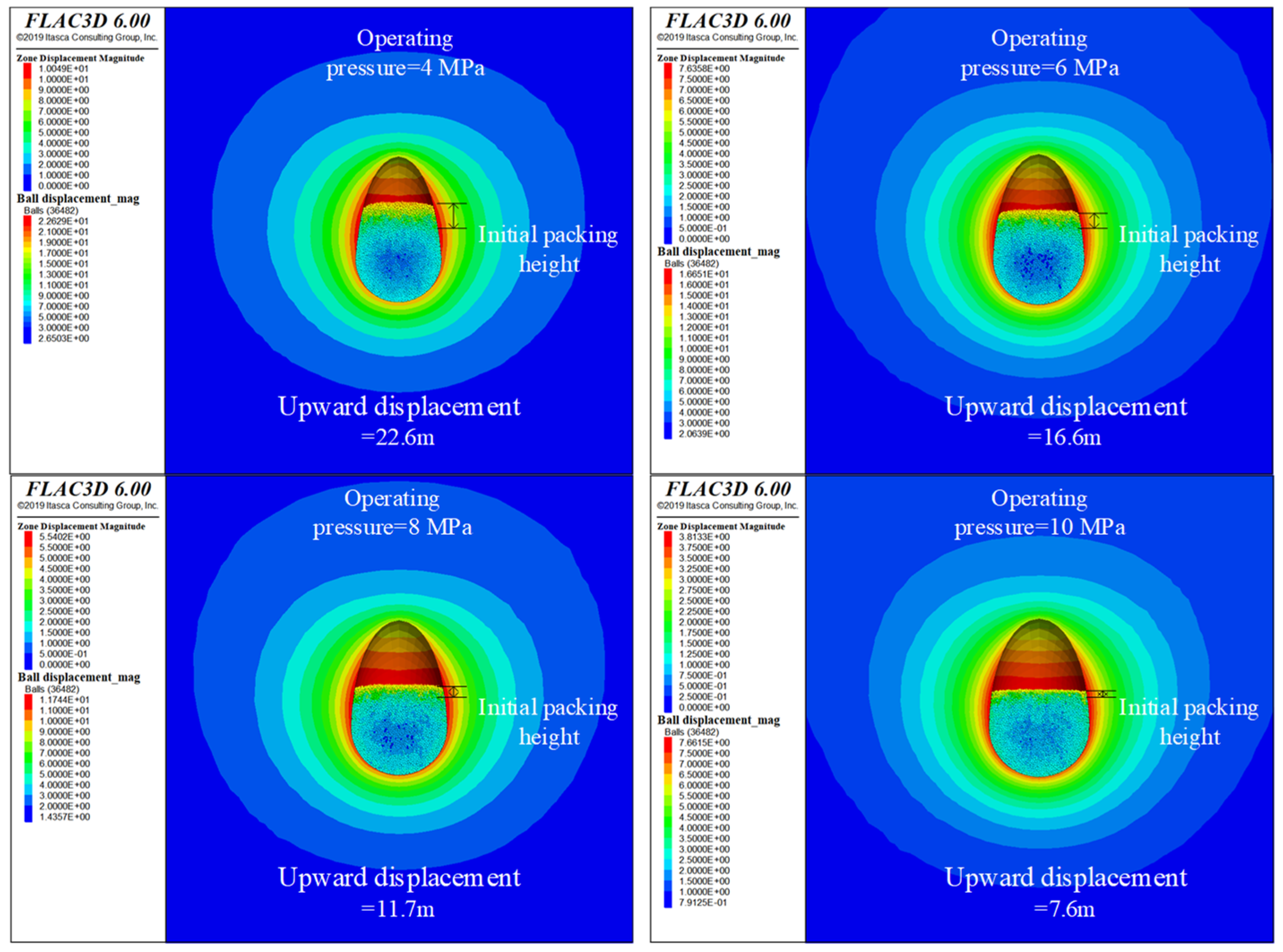
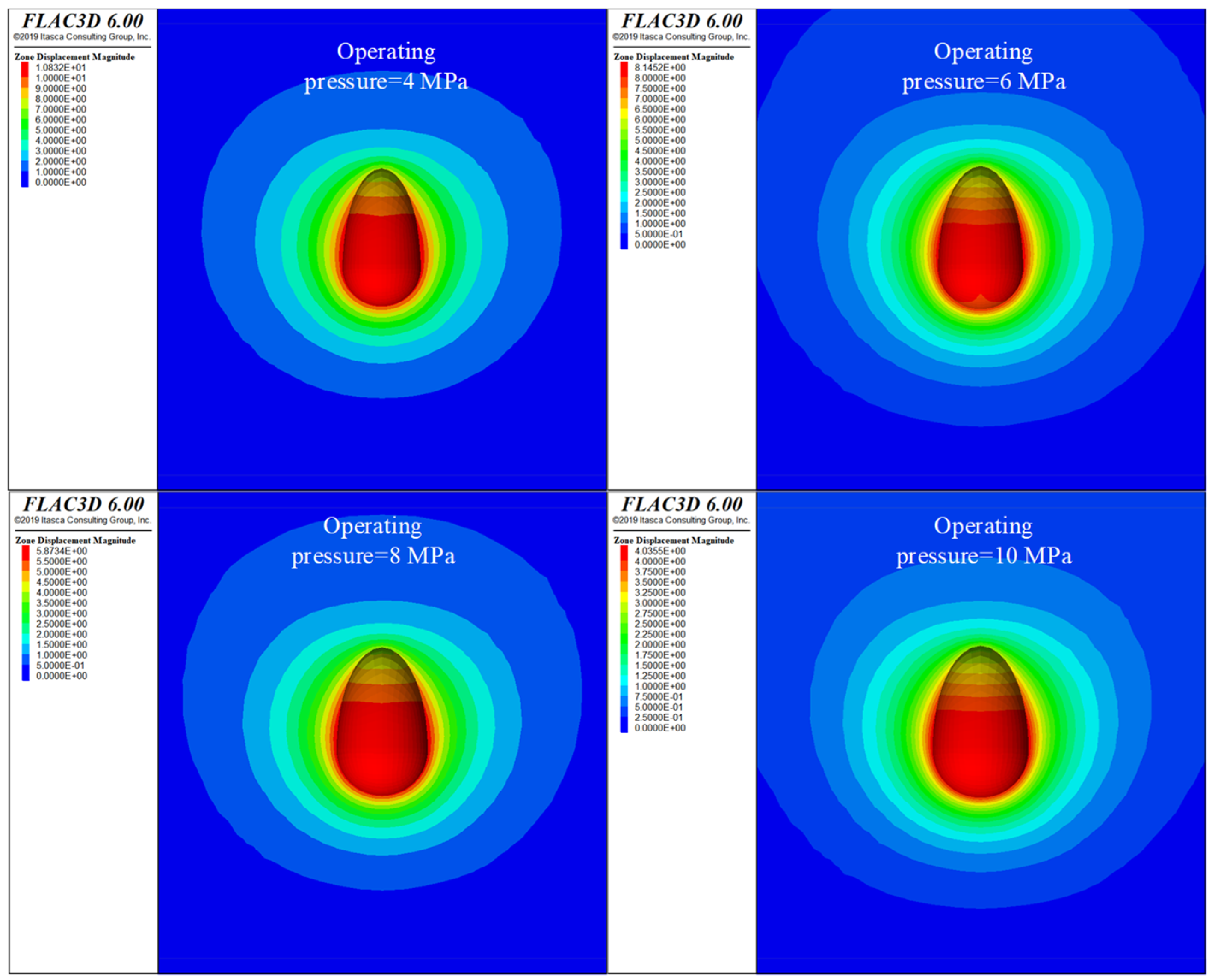
3.3. Operating Pressure

Given the simulation depth of the center of the salt cavern is 1000 m, the upper pressure is set to be no more than 18 MPa. The simulation uses constant operating pressures of 4, 6, 8, and 10 MPa to calculate the shrinkage of the cavern for 30 years of operation. Figure 10 presents the volume shrinkage rates of the salt cavern for 30 years of operation with and without sediment. It can be seen that higher operating pressure results in smaller volume shrinkage and reduces the maximum displacement. Figure 11 presents the volume shrinkage rates of the salt cavern for 30 years of operation at different operating pressures. For a salt cavern sediment height of 60 m and operating pressures of 4, 6, 8, and 10 MPa after 30 years of operation, the volume shrinkage rates were 49.9%, 40.1%, 30.4%, and 21.7%, respectively.
Figure 12 presents the displacement contours of the surrounding rock for 30 years of operation at different operating pressures with sediment. The maximum displacements of the cavern were 10.0, 7.6, 5.5, and 3.8 m, respectively, and the upward displacements of the salt cavern sediment body due to extrusion were 22.6, 16.6, 11.7, and 7.6 m, respectively. Figure 13 presents the displacement contours of surrounding rock for 30 years of operation at different operating pressures without sediment. Without sediment in the salt cavern, the maximum displacements of the cavern after 30 years of operation at operating pressures of 4, 6, 8, and 10 MPa are 10.8, 8.1, 5.8, and 4.0 m, respectively. The volume shrinkage rates of 53.9%, 42.9%, 32.4%, and 23.0%.
Comparing the differences in the maximum displacement of the cavern after 30 years of operation with and without sediment at operating pressures of 4, 6, 8, and 10 MPa reveals differences of 0.8, 0.5, 0.3, and 0.2 m, respectively. The differences in volume shrinkage were 4.0%, 2.8%, 2.0%, and 1.3%, respectively, indicating that the inclusion of sediment is more favorable for cavern stability. As operating pressure increases, the upward displacement of the sediment body slows down, the upper air storage space of the cavern increases, and the trends of the maximum displacement of the cavern perimeter and volume shrinkage of the sediment-containing salt cavern both gradually reduce.

4. Discussion

The operational parameters for salt cavern gas storage are influenced by the burial depth of the cavern, cavern morphology, and stratigraphic properties [34]. Numerical simulations are typically used to determine the upper and lower pressure limits for cavern operation [35]. The “Safety rules of salt cavern underground gas storage” [36] states that “the upper limit pressure of a salt cavern gas storage shall not exceed 80% of the rupture pressure of the formation at the shoe of the production casing and shall not be higher than 80% of the pressure of the overlying strata”.
The salt grade is a key factor affecting the accumulation height of insoluble sediment, with more sediment accumulating at the bottom of the cavern in high-impurity salt mines [36]. Therefore, different accumulation heights were used to comparatively analyze the effect of sediment height on the cavern stability. Generally, the maximum displacement around the cavern should not exceed 5–10% of the maximum cavern diameter, which is an indicator of surrounding rock damage [37]. A certain height of sediment in the salt cavern is beneficial for the stability of the surrounding rock. However, it reduces the net brine space in the upper part of the cavern. If the brine in the bottom sediment void can be partially discharged, the cavern mining space can be maximized.
The particle size distribution of sediment particles is influenced by the grade of the salt layer, stratigraphic distribution, and the process of brine extraction [38]. The size and distribution of sediment particles at the cavern bottom after water solution mining varies across regions, and the thickness of the salt layer and interlayer at different depths of the same salt mine also differs. This results in significant variations in the gradation of sediment particles accumulated at the cavern bottom. Therefore, it is difficult to use a uniform particle gradation to describe the sediment [39]. Intuitively, the higher packing density of sediment particles enhances the gravity compaction effect on the cavern wall. Proper particle gradation ensures tight stacking, increases the packing density, and consequently enhances the support and inhibition effect on the cavern wall [40]. However, the sediment accumulation consists of larger intercalated blocks and smaller insoluble residues, with the accumulation process being random and highly uncertain. For instance, the maximum particle size of sediment particles prepared by indoor experimental dissolution in a salt mine in Dawenkou, Shandong Province, is 40 mm [41], while, in the simulation, we did not account for the stable force chain structure formed by irregularly shaped particles.
In a salt mine in Huai’an, Jiangsu Province, sediment particle sizes range from 0.075 to 40 mm. While in Jintan, Jiangsu Province, they range from 0.075 to 20 mm [42]. This phenomenon highlights the significant differences in particle gradation distributions of sediments across different regions. The size of sediment particles obtained from indoor experiments is 0.075 to 20 mm. However, these sizes may not accurately reflect the actual sediment particle sizes, as insoluble particles around 20 mm can be carried out from the wellbore by brine discharging. Thus, this study selects larger sediment particles for numerical simulation, choosing a range of 1.0–2.0 m to reduce particle numbers and improve simulation efficiency. In the future, the different sediment sizes of different salt mines should be studied and analyzed to get more reliable results.

5. Conclusions

The influence of sediment on the long-term operational stability of high-impurity salt cavern gas storage was investigated. A discrete–continuous coupling calculation model was constructed to analyze the interaction between sediment particles and the surrounding rock. The effects of sediment height, particle gradation, and operating pressure on cavern stability were examined, offering new insights into the long-term mechanical behavior of the salt caverns. The following conclusions were obtained:
  • For the same particle gradation and operating pressure, a larger sediment height results in a smaller maximum displacement of the cavern wall and reduces volume shrinkage of the cavern, indicating a stronger inhibitory effect of the sediment particles on the surrounding rock. The self-weight effect of the accumulated particles enhances the support force on the cavern bottom, slows down the creep shrinkage at the cavern bottom, and shifts the maximum displacement location of the surrounding rock to the upper part of the cavern.
  • At the same sediment height and operating pressure, a higher coarse particle content leads to smaller cavern volume shrinkage. However, the effect of particle gradation on volume shrinkage is minimal, primarily due to its limited impact on packing density. The simulation did not account for the stable force chain structure formed by irregularly shaped particles, indicating a need for further study on the influence of particle morphology on long-term operating stability.
  • For the same particle gradation and sediment height, a higher operating pressure results in a smaller maximum displacement around the cavern and reduces the volume shrinkage of the cavern, causing a smaller maximum upward displacement of the sediment particles after extrusion, increasing gas storage space in the upper part of the cavern. Compared to scenarios without sediment in the salt cavern, the accumulation of sediment particles helps maintain cavern stability. Utilizing the sediment voids for gas storage does not compromise cavern stability and maximizes the use of the cavern mining space for gas storage.

Author Contributions

Conceptualization, J.W.; methodology, P.L.; software, P.L. and J.L.; validation, J.W. and J.L.; formal analysis, W.B.; investigation, X.F. and Y.F.; data curation, W.B., X.F. and Y.F.; writing—original draft preparation, J.W.; writing—review and editing, P.L.; supervision, X.S.; project administration, X.S.; funding acquisition, P.L. and X.S. All authors have read and agreed to the published version of the manuscript.

Funding

The authors would like to express their gratitude to the National Natural Science Foundation of China (Grant No. 52304069), and the Excellent Youth Scientists Fund Program of the National Natural Science Foundation of China (Grant No. 52122403). The authors would also like to gratefully acknowledge the financial support from PipeChina Energy Storage Technology Corporation Limited (No. GWHT20230041899BG1, GWHT20230039074BG1).

Data Availability Statement

The data are contained within the article.

Conflicts of Interest

Jian Wang was employed by the company PipeChina Energy Storage Technology Co., Ltd., Xinghui Fu was employed by the company Jiangsu Suyan Jingshen Co., Ltd. The remaining authors declare that the research was conducted in the absence of any commercial or financial relationships that could be construed as a potential conflict of interest. The funders had no role in the design of the study; in the collection, analyses, or interpretation of data; in the writing of the manuscript, or in the decision to publish the results. This paper represents the opinions of the author(s) and does not mean to represent the position or opinions of the Chinese Academy of Sciences.

References

  1. Yang, C.; Wang, T. Deep Underground Energy Storage: Aiming for Carbon Neutrality and Its Challenges. Engineering 2023, 29, 11–14. [Google Scholar] [CrossRef]
  2. Li, P.; Li, Y.; Shi, X.; Wei, X.; Yang, K.; Ma, H.; Yang, C.; Hu, W.; Xu, H. Pressure monitoring and deformation analysis of a brine-filled salt cavern—A case study of Jianghan, China. Int. J. Rock Mech. Min. Sci. 2024, 177, 105737. [Google Scholar] [CrossRef]
  3. Bérest, P.; Gharbi, H.; Brouard, B.; Brückner, D.; Devries, K.; Hévin, G.; Hofer, G.; Spiers, C.; Urai, J. Very Slow Creep Tests on Salt Samples. Rock Mech. Rock Eng. 2019, 52, 2917–2934. [Google Scholar] [CrossRef]
  4. Blanco-Martín, L.; Rouabhi, A.; Billiotte, J.; Hadj-Hassen, F.; Tessier, B.; Hévin, G.; Balland, C.; Hertz, E. Experimental and numerical investigation into rapid cooling of rock salt related to high frequency cycling of storage caverns. Int. J. Rock Mech. Min. Sci. 2018, 102, 120–130. [Google Scholar] [CrossRef]
  5. Li, P.; Li, Y.; Shi, X.; Ma, H.; Zhao, K.; Liang, X.; Wei, X.; Yang, C. Pore Structure and Brine Flow Simulation of Salt Cavern Sediments Based on X-ray Computed Tomography. Rock Mech. Rock Eng. 2024, 57, 115–130. [Google Scholar] [CrossRef]
  6. Liu, W.; Dong, Y.; Zhang, Z.; Li, L.; Jiang, D.; Fan, J.; Chen, J.; Zhang, X.; Wan, J.; Li, Z. Optimization of operating pressure of hydrogen storage salt cavern in bedded salt rock with multi-interlayers. Int. J. Hydrogen Energy 2024, 58, 974–986. [Google Scholar] [CrossRef]
  7. Li, J.L.; Tang, Y.; Shi, X.L.; Xu, W.J.; Yang, C.H. Modeling the construction of energy storage salt caverns in bedded salt. Appl. Energy 2019, 255, 113866. [Google Scholar] [CrossRef]
  8. Li, P.; Li, Y.; Shi, X.; Zhao, K.; Liu, X.; Ma, H.; Yang, C. Prediction method for calculating the porosity of insoluble sediments for salt cavern gas storage applications. Energy 2021, 221, 119815. [Google Scholar] [CrossRef]
  9. Lankof, L.; Nagy, S.; Polański, K.; Urbańczyk, K. Potential for Underground Storage of Liquid Fuels in Bedded Rock Salt Formations in Poland. Energies 2022, 15, 7005. [Google Scholar] [CrossRef]
  10. Li, P.; Li, Y.; Shi, X.; Xie, D.; Ma, H.; Yang, C.; Daemen, J.J.K. Experimental and theoretical research on the debrining process in sediments for a gas storage salt cavern. Geoenergy Sci. Eng. 2023, 225, 211667. [Google Scholar] [CrossRef]
  11. Li, P.; Li, Y.; Shi, X.; Zhao, K.; Liu, X.; Ma, H.; Yang, C. Compaction and restraining effects of insoluble sediments in underground energy storage salt caverns. Energy 2022, 249, 123752. [Google Scholar] [CrossRef]
  12. Shi, X.; Chen, Q.; Ma, H.; Li, Y.; Wang, T.; Zhang, C. Geomechanical investigation for abandoned salt caverns used for solid waste disposal. Bull. Eng. Geol. Environ. 2020, 80, 1205–1218. [Google Scholar] [CrossRef]
  13. Wang, T.T.; Li, J.J.; Jing, G.; Zhang, Q.Q.; Yang, C.H.; Daemen, J.J.K. Determination of the maximum allowable gas pressure for an underground gas storage salt cavern—A case study of Jintan, China. J. Rock Mech. Geotech. Eng. 2019, 11, 251–262. [Google Scholar] [CrossRef]
  14. Jong, C.d. Gas storage valuation and optimization. J. Nat. Gas Sci. Eng. 2015, 24, 365–378. [Google Scholar] [CrossRef]
  15. Portarapillo, M.; Di Benedetto, A. Risk Assessment of the Large-Scale Hydrogen Storage in Salt Caverns. Energies 2021, 14, 2856. [Google Scholar] [CrossRef]
  16. Chen, W.; Wu, G.; Dai, Y.; Yang, C. Stability analysis of abandoned salt caverns used for underground gas storage. Chin. J. Rock Mech. Eng. 2006, 25, 848–854. [Google Scholar]
  17. Liu, W.; Zhang, Z.X.; Fan, J.Y.; Jiang, D.Y.; Daemen, J.J.K. Research on the Stability and Treatments of Natural Gas Storage Caverns With Different Shapes in Bedded Salt Rocks. IEEE Access 2020, 8, 18995–19007. [Google Scholar] [CrossRef]
  18. Zhao, K.; Liu, Y.X.; Li, Y.P.; Ma, H.L.; Hou, W.; Yu, C.F.; Liu, H.L.; Feng, C.; Yang, C.H. Feasibility analysis of salt cavern gas storage in extremely deep formation: A case study in China. J. Energy Storage 2022, 47, 103649. [Google Scholar] [CrossRef]
  19. Li, J.L.; Shi, X.; Yang, C.; Li, Y.; Wang, T.; Ma, H. Mathematical model of salt cavern leaching for gas storage in high-insoluble salt formations. Sci. Rep. 2018, 8, 372. [Google Scholar] [CrossRef]
  20. Xue, T.; Yang, C.; Shi, X.; Hongling, M.; Liu, X. The formation mechanism of irregular salt caverns during solution mining for natural gas storage. Energy Sources Part A Recovery Util. Environ. Eff. 2020, 340, 1–17. [Google Scholar] [CrossRef]
  21. Li, P.; Li, Y.; Shi, X.; Zhao, A.; Liu, Y. Stability analysis of U-shaped horizontal salt cavern for underground natural gas storage. J. Energy Storage 2021, 38, 102541. [Google Scholar] [CrossRef]
  22. Chen, X.S.; Li, Y.P.; Shi, Y.F.; Yu, Y.; Jiang, Y.L.; Liu, Y.X.; Dong, J.L. Tightness and stability evaluation of salt cavern underground storage with a new fluid-solid coupling seepage model. J. Pet. Sci. Eng. 2021, 202, 108475. [Google Scholar] [CrossRef]
  23. Marketos, G.; Spiers, C.J.; Govers, R. Impact of rock salt creep law choice on subsidence calculations for hydrocarbon reservoirs overlain by evaporite caprocks. J. Geophys. Res. Solid Earth 2016, 121, 4249–4267. [Google Scholar] [CrossRef]
  24. Li, H.; Yang, C.; Ma, H.; Shi, X.; Zhang, H.; Dong, Z. A 3D grain-based creep model (3D-GBCM) for simulating long-term mechanical characteristic of rock salt. J. Pet. Sci. Eng. 2019, 185, 106672. [Google Scholar] [CrossRef]
  25. Sánchez, V.; Castro, R.L.; Palma, S. Gravity flow characterization of fine granular material for Block Caving. Int. J. Rock Mech. Min. Sci. 2019, 114, 24–32. [Google Scholar] [CrossRef]
  26. Cai, M.; Kaiser, P.K.; Morioka, H.; Minami, M.; Maejima, T.; Tasaka, Y.; Kurose, H. FLAC/PFC coupled numerical simulation of AE in large-scale underground excavations. Int. J. Rock Mech. Min. Sci. 2007, 44, 550–564. [Google Scholar] [CrossRef]
  27. Jia, M.; Yang, Y.; Liu, B.; Wu, S. PFC/FLAC coupled simulation of dynamic compaction in granular soils. Granul. Matter 2018, 20, 76. [Google Scholar] [CrossRef]
  28. Wang, T.T.; Yang, C.H.; Chen, J.S.; Daemen, J.J.K. Geomechanical investigation of roof failure of China’s first gas storage salt cavern. Eng. Geol. 2018, 243, 59–69. [Google Scholar] [CrossRef]
  29. Teófilo, F.A.F.; Poiate Junior, E.; Roehl, D.; Martha, L.F. A numerical approach for investigation of stress states induced by salt structures. Int. J. Rock Mech. Min. Sci. 2018, 106, 223–233. [Google Scholar] [CrossRef]
  30. Khaledi, K.; Mahmoudi, E.; Datcheva, M.; Schanz, T. Stability and serviceability of underground energy storage caverns in rock salt subjected to mechanical cyclic loading. Int. J. Rock Mech. Min. Sci. 2016, 86, 115–131. [Google Scholar] [CrossRef]
  31. Li, P.; Li, Y.; Shi, X.; Yang, K.; Wei, X.; Zhao, K.; Ma, H.; Yang, C. Theoretical and numerical simulation studies of the self-stabilization capability of salt cavern roofs. Comput. Geotech. 2023, 163, 105719. [Google Scholar] [CrossRef]
  32. Reedlunn, B.; Argüello, J.G.; Hansen, F.D. A reinvestigation into Munson’s model for room closure in bedded rock salt. Int. J. Rock Mech. Min. Sci. 2022, 151, 105007. [Google Scholar] [CrossRef]
  33. Yang, C.H.; Wang, T.T.; Li, Y.P.; Yang, H.J.; Li, J.J.; Qu, D.A.; Xu, B.C.; Yang, Y.; Daemen, J.J.K. Feasibility analysis of using abandoned salt caverns for large-scale underground energy storage in China. Appl. Energy 2015, 137, 467–481. [Google Scholar] [CrossRef]
  34. Mou, J.; Shang, H.; Ji, W.; Wan, J.; Xing, T.; Ma, H.; Peng, W. Feasibility Analysis of Compressed Air Energy Storage in Salt Caverns in the Yunying Area. Energies 2023, 16, 7171. [Google Scholar] [CrossRef]
  35. Yu, H.; Liu, Y.; Ma, H.; Zhao, K.; Liu, J. Pillar safety in shallow salt caverns by using numerical simulations. J. Energy Storage 2022, 55, 105881. [Google Scholar] [CrossRef]
  36. Shi, X.; Ma, H.; Zhang, Y. Advances of large-scale gas storage technology in existing salt caverns in high-insoluble salt formations. J. Shandong Univ. Sci. Technol. (Nat. Sci.) 2020, 39, 55–65. [Google Scholar]
  37. Wang, J.; Zhang, Q.; Song, Z.; Feng, S.; Zhang, Y. Nonlinear creep model of salt rock used for displacement prediction of salt cavern gas storage. J. Energy Storage 2022, 48, 103951. [Google Scholar] [CrossRef]
  38. Seyyedan, S.M.; Mirghasemi, A.A.; Mohammadi, S. Numerical simulation of direct shear test on granular materials composed of breakable angular particles: A DEM-XFEM approach. Powder Technol. 2021, 391, 450–466. [Google Scholar] [CrossRef]
  39. Liang, X.; Ma, H.; Cai, R.; Zhao, K.; Wang, X.; Zheng, Z.; Shi, X.; Yang, C. Study of Impact of Sediment on the Stability of Salt Cavern Underground Gas Storage. Energies 2023, 16, 7825. [Google Scholar] [CrossRef]
  40. Haque, E. Estimating bulk density of compacted grains in storage bins and modifications of Janssen’s load equations as affected by bulk density. Food Sci. Nutr. 2013, 1, 150–156. [Google Scholar] [CrossRef]
  41. Liang, X.; Ma, H.; Cai, R.; Zhao, K.; Zeng, Z.; Li, H.; Yang, C. Feasibility analysis of natural gas storage in the voids of sediment within salt cavern—A case study in China. Energy 2023, 285, 129340. [Google Scholar] [CrossRef]
  42. Wang, T.; Chai, G.; Cen, X.; Yang, J.; Daemen, J.J.K. Safe distance between debrining tubing inlet and sediment in a gas storage salt cavern. J. Pet. Sci. Eng. 2021, 196, 107707. [Google Scholar] [CrossRef]
Figure 1. Traditional de-brining practice and using the sediment void for gas storage.
Energies 17 03983 g001
Figure 2. Principle of coupled calculation theory (according to: Peng et al. [21]).
Energies 17 03983 g002
Figure 5. Volume shrinkage rates of the salt cavern at different sediment heights.
Energies 17 03983 g005
Figure 6. Displacement contours for 30 years of operation at different sediment heights.
Energies 17 03983 g006
Figure 7. Three types of salt sediment particle gradation curves for simulation.
Energies 17 03983 g007
Figure 8. Volume shrinkage rates of the cavern for 30 years of operation at different sediment particle gradations.
Energies 17 03983 g008
Figure 9. Displacement contours of surrounding rock for 30 years of operation at different sediment particle gradations.
Energies 17 03983 g009
Figure 10. Volume shrinkage rates of the salt cavern for 30 years of operation with and without sediment.
Energies 17 03983 g010
Figure 11. Volume shrinkage rates of the salt cavern for 30 years of operation at different operating pressures.
Energies 17 03983 g011
Figure 12. Displacement contours of surrounding rock for 30 years of operation at different operating pressures with sediment.
Energies 17 03983 g012
Figure 13. Displacement contours of surrounding rock for 30 years of operation at different operating pressures without sediment.
Energies 17 03983 g013
Disclaimer/Publisher’s Note: The statements, opinions and data contained in all publications are solely those of the individual author(s) and contributor(s) and not of MDPI and/or the editor(s). MDPI and/or the editor(s) disclaim responsibility for any injury to people or property resulting from any ideas, methods, instructions or products referred to in the content.

