Review

A Review of Non-Destructive Testing for Lithium Batteries

by
Junfu Gao
1,
Sikai Wang
2 and
Feng Hao
2,3,*
1
AVIC Research Institute for Special Structures of Aeronautical Composites, Jinan 250023, China
2
Department of Engineering Mechanics, Shandong University, Jinan 250100, China
3
Shenzhen Research Institute of Shandong University, Shenzhen 515100, China
*
Author to whom correspondence should be addressed.
Energies 2024, 17(16), 4030; https://doi.org/10.3390/en17164030
Submission received: 29 June 2024 / Revised: 25 July 2024 / Accepted: 13 August 2024 / Published: 14 August 2024
(This article belongs to the Section D2: Electrochem: Batteries, Fuel Cells, Capacitors)

Abstract

:
With the rapid development of mobile devices, electronic products, and electric vehicles, lithium batteries have shown great potential for energy storage, attributed to their long endurance and high energy density. In order to ensure the safety of lithium batteries, it is essential to monitor the state of health and state of charge/discharge. There are commonly two methods for measuring lithium batteries: destructive testing and non-destructive testing. Destructive testing is not suitable for in situ or non-destructive analysis as it can cause irreversible deformation or damage to the battery. Herein, this review focuses on three non-destructive testing methods for lithium batteries, including ultrasonic testing, computer tomography, and nuclear magnetic resonance. Ultrasonic testing is widely used in crack and fatigue damage detection. X-ray computer tomography and neutron tomography have gained increasing attention in monitoring the health status of lithium batteries. Nuclear magnetic resonance can be used to conduct in situ and ex situ detection. In this review, non-destructive testing of lithium batteries is summarized, including the current status, achievements, and perspectives of this technology.

1. Introduction

Lithium batteries have high energy density, long endurance, and relatively low cost. Therefore, they are widely used in transportation, electric energy, mobile communication, aerospace, and new energy storage systems [1,2]. In particular, lithium batteries are one of the most recommended alternative energy sources in the current automotive industry, especially with the growing demand for lithium batteries in electric vehicles, which has sparked tremendous interest in improving energy storage performance and safety [3]. Figure 1 shows the application scenario and working principle of lithium-ion batteries.
There are limitations of the current development in electrical, thermal, and safety management systems; lithium batteries may experience mechanical damage, overcharging and over-discharging, and overheating during operation [4]. Figure 2 shows some defects of lithium batteries. There are four frequently used types of cells in lithium batteries: cylindrical batteries, coin batteries, prismatic batteries, and pouch batteries. The larger the batteries, the poorer their safety performance. Thus, the cylindrical batteries have the lowest hazard level, and prismatic batteries have the highest hazard level [5].
For the safe use of lithium batteries, state of charge (SOC) and state of health (SOH) are the standards for the health status and battery performance of lithium batteries. SOC is commonly used to represent the remaining battery capacity. Overcharging and over-discharging are common faults in batteries, and traditional methods such as current and voltage detection are not accurate enough for SOC and other faults [6]. SOH is used to represent the remaining lifespan of a battery. The expansion and contraction of active materials in lithium batteries, especially irreversible physical changes, partially reflect SOH. SOH cannot be directly measured using commercial sensors. However, non-destructive testing (NDT) methods are effective means of estimating the SOC or SOH of lithium batteries by measured parameters [7].
S O C = C r e l e a s a b l e C r a t e d
S O H = C a C r a t e d
where C r e l e a s a b l e , C r a t e d , and C a stand for the releasable, rated, and actual capacity, respectively.
It is crucial to conduct battery testing in order to detect the defects of lithium batteries. Ultrasonic testing, computer tomography, and nuclear magnetic resonance technology are considered effective non-destructive testing methods for evaluating the performance of lithium batteries [8].
Figure 2. Mechanical damage in lithium-ion batteries. (a) Electrode cracks [9]. © 2018 Elsevier B.V. All rights reserved. (b) Solid electrolyte damage [10]. © 2023 Elsevier Ltd. All rights reserved. (c) Battery volume change [11]. © 2022 Elsevier Ltd. All rights reserved.
Energies 17 04030 g002
Non-destructive testing methods for lithium batteries include ultrasonic testing (UT), computed tomography (CT), nuclear magnetic resonance (NMR), electrochemical impedance spectroscopy (EIS), infrared thermography (IRT), etc. Table 1 presents the advantages and disadvantages of these methods [12,13]. Methods of EIS, IRT, UT, X-ray, and CT for lithium-ion batteries have been reviewed in Reference [12]. In our review, we have added the new developments of UT, CT (X-ray CT and neutron tomography), and NMR (in situ and ex situ NMR) for the non-destructive testing of lithium batteries. In addition to lithium-ion batteries, we have summarized the non-destructive testing methods for lithium metal batteries, including X-ray CT detection and NMR detection.
Ultrasonic testing (UT) has become an effective tool for detecting the internal characteristics of lithium-ion batteries because of its fast detection and low attenuation [14]. Two modes are used to assess the material properties in lithium batteries: the pulse-echo mode (the same ultrasonic transducer transmits and receives ultrasonic signals) and the transmissive mode (two ultrasonic transducers on both sides of the sample to send and receive signals separately) [15,16]. The speed of ultrasound can reflect its characteristics through the medium. The acoustic coefficient (acoustic impedance, wave velocity, etc.) changes when the mechanical properties of lithium batteries change, resulting in changes in the physical coefficient, such as the amplitude of the wave. Therefore, the received ultrasonic signal could be used to determine defects inside the lithium-ion batteries [17].
X-ray computed tomography (X-ray CT) is one of the radiographic testing methods that provides high spatial resolution 3D images [18,19]. By using the X-ray CT with high-resolution capabilities, the 3D morphology evolution of flaws or cavities in the solid electrolytes could be captured during the repeated electroplating until a short-circuit occurs [20]. Neutron tomography shares critical features with X-ray CT. However, X-rays are affected by electron density, but neutrons are greatly influenced by nuclear density [21].
Nuclear magnetic resonance (NMR), as a universal technique, is used to study the structure and ion mobility ( K = v E , where K is the ion mobility, v is the velocity, and E is the electric field) of battery materials [22,23]. One of the most convenient methods for detecting lithium batteries and electrode materials through nuclear magnetic resonance is in situ and ex situ solid-state nuclear magnetic resonance (ss NMR). In addition, some modern and complex nuclear magnetic resonance technologies have also been used in the detection of lithium batteries recently, such as dynamic nuclear polarization (DNP) NMR, variable-temperature (VT) NMR, and T1 NMR relaxation [24].
The focus of this review is to introduce the applications of the three methods in the non-destructive testing of defects and failures in lithium batteries. For the three methods, this review will first provide the applicable conditions and theoretical explanations of each method to ensure the selection of a more suitable non-destructive testing method for lithium batteries. Subsequently, we will review the existing simulation and experimental results of these methods separately and provide the significance of these experimental results in non-destructive testing for lithium batteries. Finally, these methods of non-destructive testing for lithium batteries are summarized.

2. Ultrasonic Testing of Lithium Batteries

2.1. Development of Ultrasonic Non-Destructive Testing for Lithium Batteries

Table 2 shows a brief introduction to the development of ultrasonic testing for lithium batteries. Recently, Zhang [25] and Song [26] provided a theoretical model to analyze the ultrasonic reflection and transmission capabilities of lithium-ion batteries. As shown in Figure 3, the reflection/transmission coefficient supports the SOC characterization, contributing to the SOC evaluation of lithium-ion batteries. Sun [27] developed the coupled electrochemical-acoustic model, where the degree of energy dissipation of waves at average frequency inside the electrode materials was indicated by using S = r a t e   o f   a m p l i t u d e a v e r a g e   f r e q u e n c y , related to tension rupture damage within batteries. Wei [28] observed the signal shear effect during charging/discharging, and thus, they proposed an SOC estimation method employing a damped sine wave as the excitation. Meng [29] found the quantitative change in ultrasonic damping, which could describe the SOC of the battery. Based on frequency domain damping analysis, the SOC was predicted using the variation in ultrasonic damping. Sun [30] used multifrequency ultrasonic waves to monitor the cycling processes of lithium-ion batteries with LiNi0.6Co0.2Mn0.2O2 (NCM622) and graphite electrodes and explored different settings of ultrasonic testing to find the optimal frequency, transducer, and excitation waveform.

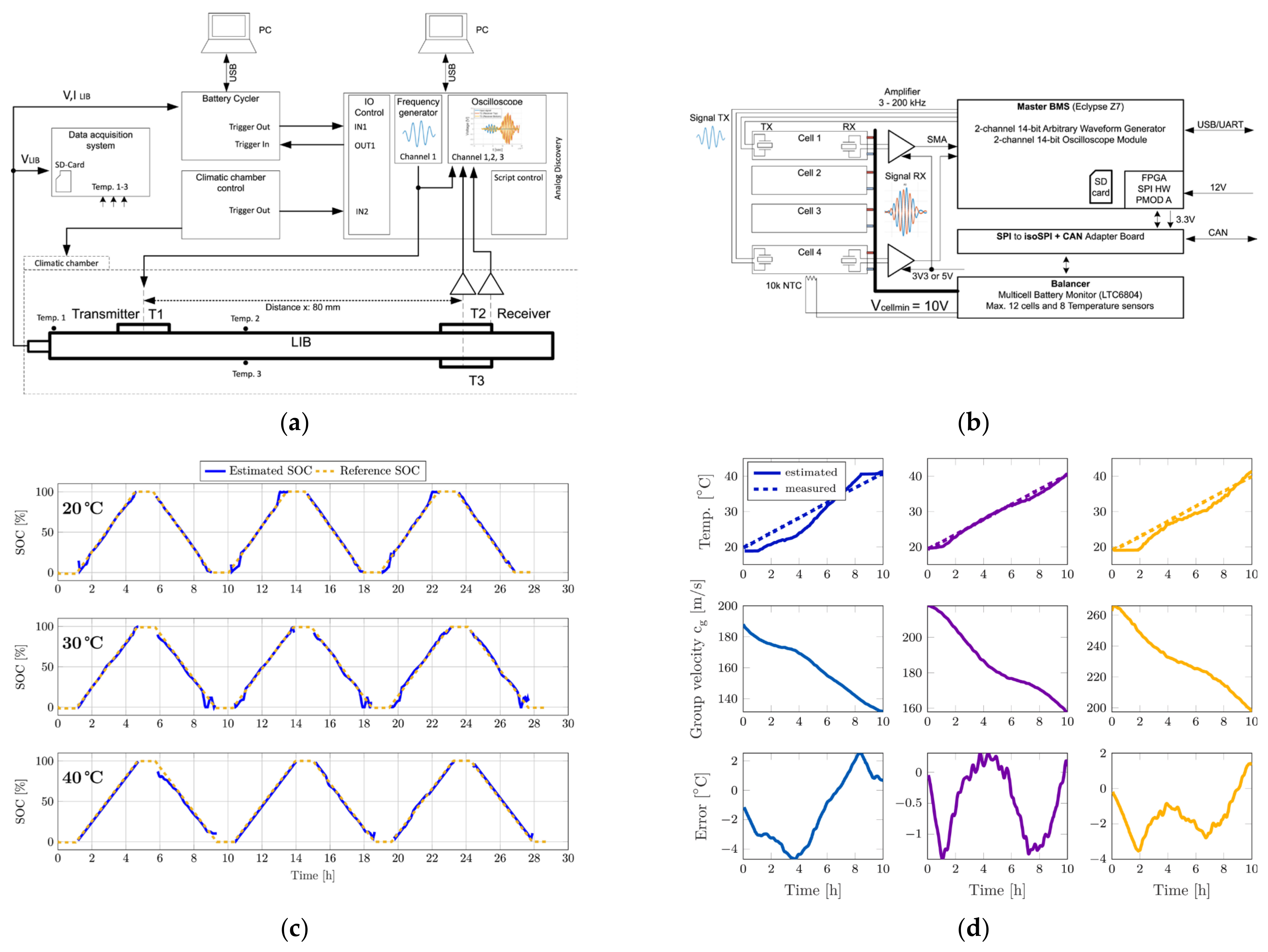
2.2. Ultrasonic Testing for the SOC and SOH of Lithium Batteries

Overcharging is a common fault in lithium-ion batteries. The Total Focusing Method (TFM) is an algorithm based on the full matrix capture that discretizes the imaging area into grids. By combining 2D/3D TFM and A-scan (amplitude scan), Shen [34] used reflection-wave-based ultrasonic testing technologies to detect abnormal behaviors of batteries under overcharging in situ. Figure 4 shows that the ultrasonic testing method can effectively perform non-destructive testing on pouch batteries [34]. Figure 4b indicates that the range of the amplitude of sound waves varies due to concentration polarization. Figure 4c captures the disappearance of the first echo and visualizes the evolution process of a large amount of gas. Li [17] used ultrasonic guided waves to conduct experiments on lithium-ion polymer batteries and diagnose the generation of side reaction gases under overcharging and over-discharging processes. Through cyclic aging experiments on lithium-ion batteries, Li [35] found that as the lithium-ion battery aged, the change in ultrasonic signals increased; the trend of characteristic parameter changes of SOC for the aged battery was opposite to that of the fresh battery. The result indicates that ultrasonic characteristic parameters are affected by battery aging, and ultrasonic guided waves can effectively perform non-destructive testing on battery aging. Zhao [36] proposed a method for evaluating the SOC and SOH of lithium-ion batteries using non-contact ultrasonic guided-wave detection technology with a multi-parameter analysis method. In battery aging experiments, the guided-wave parameters vary during cycling, thus inferring the mechanical properties of the aged battery.

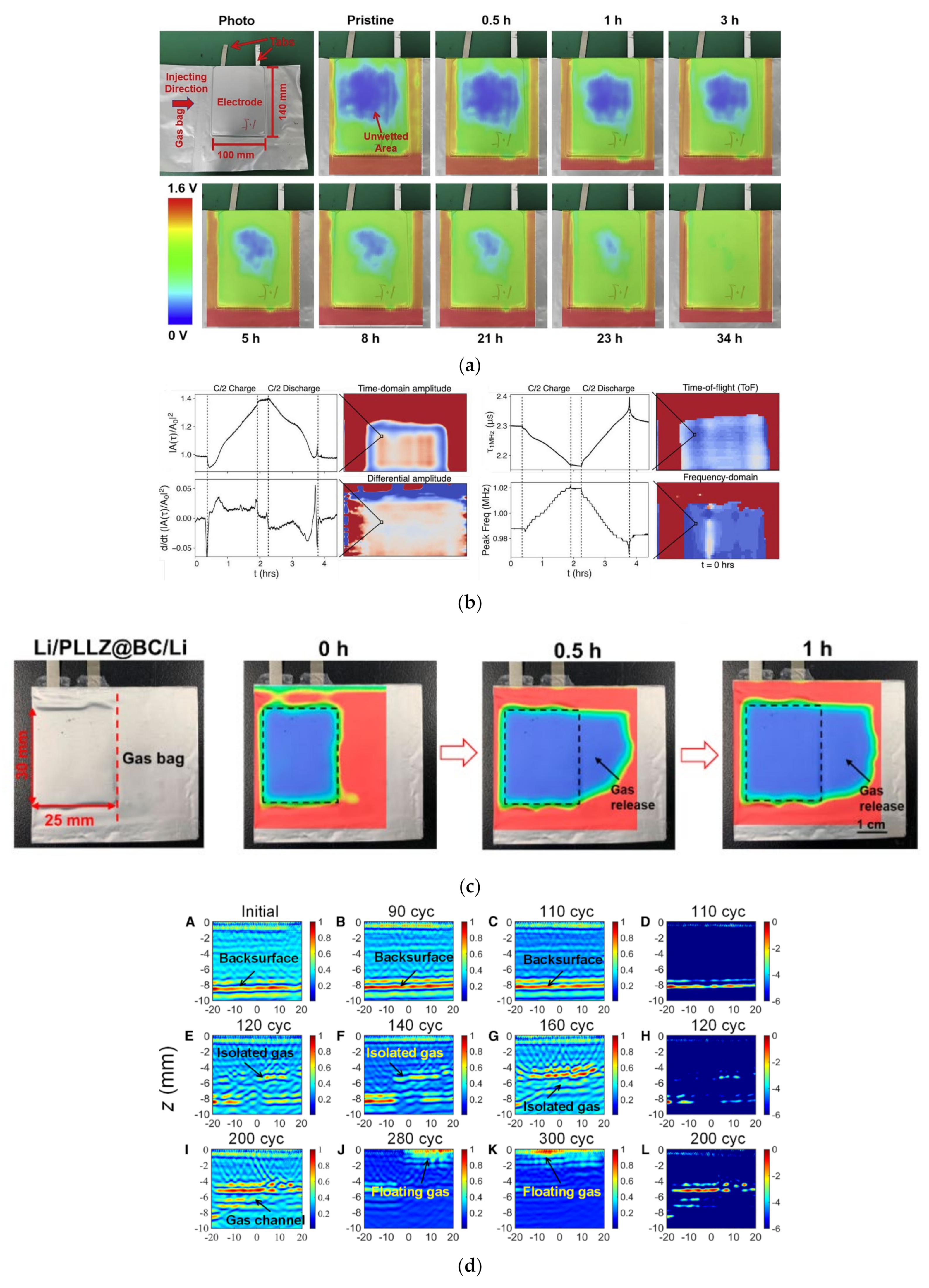
2.3. Ultrasonic Testing of Mechanical Defects in Lithium Batteries

For cylindrical lithium-ion batteries, Choi [8] developed a laser ultrasonic testing system for detecting weld defects. Figure 5a shows that a weld defect leads to the increased amplitude of the antisymmetric Lamb wave and the decreased effective bending stiffness of the welded component. In Figure 5b, James [37] found that defects such as cracks and dislocations in lithium-ion batteries could cause attenuation of resonance peak amplitude, showing an opportunity for precise localization of defect locations in cells. Huang [38] used ultrasound resonance to quantitatively characterize the layered structure inside lithium-ion batteries. These results indicate that the electrochemical reactions of the defective batteries can alter the key parameters, including the density, elastic constants, and thickness of the electrode film. These characteristics could affect ultrasonic resonance and could be detected through ultrasonic resonance. As shown in Figure 5c, Hwang [39] used non-destructive ultrasonic testing technology and deep learning techniques and experimentally obtained ultrasound signal databases to verify the resistance spot welding status between electrodes and cans. In Figure 5d, Cho [40] used the air-coupled ultrasonic non-destructive testing technique with Lamb waves to test the sealing integrity of lithium-ion batteries under a dry testing environment. By using TFM on an ultrasonic welding lithium-ion pouch battery, Bruder [41] found that guided waves produced by laser could be utilized to evaluate the defect, which is a significant reflector in the propagation plane.

2.4. Other Methods Based on Ultrasonic Testing of Lithium Batteries

Li [44] constructed a simplified finite element simulation model for the ultrasonic transmission characteristics of batteries. By comparing and analyzing the ultrasonic transmission characteristics of pristine batteries, batteries with inconsistent structures, and batteries with structural defects, the relationship between battery inconsistency conditions, fault conditions, and characteristic parameters was given [44]. In Figure 6a,b, Markus [45] developed a new ultrasonic battery management system (UBMS) that could track mechanical changes by using ultrasonic sensors. Their work demonstrates that the temperature and SOC of lithium-ion batteries could be estimated by the combination of piezoelectric transducers and Lamb waves. Figure 6c,d show that the differences between the experimental data and the estimated results are quite small. These sensors could also be used to detect battery expansion or even severe deformation of the battery. By studying local heating, Tyler [46] expanded the applicability of ultrasonic damage detection, and the results indicate that the sensor and heat source do not need to be in the same position to detect damage caused by thermal abuse.
Ultrasound imaging technology is also a method to visually display defects in lithium-ion batteries. Traditional imaging methods, such as X-ray CT methods, are not efficient in detecting the wetting quality. By using a focused ultrasonic beam, Deng [47] demonstrated that ultrasound transmission imaging could measure the electrolyte wetting quality and process, as shown in Figure 7a. Chang [48] described various acoustic modes used for lithium battery detection. Figure 7b depicts that the Time of Flight (a method to measure the distance by calculating the propagation time of waves) analysis could plot the propagation time of waves, relating the speed of sound to changes in the modulus and thickness, and could quantify unit expansion and stiffness changes [48]. Zheng [49] proposed an in situ imaging approach for thin lithium-ion pouch batteries using guided waves and found that the amplitude of waves within the irregular pattern, staying in the damage, is relatively higher.
The generation or loss of trace gases could also be reflected in ultrasonic images. Huo [50] evaluated the interface stability of solid-state pouch batteries in the gas-releasing state by ultrasound imaging. Figure 7c shows the time-dependent ultrasound image of a battery during trace gas release [50]. Xu [51] proposed an in situ underground ultrasound array imaging method for detecting, locating, and characterizing the gases generated inside lithium-ion batteries. Meanwhile, Xu [51] collected ultrasonic signals affected by internal gases using a full matrix capture method.

3. Computer Tomography of Lithium Batteries

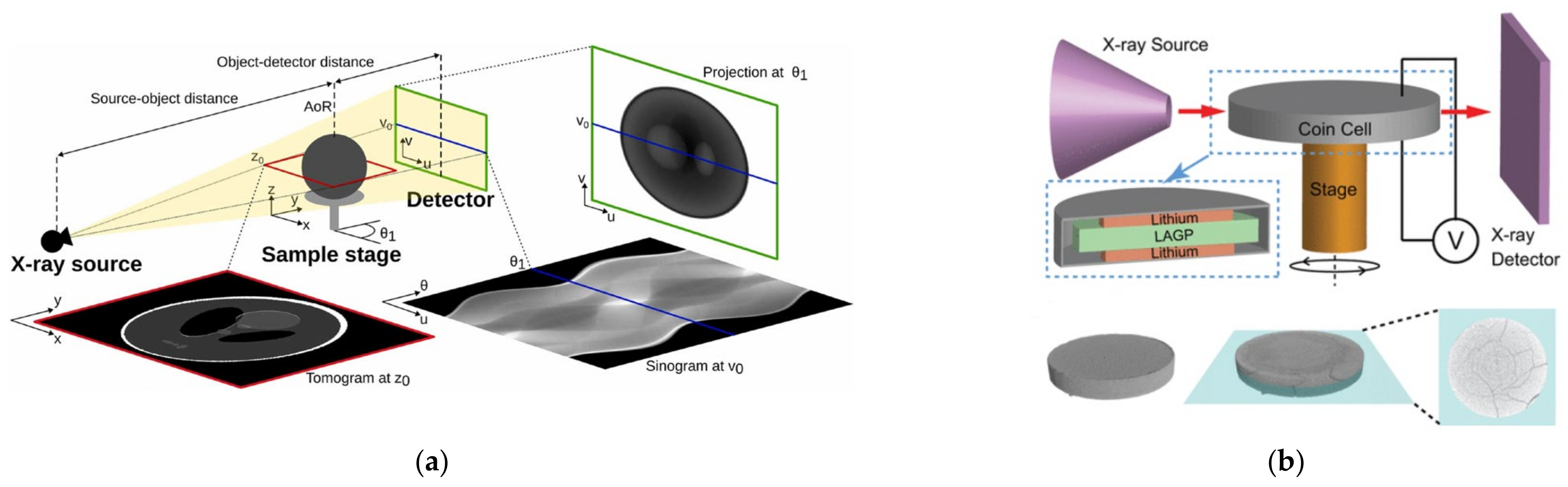
3.1. Principle of X-ray CT Detection for Lithium Batteries

Figure 8 illustrates the working principle of X-ray CT. Different phases and components in the tested sample have different atomic coefficients and densities that show weak or strong absorption of X-rays, which causes differences in imaging brightness [52]. There are two main X-ray CT techniques in lithium batteries: 2D X-ray projection imaging and 3D X-ray computed tomography [53,54]. X-ray computed tomography has micrometer imaging and nanometer imaging. Micrometer imaging is mainly used to capture structural changes in lithium batteries, such as cracks or damage, while nanometer imaging is mainly used for ex situ measurements, such as particle cracking [53]. For the limitations of micrometer and nanometer resolutions in experiments, a combination of X-ray microscopes (XRMs) and X-ray CT can be used. The X-ray microscope is responsible for geometric optical amplification, while X-ray CT is responsible for reconstructing and generating three-dimensional images [55]. Figure 9 displays X-ray CT imaging at both the microscale and nanoscale levels [55].

3.2. X-ray CT Detection of Overcharging and Over-Discharging of Lithium Batteries

X-ray CT can effectively detect defects caused by overcharging and over-discharging of lithium-ion batteries. Finegan [57] combined a comprehensive method of high-speed X-ray CT and thermal imaging to study the effects of heating and gas generation on battery structure during failure, and Figure 10 shows the electrode film delamination, gas formation, and consequent battery swelling. Zhang [18] studied the influences of heating and gas production on the internal structure of overcharged batteries using X-ray CT. As the SOC increases during overcharge, gas production leads to more pronounced deformation of the battery, electrode separation, and bending [18]. For overcharged batteries, the gas production would increase exponentially. Meanwhile, Zhang [19] also studied the effect of over-discharge on battery behaviors. Over-discharge can cause gas generation and copper dissolution. During the over-discharge process, the temperature rapidly rises to its peak and then decreases. By using X-CT on lithium iron phosphate batteries, Carter [43] indicated that some batteries would have plated lithium due to overcharging, while others would produce copper deposits due to over-discharging. Figure 10b shows the multiscale analysis of damage after over-discharging [43].

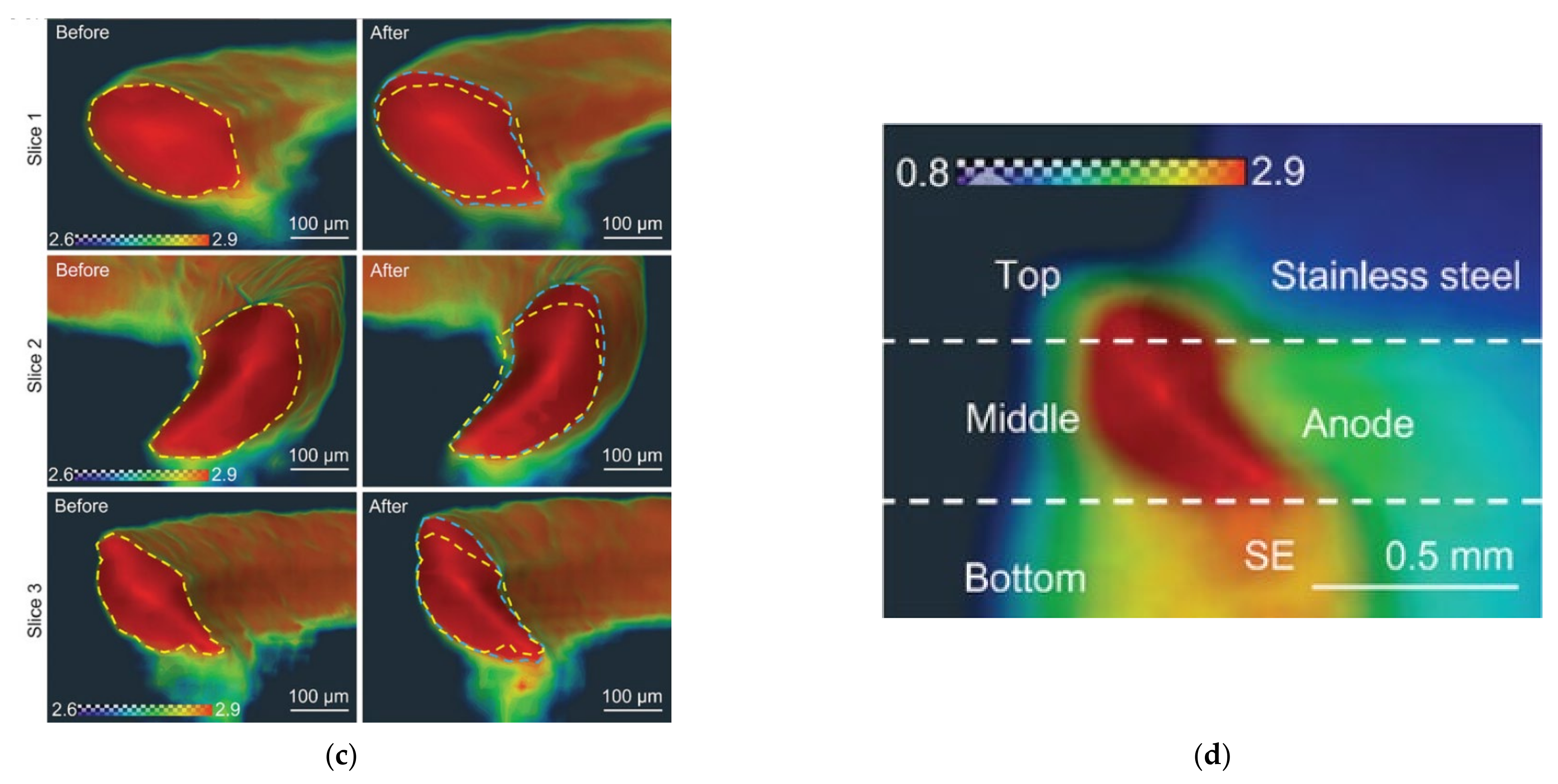
3.3. X-ray CT Detection of Mechanical Damage in Lithium Batteries

Advanced instruments and new strategies are required to explore the mechanical failure of batteries, which is a complex accumulation process. X-ray CT provides an effective approach for failure analysis. Chen [58] used 2D/3D X-ray CT to study the failure mechanisms of battery packs at low temperatures. Lithium-ion batteries exhibit swelling at high charge and discharge current densities due to the deformation of electrodes, formation of lithium dendrites, and active material expansion. At this point, the electrochemical kinetics of graphite anodes is slow, and the lithium dendrite formation could lead to catastrophic short circuits. Hao [59] successfully distinguished and separated the lithium dendrite morphology in garnet-based solid electrolytes by using X-ray nano-CT, and the results indicate that physical properties and the electrochemical driving force of solid electrolytes show a comprehensive impact on crack formation and lithium dendrite growth. The combination of delayed X-ray CT and digital volume correlation (a tool for obtaining the internal kinematic field of materials by imaging) has been proven to be an effective diagnostic technique. Finegan [60] used X-CT and digital volume correlation to track the progress of lithiation by measuring local displacements of electrodes, providing insights into the transient structural mechanics during the operation of commercial batteries. The displacements of current collectors and battery materials can lead to crack formation and electrode film detachment during discharging. The basic principle of X-ray diffraction (XRD) is that X-rays scattered by different atoms interfere with each other, producing a strong diffraction pattern in certain directions. The diffraction pattern produced by each crystal reflects the atomic distribution characteristics inside the crystal. Wade [61] used ex situ XRD and X-ray CT to perform post-mortem analysis on electrodes in the delithiated state after first charging. Figure 11a,b revealed the formation of cracking that occurred during early operations; as the voltage raised during delithiation, cracks in all electrodes would also increase [61].
For traditional non-destructive testing methods and disassembly-based destructive analysis, it is difficult to detect capacity degradation and explosion hazards in lithium-ion batteries. In contrast, X-ray CT is a spatial, non-destructive method that does not change the battery structure. It can quantify material properties and detect internal structural features of batteries, thereby helping to identify potential faults [62]. Ziegler [63] conducted a battery aging experiment where a thermal event occurred and security systems in the cell had been destroyed, showing various damage (Figure 11c). This clearly indicates the impact of the explosion on cells. For multiple series and parallel batteries, the risk of fire significantly increases. In addition to the safety mechanism inside the batteries, we need to constantly maintain non-destructive testing of the status of health in lithium batteries.
For solid-state lithium batteries, the interface changes between lithium metal electrodes and solid-state electrolytes (SSEs) could cause increased impedance and decreased capacity during charging/discharging processes. Jared [56] used in situ X-ray CT to study the mechanical damage evolution inside SSEs induced by the interphase growth during electrochemical cycling. The interphase growth leads to the fracture of the material, and the fracture dominates the increase in impedance rather than the resistance of the interface itself. The segmented data in Figure 11d could quantify the crack volume and number of cracks within the SSE particles during the cycling process [56].
Figure 11. X-ray CT imaging of mechanical defects in lithium batteries. (a) X-ray CT of electrode particle cracks [61]. (b) A 3D volume rendering of electrode degradation based on X-CT [61]. (c) X-ray CT scan of the deformations caused by the thermal event [63]. © 2020 by the authors. Licensee MDPI, Basel, Switzerland. (d) The crack volume and number of cracks within the LAGP particles [56]. Copyright © 2019, American Chemical Society.
Energies 17 04030 g011aEnergies 17 04030 g011b

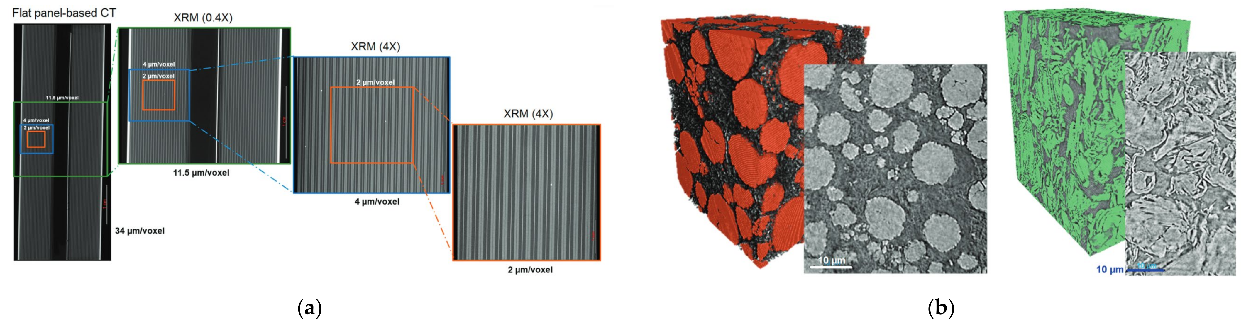
3.4. Application of X-ray CT in Commercial Lithium Batteries

The 18650 lithium-ion battery is a standardized model developed by SONY Corporation in Japan. The diameter and length of the 18650 battery are 18 mm and 65 mm, respectively, and 0 means the battery is cylindrical. By using computed tomography imaging and post-mortem analysis, features related to commercial 18650 cells can be identified [64]. Table 3 shows some examples of using X-ray CT to detect commercial batteries. Heenan [65] obtained the structure and electrochemical data of 18650 lithium-ion batteries from the cell scale to the particle scale using X-ray computed tomography. Pfrang [64] used micro X-ray CT and found that the jelly roll exhibited significant deformation after charging–discharging cycles. During the charging process, cracking may occur at different scales in commercial lithium batteries. Diao [66] used X-ray CT to monitor the electrical, thermal, and mechanical behaviors of cells. X-ray CT can be combined with other methods to develop new detection methods. Combining X-ray CT with XRD can capture various chemical heterogeneity in batteries [67]. Except for the large defects of electrode breakage caused by overcharging in lithium-ion batteries, the internal short circuits of the 18650 cells caused by slight overcharging could also be detected using X-ray CT [68].

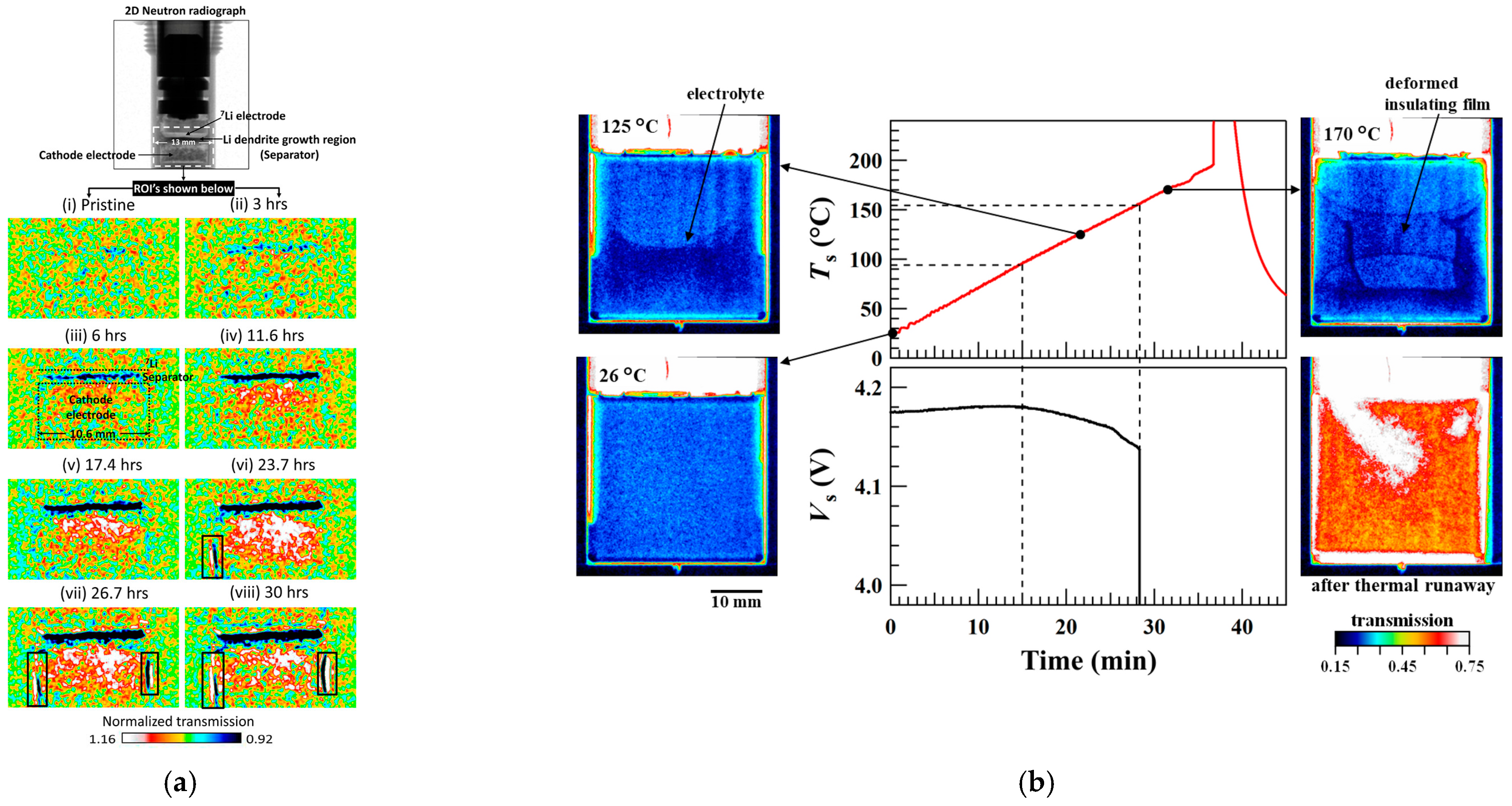
3.5. Neutron Tomography for Lithium Battery

X-rays could not distinguish lithium metal from voids and cracks. In contrast, neutron imaging can visualize light elements, and thus, it can be used to distinguish Li from voids, overcoming the limitations of X-ray imaging [69]. For extreme fast charging, dead lithium on the anode is one of the critical failure mechanisms. Maha [70] proved the feasibility of in situ observation of dead lithium on the graphite anode using high-resolution neutron microscopy computed tomography. Song [71] applied neutron imaging to study the growth of lithium dendrites and the dynamic distribution of Li from the anode to the cathode during the charging process, and Figure 12a shows the time-resolved in situ neutron radiography, which could display dendrite growth and lithium distribution. Nozaki [72] observed the structural deformation of LIBs during the heating process using the in situ neutron imaging method, and Figure 12b shows the in situ neutron imaging system, which can obtain the internal structural deformations of batteries at a time resolution of a few seconds.
As the most common fault in all-solid-state Li metal batteries (ASLMB), short circuit is divided into “hard short” and “soft short”. For the hard short, the voltage will sharply decrease during charging, and the battery cannot be restored, which is the most common short circuit. In contrast, the phenomenon of “soft short” is often observed in ASLMB, but it has not yet been well understood. Cao [73] successfully visualized Li behavior in ASLMB by combining neutron and X-ray imaging, and Figure 12c shows dashed lines underlining the contours of the lithium cross-section before and after testing, respectively. After the electrochemical testing, the cross-sectional area of lithium seemed to increase, but the contour of lithium did not simply expand. The lithium content in the upper area increased, and a similar phenomenon could also be observed in the bottom area of lithium. On the contrary, the contraction of lithium in the center region indicates a reduction in lithium content [73].

4. Lithium Battery Non-Destructive Test Using Magnetic Resonance Detection

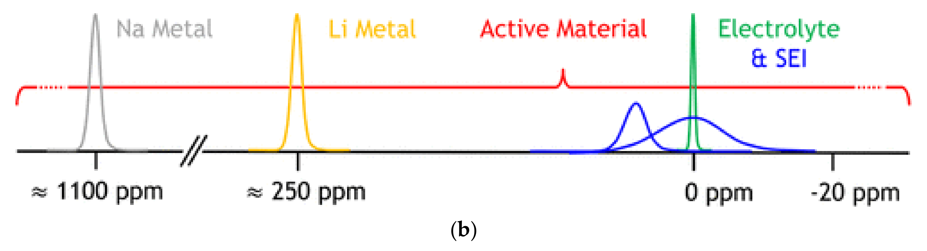
4.1. Principle of Nuclear Magnetic Resonance Detection for Lithium Batteries

Nuclear magnetic resonance (NMR) is sensitive to the spin-bearing atom environment, and the entire sample contributes to the signal [74]. Oliver [75] explained the principle of NMR detection for lithium-ion batteries. The chemical and electrochemical processes rely on the redox reaction, and lithium ions usually directly participate in the reactions and generate the lithium NMR spectra [75]. Figure 13b covers a vast frequency range closely related to the studied material, and the NMR signal of active materials (red) is affected by chemical, Knight, and Fermi contact shifts [75].
Two differences between nuclear magnetic resonance and other methods are the inherent length and time scale of the performed measurements. When the nucleus is exposed to different environments, the molecular movement of the nucleus may result in larger length scales. The chemical transformation during delayed in situ experiments is a direct measurement of the time scale of NMR spectra [76].
Except for liquid electrolytes, most components inside secondary batteries are solid. Solid-state nuclear magnetic resonance is a supplement to long-range diffraction methods and a powerful tool for detecting localized atomic/ion environments in crystalline and amorphous materials [77]. There are two main applications of nuclear magnetic resonance in lithium batteries: in situ NMR and ex situ NMR.

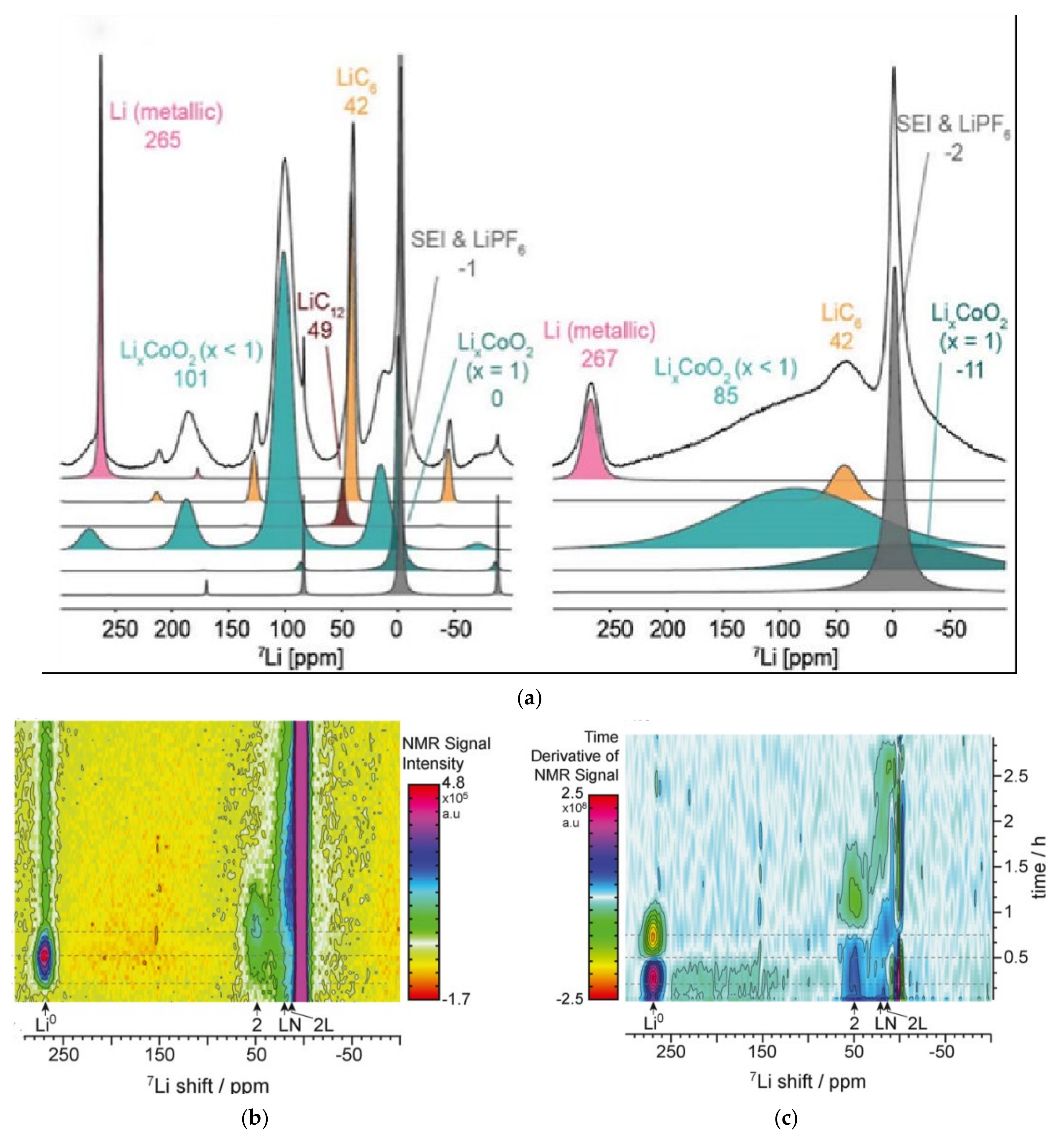
4.2. In Situ Nuclear Magnetic Resonance

In situ nuclear NMR can detect the morphology and electroplating behavior of lithium metals and obtain quantitative results of lithium deposition [78]. Anna [78] utilized in situ NMR technology to study the effects of ethylene fluoroethylene carbonate (FEC) on the lithium electrodeposition and the solid electrolyte interphase (SEI) on the lithium anode. The results show that FEC could accelerate the formation of SEI. If the SEI film was broken, the freshly exposed lithium would be passivated faster.
The mechanism of lithium metal plating on the anode during overcharge is very important for managing battery safety. Freytag [79] used a new in situ magic-angle spinning 7Li NMR (a method to determine the structure for the ordered system without translation symmetry) method, and Figure 14a shows a slight decrease in chemical shift and intensity. Such a small chemical shift change (approximately 2 ppm) is unsolvable in static in situ experiments. By using in situ NMR, Gotoh [80] observed the overcharge state of graphite and hard carbon electrodes in LIB. Li NMR signal intensity of quasi-metallic lithium did not decrease after the initiation of dendritic formation, indicating that most quasi-metallic lithium did not participate in the lithium dendrite nucleation.
Lithium plating causes safety issues through dendritic growth and damages the fast-charging ability of the battery [81]. In the NMR spectrum from Figure 14b,c, Kevin [81] pointed out that the peak at 270 ppm was attributed to lithium, and the rate of lithium metal embedded in graphite was inversely proportional to the dead lithium amount. Dead lithium would reduce the amount of electrically active lithium in the battery and reduce the kinetics of the reaction of lithium embedded in graphite [81].

4.3. Ex Situ Nuclear Magnetic Resonance

Ex situ NMR is an important technique for non-destructive testing of lithium-ion batteries. One of the key degradation mechanisms in lithium-ion batteries is the irreversible loss of recyclable lithium during cycling. Fang [82] used ex situ NMR to measure the aged samples of commercial batteries and to quantify dead lithium and SEI, further revealing the lithium dendrite entrained in the separator after battery disassembly. From the NMR spectra in Figure 15a, it can be seen that “Fresh battery” shows only lithium ions. “Aged-I” shows plated lithium, and “Aged-II” has more plated lithium, which indicates that the irreversibility and aging of the battery are more serious. Xie [83] studied the non-uniform degradation caused by lithium plating and performed magic-angle spinning (MAC)-NMR detection of different SOC and SOH under 2C at 10 °C. In Figure 15b, there is no lithium signal at 100% SOH. With the decrease in SOH, the signal increases gradually. For the anode with 50% SOH, a strong peak of 268.5 ppm is observed in the three regions, indicating that lithium plating even occurs in the battery center. Thus, lithium plating is a critical aging mechanism of batteries. Zheng [42] analyzed the interface dynamics of Li10SnP2S12/Li metal by MAC-NMR and revealed that the rough and porous interface leads to an increase in resistance and dendrite formation at the Li10SnP2S12/Li interface. Figure 15c indicates that the deterioration of the previously dense solid/solid contact causes the loss of interface contact and the reduction in lithium-ion conductive channels, which seriously hinders the ion transport at the Li10SnP2S12/lithium interface [42].
Magnetic resonance imaging (MRI) can monitor the overall mass transfer in electrolyte and the effect of electrochemical deposition/dissolution related to SEI formation. Xie [84] revealed the effect of electrolyte additives on the lithium metal battery through solid-state NMR/MRI analysis. One-dimensional MRI technology based on spatial resolution can conveniently monitor the local concentration distribution of ions in electrolyte. The MRI curve in Figure 16a shows that the consumption of anions in electrolyte is different from that in the reference electrolyte during continuous lithium deposition. The intensity distribution shows that the anion consumption intensity on the cathode side is low.
Surface-scan MRI, as a non-destructive method, is used for the diagnosis of lithium batteries. Romanenko [85] used ultrafast surface-scan MRI to observe the memory effect related to the degradation of rechargeable lithium-ion batteries. Local degradation of the electrode and electrolyte can be manifested as strong sporadic direct current (DC) field changes limited to the region of a few MRI pixels. Figure 16b shows strong deviation between the two fields in the dotted circles, indicating the overcharging of the battery, and these changes may be related to battery failure caused by overcharging, such as cathode deterioration, electrolyte oxidation, and dendrite formation [85].

4.4. Other Methods of Nuclear Magnetic Resonance

In addition to in situ and ex situ NMR and MRI, there are many other methods of non-destructive testing for lithium-ion batteries. Here is a brief introduction to the recent applications of other methods of nuclear magnetic resonance.
Dynamic nuclear polarization is a branch of nuclear magnetic resonance spectroscopy that utilizes microwaves to excite free electron transitions, resulting in polarization of the spin energy level distribution of the relevant nuclei. Dynamic nuclear polarization nuclear magnetic resonance can typically increase the detection sensitivity of nuclear magnetic resonance signals by several orders of magnitude. Zhang [86] indicated that dynamic nuclear polarization can selectively enhance the 7Li NMR signal of lithium deposited on the electrodes. Low field 7Li dynamic nuclear polarization spectroscopy is a useful tool for studying lithium deposition on the electrode surface during charging/discharging.
Variable-temperature operando solid-state NMR is a nuclear magnetic resonance technique used to study the molecular structure and interactions of substances at different temperatures. Variable-temperature operando solid-state NMR can reveal the effect of temperature on the microstructure evolution of lithium metal in carbonate-based electrolyte systems. Tao [87] found that the microstructure of lithium exhibits similar evolution patterns at low/normal temperatures, and the poor morphology resulted in a large amount of inactive lithium. However, large and dense lithium deposits are formed at high temperatures, and less dead lithium is detected. The intensification of electrolyte consumption during SEI formation accounts for the capacity loss.
T1 NMR relaxation is used to determine the interactions and dynamic processes between the nuclear spin system and its surrounding environment. Schleker [88] revealed the equilibrium of lithium ions at the solid electrolyte interface through T1 NMR relaxation, and the results have demonstrated the equilibrium of non-faradaic lithium exchange at the interface between liquid electrolytes and solid ceramic electrodes. The research provided a foundation for quantitative defect engineering and could be used to improve the rate capability of batteries.

5. Summary

Lithium batteries are extensively used in electric vehicles and electronic devices due to their long cycle life and high capacity. The safety of batteries has put forward higher requirements for the use of lithium batteries. One of the strategies for distinguishing whether lithium batteries are in a safe state is to conduct NDT on the batteries.
The UT of lithium batteries is usually carried out using reflected or transmitted waves with different amplitudes or frequencies generated by ultrasonic waves at battery defects. One of the advantages of UT compared to other NDT techniques is the fast detection speed, which could quickly determine whether there are defects in the battery. Ultrasonic sensors could track the mechanical changes of the battery for real-time monitoring. With the development of ultrasound imaging technologies such as TFM, ultrasound imaging could effectively measure battery wetting quality that could not be accurately identified by other imaging methods. The problem with UT is that it mostly tests a single sample, and the cost and scale issues limit the extensive application of UT for lithium batteries in the industry.
The CT principle is based on the difference in imaging brightness caused by the difference in the absorption strength of radiation between the defective area and the intact area in batteries. The advantage of X-ray CT is that CT can perform both 2D and 3D imaging, intuitively displaying the location and type of battery defects. Meanwhile, due to the development of technology, X-ray CT has been able to identify nanoscale defects such as electrode particle cracks. X-rays cannot accurately distinguish between voids in electrodes and lithium metals, while neutrons can be accurately identified due to their sensitivity to atomic nuclei. The combination of X-ray CT and neutron tomography is an important method for CT imaging of defects in lithium batteries. Because of radiation issues, CT detection poses certain risks. Therefore, it is necessary to develop new CT technology or consider protective clothing and isolation compartments to reduce radioactive pollution.
The principle of NMR is that lithium ions participate in the oxidation–reduction reaction in the electrochemical process and generate corresponding NMR spectra. NMR has a large inherent length and time scale. NMR is a practical tool for detecting the local atomic or ionic environment in batteries. In situ NMR and ex situ NMR can detect the morphology and electroplating behavior of metallic lithium, as well as provide quantitative and temporal information on the deposition of metallic lithium. MRI can monitor the overall mass transfer process of electrolytes and the impact of electrochemical deposition. MRI has almost no radiation compared to CT and can directly image without the need for 3D modeling and reconstruction. However, the examination time for MRI is longer, and the image is less clear. Improving detection efficiency and enhancing image resolution are the future development directions of NMR technology.
Nevertheless, these three NDT methods for lithium batteries still face some challenges:
(i)
Could NDT techniques for some new electrode materials of lithium batteries (such as graphene, carbon silicon composite materials, etc.) also provide accurate detection?
(ii)
Could we obtain more accurate predictions about the health status and lifespan of lithium batteries, as well as effective warnings before battery failures occur?
(iii)
CT technology can already be precise to the microscale and nanoscale defects in lithium batteries. However, could ultrasound microscopy technology be applied to the detection of microscale defects in lithium batteries?
Combining multiple non-destructive tests has more potential than using a single method. For future development, NDT methods should move towards a faster, more cost-effective, and more accurate direction. By combining algorithms such as machine learning, NDT could develop more applications for monitoring the health status of lithium batteries. With the development of NDT theory and practical applications, the safety of lithium batteries is bound to be further improved.

Author Contributions

Conceptualization, F.H.; methodology, S.W.; validation, J.G. and S.W.; formal analysis, J.G.; investigation, J.G. and S.W.; writing—original draft preparation, J.G. and S.W.; writing—review and editing, J.G. and S.W.; supervision, F.H. All authors have read and agreed to the published version of the manuscript.

Funding

This research was funded by the Guangdong Basic and Applied Basic Research Foundation (Grant No. 2022A1515010950).

Data Availability Statement

The data presented in this study are available in the article.

Conflicts of Interest

The authors declare no conflicts of interest.

References

  1. Zhang, M.; Liu, Y.; Li, D.; Cui, X.; Wang, L.; Li, L.; Wang, K. Electrochemical Impedance Spectroscopy: A New Chapter in the Fast and Accurate Estimation of the State of Health for Lithium-Ion Batteries. Energies 2023, 16, 1599. [Google Scholar] [CrossRef]
  2. Owen, R.E.; Robinson, J.B.; Weaving, J.S.; Pham, M.T.M.; Tranter, T.G.; Neville, T.P.; Billson, D.; Braglia, M.; Stocker, R.; Tidblad, A.A.; et al. Operando Ultrasonic Monitoring of Lithium-Ion Battery Temperature and Behaviour at Different Cycling Rates and under Drive Cycle Conditions. J. Electrochem. Soc. 2022, 169, 040563. [Google Scholar] [CrossRef]
  3. Rahman, A.; Lin, X.; Wang, C. Li-Ion Battery Anode State of Charge Estimation and Degradation Monitoring Using Battery Casing via Unknown Input Observer. Energies 2022, 15, 5662. [Google Scholar] [CrossRef]
  4. Zou, B.; Zhang, L.; Xue, X.; Tan, R.; Jiang, P.; Ma, B.; Song, Z.; Hua, W. A Review on the Fault and Defect Diagnosis of Lithium-Ion Battery for Electric Vehicles. Energies 2023, 16, 5507. [Google Scholar] [CrossRef]
  5. Chen, Y.; Kang, Y.; Zhao, Y.; Wang, L.; Liu, J.; Li, Y.; Liang, Z.; He, X.; Li, X.; Tavajohi, N.; et al. A review of lithium-ion battery safety concerns: The issues, strategies, and testing standards. J. Energy Chem. 2021, 59, 83–99. [Google Scholar] [CrossRef]
  6. Liu, J.; Wang, Z.; Bai, J. Influences of multi factors on thermal runaway induced by overcharging of lithium-ion battery. J. Energy Chem. 2022, 70, 531–541. [Google Scholar] [CrossRef]
  7. Wang, Z.; Zhao, X.; Fu, L.; Zhen, D.; Gu, F.; Ball, A.D. A review on rapid state of health estimation of lithium-ion batteries in electric vehicles. Sustain. Energy Technol. Assess. 2023, 60, 103457. [Google Scholar] [CrossRef]
  8. Choi, S.; Liu, P.; Yi, K.; Sampath, S.; Sohn, H. Noncontact laser ultrasonic inspection of weld defect in lithium-ion battery cap. J. Energy Storage 2023, 73, 108838. [Google Scholar] [CrossRef]
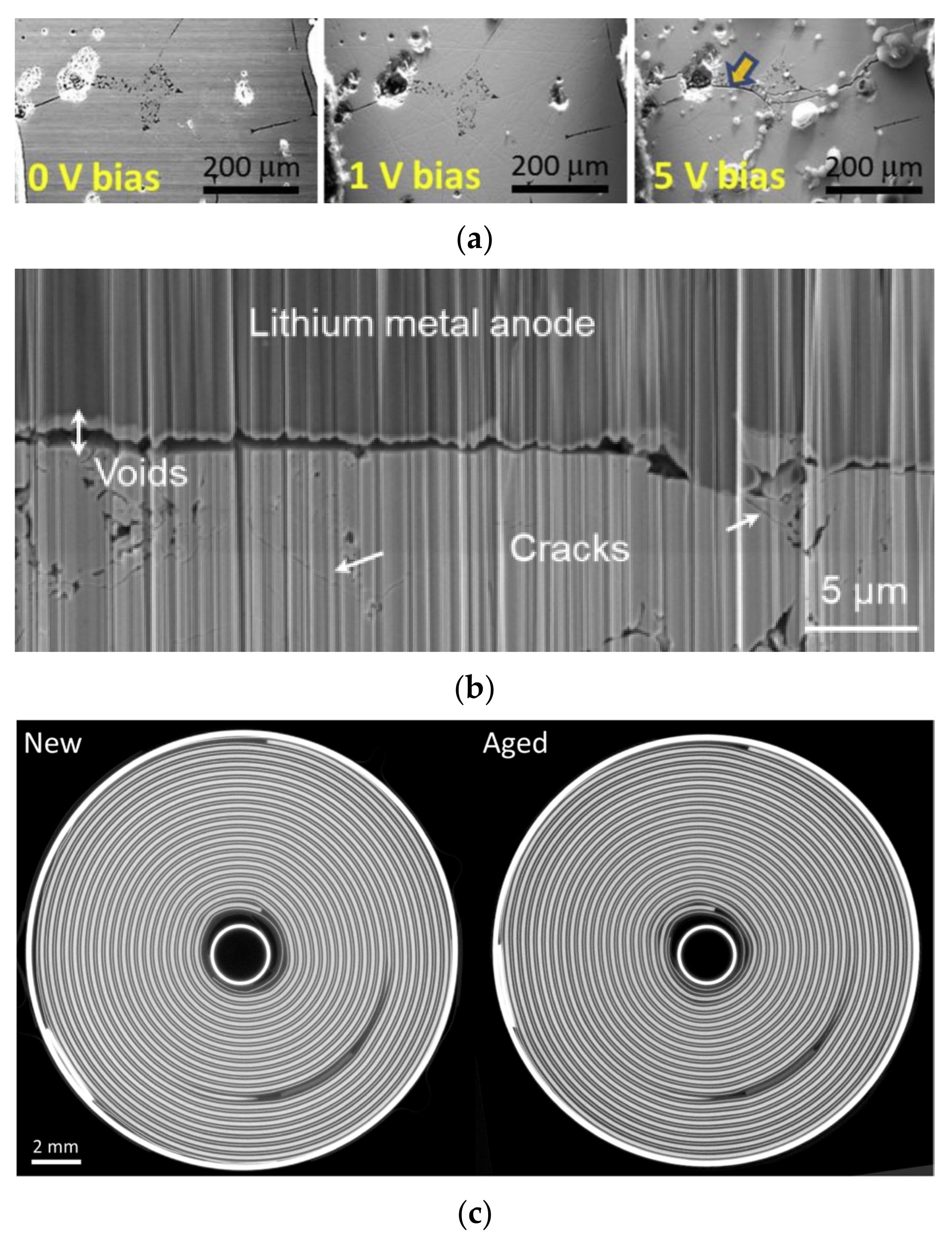
  9. Manalastas, W.; Rikarte, J.; Chater, R.J.; Brugge, R.; Aguadero, A.; Buannic, L.; Llordés, A.; Aguesse, F.; Kilner, J. Mechanical failure of garnet electrolytes during Li electrodeposition observed by in-operando microscopy. J. Power Sources 2019, 412, 287–293. [Google Scholar] [CrossRef]
  10. Duan, J.; Fuchs, T.; Mogwitz, B.; Minnmann, P.; Zuo, T.-T.; Henss, A.; Janek, J. Solid electrolyte cracking due to lithium filament growth and concept of mechanical reinforcement—An operando study. Mater. Today 2023, 70, 33–43. [Google Scholar] [CrossRef]
  11. Blazek, P.; Westenberger, P.; Erker, S.; Brinek, A.; Zikmund, T.; Rettenwander, D.; Wagner, N.P.; Keckes, J.; Kaiser, J.; Kazda, T.; et al. Axially and radially inhomogeneous swelling in commercial 18650 Li-ion battery cells. J. Energy Storage 2022, 52, 104563. [Google Scholar] [CrossRef]
  12. Chacón, X.C.; Laureti, S.; Ricci, M.; Cappuccino, G. A Review of Non-Destructive Techniques for Lithium-Ion Battery Performance Analysis. World Electr. Veh. J. 2023, 14, 305. [Google Scholar] [CrossRef]
  13. Wang, Y.; Lai, X.; Chen, Q.; Han, X.; Lu, L.; Ouyang, M.; Zheng, Y. Progress and challenges in ultrasonic technology for state estimation and defect detection of lithium-ion batteries. Energy Storage Mater. 2024, 69, 103430. [Google Scholar] [CrossRef]
  14. Gao, J.; Zhang, L.; Lyu, Y.; Shi, F.; Wu, B.; He, C. Ultrasonic guided wave measurement and modeling analysis of the state of charge for lithium-ion battery. J. Energy Storage 2023, 72, 108384. [Google Scholar] [CrossRef]
  15. Cai, Z.; Pan, T.; Jiang, H.; Li, Z.; Wang, Y. State-of-charge estimation of lithium-ion batteries based on ultrasonic detection. J. Energy Storage 2023, 65, 107264. [Google Scholar] [CrossRef]
  16. Li, H.; Zhou, Z. Numerical Simulation and Experimental Study of Fluid-Solid Coupling-Based Air-Coupled Ultrasonic Detection of Stomata Defect of Lithium-Ion Battery. Sensors 2019, 19, 2391. [Google Scholar] [CrossRef]
  17. Li, X.; Hua, W.; Wu, C.; Zheng, S.; Tian, Y.; Tian, J. State estimation of a lithium-ion battery based on multi-feature indicators of ultrasonic guided waves. J. Energy Storage 2022, 56, 106113. [Google Scholar] [CrossRef]
  18. Zhang, X.; Li, L.; Xu, W. Analysis of Gas Production in Overcharged Lithium Battery by X-Ray Computed Tomography. J. Electrochem. Energy Convers. Storage 2020, 18, 021013. [Google Scholar] [CrossRef]
  19. Zhang, X.; Li, L.; Li, S. Research on Overdischarge Lithium-Ion Battery Based on X-Ray Computed Tomography. J. Electrochem. Energy Convers. Storage 2022, 20, 041004. [Google Scholar] [CrossRef]
  20. Hao, S.; Daemi, S.R.; Heenan, T.M.M.; Du, W.; Tan, C.; Storm, M.; Rau, C.; Brett, D.J.L.; Shearing, P.R. Tracking lithium penetration in solid electrolytes in 3D by in-situ synchrotron X-ray computed tomography. Nano Energy 2021, 82, 105744. [Google Scholar] [CrossRef]
  21. Ziesche, R.F.; Kardjilov, N.; Kockelmann, W.; Brett, D.J.L.; Shearing, P.R. Neutron imaging of lithium batteries. Joule 2022, 6, 35–52. [Google Scholar] [CrossRef]
  22. Haworth, A.R.; Cook, C.W.; Griffin, J.M. Solid-state NMR studies of coatings and interfaces in batteries. Curr. Opin. Colloid Interface Sci. 2022, 62, 101638. [Google Scholar] [CrossRef]
  23. Li, H.; Guo, S.; Zhou, H. In-situ/operando characterization techniques in lithium-ion batteries and beyond. J. Energy Chem. 2021, 59, 191–211. [Google Scholar] [CrossRef]
  24. Volkov, V.I.; Yarmolenko, O.V.; Chernyak, A.V.; Slesarenko, N.A.; Avilova, I.A.; Baymuratova, G.R.; Yudina, A.V. Polymer Electrolytes for Lithium-Ion Batteries Studied by NMR Techniques. Membranes 2022, 12, 416. [Google Scholar] [CrossRef] [PubMed]
  25. Zhang, B.; Lyu, Y.; Gao, J.; Song, G.; Lee, Y.-C.; He, C.; Song, W.; Chen, H. Ultrasonic reflection/transmission characteristics for state of charge of li-ion battery. Appl. Acoust. 2023, 214, 109687. [Google Scholar] [CrossRef]
  26. Song, G.; Li, Y.; Lyu, Y.; Chen, H.; Song, W.; Gao, J.; He, C. Ultrasonic reflection characteristics of Lithium-ion battery based on Legendre orthogonal polynomial method. Ultrasonics 2022, 124, 106736. [Google Scholar] [CrossRef] [PubMed]
  27. Sun, B.; Zhang, C.; Xu, Z.; Liu, S.; Yang, Q. Ultrasonic diagnosis of the nonlinear aging characteristics of lithium-ion battery under high-rate discharge conditions. J. Power Sources 2023, 567, 232921. [Google Scholar] [CrossRef]
  28. Wei, Y.; Yan, Y.; Zhang, C.; Meng, K.; Xu, C. State estimation of lithium-ion batteries based on the initial rise time feature of ultrasonic signals. J. Power Sources 2023, 581, 233497. [Google Scholar] [CrossRef]
  29. Meng, K.; Chen, X.; Zhang, W.; Chang, W.; Xu, J. A robust ultrasonic characterization methodology for lithium-ion batteries on frequency-domain damping analysis. J. Power Sources 2022, 547, 232003. [Google Scholar] [CrossRef]
  30. Sun, H.; Muralidharan, N.; Amin, R.; Rathod, V.; Ramuhalli, P.; Belharouak, I. Ultrasonic nondestructive diagnosis of lithium-ion batteries with multiple frequencies. J. Power Sources 2022, 549, 232091. [Google Scholar] [CrossRef]
  31. Sood, B.; Osterman, M.; Pecht, M. Health monitoring of lithium-ion batteries. In Proceedings of the 2013 IEEE Symposium on Product Compliance Engineering (ISPCE), Austin, TX, USA, 7–9 October 2013; pp. 1–6. [Google Scholar]
  32. Hsieh, A.G.; Bhadra, S.; Hertzberg, B.J.; Gjeltema, P.J.; Goy, A.; Fleischer, J.W.; Steingart, D.A. Electrochemical-acoustic time of flight: In operando correlation of physical dynamics with battery charge and health. Energy Environ. Sci. 2015, 8, 1569–1577. [Google Scholar] [CrossRef]
  33. Gold, L.; Bach, T.; Virsik, W.; Schmitt, A.; Müller, J.; Staab, T.E.M.; Sextl, G. Probing lithium-ion batteries’ state-of-charge using ultrasonic transmission—Concept and laboratory testing. J. Power Sources 2017, 343, 536–544. [Google Scholar] [CrossRef]
  34. Shen, Y.; Zou, B.; Zhang, Z.; Xu, M.; Wang, S.; Li, Q.; Li, H.; Zhou, M.; Jiang, K.; Wang, K. In situ detection of lithium-ion batteries by ultrasonic technologies. Energy Storage Mater. 2023, 62, 102915. [Google Scholar] [CrossRef]
  35. Li, X.; Wu, C.; Fu, C.; Zheng, S.; Tian, J. State Characterization of Lithium-Ion Battery Based on Ultrasonic Guided Wave Scanning. Energies 2022, 15, 6027. [Google Scholar] [CrossRef]
  36. Zhao, G.; Liu, Y.; Liu, G.; Jiang, S.; Hao, W. State-of-charge and state-of-health estimation for lithium-ion battery using the direct wave signals of guided wave. J. Energy Storage 2021, 39, 102657. [Google Scholar] [CrossRef]
  37. Robinson, J.B.; Owen, R.E.; Kok, M.D.R.; Maier, M.; Majasan, J.; Braglia, M.; Stocker, R.; Amietszajew, T.; Roberts, A.J.; Bhagat, R.; et al. Identifying Defects in Li-Ion Cells Using Ultrasound Acoustic Measurements. J. Electrochem. Soc. 2020, 167, 120530. [Google Scholar] [CrossRef]
  38. Huang, M.; Kirkaldy, N.; Zhao, Y.; Patel, Y.; Cegla, F.; Lan, B. Quantitative characterisation of the layered structure within lithium-ion batteries using ultrasonic resonance. J. Energy Storage 2022, 50, 104585. [Google Scholar] [CrossRef]
  39. Hwang, Y.-I.; Park, J.; Munir, N.; Kim, H.-J.; Song, S.-J.; Kim, K.-B. Discrimination of Poor Electrode Junctions within Lithium-Ion Batteries by Ultrasonic Measurement and Deep Learning. Batteries 2022, 8, 21. [Google Scholar] [CrossRef]
  40. Cho, H.; Kil, E.; Jang, J.; Kang, J.; Song, I.; Yoo, Y. Air-Coupled Ultrasound Sealing Integrity Inspection Using Leaky Lamb Waves in a Simplified Model of a Lithium-Ion Pouch Battery: Feasibility Study. Sensors 2022, 22, 6718. [Google Scholar] [CrossRef]
  41. Bruder, D.D.; McGovern, M.E.; James, R.; Rinker, T.J.; Gattani, V. Assessment of Laser-Generated Ultrasonic Total Focusing Method for Battery Cell Foil Weld Inspection. Res. Nondestruct. Eval. 2023, 34, 83–100. [Google Scholar] [CrossRef]
  42. Zheng, B.; Liu, X.; Zhu, J.; Zhao, J.; Zhong, G.; Xiang, Y.; Wang, H.; Zhao, W.; Umeshbabu, E.; Wu, Q.-H.; et al. Unraveling (electro)-chemical stability and interfacial reactions of Li10SnP2S12 in all-solid-state Li batteries. Nano Energy 2020, 67, 104252. [Google Scholar] [CrossRef]
  43. Carter, R.; Huhman, B.; Love, C.T.; Zenyuk, I.V. X-ray computed tomography comparison of individual and parallel assembled commercial lithium iron phosphate batteries at end of life after high rate cycling. J. Power Sources 2018, 381, 46–55. [Google Scholar] [CrossRef]
  44. Li, X.; Yu, X.; Zheng, S.; Tian, Y.; Tian, J. Study on Ultrasonic Transmission Characteristics and Failure Modes of a Lithium-Ion Battery. In Proceedings of the 5th International Conference on Energy Storage and Intelligent Vehicles (ICEIV 2022), Singapore, 3–4 December 2022; pp. 850–856. [Google Scholar]
  45. Koller, M.; Glanz, G.; Jaber, R.; Bergmann, A. Ultrasonic Battery Management System for Lamb wave mode tracking on Lithium-ion pouch cells. J. Energy Storage 2023, 74, 109347. [Google Scholar] [CrossRef]
  46. McGee, T.M.; Neath, B.; Matthews, S.; Ezekoye, O.A.; Haberman, M.R. Ultrasonic inspection of lithium-ion pouch cells subjected to localized thermal abuse. J. Power Sources 2023, 583, 233542. [Google Scholar] [CrossRef]
  47. Deng, Z.; Huang, Z.; Shen, Y.; Huang, Y.; Ding, H.; Luscombe, A.; Johnson, M.; Harlow, J.E.; Gauthier, R.; Dahn, J.R. Ultrasonic Scanning to Observe Wetting and “Unwetting” in Li-Ion Pouch Cells. Joule 2020, 4, 2017–2029. [Google Scholar] [CrossRef]
  48. Chang, W.; Steingart, D. Operando 2D Acoustic Characterization of Lithium-Ion Battery Spatial Dynamics. ACS Energy Lett. 2021, 6, 2960–2968. [Google Scholar] [CrossRef]
  49. Zheng, S.; Jiang, S.; Luo, Y.; Xu, B.; Hao, W. Guided wave imaging of thin lithium-ion pouch cell using scanning laser Doppler vibrometer. Ionics 2021, 27, 643–650. [Google Scholar] [CrossRef]
  50. Huo, H.; Huang, K.; Luo, W.; Meng, J.; Zhou, L.; Deng, Z.; Wen, J.; Dai, Y.; Huang, Z.; Shen, Y.; et al. Evaluating Interfacial Stability in Solid-State Pouch Cells via Ultrasonic Imaging. ACS Energy Lett. 2022, 7, 650–658. [Google Scholar] [CrossRef]
  51. Xu, W.; Yang, Y.; Shi, F.; Li, L.; Wen, F.; Chen, Q. Ultrasonic phased array imaging of gas evolution in a lithium-ion battery. Cell Rep. Phys. Sci. 2023, 4, 101579. [Google Scholar] [CrossRef]
  52. Chen, W.; Chen, X.; Chen, W.; Jiang, Z. In Situ Atomic Force Microscopy and X-ray Computed Tomography Characterization of All-Solid-State Lithium Batteries: Both Local and Overall. Energy Technol. 2023, 11, 2201372. [Google Scholar] [CrossRef]
  53. Bond, T.; Gauthier, R.; Gasilov, S.; Dahn, J.R. In-Situ Computed Tomography of Particle Microcracking and Electrode Damage in Cycled NMC622/Graphite Pouch Cell Batteries. J. Electrochem. Soc. 2022, 169, 080531. [Google Scholar] [CrossRef]
  54. Zemek, M.; Šalplachta, J.; Zikmund, T.; Omote, K.; Takeda, Y.; Oberta, P.; Kaiser, J. Automatic marker-free estimation methods for the axis of rotation in sub-micron X-ray computed tomography. Tomogr. Mater. Struct. 2023, 1, 100002. [Google Scholar] [CrossRef]
  55. Villarraga-Gómez, H.; Begun, D.L.; Bhattad, P.; Mo, K.; Norouzi Rad, M.; White, R.T.; Kelly, S.T. Assessing rechargeable batteries with 3D X-ray microscopy, computed tomography, and nanotomography. Nondestruct. Test. Eval. 2022, 37, 519–535. [Google Scholar] [CrossRef]
  56. Tippens, J.; Miers, J.C.; Afshar, A.; Lewis, J.A.; Cortes, F.J.Q.; Qiao, H.; Marchese, T.S.; Di Leo, C.V.; Saldana, C.; McDowell, M.T. Visualizing Chemomechanical Degradation of a Solid-State Battery Electrolyte. ACS Energy Lett. 2019, 4, 1475–1483. [Google Scholar] [CrossRef]
  57. Finegan, D.P.; Scheel, M.; Robinson, J.B.; Tjaden, B.; Di Michiel, M.; Hinds, G.; Brett, D.J.L.; Shearing, P.R. Investigating lithium-ion battery materials during overcharge-induced thermal runaway: An operando and multi-scale X-ray CT study. Phys. Chem. Chem. Phys. 2016, 18, 30912–30919. [Google Scholar] [CrossRef] [PubMed]
  58. Chen, C.; Wei, Y.; Zhao, Z.; Zou, Y.; Luo, D. Investigation of the swelling failure of lithium-ion battery packs at low temperatures using 2D/3D X-ray computed tomography. Electrochim. Acta 2019, 305, 65–71. [Google Scholar] [CrossRef]
  59. Hao, S.; Bailey, J.J.; Iacoviello, F.; Bu, J.; Grant, P.S.; Brett, D.J.L.; Shearing, P.R. 3D Imaging of Lithium Protrusions in Solid-State Lithium Batteries using X-Ray Computed Tomography. Adv. Funct. Mater. 2020, 31, 2007564. [Google Scholar] [CrossRef]
  60. Finegan, D.P.; Tudisco, E.; Scheel, M.; Robinson, J.B.; Taiwo, O.O.; Eastwood, D.S.; Lee, P.D.; Di Michiel, M.; Bay, B.; Hall, S.A.; et al. Quantifying Bulk Electrode Strain and Material Displacement within Lithium Batteries via High-Speed Operando Tomography and Digital Volume Correlation. Adv. Sci. 2016, 3, 1500332. [Google Scholar] [CrossRef] [PubMed]
  61. Wade, A.; Llewellyn, A.V.; Heenan, T.M.M.; Tan, C.; Brett, D.J.L.; Jervis, R.; Shearing, P.R. First Cycle Cracking Behaviour Within Ni-Rich Cathodes During High-Voltage Charging. J. Electrochem. Soc. 2023, 170, 070513. [Google Scholar] [CrossRef]
  62. Wu, Y.; Saxena, S.; Xing, Y.; Wang, Y.; Li, C.; Yung, W.K.C.; Pecht, M. Analysis of Manufacturing-Induced Defects and Structural Deformations in Lithium-Ion Batteries Using Computed Tomography. Energies 2018, 11, 925. [Google Scholar] [CrossRef]
  63. Ziegler, A.; Oeser, D.; Hein, T.; Montesinos-Miracle, D.; Ackva, A. Run to Failure: Aging of Commercial Battery Cells beyond Their End of Life. Energies 2020, 13, 1858. [Google Scholar] [CrossRef]
  64. Pfrang, A.; Kersys, A.; Kriston, A.; Sauer, D.U.; Rahe, C.; Käbitz, S.; Figgemeier, E. Long-term cycling induced jelly roll deformation in commercial 18650 cells. J. Power Sources 2018, 392, 168–175. [Google Scholar] [CrossRef]
  65. Heenan, T.M.M.; Jnawali, A.; Kok, M.; Tranter, T.G.; Tan, C.; Dimitrijevic, A.; Jervis, R.; Brett, D.J.L.; Shearing, P.R. Data for an Advanced Microstructural and Electrochemical Datasheet on 18650 Li-ion Batteries with Nickel-Rich NMC811 Cathodes and Graphite-Silicon Anodes. Data Brief 2020, 32, 106033. [Google Scholar] [CrossRef]
  66. Diao, W.; Xu, B.; Pecht, M. Charging induced electrode layer fracturing of 18650 lithium-ion batteries. J. Power Sources 2021, 484, 229260. [Google Scholar] [CrossRef]
  67. Matras, D.; Ashton, T.E.; Dong, H.; Mirolo, M.; Martens, I.; Drnec, J.; Darr, J.A.; Quinn, P.D.; Jacques, S.D.M.; Beale, A.M.; et al. Emerging chemical heterogeneities in a commercial 18650 NCA Li-ion battery during early cycling revealed by synchrotron X-ray diffraction tomography. J. Power Sources 2022, 539, 231589. [Google Scholar] [CrossRef]
  68. Liu, J.; Duan, Q.; Peng, W.; Feng, L.; Ma, M.; Hu, S.; Sun, J.; Wang, Q. Slight overcharging cycling failure of commercial lithium-ion battery induced by the jelly roll destruction. Process Saf. Environ. Prot. 2022, 160, 695–703. [Google Scholar] [CrossRef]
  69. Cao, D.; Zhang, Y.; Ji, T.; Zhu, H. In operando neutron imaging characterizations of all-solid-state batteries. MRS Bull. 2023, 48, 1257–1268. [Google Scholar] [CrossRef]
  70. Yusuf, M. The In-situ Characterization of Fast-charging Degradation Modes in Li-ion Batteries Using High-resolution Neutron Imaging. Electrochem. Soc. Interface 2022, 31, 38. [Google Scholar] [CrossRef]
  71. Song, B.; Dhiman, I.; Carothers, J.C.; Veith, G.M.; Liu, J.; Bilheux, H.Z.; Huq, A. Dynamic Lithium Distribution upon Dendrite Growth and Shorting Revealed by Operando Neutron Imaging. ACS Energy Lett. 2019, 4, 2402–2408. [Google Scholar] [CrossRef]
  72. Nozaki, H.; Kondo, H.; Shinohara, T.; Setoyama, D.; Matsumoto, Y.; Sasaki, T.; Isegawa, K.; Hayashida, H. In situ neutron imaging of lithium-ion batteries during heating to thermal runaway. Sci. Rep. 2023, 13, 22082. [Google Scholar] [CrossRef] [PubMed]
  73. Cao, D.; Zhang, K.; Li, W.; Zhang, Y.; Ji, T.; Zhao, X.; Cakmak, E.; Zhu, J.; Cao, Y.; Zhu, H. Nondestructively Visualizing and Understanding the Mechano-Electro-chemical Origins of “Soft Short” and “Creeping” in All-Solid-State Batteries. Adv. Funct. Mater. 2023, 33, 2307998. [Google Scholar] [CrossRef]
  74. Bagheri, K.; Deschamps, M.; Salager, E. Nuclear magnetic resonance for interfaces in rechargeable batteries. Curr. Opin. Colloid Interface Sci. 2023, 64, 101675. [Google Scholar] [CrossRef]
  75. Pecher, O.; Carretero-González, J.; Griffith, K.J.; Grey, C.P. Materials’ Methods: NMR in Battery Research. Chem. Mater. 2017, 29, 213–242. [Google Scholar] [CrossRef]
  76. Hu, J.Z.; Jaegers, N.R.; Hu, M.Y.; Mueller, K.T. In situ and ex situ NMR for battery research. J. Phys. Condens. Matter 2018, 30, 463001. [Google Scholar] [CrossRef] [PubMed]
  77. Liu, X.; Liang, Z.; Xiang, Y.; Lin, M.; Li, Q.; Liu, Z.; Zhong, G.; Fu, R.; Yang, Y. Solid-State NMR and MRI Spectroscopy for Li/Na Batteries: Materials, Interface, and In Situ Characterization. Adv. Mater. 2021, 33, e2005878. [Google Scholar] [CrossRef]
  78. Gunnarsdóttir, A.B.; Vema, S.; Menkin, S.; Marbella, L.E.; Grey, C.P. Investigating the effect of a fluoroethylene carbonate additive on lithium deposition and the solid electrolyte interphase in lithium metal batteries using in situ NMR spectroscopy. J. Mater. Chem. A 2020, 8, 14975–14992. [Google Scholar] [CrossRef]
  79. Freytag, A.I.; Pauric, A.D.; Krachkovskiy, S.A.; Goward, G.R. In Situ Magic-Angle Spinning 7Li NMR Analysis of a Full Electrochemical Lithium-Ion Battery Using a Jelly Roll Cell Design. J. Am. Chem. Soc. 2019, 141, 13758–13761. [Google Scholar] [CrossRef] [PubMed]
  80. Gotoh, K.; Yamakami, T.; Nishimura, I.; Kometani, H.; Ando, H.; Hashi, K.; Shimizu, T.; Ishida, H. Mechanisms for overcharging of carbon electrodes in lithium-ion/sodium-ion batteries analysed by operando solid-state NMR. J. Mater. Chem. A 2020, 8, 14472–14481. [Google Scholar] [CrossRef]
  81. Sanders, K.J.; Aguilera, A.R.; Keffer, J.R.; Balcom, B.J.; Halalay, I.C.; Goward, G.R. Transient lithium metal plating on graphite: Operando 7Li nuclear magnetic resonance investigation of a battery cell using a novel RF probe. Carbon 2022, 189, 377–385. [Google Scholar] [CrossRef]
  82. Fang, Y.; Smith, A.J.; Lindström, R.W.; Lindbergh, G.; Furó, I. Quantifying lithium lost to plating and formation of the solid-electrolyte interphase in graphite and commercial battery components. Appl. Mater. Today 2022, 28, 101527. [Google Scholar] [CrossRef]
  83. Xie, Y.; Wang, S.; Li, R.; Ren, D.; Yi, M.; Xu, C.; Han, X.; Lu, L.; Friess, B.; Offer, G.; et al. Inhomogeneous degradation induced by lithium plating in a large-format lithium-ion battery. J. Power Sources 2022, 542, 231753. [Google Scholar] [CrossRef]
  84. Hsieh, Y.-C.; Thienenkamp, J.H.; Huang, C.-J.; Tao, H.-C.; Rodehorst, U.; Hwang, B.J.; Winter, M.; Brunklaus, G. Revealing the Impact of Film-Forming Electrolyte Additives on Lithium Metal Batteries via Solid-State NMR/MRI Analysis. J. Phys. Chem. C 2021, 125, 252–265. [Google Scholar] [CrossRef]
  85. Romanenko, K.; Jerschow, A. Observation of memory effects associated with degradation of rechargeable lithium-ion cells using ultrafast surface-scan magnetic resonance imaging. J. Mater. Chem. A 2021, 9, 21078–21084. [Google Scholar] [CrossRef]
  86. Zhang, Z.; Tian, J.; Chen, J.; He, Y.; Liu, C.; Liang, X.; Feng, J. Li Plating on Carbon Electrode Surface Probed by Low-Field Dynamic Nuclear Polarization 7Li NMR. Chin. Phys. Lett. 2021, 38, 126801. [Google Scholar] [CrossRef]
  87. Tao, M.; Chen, X.; Lin, H.; Jin, Y.; Shan, P.; Zhao, D.; Gao, M.; Liang, Z.; Yang, Y. Clarifying the Temperature-Dependent Lithium Deposition/Stripping Process and the Evolution of Inactive Li in Lithium Metal Batteries. ACS Nano 2023, 17, 24104–24114. [Google Scholar] [CrossRef]
  88. Schleker, P.P.M.; Eichel, R.-A.; Granwehr, J. Revealing the Equilibrium of Lithium Cations Across a Solid–Electrolyte Interface by T1 NMR Relaxation. Appl. Magn. Reson. 2023, 54, 1463–1480. [Google Scholar] [CrossRef]
Figure 1. Applications and operating principle of lithium-ion batteries [1]. © 2023 by the authors. Licensee MDPI, Basel, Switzerland.
Energies 17 04030 g001
Figure 3. Ultrasound in lithium-ion batteries. (a) Characteristics of reflected and transmitted waves of lithium-ion batteries [25]. © 2023 Elsevier Ltd. All rights reserved. (b) Acoustic and electrochemical results induced by the battery cycling and degradation [27]. © 2023 Elsevier B.V. All rights reserved.
Energies 17 04030 g003
Figure 4. Ultrasonic testing for pouch batteries [34]. © 2023 Elsevier B.V. All rights reserved. (a) A-scan with 3D/2D TFM of ultrasonic detecting techniques. (b) Changes in ultrasonic signal characteristics and voltage curves during charging and discharging processes. (c) 3D TFM images under overcharging.
Energies 17 04030 g004
Figure 5. Ultrasonic testing for different mechanical defects. (a) Time signals of intact (upper) and defective (down) lithium batteries [42]. © 2023 Elsevier Ltd. All rights reserved. (b) Using ultrasonic pulse echo technology to identify microscale defects in commercial pouch batteries [43]. © 2017 Elsevier B.V. All rights reserved. (c) Ultrasonic signals reflected from lithium-ion batteries with different welding states [39]. © 2022 by the authors. Licensee MDPI, Basel, Switzerland. (d) The experimental results of the angle between a single Al lead tab and an Al lead tab sealed with an Al pouch film. Peak values of all specimens are 20–23° [40].
Energies 17 04030 g005
Figure 6. Ultrasonic management system based on Lamb waves for lithium-ion batteries [45]. © 2023 The Author(s). Published by Elsevier Ltd. (a) Settings for measuring the group velocity of A0 mode Lamb waves at various SOC levels and temperatures. (b) Block diagram of the ultrasonic battery management system. (c) The SOC estimator results show a comparison between the proposed estimator and the coulomb counter. (d) Temperature estimator results at various SOC levels.
Energies 17 04030 g006
Figure 7. Ultrasonic imaging technology of lithium batteries. (a) Ultrasonic images of the wetting process of LiFePO4-graphite pouch batteries [47]. © 2020 Elsevier Inc. (b) Acoustic scanning modalities [48]. Copyright © 2021, American Chemical Society. (c) Gas release detection in pouch batteries [50]. Copyright © 2022, American Chemical Society. (d) TFM images for the battery-cycling experiment [51]. © 2023 The Author(s).
Energies 17 04030 g007
Figure 8. Diagrams of X-ray CT working principle. (a) X-ray CT working principle [54]. © 2022 The Author(s). Published by Elsevier B.V. (b) Experimental setup and X-ray CT imaging [56]. Copyright © 2019, American Chemical Society.
Energies 17 04030 g008
Figure 9. Microscale and nanoscale of X-ray CT imaging [55]. © 2022 The Author(s). (a) Microscale. (b) Nanoscale.
Energies 17 04030 g009
Figure 10. X-ray CT imaging of the batteries in overcharging and over-discharging. (a) Time-stamp horizontal cell slices obtained from continuous CT during overcharging of the batteries [57]. © the Owner Societies 2016. (b) Multiscale analysis of damage caused by over-discharging [43]. © 2018 Elsevier B.V. All rights reserved.
Energies 17 04030 g010
Figure 12. Neutron tomography for lithium batteries. (a) The normalized neutron radiographs of 2D evolution of Li distribution as a function during charging time [71]. Copyright © 2019, American Chemical Society. (b) Deformation of internal structure displayed in neutron imaging [72]. Copyright © 2023, The Author(s). (c) Ex situ neutron CT study on creep of lithium metal [73]. © 2023 The Authors. Advanced Functional Materials published by Wiley-VCH GmbH. (d) Cross-section of ASLMB’s 3D tomography image, displaying the positions of different components [73]. © 2023 The Authors. Advanced Functional Materials published by Wiley-VCH GmbH.
Energies 17 04030 g012aEnergies 17 04030 g012b
Figure 13. Principle of nuclear magnetic resonance. (a) Principle diagram of lithium battery nuclear magnetic resonance [74]. © 2023 Elsevier Ltd. All rights reserved. (b) Frequency range of nuclear magnetic resonance of active materials [75]. Copyright © 2016 American Chemical Society.
Energies 17 04030 g013aEnergies 17 04030 g013b
Figure 14. The spectrum of in situ nuclear magnetic resonance. (a) 7Li NMR spectra of a fully charged battery under 10 kHz MAS (left) and static conditions (right) [79]. Copyright © 2019 American Chemical Society. (b) NMR spectra of 1C charge and C/5 discharge [81]. (c) Derivative operando (dOp) spectra of 1C charging and c/5 discharging [81].
Energies 17 04030 g014
Figure 15. The spectrum of ex situ NMR. (a) NMR spectra of electrode aging under charge and discharge cycles [82]. (b) NMR spectra of lithium batteries in different SOC and SOH [83]. © 2022 Elsevier B.V. All rights reserved. (c) MAS-NMR spectra of the cycled Li10SnP2S12 [42]. © 2019 Elsevier Ltd. All rights reserved.
Energies 17 04030 g015
Figure 16. Magnetic resonance imaging of lithium batteries. (a) One-dimensional MRI anion intensity curve of liquid electrolyte [84]. Copyright © 2021, American Chemical Society. (b) Surface-scan MRI on the cell surface [85].
Energies 17 04030 g016
Table 1. Advantages and limitations of non-destructive testing methods for batteries [13].
MethodAdvantagesLimitations
UTDetect cracks, delamination, electrolyte loss.Cannot be used for analyzing elemental changes.
CTDisplay the location and type of battery defects.Cannot be used for detecting electrolyte loss.
NMRDetect elemental changes and electrolyte loss.Cannot be used to evaluate SOC and SOH.
EISEstimate the resistance and capacity related to SOC.Cannot be used for detecting gas generation and electrolyte loss.
IRTEvaluate the surface temperature and thermal runway of the batteries.Cannot be used to evaluate lithium plating and electrode delamination.
Table 2. Development of ultrasonic non-destructive testing for lithium batteries.
PresenterTime (Year)Theory
Bhanu [31]2013Real-time measurement with ultrasonic transducers can be used to update degradation models on battery management systems.
Hsieh [32]2015A framework was proposed to link the sound speed change with the SOC and SOH of batteries.
Gold [33]2017Linking the actual SOC with ultrasonic propagation pulses and Biot’s theory.
Li [16]2019Establishing a fluid–solid coupling model for stomata defects in lithium-ion batteries using pressure acoustics and solid mechanics.
Table 3. Application of X-ray CT in commercial lithium batteries.
AimConclusionReference
Whether the deformation is induced by changes in the thickness of the anode and cathode films during charging–discharging cyclesAs the cathode electrode is thickened, additional pressure is generated around the area, resulting in the release of mechanical stress through deformation[64]
Assess the consequences of overcharging 18650 cellsX-ray CT analysis shows that overcharging causes the electrode to rupture, which extends from the outermost layer to the middle electrode layer, including the anode and cathode[66]
Study on the circulating stability of 18650 cellsEx situ XRD-CT measurement of batteries indicates that during the battery discharge (de-lithiation) process, the behaviors of uniform lithiation region, delayed lithiation region, and inactive-to-lithiation region are similar[67]
Research on faults caused by slight overcharging cycles in lithium-ion batteriesOvercharging failures are caused by damage to the jelly roll. The lithium plating accumulation leads to lithium dendrites. It will cause local internal short circuits and damage to the anode.[68]
Disclaimer/Publisher’s Note: The statements, opinions and data contained in all publications are solely those of the individual author(s) and contributor(s) and not of MDPI and/or the editor(s). MDPI and/or the editor(s) disclaim responsibility for any injury to people or property resulting from any ideas, methods, instructions or products referred to in the content.

