Abstract
The use of mobile robots in substations improves maintenance efficiency and ensures the personal safety of staff working at substations, which is a trend in the development of technologies. Strong electric and solid magnetic fields around high-voltage equipment in substations may lead to the breakdown and failure of inspection devices. Therefore, safe operation range measurement and coordinated planning are key factors in ensuring the safe operation of substations. This paper first summarizes the current developments that are occurring in the field of fixed and mobile safe operating range sensing methods for substations, such as ultra-wideband technology, the two-way time flight method, and deep learning image processing algorithms. Secondly, this paper introduces path-planning algorithms based on safety range sensing and analyzes the adaptability of global search methods based on a priori information, local planning algorithms, and sensor information in substation scenarios. Finally, in view of the limitations of the existing range awareness and path-planning methods, we investigate the problems that occur in the dynamic changes in equipment safety zones and the frequent switching of operation scenarios in substations. Furthermore, we explore a new type of barrier and its automatic arrangement system to improve the performance of distance control and path planning in substation scenarios.
1. Introduction
With rapid development occurring in the fields of electric power and industrial production, people’s dependence on electricity-powered equipment is increasing. Therefore, an uninterrupted power supply is an inevitable requirement for customers, necessitating the improvement of the safety and stability of power system operations [1]. In order to maximize the prevention of failure in power facilities and avoid the huge economic losses that can be caused by power outages, power inspection has become a regular means of power equipment maintenance. The purpose is to find potential safety hazards as early as possible and ensure the timely arrangement of maintenance plans. As an essential part of modern power systems and the smart grids of the future, the safe and stable operation of substation equipment plays an irreplaceable role in the entire power system [2]. Transmission and substation equipment is subject to long-term sun exposure, wind and rain erosion, bird interference, and other complex factors in the outdoor environment; these factors cause problems such as line breaks, equipment short circuits, and insulator breakdowns [3]. Therefore, regular environmental monitoring and equipment inspection are indispensable in ensuring the stable operation of substations.
Traditional electric power inspection methods are based on manual inspection by human inspectors along a predetermined route through a substation; this is especially the case for the transformer, circuit breaker, load switch, generator, and other power equipment. This traditional inspection approach is characterized by low efficiency, danger, tedium, and monotony; additionally, its outcomes can be highly subjective, so even significant faults are sometimes overlooked. Automated intelligent inspection is a necessary alternative to improve substation inspection reliability, safety, and intelligence. With the rapid development of robotics technologies, intelligent inspection robots that are suitable for substations and transmission lines have been developed [4,5]. Through their own in-built LiDAR, infrared imaging sensors, depth cameras, and other sensors, such robots can conduct a complete inspection of an environment, perceiving the whole scene and performing safety range analyses. On this basis, path-planning technologies can be used to determine the optimal inspection route in a given task area and can be used to achieve autonomous inspection [6]. In ground-level scene-inspection tasks, mobile robots which operate at a low angle are commonly used in the real-time detection of power devices and equipment. However, transmission lines and other high-altitude scene-inspection tasks are mainly conducted using drones or aerial robots for tower and patrol line detection. In accordance with their different operating environments, the two robot types have specific characteristics. Ground-inspection robots need to be able to traverse inspection areas, meaning that they must have functions to enable them to avoid unexpected situations and obstacles so that they can conduct their inspection. In contrast, aerial inspection robots face their own specific challenges; for example, they can have short endurance times, poor image quality, and other issues [7,8]. The requirements of inspection tasks and the key technologies required for the survey of substation power equipment are shown in Figure 1.
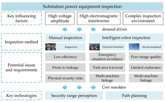
Figure 1.
Substation power equipment inspection task requirements and key technologies.
Inspection robots with real-time environment perception and intelligent path-planning technologies can shorten inspection times, save labor costs, and improve the autonomy and intelligence of the inspection process; therefore, robotic systems [9], especially mobile robots [10], have been promoted for use in power substations for a relatively long time. Currently, intelligent inspection robots are applied in substations, along transmission lines, and in other electric power scenarios, and each power substation in China with a voltage level higher than 110 kV has been equipped with at least one mobile inspection robot.
In the substation environment, robot inspection operations face many challenges, such as complex geographical environments, dense equipment layouts, and possible obstacles. In addition, the battery capacity and image quality of robots are factors that need to be considered. Insufficient battery capacity may require a robot to be frequently charged during the inspection process, affecting continuity. Poor image quality impacted by the complicated environment may also affect the robot’s perception ability and reduce the reliability of the inspection. Consequently, the aim of this article is to explore security range perception approaches and path-planning techniques for mobile robots in substations. Security range perception technology enables robots to identify potential safety hazards, while path-planning technologies allow robots to autonomously choose an optimal inspection route in substations, improving inspection efficiency and operational safety.
The rest of the paper is organized as follows: Basic inspection scenarios and details on the use of mobile robots in substations will be introduced in Section 2. A review and a discussion of the extensive security range perception methods and path-planning techniques that can be applied in power substations are provided in Section 3 and Section 4, respectively. A case study of intelligent robots based on safety range sensing and path-planning techniques is presented in Section 5. Finally, conclusions and future work are presented in Section 6.
2. Robot Inspection Scenarios in Substations
2.1. Inspection Scenarios in Substations
The content to be sensed by substation inspection robots can be divided into equipment operation and external invasion. During the monitoring process, it is essential to observe both primary and secondary equipment and assess the machinery’s operational status, including the “ON” status, the “OFF” status, and the fault levels.
The primary equipment for substations includes transformers, controllable reactors, and switchgear. Currently, the field of substation primary electrical equipment safety monitoring technology is highly developed. Insulation safety technologies comprise a significant focus for research. Since the 1970s, online monitoring of dissolved gasoline in transformers has been carried out. In recent years, the furfural content in transformer oil and the degree of polymerization in insulating paper have been proposed as the characteristic parameters for transformer fault diagnosis. Concurrently, the fault diagnosis of transformers, circuit breakers, and surge arresters based on condition monitoring data has been a hot research topic in recent years [11,12,13].
The monitoring of secondary equipment differs from that of primary equipment, which needs separate monitoring equipment. This can enable the tracking of the primary equipment. Because of microcomputer protection, secondary equipment usually has strong online self-testing and communication functions. Therefore, no additional monitoring equipment is required; instead, this equipment can use its self-testing and communication functions to complete condition monitoring tasks. Many studies have been conducted on monitoring the condition of substation secondary equipment [14,15].
Substation monitoring equipment can be divided into stationary and movable equipment. Stationary equipment entails the positioning of sensors in corresponding positions in a substation, allowing it to monitor equipment from a fixed position. This equipment is extremely inflexible and expensive to build and maintain. Consequently, the development of movable monitoring equipment represents a current research priority.
The operational status of substation equipment must be monitored, ensuring that its environmental characteristics, temperature changes, and other factors are tracked. This includes tracking the appearance, sound, temperature, and readiness of the equipment [16]. Accordingly, substation equipment must have sensors that can acquire and analyze data on the status of the devices, including visible, infrared, and acoustic data; these sensors can effectively detect relevant status indicators and abnormalities. Specific monitoring factors have been categorized here.
- Monitoring of remote equipment in substations
Substations have large footprints and dense equipment arrangements. To effectively monitor equipment in substations, high-precision, multi-preset, positioned, omnidirectional cameras are necessary. These cameras can be rotated in both the horizontal and vertical planes, allowing for precise positioning and enabling the monitoring of substations.
- Infrared monitoring of thermal defects in equipment
To prevent fires caused by elevated temperatures in substation equipment, such as transformers, circuit breakers, and cable joints, it is essential to implement an effective monitoring system for the temperature of this equipment. Infrared sensors can convert infrared radiation from substation equipment into heat-distribution images. These sensors can measure both temperature and the distribution of changes in surface temperature [17,18,19].
- Identification and monitoring of equipment status
Determining the operating state of the equipment in substations is another essential task in the monitoring process. For circuit breaker status recognition, it is first necessary to identify the area matching the corresponding equipment. Then, an image processing method is used to determine the state of the equipment [20]. Switch status recognition and meter reading recognition can also be realized by image recognition.
- Equipment anomaly monitoring
The primary purpose of equipment anomaly monitoring is to track the appearance and operation anomalies of power equipment in real time through image recognition algorithms [21]. The anomalies which commonly appear in power equipment include pollution and the attachment of foreign objects; meanwhile, operational anomalies include overheating, electrical leakage, and other problems. In practice, it is necessary to categorize and train models for detecting equipment abnormalities in advance and develop appropriate feedback strategies for the degree of abnormality that is detected.
2.2. Mobile Robots in Substations
At present, power-company substation inspection is based on the traditional manual method, which utilizes human vision, listening, smell, and other senses to obtain information and check and record the status of power equipment. This inspection method is characterized by high labor costs, personal safety risks, intense data subjectivity, and decentralized data management. With the gradual expansion of the power system and the introduction of the concept of an intelligent grid, countries worldwide have gradually increased their research into robot-conducted inspections.
As early as the 1980s, mobile robots were used to inspect power grids. Early inspection robots mainly focused on overhead transmission line inspection. In the past ten years, achievements in the field of robotics and artificial intelligence have strongly supported the development of inspection robot technology, and more and more inspection robots have been designed and applied in the inspection and monitoring of substations. Wheeled inspection robots are widely used to detect the working state of equipment because of their advantages in moving across large areas. Canadian researchers have developed a detection and operation robot [17] that has visual and infrared detection functions, adopts GPS positioning, and can remotely perform switching and closing operations, as shown in Figure 2a. The “SmartGuard” [22], shown in Figure 2b, also adopts a four-wheeled structure and is equipped with a visible-light camera and an infrared thermal imager, which can detect hotspots in substations. As shown in Figure 2c, the robotic inspection system developed by the China North Vehicle Research Institute uses magnetic navigation and frequency identification technology for positioning [23]. It supports multiple working modes, such as automatic inspection and remote control.

Figure 2.
(a) Visual inspection and intervention robot; (b) “SmartGuard” inspection robot; (c) inspection robot developed by the China North Vehicle Research Institute; (d) combined tire–track mobile robot; (e) inspection system based on drones; (f) track-type inspection robot.
In addition to the wheeled structure, inspection robots are also designed with other structures to adapt to the environment of a specific substation. For example, Figure 2d shows a combined tire–track mobile robot [24], which is thus equipped with an increased obstacle-crossing ability. Figure 2e shows a substation inspection system based on drones [25]. The system can conduct substation inspections when there is snow on the ground. Figure 2f shows a track-type inspection robot designed for a substation in Brazil [26]. This system transmits power and signals through the track, solving the robot power supply problem and the station’s electromagnetic interference.
Substation inspection robots involve several technological aspects. Regarding drive structure, inspection robots can be categorized into wheeled inspection robots, tracked inspection robots, orbital inspection robots, and flying inspection drones. Wheeled robots are the most common type, relying on omnidirectional, differential, or other wheels to move on the ground. Robots using this mobile platform have good smoothness and can move efficiently on flat surfaces. Tracked inspection robots use tank-like tracks to provide firmer grip and obstacle-crossing capabilities. They are suitable for working in rough road conditions, such as inspecting transmission lines in the field. The orbital inspection robots run on a pre-laid track, which frequently comprises a straight line, a curve, or three-dimensional structures. This type of movement has high positioning accuracy and stability and enables robots to move in narrow spaces, such as inside cable tunnels or pipelines. Unmanned aerial vehicles (UAVs) can move freely in the air and are not affected by obstacles on the ground. They carry sensors that provide aerial views of substation equipment and the surrounding environment. UAV inspection is fast and has a wide coverage area, making it suitable for quick-response and large-area inspection tasks, especially in emergencies, requiring the UAV to assess damages and the equipment’s condition quickly. Currently, wheeled mobile platforms are the mainstream solution for substation inspection robots.
In terms of sensors, mobile robots are equipped with sensors that mainly contain vision–sensing systems and partial discharge measurement devices. The task of the vision–sensing system is to act as the eyes of the robot, usually comprising two parts: a visible-light-sensing device and an infrared-sensing device. The visible-light sensor is mainly responsible for image recognition tasks, reading indicator numbers, indicator states, and switch positions while taking pictures of the equipment and observing fault phenomena, etc. The infrared thermal imager is mainly used to obtain equipment temperature information. A partial discharge detection device is primarily used to detect the electrical discharge between the insulating media of high-voltage switch cabinets. The primary detection methods include the optical detection method, the ultrasonic detection method, the transient ground wave detection method, the ultra-high-frequency method, and so on.
Environment perception and path planning are indispensable technologies for substation mobile robots, and this paper focuses on them.
3. Security Range Perception Methods
Intelligent inspection robots need the environment in which they are located to be sensed in advance, and the sensed information is used as the basis for path planning. This technique entails placing a robot in an unknown location in an unknown environment and using perceptual technology to gradually map the surrounding area and decide which direction the robot should go in. This technique is also known as simultaneous localization and mapping (SLAM). It was proposed by Randall C Smith and Peter Cheeseman in 1986 [27] and was later expanded by Leonard et al. [28]. With the expansion of sensor types and the emergence of structure-from-motion (SfM) technologies [29], SLAM techniques, based on different sensors and optimization theories, have been rapidly developed and widely used in the fields of augmented reality, virtual reality, and robotics [30,31].
Security range perception methods are divided into the overall map-building and monomer perception methods. The overall map-building method perceives the surrounding environment through sensors and corresponding algorithms. It builds a map of the scene, which can be further divided into local environment perception and environment advanced perception. Local environment sensing includes LiDAR and vision matching, and overall environment advance sensing includes multi-sensor fusion. The monomer perception method is a method of sensing a particular target in the surrounding environment and judging the surrounding environment in time. The method can also be categorized into overall environment advance sensing and local electrothermal coupling sensing. Overall environment advanced sensing includes radio frequency identification (RFID), ultra-wideband (UWB) sensing, and local electrothermal sensing, including electric field ranging and temperature sensing.
3.1. Global-Mapping-Based Range Perception Method
The global pre-mapping method allows a robot to construct a map of a substation in advance. This involves local environment perception and advanced environment perception. As a robot carries out its inspection tasks, the global map can be updated with the results of local map building, thus delineating the current safety scope in real time. The overall process is shown in Figure 3.
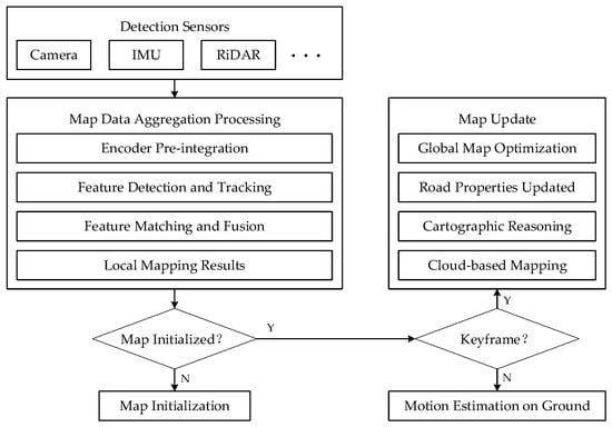
Figure 3.
Overview of global mapping method.
3.1.1. Local Environment Matching Method
The local environment matching method obtains information about a surrounding environment to determine the security range. This method includes visual matching and LiDAR, and its advantage is that it is not disturbed by other factors and can be perceived in real time.
- (1)
- Visual Matching
Since Bergen et al. introduced visual odometry (VO) in 2004 [32], researchers have been interested in methods for estimating camera motion based on visual image sequences. Introducing the map-building session into VO has greatly facilitated the development of visual SLAM techniques for constructing environment maps to reinforce data association. Considering that deep learning techniques have also been emphasized and applied in visual SLAM techniques in recent years, visual SLAM techniques can be divided into two categories: geometric transformation and deep learning.
Visual SLAM methods based on geometric transformation utilize the geometric structure mapping relationship between 2D images and 3D points to solve navigation parameters. This mainly involves two types of front-end theories: the feature point method and the direct method.
- Feature point method
The first visual SLAM was proposed in 2007, and it was the first method to obtain 3D motion trajectories from a moving camera [33]. However, the method’s single-threaded structure with real-time requirements limited the number of front-end features to be tracked. In contrast, Klein et al. [34] proposed a method with a two-threaded structure of tracking and map building, and camera trajectories and globally consistent environment maps were obtained using this method.
In recent years, visual SLAM based on the feature point method has mainly been used to improve the front-end feature structure. For example, in 2021, the Harbin Institute of Technology proposed point–line feature fusion [35], which combines line feature constraints to improve line feature estimation accuracy and reduce the impact of redundant parameters introduced by 3D line features in motion estimation.
- Direct method
In 2011, Newcombe et al. [36] proposed the first single-pixel-based direct method, SLAM, based on the dense tracking and mapping (DTAM) method combined with a single RGB camera for real-time target localization and tracking. Then, to preserve the critical point information to a certain extent, Forster et al. [37] proposed the semi-direct visual odometry (SVO) method, which has sparse feature points instead of conducting pixel matching. Afterwards, Engel et al. proposed the large-scale direct SLAM (LSD-SLAM) algorithm for constructing large-scale globally consistent maps of semi-dense environments [38]; additionally, they proposed the direct sparse odometry (DSO) method, which unifies data correlation and position estimation in nonlinear optimization by minimizing the photometric error in calculating the positions of cameras and map points [39].
Some researchers proposed a monocular-vision SLAM algorithm based on a semi-direct method [40]. It combines Kanade–Lucas–Tomasi (KLT) optical flow tracking with an oriented fast and rotated brief (ORB) feature-matching method, which can deal with the problems of low texture, moving targets, and perceptual aliasing in complex environments.
Meanwhile, the direct method, which studies combined geometric information, has also developed further. In 2019, the University of the Chinese Academy of Sciences proposed a fused MVG and direct SLAM (FMD-SLAM) algorithm [41]. It combines multi-view geometry and the direct method to estimate position information and optimizes positional results by minimizing the reprojection error.
However, the performance of visual SLAM methods through geometric transformations degrades during light transformation conditions, scene turnover, and object motion while suffering from high computational effort and fixed process patterns. Therefore, utilizing deep learning to replace some or all modules of SLAM is a current research hotspot.
CNN-SLAM, proposed by Canon in 2017, replaces the depth estimation and image-matching modules in LSD-SLAM with convolutional neural networks [42], effectively improving scene adaptability. An overview of CNN-SLAM is shown in Figure 4.
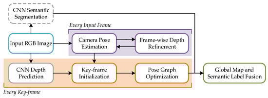
Figure 4.
System overview of CNN-SLAM.
CodeSLAM, proposed by the Imperial College in 2018, uses a U-Net neural network to extract image features and estimate the uncertainty of image depth [43]. A CNN-SVO method for depth prediction using a single image was proposed by the University of Botulla in 2019 [44]; this approach can improve the building effect of the semi-direct visual odometry method. In 2020, the University of Adelaide proposed a fused depth and flow for visual odometry (DF-VO) method based on CNN to achieve depth prediction and feature matching [45]; this combines deep learning with polarimetric geometry and PnP. In 2021, the University of Science and Technology of China (USTC) proposed the DP-SLAM method, which combines geometric constraints and semantic segmentation to remove moving objects in dynamic environments [46]. The method combines the moving probabilistic propagation model for dynamic keypoint detection, which is helpful in the applied research on virtual reality.
- (2)
- LiDAR
LiDAR can be divided into two types based on the number of laser lines: single-line LiDAR and multi-line LiDAR. Single-line LiDAR, also known as one-line scanning LiDAR, is the primary sensor of a 2D laser, which scans the environment from an angle, as determined by a single detector. It can only acquire point cloud data in one plane and cannot determine height information for 3D objects. Multi-line LiDAR, on the other hand, which is used in 3D lasers, uses multiple detectors to scan the environment from different angles simultaneously. It can also acquire point cloud data containing the coordinate information of 3D objects. Therefore, LiDAR can be categorized according to the type of laser and divided into 2D and 3D lasers. For 2D lasers, a raster map is generally used: the real environment is divided into a grid, and a 0–1 probability is used to indicate the probability that an object in the real environment occupies the grid; 3D lasers construct 3D point cloud maps, which are filtered using correlation filters.
- Two-dimensional lasers
Fast-SLAM [47] is a particle-filter-based SLAM algorithm proposed by Thrun et al. in 2002. Giorgio et al. [48] introduced the Rao–Blackwellized particle filter (RBPF) algorithm, which decomposes the SLAM problem into two independent subproblems: robot position estimation and the estimation of the posterior probability distributions of map coordinate points. Robot position estimation is realized using a particle filter, and the posterior probability distribution of the map coordinates is estimated by extended Kalman filtering. The algorithm adopts the particle-filtering technique, which can be processed for nonlinear systems.
Fast-SLAM requires more particles in order to achieve successful estimation in large environments or when the odometer error is large, which may cause memory explosion, and the resampling of particles will lead to particle dissipation. GMapping [48] improves Fast-SLAM by reducing the number of particles to alleviate memory explosion substantially. At the same time, it adopts a selective resampling method to rank the important weights of particles. It resamples particles with low weights to solve the particle dissipation problem in the RBPF algorithm. The GMapping algorithm has good real-time performance and high accuracy in indoor environments. It has continued to be one of the most commonly used SLAM algorithms since early developments in this field. However, GMapping is a filtering-based algorithm without loopback detection, which leads to a large cumulative error over a long period, and it cannot construct large environment maps outdoors.
Karto [49] is the first open-source SLAM algorithm based on graph optimization that considers a system’s sparsity. In the front-end part, a local map is composed of the current data frame and the neighboring data frames, and a correlative scan matching (CSM) [50] approach is used to achieve scan-to-map matching of the data frames to the local map to compute the bit position. The back-end part is globally optimized using a graph-based optimization approach. The closed-loop detection part uses candidate data frames to build local maps and uses the scan-to-map matching method. Hector-SLAM [51] uses the Gauss–Newton method to optimize the scan-to-map matching and builds raster maps without odometer information. However, due to the lack of loopback detection, a map cannot be corrected, and a map’s being wrong will affect the subsequent matching and map-building results. The scan-to-map approach is computationally intensive and requires the robot to move at a low speed to obtain better map-building results.
Google Maps was improved based on Karto, and Google proposed the Cartographer algorithm in 2016 [52]. It adds the functions of sensor synchronization, a position extrapolator, and laser data preprocessing. It introduces the concept of the submap, which uses a combination of CSM and gradient optimization to ensure that the frames match with the submaps to improve matching accuracy and efficiency. Submap construction is the iterative process of repeatedly aligning scan and submap coordinate frames, referred to as frames. The pose, ξ, of the scan frame in the submap frame is represented as the transformation, Tξ, which rigidly transforms the scan points from the scan frame into the submap frame; this is defined as follows:
A few consecutive scans are used to build a submap, which takes the form of probability grid M. We define a corresponding pixel for each grid point to consist of all the points closest to that point.
Before a scan is inserted into a submap, the scan pose, ξ, undergoes a rigorous optimization process about the current local submap using a Ceres-based scan matcher. This process ensures that the scan matcher finds a pose that maximizes the probabilities at the scan points in the submap, effectively solving nonlinear least-squares problems.
where Tξ transforms hk from the scan frame to the submap frame according to the scan pose. The function Msmooth: R2 → R is a smooth version of the probability values in the local submap. As a result, values outside the interval [0, 1] can occur, but they are considered harmless.
Utilizing the graph optimization algorithm, the current laser frame, and all previously created submaps, the Cartographer algorithm incorporates the branch and bound method, ensuring a confident boost in search speed [53]. The Cartographer algorithm is among a group of open-source SLAM algorithms with the best overall performances and the most convenient secondary development.
- Three-dimensional lasers
Zhang et al. proposed LiDAR odometry and mapping (LOAM) in 2014 [54]; this is a classic and representative algorithm, and many subsequent laser SLAM algorithms have borrowed its ideas. However, the LOAM algorithm lacks the back-end optimization and loopback detection module, such that it will generate drift in large-scale scenarios and scenarios with more loopbacks. Furthermore, the accuracy will be drastically reduced. In 2018, Shan et al. proposed LeGO-LOAM by adding a loopback-detection function based on LOAM [55]. It introduces the concept of keyframes and uses keyframes and their local range of data frames to form a loop submap. This can significantly reduce the computation time and achieves the purpose of loopback detection by matching the current data frames with the loop submap. LeGO-LOAM is a lightweight SLAM algorithm that is more robust and accurate than LOAM and requires less computation, but it also has its limitations. Compared to LOAM, LeGO-LOAM extracts features by projecting a 3D point cloud onto a 2D image to separate the ground and nonground points and remove noise, making the algorithm more demanding for the environment on the ground.
NASA proposed a direct laser odometry method for fast localization based on dense point clouds [56]. It stores keyframes and associated point clouds in a dictionary to save computational resources for frame–map matching, thus reducing the repetitive information in submaps based on keyframe composition. Meanwhile, a customized iterative nearest point solver, NanoGICP, has been proposed for lightweight point cloud matching with cross-object data sharing.
Extensive experiments demonstrate that the algorithm can process dense point cloud data in real time under high-speed conditions and improve localization accuracy.
While they perform well in most scenarios, uniform models designed to correct point cloud aberrations cannot adapt to scenarios with rapid changes in direction and speed. P-ICP is a resilient LiDAR mileage computation method with loopback which considers the continuity and discontinuity of interframe data to achieve more robustness in high-frequency violent motions. However, its loopback-detection part could be more constrained, limiting the sensor’s motion, and it has limitations in some application scenarios.
The authors of [57] proposed a pure-laser SLAM algorithm based on intensity information. The key is to utilize the intensity information of the point cloud to generate intensity images. Subsequent feature extraction and alignment, loopback detection, and position map estimation are all performed based on the intensity image.
Laser SLAM can also be optimized for performance by deep learning. The combination of deep learning and laser SLAM is mainly applied to several modules in the system, such as feature extraction and the alignment of point cloud, loopback detection, and the construction of semantic maps. The point cloud processing part is divided into two main categories: learning-based feature extraction and end-to-end point cloud alignment. These are based on a deep learning network. Accurate loopback detection has been a problem that laser SLAM needs to solve. Using deep learning to construct a reasonable network model, combined with extensive model training iterations, can enable the algorithm to extract critical feature information in the point cloud and improve the loopback accuracy.
OverlapNet [58] is a loopback detection algorithm designed for laser SLAM. It does not require the relative position of the two frames of point cloud data but instead utilizes the image overlap rate to detect loopbacks. The algorithm uses a depth map, an intensity map, a normal vector map, and a semantic map as the model inputs; then, it outputs predictions for the image overlap rate and the yaw angle. However, the algorithm’s accuracy decreases in cases of sudden environmental change. Although the locations are similar, the images mapped by the two LiDAR frames are very different at this time, and the overlap rate is low. OverlapTransformer [59] utilizes the same idea of the image overlap rate in OverlapNet to train the network. It requires only the distance image of the 3D point cloud projection, generates global descriptors, and uses the transformer structure to enhance the specificity of the global descriptors with yaw-angle rotation invariance.
3.1.2. Pre-Information-Based Mapping Method
The advantage of the pre-information-based mapping method is that a global map can be obtained in advance, without sensing the surroundings in real time, which aids in the efficiency of the approach. This method mainly involves the fusion of multiple sensors such as vision sensors, LiDAR, inertial measurement unit (IMU), etc.
The LIO-SAM algorithm is a classical, tightly coupled, laser–inertial odometry method based on smoothing and mapping [60]. It continues the idea of LOAM by extracting feature points and using IMU data to correct point cloud aberrations and provide the initial value of the bit position transformation between data frames. The back end uses a factor graph optimization architecture to eliminate cumulative errors and perform global optimization. To cope with fast motion, noise, and clutter in environmental conditions, Xu et al. proposed a highly computationally efficient, tightly coupled, laser–inertial odometry framework, FAST-LIO [61], which is shown in Figure 5.
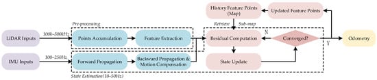
Figure 5.
System overview of FAST-LIO.
It uses an iterative Kalman filtering algorithm for the error states of the tightly coupled LiDAR and IMU, with forward propagation of state estimators for IMU data and backpropagation for the motion compensation of point cloud data. The authors also proposed a new formula for calculating the Kalman gain so that the computation is no longer dependent on the measurement dimension; rather, it is dependent on the state dimension, thus significantly reducing the computation.
FAST-LIO2 [62] is improved based on FAST-LIO. To adapt to LiDARs with different scanning modes and to achieve faster computation, FAST-LIO2 omits the time-consuming feature-extraction module and adopts a direct method for uniformly processing all the point cloud data and computing the point surface residuals.
In 2015, Bloesch et al. proposed a robust visual–inertial odometry (ROVIO) algorithm that directly utilizes image block pixel intensity errors for accurate tracking [63]. Leutenegger et al. [64] used keyframes to ensure that the old states maintained a bounded-sized optimization window, ensuring real-time operation. In 2018, the University of Pennsylvania proposed a binocular visual–inertial odometer, MSCKF-VIO, based on a multi-state constraint Kalman filter (MSCKF) [65]. The University of Freiburg proposed an attitude measurement algorithm that combines ORB-SLAM2-based visual attitude solving with inertial and GPS measurements and applies it in UAV rescue missions. In 2019, the Hong Kong University of Science and Technology proposed VINS-Fusion, an optimization-based multi-sensor state estimator [66] which is capable of supporting multiple types of visual and inertial sensors.
A multi-sensor fusion module consisting of LiDAR, IMU, and a camera is a popular combination for most scenarios. It usually consists of laser–inertial odometry (LIO) and visual–inertial odometry (VIO) and achieves coupling by integration with IMU [67].
The authors who proposed LIO-SAM also presented the LVI-SAM system by adding a camera sensor to the algorithm [68], which is shown in Figure 6. It consists of a laser–inertial system (LIS) and a visual–inertial system (VIS). The LIS provides accurate depth information for the VIS to improve the VIS accuracy, while the LIS utilizes the preliminary position estimation from the VIS for scan-matching purposes. The advantage of the algorithm is that LVI-SAM works even when the VIS or the LIS fails, which makes the algorithm robust in environments with low levels of texture or missing features.
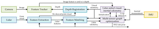
Figure 6.
The system structure of LVI-SAM.
Similarly, R2LIVE was proposed by Lin et al. [69] at the University of Hong Kong; this approach uses error-state iterative Kalman filtering to fuse the measurements from three sensors for state estimation. It is further optimized by a factor graph to improve the overall accuracy. However, its vision system uses the feature point method, which has a significant time overhead and is prone to failure in unstructured environments. To improve the real-time performance and accuracy of the algorithm, the authors reconfigured the vision system in the improved version of R3LIVE [70]. They used the optical flow method instead of the original feature point method for interframe tracking, fusing the visual data by minimizing the photometric error from the frame to the map, rendering the map in RGB colors.
In summary, the types and characteristics of several typical global-mapping-based range perception methods have been summarized and compared, as shown in Table 1.

Table 1.
Comparison of typical global-mapping-based range perception methods.
3.2. Regional-Sensing-Based Range Perception Method
The monomer perception method includes overall environment advance sensing and local electrothermal coupling sensing.
3.2.1. Pre-Information-Based Localization Method
The method acquires the position of every target in the environment in advance, mainly including RFID and UWB.
- (1)
- RFID
In RFID-based passive sensing research, the sensing scope, as the target of sensing technologies, often determines the choice of sensing channels and methods. It is the first element to be specified in the design of sensing applications. Many research studies have been carried out in different sensing categories to enhance the sensing capability of RFID in various categories. Among them, indoor localization has been the most essential and basic perception category in wireless perception.
In the early stage of the development of perception technology, a large number of research works were related to the indoor localization task of RFID tags [71,72].
Since then, RFID-tag-based indoor positioning technology has been further developed. MobiTagbot [73] further utilizes frequency-hopping (FH) technology to mitigate the impact of multi-path transmission on phase signals in real-world environments and to improve perception accuracy in real-world use.
Trajectory tracking is often considered an extension of localization techniques in the time dimension, which focuses on acquiring and recording the trajectories constituted by the target location points over time. Therefore, trajectory tracking is also an essential category in current perception research. Compared with indoor localization, trajectory tracking needs to track the dynamic position changes of a moving target accurately and thus has a broader range of application scenarios.
To address this issue, Liu et al. [74] proposed tracking the movement trajectories of workers in factories to effectively avoid production hazards caused by shortcuts taken by workers. Han et al. [75] detected the intrusion of unauthorized users in corridors, aisles, and other environments and tracked the movement trajectories of intruders. Yang et al. [76] and Wang et al. [77] proposed deploying tags on fingers or small objects and tracking the 2D motion trajectories of the tags through their phase signals. Shangguan et al. [78] deployed multiple tags on the same objects for tracking and tracing and proposed a set of solutions for tracking the motion trajectories of a single tag using a linearly polarized antenna [79]. Wei et al. [80] tracked the rotational trajectories of a target to achieve gyroscope-like rotation-angle sensing. Ding et al. [81] and Wang et al. [82] utilized an array of tags to achieve unbound fine-grained finger trajectory tracking. Bu et al. [83], Lin et al. [84], Jiang et al. [85], and Wang et al. [86] extended simple 2D trajectory tracking to synthesize the displacement and rotation of a target in 3D space. Wang et al. [87] and Jin et al. [88] attached labels to user’s limbs and tracked their limbs’ trajectories in three dimensions.
- (2)
- UWB
UWB technology has a higher positioning accuracy and is less susceptible to interference than RFID in narrow spaces, such as parking lots and tunnels. UWB positioning systems usually adopt the positioning algorithm based on distance information; the principle of this is to construct a system of equations based on the positional relationship between the base station, the target node, and the characteristics of its transmission signal and then obtain the target position information through the observation information between the base station and the target node. The localization algorithms relying on distance information mainly include the TOA, TDOA, and AOA algorithms. However, in complex environments, relying solely on one algorithm has various limitations, and multiple algorithms and navigation techniques must be combined to improve accuracy.
The authors of [89,90] fused the localization results of monocular ORB-SLAM with the position information solved by UWB through an extended Kalman filter (EKF), but this approach did not remove the errors that were not in the UWB’s line of sight.
UWB can also be combined with inertial sensors. Based on the traditional inertial–UWB tight combination framework, the authors of [91] added UWB anchor position information to system state variables. They estimated it through a data-fusion filter to reduce dependence on anchor information and improve environmental adaptability. There is a problem that arises here, where using only one-sided weak constraints at a distance to solve the position in tight combinations may lead to incorrect estimation; to solve this problem, the authors of [92] integrated UWB-based weak constraints on distance and strong constraints on position results with IMU measurements into a unified factor graph framework, thus improving the accuracy and stability of the system.
3.2.2. Real-Time Electrothermal Sensing Method
This method focuses on sensing surrounding information through electrothermally coupled sensors. It mainly consists of electric field and voltage sensors, infrared imaging technology, and thermocouple technology.
- (1)
- Electric Field and Voltage Sensors
Considering that the application scenario is a substation with many transformers, the real-time distance between the inspection robot and the relevant equipment can be measured by noncontact electric field and voltage sensors. The noncontact voltage and electric field measurement methods have higher degrees of safety, advantages in size and performance, and high application value. Among them, voltage sensors mainly include coupled capacitive and voltage sensors based on the current integration method.
Coupled capacitive voltage sensors are simple in principle and mature in application. Because no similar electromagnetic transformer exists in the core or other nonlinear materials, its measurement dynamic range is more comprehensive, and the insulation strength is higher. So, it can avoid the system between the ferromagnetic resonances and additionally play a role in carrier communication. However, although the capacitive sensor can monitor the line overvoltage signal, it tries to avoid the complex electromagnetic environment interference in the transmission process. To realize the long-distance transmission of the signal, the output overvoltage signal still needs to undergo active processing, which could affect measurement accuracy [93].
Voltage sensors based on the current integration method do not change the original structure and wiring of the grid. They can measure the current of the high-voltage capacitor through the current transformer. The current value can be inverted to calculate the change in the primary-side voltage. However, its reliability in obtaining the waveform is not sufficient.
The electrodes of a D-dot sensor are connected to a measuring resistor so that the induced charge produces an output voltage across the measuring resistor that is proportional to the rate of change in the electric field in the measurement space. The main structure of the sensor can be simplified to a first-order RC circuit, which can be adjusted to measure voltage signals from a few hertz to tens of megahertz by changing the circuit parameters. The equivalent circuit diagram is shown in Figure 7.
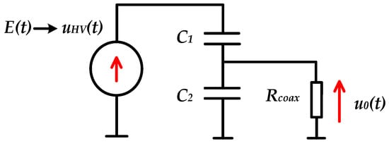
Figure 7.
D-dot sensor-equivalent diagram.
Because of its high-frequency transient response capability, the D-dot sensor is widely used in the transient voltage waveform measurements of some pulsed power devices. However, in practical applications, the placement of the sensor can lead to distortion of the spatial electric field, which affects the stability of the operation. Additionally, the electric field around the measured object can be easily disturbed by the environment [94]. Therefore, if this noncontact sensing method is to be promoted for the measurement and protection of power grids, further research on electromagnetic shielding, anti-interference, and other technologies is needed to improve the accuracy of the measurement [95].
- (2)
- Infrared Image Technology and Thermocouple Technology
When a substation fault causes some equipment to become hot, the specific locations of the heat sources must be detected promptly. The current methods for heat source identification mainly include infrared thermal imaging and thermocouple sensing technology.
Infrared image technology converts the temperature level and heat field distribution of a measured target into electrical signals, which are processed to form an image. The technology has been sufficiently validated and can now be integrated with other technologies. Zhang et al. [96] proposed Deep-IRTarget to address the issues of inadequate texture information and low-resolution detection targets in infrared images. The network utilizes the hypercomplex infrared Fourier transform approach to design a hypercomplex representation in the frequency domain to compute the significance of infrared intensity. A convolutional neural network extracts the feature mapping in the spatial domain. Afterward, the frequency and spatial domain features are superimposed to form a dual-domain feature. The architecture of Deep-IRTarget is shown in Figure 8.

Figure 8.
The architecture of the Deep-IRTarget framework.
Zhao et al. [97] proposed a model-based convolutional neural network model called Algorithm Unrolling Image Fusion (AUIF). The model can preserve the texture details of a visible image while preserving the thermal radiation information of an infrared image; this is the current state-of-the-art method.
A thermocouple is a temperature measurement element that can directly measure temperature, and its temperature measurement principle is the Seebeck effect. It consists of two metal conductors connected to form a closed metal junction. When there is a temperature difference between the two ends, a positively correlated current and thermoelectric potential are generated within the circuit with the temperature difference. The electric potential is measured using a potentiometer connected at the differential junction. The measured temperature is obtained by converting the magnitude of the electric potential. Kim et al. [98] measured radiative heat transfer over very small distances using a scanning probe embedded with a thermocouple and combined with a periodic temperature modulation device. Kou et al. [99] reviewed the current research on thermocouple technology for aero-engines, exploring armored thermocouple and thin-film thermocouple temperature measurements. Yang et al. [100] developed a semiconductor electrical energy emitter with a stacked electrothermal coupling design. This can effectively improve the performance of the electrothermal coupling.
The types and characteristics of several typical regional-sensing-based range perception methods were summarized and compared, as shown in Table 2.
Table 2.
Comparison of typical regional-sensing-based range perception methods.
3.3. Comparison and Analysis
According to the previous analysis, the various perceptual methods were organized, as shown in Table 3.
Table 3.
Characteristics and applicable scenarios of security range sensing techniques.
Different types of security range sensing technologies have their unique problems. A real-time environment matching method must recognize the surrounding environment in real time, so it needs strong computing capabilities. If faced with a complex environment, such a method will not be able to quickly obtain data on the surrounding environment, meaning that the inspection time of the robot will increase. The regional-sensing-based range perception method only needs to identify one situation. Therefore, it does not require high computing power compared to the real-time environment matching method. However, this method’s consideration of the environment or situation is very simple, and it cannot effectively obtain all the relevant information for the surrounding environment. When there is no clear distinction of this information in the environment, the environment cannot be effectively identified.
The global-mapping-based range perception method can sense the surrounding environment in real time. Additionally, due to the presence of more sensors, the sensing accuracy in the environment is also higher. However, the sensing process will become slower due to the need for more data. The regional-sensing-based range perception method acquires data on a certain environmental situation through only a certain type of sensor. This method is fast and accurate. However, it is unable to acquire more information; hence, it is unable to perceive the overall environment.
4. Path-Planning Techniques
Path-planning techniques include the global path-planning technique, based on prior information, and the regional path-planning technique, based on the method of sensing information [101]. The global path-planning technique depends on the prior security range information acquired by pre-information-based mapping and localization methods. Meanwhile, the regional path-planning technique requires real-time security range information, which is acquired by multiple sensors, including electric and thermal field measurement sensors.
4.1. Global Path Planning Based on Prior Information
Global path planning is a form of static planning. Mobile robots require all the map environment information in advance and synthesize prior information to carry out path planning. Therefore, this method is suitable for adapting the static environment. The algorithms used are the Dijkstra, RRT, A*, and genetic algorithms.
- Dijkstra algorithm
The Dijkstra algorithm is a classic algorithm used for finding the shortest paths between nodes in a graph, first introduced in 1956 by Edsger Wybe Dijkstra [102].
The main feature of the Dijkstra algorithm is outward expansion from the source node in iterations. To ensure that each step taken during the iteration is part of the shortest path, the algorithm selects, in each iteration, the nearest unvisited child node of the current node to proceed. Throughout the iterations, the algorithm updates the shortest paths from the source node to all the visited nodes, ensuring that the recorded path to any node is always the shortest one that has been found so far. This process continues until the shortest paths to all reachable nodes from the source have been determined. Over decades of development, Dijkstra’s algorithm has demonstrated remarkable competitiveness due to its high practicality. Numerous researchers have widely adopted it for practical applications. For instance, Google Maps employs this algorithm in autonomous driving navigation systems [103]. Wai et al. [104] utilized the algorithm to propose a mobile robot obstacle-avoidance path-planning system based on control, managing to achieve this goal without the demand of heavy computational resources or significant memory usage. Alshammrei et al. [105] improved the Dijkstra algorithm by effectively addressing optimal path planning in environments containing obstacles. In [106], Durakli et al. streamlined the algorithm’s structure, avoiding the necessity of incorporating any intermediate nodes, and incorporated Bezier curves to refine the paths, thus enhancing their smoothness.
In summary, the Dijkstra algorithm has a simple structure and good convergence properties. It has seen wide application in solving optimal path problems and evacuation scenarios. Nonetheless, this algorithm requires the traversal of many nodes, resulting in substantial computational demands, high algorithmic complexity, and greater memory consumption. As a result, its planning efficiency is not high.
- Rapidly exploring random tree algorithm
The rapidly exploring random tree algorithm [107] is a global planning algorithm. It is initiated from a starting point and randomly generates branches connecting to the trunk at the starting point, forming a search tree. This process continues until the tree branches connect with the target point. This algorithm is usually used for global path planning in single mobile robots, and diagrams of the principles of the algorithms are shown in Figure 9. The RRT* algorithm [108] is an extension of the RRT algorithm. When a new node is added, the RRT* algorithm revises the choice of parent nodes to ensure that the path corresponding to the latest node represents a local minimum. In essence, the RRT* algorithm continuously optimizes the already constructed tree structure as it explores the environment, thereby yielding more superior path solutions.
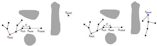
Figure 9.
Illustrations of the RRT and bidirectional RRT algorithms.
Currently, many researchers are studying the applications of RRT and its variants in path planning. Zhang et al. [109] proposed an adaptive hybrid algorithm that combines dynamic step lengths with target attraction for path planning, which addresses the issues of high randomness in the directionality of the search tree and inflexible step sizes in the RRT algorithm. Compared to the basic RRT algorithm, this method enhances the capability of passing through narrow corridors. It increases the traversal speed in open areas, showing notable improvements, i.e., reduced average path lengths and more favorable average branch numbers. Li et al. [110] proposed a PQ-RRT* hybrid algorithm, which combines the advantages of P-RRT* and Quick-RRT* to solve the problem of low efficiency caused by the slow convergence of the RRT algorithm in practical applications; experimental results showed the algorithm’s effectiveness. Wang et al. [111] proposed a kinematic, constrained, bidirectional, rapidly exploring random tree method, which adopted a more efficient branch-pruning strategy while retaining the advantages of bidirectional search, thereby improving the efficiency of the algorithm. To further improve the search speed of RRT, Hu et al. [112] proposed an RRT algorithm framework that can be used to plan the motion of wheeled robots under dynamic constraints. The algorithm framework uses a straight line to connect a pair of sampling path points to quickly find a barrier-free path and proposes a path-deformation strategy to move the path points away from the collision point so as to generate a trajectory without collision. The framework requires less computation and produces smoother, shorter trajectories. However, it is difficult for RRT to be used to achieve effective planning in narrow channels. Therefore, Li et al. [113] proposed an adaptive RRT-connected planning method, which retained the RRT planning method and added a rapidly exploring random vines (RRVs) algorithm. This method can effectively handle a narrow-channel environment.
- A* algorithm
The A* algorithm was proposed by Hart et al. in 1968 [114]. This algorithm involves an in-depth study of Dijkstra’s algorithm, adding heuristic information on the basis of Dijkstra’s algorithm and the searching weight function, as shown in Equation (3):
where g(n) is the cost of the distance from the starting point of node n and h(n) is the estimated cost of node n reaching the end point, namely, the heuristic function. The A* algorithm not only uses heuristic functions to improve the efficiency of the path search, but also guarantees that it does not extend more states than any other optimal algorithm given the same information. However, the real-time performance is poor, and with an increase in map size or dimensions, the planning time increases exponentially.
Wang et al. [115] proposed an improved A* algorithm. By weighting the heuristic function, the computing efficiency was improved, the processing time was shortened, and the road cost was effectively reduced. However, there were still limitations, such as the presence of a long path. Li et al. [116] proposed an improved bidirectional A* algorithm. Based on the A* algorithm, the algorithm introduces a bidirectional alternate search strategy, searching from the starting point and the end point, respectively, until the paths meet, thus improving the search efficiency of the algorithm. Erke et al. [117] proposed a criterion generated by global planning for enhancing the A* algorithm with a heuristic function and a variable step size. The proposed improved algorithm has better robustness and stability than the original algorithm. There are also many variants and improvement schemes for the A* algorithm. For example, the ARA* (anytime repairing A*) algorithm [118] quickly plans an initial path; then, it continuously optimizes this path as time allows, considering the balance between computation time and path quality. The LPA* (lifelong planning A*) algorithm can utilize previously stored information when the environment changes, allowing the original A* algorithm to be applied to dynamic environments.
- Genetic algorithm
Holland proposed the genetic algorithm in 1962 [119]. Based on the bionics principle, it manipulates potential solutions to solve a given problem by simulating the biological evolution process, such as selection, crossover, and mutation. This algorithm has strong global search ability and efficient parallel processing ability and is easy to implement through programming, so it is widely used in path planning.
Pehlivanoglu et al. [120] proposed a more efficient initial population generation method, which accelerated the convergence process of the algorithm. Lee et al. [121] proposed a method based on directed acyclic graphs, which also improved the performance of the GA algorithm by improving the population initialization method. Chen et al. [122] combined a genetic algorithm with fuzzy logic control (FLC) to control a wheeled mobile robot. The experimental results show that robots using this approach can move stably in an environment with obstacles. Nazarahari et al. [123] combined an artificial potential field (APF) algorithm with an improved genetic algorithm to propose a hybrid method for the path planning of multiple mobile robots in a continuous environment. The flowchart of this method is shown in Figure 10.

Figure 10.
Enhanced GA flowchart for optimal path planning in a continuous environment.
The genetic algorithm introduces a collision-removal operator to avoid possible collisions in multi-robot paths. The experimental results show that the algorithm not only determines the collision-free path but also finds the near optimal solution for all robots.
4.2. Regional Path Planning Based on Sensing Information
Regional path planning belongs to dynamic planning. The inspection robot’s internal sensors collect the environment’s map information in real time, determine the obstacle distributions, and select the best path from the current node to the target node. The algorithms applied to this problem include the artificial potential field method (APF), the D* algorithm, ant colony optimization, and the reinforcement learning method.
- Artificial potential field method
The artificial potential field (APF) method was first proposed by Khatib in 1985 [124]. This method solves the path-planning problem by transforming it into finding the optimal path from the starting point to the target point in a virtual “potential field” composed of attractive and repulsive forces, as shown in Figure 11. The core idea of the artificial potential field method is to simulate the behavior of particles in the force field of a physical system and to use this analogy to guide the navigation of robots.
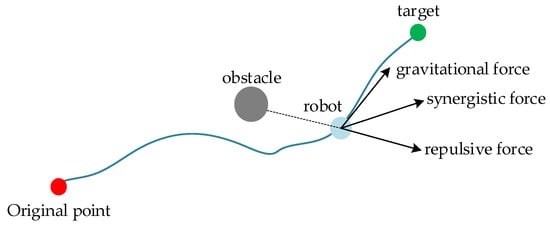
Figure 11.
Principle diagram of the APF method.
The artificial potential field method is simple in structure, is easy to calculate, and has significant advantages in dealing with real-time dynamic obstacle avoidance path planning. Abdalla et al. [125] proposed a method combining the improved APF algorithm with fuzzy logic to overcome the local minimum problem in the traditional APF algorithm. Compared with using the traditional method, a robot using this algorithm can move more smoothly and quickly. Duhe et al. [126] proposed four alternative formulas for the repulsion field: correction polynomials, tangential and radial components, Poisson potential, and pseudo-fractional potential. These effectively reduced oscillation when the mobile robot approached an obstacle and made a given planned path more stable. Jayaweera [127] proposed a dynamic flight path-planning method based on APF, which enables UAVs to follow moving targets on the ground while avoiding obstacles on the flight path. Liu et al. [128] proposed an adaptive path-planning system with the fusion of two potential fields. A new potential field is constructed using velocity information, as shown in Figure 12.
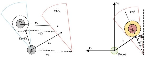
Figure 12.
Depictions of velocity obstacles and the novel velocity region model.
In Figure 12, A is a robot and B is a moving obstacle. PA and PB are the reference points of A and B, respectively. VA and VB are their velocities. The dotted circle indicates the safe range for A and B not to collide. A velocity region can be obtained from the location of A and the dashed circle. VOAB can be obtained by shifting this velocity region along VB. If VA is inside VOAB, then A and B will collide at some point in time, and if VA is outside VOAB, then the objects will never collide. Hence, VOAB is defined as the velocity obstacle of B to A. According to this principle, the velocity region model is established. In this model, VOAB is expressed as an original velocity region, denoted as VR0. The subscript i represents the ith obstacle. α is the azimuth angle of the obstacle. β is the half-angle of VR0.
- D* algorithm
The D* algorithm (D-star algorithm), introduced by Stuart Russell in 1995 [129], is a dynamic path-planning algorithm primarily designed for robotic navigation scenarios in which the environment is subject to change. It merges the advantages of both the Dijkstra and A* algorithms, efficiently recalculating the shortest path from the start point to the goal in response to environmental dynamics without restarting the search from scratch. Central to its operation is the maintenance of estimated costs for nodes, allowing the algorithm to swiftly adapt when changes occur in the environment (such as the emergence of new obstacles or the removal of existing ones). By only updating the affected portions of the path, D* significantly conserves computational resources.
At present, improving the D* algorithm mainly requires a focus on improving path smoothness and improving search efficiency. Yu et al. [130] proposed a path-planning algorithm based on the improved D*Lite algorithm. In this algorithm, the path cost function is improved to reduce the expansion range of nodes, and the node expansion direction is limited to avoid double-node computation. The Dubins algorithm was also introduced for a smoother planning path. Ren et al. [131] presented a new multi-objective incremental search algorithm. A suboptimal variant of MOPBD* was introduced to improve search efficiency, and the algorithm achieves the advantage of being one order of magnitude faster than the existing incremental methods of multi-objective path planning. Sun et al. [132] added the obstacle cost term and the steering-angle cost term as constraint conditions based on the original cost function to ensure the safety of navigation. Through simulation experiments, the reliability of the algorithm was verified on an underwater mobile robot (AUV).
Overall, the D* algorithm, despite being computationally intensive and having nonsmooth paths, is highly reliable in dealing with dynamic obstacle problems and is often used for dynamic planning problems in unknown environments.
- Ant colony optimization
Ant colony optimization (ACO), inspired by the foraging behavior of ants, is a metaheuristic optimization algorithm initially introduced by Italian researcher Marco Dorigo in 1991 [133]. It models the process in which ants secrete pheromones and use them to find the shortest paths to food sources; this principle can be utilized to address dynamic path-planning problems. In the ACO algorithm, a colony of virtual ants navigates a graph, with each ant deciding its next move based on the concentration of pheromones deposited by previous ants and the path length. Pheromones evaporate over time, but those laid on shorter paths become more concentrated, creating a positive feedback loop and reinforcing the better paths. Through multiple iterations, the algorithm eventually finds the shortest path that visits all other points from the starting point and returns. A diagram of the principles of this algorithm is shown in Figure 13.

Figure 13.
Principle diagram of the ACO algorithm.
The ant colony algorithm is a typical intelligent optimization algorithm with strong robustness in path planning, but it has some shortcomings, such as local optimality and slow convergence. Luo et al. [134] introduced an improved ACO algorithm that constructs unequal allocation initial pheromones and uses a pseudo-random state transition rule to solve the problems of local optima, slow convergence speed, and low search efficiency.
Wang et al. [135] introduced the Floyd algorithm to generate a guiding path and increase the pheromone content on the guiding path. The difference in pheromone concentration can guide the ant colony to find the target node quickly. Miao et al. [136] introduced the angle guidance factor and the obstacle exclusion factor into the transfer probability of ACO to accelerate the real-time safety of robot path planning. They introduced multi-objective performance indexes to transform the path-planning problem into a multi-objective optimization problem. Dai et al. [137] introduced the evaluation function and bending suppression operator of the A* algorithm, improved the heuristic information of the ant colony algorithm, accelerated the convergence speed, and increased the smoothness of the global path.
- Reinforcement learning
- Based on reinforcement learning, path-planning algorithms enable agents to learn optimal paths through interaction with their environment. Agents take actions based on states to maximize cumulative rewards. These techniques include Q-learning, deep Q-networks (DQN), and policy gradient methods. They are widely applied in robotic navigation, autonomous driving, and game AI, effectively addressing path-planning problems in complex environments. As algorithms continue to advance and computational power increases, the application of reinforcement learning in path planning is becoming increasingly mature and widespread.
- Song et al. [138] proposed an improved Q-learning algorithm to solve the problem of Q-learning converging slowly to the optimal solution. The pollination algorithm is used to improve Q-learning initialization. The experimental results show that the proper initialization of the Q-value can accelerate the convergence of Q-learning. Zhao et al. [139] proposed an empirical memory learning (EMQL) algorithm based on the continuous update of the shortest distance from the current state node to the start point, which outperforms the traditional Q-learning algorithm regarding the planning time, the number of iterations, and the path length achieved. Wang et al. [140] proposed a reinforcement learning approach using an improved exploration mechanism (IEM) based on prioritized experience replay (PER) and curiosity-driven exploration (CDE) for the problem of time-constrained path planning for UAVs operating in a complex unknown environment. Compared with the original off-policy RL algorithm, an algorithm incorporating IEM can reduce the planning time of the rescue path and achieve the goal of rescuing all trapped individuals. Bai et al. [141] used the double deep Q-network (DDQN) to obtain the adaptive optimal path-planning solution. They designed a comprehensive reward function integrated with a heuristic function to navigate a robot into a target area. A greedy strategy and optimized DNN are used to improve the global search capability and the convergence speed of the DDQN algorithm.
4.3. Path Planning for Multi-Robot Systems
Path planning for multi-robot systems refers to a method for planning and scheduling of one or more robots under the path-planning algorithm. Considering that the complicated tasks require multiple robots to cooperate with each other, the path-planning algorithms that can simultaneously navigate multiple robots are consistently improved based on various optimization methodologies.
- Tran et al. [142] proposed a new swarm-based control algorithm for multi-robot exploration and repeated coverage in an unknown dynamic obstacle environment. A series of comparative experiments verified the effectiveness of the strategy. Xie et al. [143] proposed an autonomous multi-robot navigation and collaborative SLAM system architecture, including multi-robot planning and local navigation. This architecture realizes multi-robot collaborative environment detection and path planning without a prior navigation map. Similarly, Zhang et al. [144] applied the particle swarm optimization algorithm (PSO) to the robot swarm situation and proposed a moving-distance-minimized PSO for mobile robot swarms (MPSO). The algorithm uses the principle of PSO to deduce the moving distance of the robot crowd so that the total moving distance is minimized. On this basis, Zhang et al. [145] proposed a PSO algorithm based on virtual sources and virtual groups (VVPSO), which divides the search area into multiple units on average, with one virtual source in the center of each unit. A new particle swarm called real–virtual mapping PSO (RMPSO) searches the corresponding units to locate the real source. It can map the robot asymmetrically to a particle swarm with multiple virtual particles for particle swarm optimization. This approach dramatically advances the field of multi-source localization using mobile robot crowds. However, the environment in which the robot moves changes in real time, so the ability of the robot to handle both bounded and unbounded environments is essential. Inspired by animal group foraging behavior, Zhang et al. [146] proposed a dual-environment herd-foraging-based coverage path-planning algorithm (DH-CPP). It enables swarm robots to handle bounded and unbounded environments without prior knowledge of environmental information.
4.4. Comparison of Path-Planning Algorithms
The equipment in a substation requires long-term and real-time inspection and monitoring and has different priorities according to maintenance levels and operation statuses. Therefore, the global path-planning problem is a multi-objective optimization problem that includes the shortest path, the lowest energy consumption, multiple destinations, and different target priorities. The traditional Dijkstra algorithm, the A* algorithm, and the RRT algorithm are suitable for efficiently acquiring the shortest path between a pair of target points and the starting point with a single optimization objective. Meanwhile, the ACO algorithm can perform multi-objective optimization for the scenarios with discrete target points. Genetic algorithms can obtain a solution by searching for individuals who meet multiple optimization goals. Therefore, they have better performances in solving the global path-planning problems of substations when compared with the traditional path-planning algorithms.
After the global inspection route is planned, a robot must adopt real-time dynamic obstacle avoidance and path-planning algorithms in the inspection process; appropriate choices include the artificial potential field method algorithms, i.e., the APF and D* algorithms. This is because the security range and equipment operation status in substations change dynamically.
In summary, inspection robots need to apply algorithm combinations in the working process and complete path-planning tasks by leveraging the strengths of different strategies. Table 4 shows a comparison of different path-planning algorithms.
Table 4.
Comparison of different path-planning algorithms.
5. Case Study
To realize the automatic identification, positioning, tracking, and dynamic supervision of all state information in the substation site selected for this case study, it is necessary to combine the use of various intelligent technologies, such as RFID, LiDAR positioning, and audiovisual perception; this will enable the ultimate realization of the integration of control and management in the substation based on intelligent inspection.
5.1. Practical Application Cases
Considering the differences in actual substation environments, selecting appropriate security range perception and path-planning methods is necessary.
5.1.1. Practical Application of Security Range Perception
In most cases, the substation environment will not change. Therefore, the perception of security ranges in most scenarios can be realized by using the pre-information-based mapping method. When the substation environment changes, the real-time environment matching method is needed to sense the surrounding environment in real time. Li et al. [147] proposed a monocular vision method based on 2D–3D fusion. Specifically, the method uses instance segmentation, depth estimation, depth reconstruction, and back-projection transformation to predict the three-dimensional distances of objects in two-dimensional images. This method is a typical real-time environment matching method, which can meet the requirement to attain a low-cost, easily maintained approach that enables the real-time, safe, distanced sensing of substations. The maximum error of this method is less than 9%, and the average error rate on the power transformer–human dataset is 5.34%.
When it is necessary to identify a particular situation in the substation, the regional-sensing-based range perception method should be adopted. If the substation is installed within a UWB base station, then UWB can be used for security range perception. To recognize some characteristics of a substation, such as voltage and temperature, the real-time electrothermal sensing method can be used for recognition and perception. Cai et al. [148] determined that the safe distance for UAV operation under 500 kV is about 2.1 m.
5.1.2. Practical Application of Path Planning
Considering that the RRT algorithm can quickly complete real-time online path-planning tasks in complex environments, it has been widely used in real-time path-planning problems for the inspection of UAVs and unmanned vehicles in dynamic environments. In 2021, Wu et al. [149] selected the RRT algorithm as an adaptive path-planning method for the collaborative operation of UAVs in dynamic environments; they realized the generation of optimal 3D paths for UAVs. Their work divided the UAV low-altitude flight area into many cubes of the same size. Only the vertices of each cube can be used as the growth points of the spanning tree, i.e., the waypoints for the drones’ planned paths. During the flight, a UAV has to comply with the flight rules: the path points must be at a certain distance from the buildings, and the time intervals between arriving at the destination and passing through the same path point must be greater than a specific value. In addition, obstacles, such as no-fly zones caused by accidents, weather, or birds, mean that drones taking off in emergencies should be monitored at regular intervals, and the 3D path to the destination should be constantly adjusted using the RRT algorithm. The time and length size of the generated paths are essential in this process. Consequently, the authors compared the performance of A*, ACO, and RRT algorithms in generating drone flight paths under the same simulation conditions. The size of the simulated UAV low-altitude flight area was 1800 m × 1800 m × 90 m. The time interval for the UAV’s detection of obstacles was 0.1 s. The starting point was (750, 810, 60), and the endpoint was (1770, 1710, 90). Among the algorithms, ACO planned the longest detouring path at 7481.1 m, while A* and RRT produced paths of 1405.2 m and 1421.4 m, respectively, indicating that ACO’s path was suboptimal. Notably, A* required 3.66 s to find the optimal path, which was significantly longer than the 0.12 s duration needed by RRT. In summary, utilizing the RRT algorithm for real-time 3D path generation enhances drone efficiency and reduces accident risks.
The ACO algorithm can be extended to the path-planning problem of multi-robot cooperative inspection. Each robot can be regarded as an “ant” that searches for paths and releases pheromones in a shared environment. Robots can work together to find the optimal inspection path by exchanging and sharing pheromones. In 2022, Sun. [150] proposed a strategy of high-altitude, low-altitude, and on-the-ground inspection based on the ACO algorithm with the cooperation of UAVs and intelligent robots in a 220 kV substation. The 220 kV substation is equipped with three three-phase transformers. The voltage levels of each side are 220 kV, 110 kV, and 120 kV. The primary inspection is divided into the following aspects: (1) the 220 kV equipment area, including circuit breakers, disconnect switches, voltage, current transformers, surge arresters, outgoing connectors, and other pieces of substation equipment; (2) the 110 kV equipment area, including circuit breakers, disconnect switches, voltage, current transformers, SF6 pressure gauges, surge arresters, grounding knife status, contacts, etc.; (3) the transformer main equipment area, including a dedicated fire protection system, relays, oil thermometers, oil level meters, etc. In his work, a combination of UAV scanning and grid-based methods was first used to construct a 2D simulation map of the substation. Then, the ACO algorithm was employed to achieve optimal path planning for UAVs and intelligent robots. In the 220 kV substation inspection experiment, the following ACO algorithm parameters were set: the information heuristic factor was 1, the expectation heuristic factor was 7, the pheromone evaporation rate was 0.3, the number of ant colonies was 50, and the number of iterations was 100. The final simulation results demonstrated that the collaborative inspection strategy using the ACO algorithm enabled UAVs and intelligent robots to achieve better safety, timeliness, and comprehensive, real-time monitoring effects.
5.2. Security Range Control and Path Planning
Research on safety range control technologies in substation scenarios is still in its infancy. When an inspection robot senses and plans its safety range in real time, electronic and physical fences are used for isolation, control, and auxiliary monitoring for substation operations. Therefore, a novel group of physical fences is introduced to automatically complete the dynamic adjustment of the range of different safety areas inside the substation under the optimization goals of low cost and high efficiency. The self-network construction and group path-planning techniques are crucial to realizing the intelligent control and management of the substation.
Figure 14 illustrates the novel substation fencing deployment system architecture that possesses real-time environment sensing and path-planning capabilities and can dynamically adjust the control range of the secure area based on the results. The system mainly consists of a control computer module, a human–computer interaction module, a multi-sensor module, a mobile module, a power supply module, and a fence deployment module.
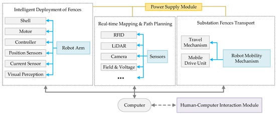
Figure 14.
The architecture of the substation fence-laying system based on intelligent inspection.
The control computer module is responsible for coordinating the calculations and control links with other modules while implementing cascading control with the human–computer interaction module. The multi-sensor module includes IMU, LiDAR, a depth camera, and an information fusion unit; these elements comprise the sensing carrier of the SLAM intelligent navigation system and the automatic planning system. The mobile module includes a mobile drive unit and a mechanical travel mechanism. The power supply module provides power supply to other module parts. A robotic arm is mainly used to install the fence and is equipped with a visual recognition and positioning module.
When the SLAM function module is working, other function modules are not enabled or are in standby mode to avoid electromagnetic interference problems between modules to a certain extent. The communication and data transmission between the robot’s internal modules is anti-interference and transmitted using shielded cables to prevent electromagnetic interference effectively. The circuit modules are encapsulated with metal parts with an electromagnetic shielding function, and the sealing shielding at the cable outlet is ensured to achieve the shielding of the wires.
The operation process of an intelligent robot for substation security range control is shown in Figure 15. Sensors installed on the inspection robot can collect data from the vehicle’s surrounding environment and extract data features through deep neural networks. Thus, the robot perceives the surrounding environmental information and equipment operation and delineates potentially dangerous areas. Based on pre-mapping and real-time information, the path-planning process achieves an optimal path within the safety range according to a predetermined path-search algorithm through a satellite positioning system. Based on this path, the fence automatically arranges devices using laser radars and other equipment to determine the road and obstacle information on the environment map. The fences move according to the group SLAM algorithm and reasonably adjust the layout in the risk area to realize the dynamic control of the substation, as shown in Figure 16.
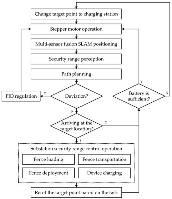
Figure 15.
Operation process of intelligent robot for substation security range control.
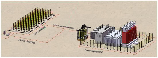
Figure 16.
Operational simulation of an electronic fence and intelligent deployment robot for risk-area control in substation scenarios.
6. Conclusions
This manuscript outlines the application of intelligent inspection robots in typical electric power scenarios. It reviews the current research status of the critical technologies of security range sensing and path planning for intelligent inspection robots in power substations. A case study of intelligent robots based on security range sensing and path-planning techniques is also presented to introduce the novel control and management method for substations.
Overall, the application of inspection robots in substations can reduce staff labor intensity, improve work efficiency, and carry specific external modules for linkage control to achieve downstream tasks such as transporting and deploying substation fences. However, breakthroughs could be achieved in the following aspects.
- (1)
- Real-time sensing technology for the state of substation equipment operations
By installing and deploying intelligent sensors, we can realize the multi-dimensional real-time monitoring of substation equipment and operating environments to obtain essential state quantities; further, we can provide supporting data for the state perception of the necessary equipment.
- Integration at the technical level
Real-time monitoring of sensory equipment generates a large amount of data. On the one hand, artificial intelligence and big data technology, focusing on the study of distributed machine learning, online learning, incremental learning, and other technologies, can improve the scalability and operation of real-time multi-sensor sensing technology. On the other hand, AI, with edge computing technology, can reduce power consumption. Part of the information should also be localized as much as possible to reduce communication pressure and cloud load.
- Integration at the method level
Expert systems, traditional machine learning, and deep learning methods have advantages in terms of interpretability, computational volume, required sample size, fault tolerance, learning ability, and ease of use. However, the state information of substation power equipment has an exact physical meaning, and fault diagnosis is highly specialized. Therefore, the research on integrated inspection control systems is interpretable, interactive, and operable. Attempts can be made to incorporate other methods with expert systems to construct an expert system based on a knowledge graph with a self-learning ability that is characterized by robustness.
- (2)
- Three-dimensional panoramic visualization of substations
Three-dimensional panoramic visualization of a substation is the primary expression of the remote monitoring system, which can visualize the real-time situation of the equipment, environment, and personnel in a substation.
- Three-dimensional modeling technology of substations
The 3D spatial coordinate system of a substation is the basis for realizing a robot’s security range perception and path planning, as well as the carrier of substation state visualization. Therefore, the modeling method at both the macro- and micro-scales can be considered as follows: First, a macro-model of a substation can be established by using sensing equipment and architectural drawings. Second, equipment models can be constructed from a micro-level view to form a reusable model library. Third, the location of the equipment can be determined according to layout plans.
- Equipment abnormal state identification and localization technology
Equipment abnormal state perception is based on the state information obtained by the sensor group. It relies on the real-time analysis of state information to identify temperature, appearance, smoke, open-flame, and other visualization states. In an automated inspection task, an intelligent robot can determine its safe operation range through positioning technology, carry out inspection path planning in the appropriate zone, monitor the abnormal state of power equipment in real time, and make adjustments to the safety zone and inspection path.
- Risk-area control strategy
The risk area mainly includes the abnormal power equipment perceived by the intelligent robot, the control area planned by humans, and the risk level, which can be divided according to the type of abnormal situation. Low-risk regions are isolated by manually deploying electronic fences and controlled by alarm signs and sound warnings. For high-risk areas characterized by electrical leaks, fires, and other emergencies, it is necessary to develop fixed isolation barrier automatic deployment technology based on carrier robots to avoid the safety hazards of manual work.
Author Contributions
Conceptualization and methodology, J.Z. and T.C.; formal analysis, investigation, resources, and writing—original draft preparation, J.Z. and J.H.; review and editing and visualization, Z.W. and B.G.; project administration and supervision, B.G. All authors have read and agreed to the published version of the manuscript.
Funding
This work was supported by the Science and Technology Project of the State Grid Jiangsu Electric Power Company (J2024040).
Data Availability Statement
The data used in this study are publicly available, and sources are referred to in the text.
Conflicts of Interest
Authors Jianhua Zheng, Tong Chen and Zhunian Wang were employed by the company State Grid Zhenjiang Electric Power Co., Ltd. The remaining authors declare that the research was conducted in the absence of any commercial or financial relationships that could be construed as a potential conflict of interest.
References
- Zhou, M.K.; Yan, J.F.; Zhou, X.X. Real-time online analysis of power grid. CSEE J. Power Energy Syst. 2020, 6, 236–238. [Google Scholar]
- Wen, M.; Li, Y.; Xie, X.T.; Cao, Y.J.; Wu, Y.W.; Wang, W.Y.; He, L.; Cao, Y.; Xu, B.K.; Huang, L.M. Key factors for efficient consumption of renewable energy in a provincial power grid in southern China. CSEE J. Power Energy Syst. 2020, 6, 554–562. [Google Scholar]
- Feng, D.; Lin, S.; He, Z.Y.; Sun, X.J.; Wang, Z. Failure risk interval estimation of traction power supply equipment considering the impact of multiple factors. IEEE Trans. Transp. Electrif. 2018, 4, 389–398. [Google Scholar] [CrossRef]
- Leo Kumar, S.P. State of the art-intense review on artificial intelligence systems application in process planning and manufacturing. Eng. Appl. Artif. Intell. 2017, 65, 294–329. [Google Scholar] [CrossRef]
- Chen, D.Q.; Guo, X.H.; Huang, P.; Li, F.H. Safety distance analysis of 500 kV transmission line tower UAV patrol inspection. IEEE Lett. Electromagn. Compat. Pract. Appl. 2020, 2, 124–128. [Google Scholar] [CrossRef]
- Li, S.F.; Hou, X.Z. Research on the AGV based robot system used in substation inspection. In Proceedings of the International Conference on Power System Technology, Chongqing, China, 22–26 October 2006; pp. 1–4. [Google Scholar]
- Katrasnik, J.; Pernus, F.; Likar, B. A survey of mobile robots for distribution power line inspection. IEEE Trans. Power Deliv. 2010, 25, 485–493. [Google Scholar] [CrossRef]
- Zhang, H.J.; Su, B.; Song, H.P.; Xiong, W. Development and implement of an inspection robot for power substation. In Proceedings of the 2015 IEEE Intelligent Vehicles Symposium, Seoul, Republic of Korea, 28 June–1 July 2015; pp. 121–125. [Google Scholar]
- Allan, J.F.; Beaudry, J. Robotic systems applied to power substations—A state-of-the-art survey. In Proceedings of the 2014 3rd International Conference on Applied Robotics for the Power Industry, Foz do Iguacu, Brazil, 14–16 October 2014; pp. 1–6. [Google Scholar]
- Lu, S.Y.; Zhang, Y.; Su, J.J. Mobile robot for power substation inspection: A survey. IEEE/CAA J. Autom. Sin. 2017, 4, 830–847. [Google Scholar] [CrossRef]
- Tang, J.; Zhou, Q.; Tang, M.; Xie, Y. Study on Mathematical model for VHF partial discharge of typical insulated defects in GIS. IEEE Trans. Dielect. Electr. Insul. 2007, 14, 30–38. [Google Scholar] [CrossRef]
- Xu, Z.R.; Tang, J.; Sun, C.X. Application of complex wavelet transform to suppress white noise in GIS UHF PD signals. IEEE Trans. Power Deliv. 2007, 22, 1498–1504. [Google Scholar]
- Li, J.; Sun, C.X.; Grzybowski, S. Partial discharge image recognition influenced by fractal image compression. IEEE Trans. Dielect. Electr. Insul. 2008, 15, 496–504. [Google Scholar]
- Li, J.; He, Z.M.; Bao, L.W.; Wang, Y.Y.; Du, L. Condition monitoring of high voltage equipment in smart grid. In Proceedings of the 2012 International Conference on High Voltage Engineering and Application, Shanghai, China, 17–20 September 2012; pp. 608–612. [Google Scholar]
- Yan, H.; Gao, G.; Huang, J.; Cao, Y. Study on the condition monitoring of equipment power system based on improved control chart. In Proceedings of the 2012 International Conference on Quality, Reliability, Risk, Maintenance, and Safety Engineering, Chengdu, China, 15–18 June 2012; pp. 735–739. [Google Scholar]
- Chaumette, F.; Hutchinson, S. Visual servo control. I. basic approaches. IEEE Robot. Automat. Mag. 2006, 13, 82–90. [Google Scholar] [CrossRef]
- Guo, R.; Li, B.; Sun, Y.; Han, L. A patrol robot for electric power substation. In Proceedings of the 2009 IEEE International Conference on Mechatronics and Automation, New York, NY, USA, 9–12 August 2009; pp. 55–59. [Google Scholar]
- Guo, L.; Liu, S.; Lv, M.; Ma, J.; Xie, L.; Yang, Q. Analysis on internal defects of electrical equipments in substation using heating simulation for infrared diagnose using heating simulation for infrared diagnose. In Proceedings of the 2014 China International Conference on Electricity Distribution (CICED), Shenzhen, China, 23–26 September 2014; pp. 39–42. [Google Scholar]
- Xu, Y.; Chen, H. Study on UV detection of high-voltage discharge based on the optical fiber sensor. In Electrical Power Systems and Computers; Lecture Notes in Electrical Engineering; Springer: Berlin/Heidelberg, Germany, 2011; pp. 15–22. [Google Scholar]
- Wong, C.Y.; Lin, S.C.F.; Ren, T.R.; Kwok, N.M. A survey on ellipse detection methods. In Proceedings of the 2012 IEEE International Symposium on Industrial Electronics, Hangzhou, China, 28–31 May 2012; pp. 1105–1110. [Google Scholar]
- Taib, S.; Shawal, M.; Kabir, S. Thermal imaging for enhancing inspection reliability: Detection and characterization. Infrared Thermogr. Mar. 2012, 10, 209–236. [Google Scholar]
- Wang, B.; Guo, R.; Li, B.; Han, L.; Sun, Y.; Wang, M. SmartGuard: An autonomous robotic system for inspecting substation equipment. J. Field Robot. 2012, 29, 123–137. [Google Scholar] [CrossRef]
- Zhang, H.; Su, B.; Meng, H. Development and implementation of a robotic inspection system for power substations. Ind. Robot. Int. J. 2017, 44, 333–342. [Google Scholar] [CrossRef]
- Li, J.; Hao, Y.; Xu, W.; Zhou, D.; Huang, R.; Lv, J.; Wang, H. Substation tire-track combined mobile robot. In Proceedings of the International Conference on Optics, Electronics and Communications Technology (OECT); Destech Publications, Inc.: Lancaster, UK, 2017; pp. 168–173. [Google Scholar]
- Langåker, H.A.; Kjerkreit, H.; Syversen, C.L.; Moore, R.J.; Holhjem, Ø.H.; Jensen, I.; Morrison, A.; Transeth, A.A.; Kvien, O.; Berg, G.; et al. An autonomous drone-based system for inspection of electrical substations. Int. J. Adv. Robot. Syst. 2021, 18, 17298814211002973. [Google Scholar] [CrossRef]
- Silva, B.P.A.; Ferreira, R.A.M.; Gomes, S.C.; Calado, F.A.R.; Andrade, R.M.; Porto, M.P. On-rail solution for autonomous inspections in electrical substations. Infrared Phys. Technol. 2018, 90, 53–58. [Google Scholar] [CrossRef]
- Smith, R.C.; Cheeseman, P. On the representation and estimation of spatial uncertainty. Int. J. Robot. Res. 1986, 5, 56–68. [Google Scholar] [CrossRef]
- Leonard, J.J.; Durrant-Whyte, H.F. Mobile robot localization by tracking geometric beacons. IEEE Trans. Robot. Automat. 1991, 7, 376–382. [Google Scholar] [CrossRef]
- Dhond, U.R.; Aggarwal, J.K. Structure from stereo-a review. IEEE Trans. Syst. Man Cybern. 1989, 19, 1489–1510. [Google Scholar] [CrossRef]
- Bailey, T.; Durrant-Whyte, H. Simultaneous Localization and Mapping (SLAM): Part II. IEEE Robot. Automat. Mag. 2006, 13, 108–117. [Google Scholar] [CrossRef]
- Cadena, C.; Carlone, L.; Carrillo, H.; Latif, Y.; Scaramuzza, D.; Neira, J.; Reid, I.; Leonard, J.J. Past, present, and future of simultaneous localization and mapping: Toward the robust-perception age. IEEE Trans. Robot. 2016, 32, 1309–1332. [Google Scholar] [CrossRef]
- Nister, D.; Naroditsky, O.; Bergen, J. Visual odometry. In Proceedings of the 2004 IEEE Computer Society Conference on Computer Vision and Pattern Recognition, Washington, DC, USA, 27 June–2 July 2004; pp. 652–659. [Google Scholar]
- Davison, A.J.; Reid, I.D.; Molton, N.D.; Stasse, O. MonoSLAM: Real-time single camera SLAM. IEEE Trans. Pattern Anal. Mach. Intell. 2007, 29, 1052–1067. [Google Scholar] [CrossRef] [PubMed]
- Klein, G.; Murray, D. Parallel tracking and mapping for small AR workspaces. In Proceedings of the 2007 6th IEEE and ACM International Symposium on Mixed and Augmented Reality, Nara, Japan, 13–16 November 2007; pp. 1–10. [Google Scholar]
- Quan, M.; Piao, S.; He, Y.; Liu, X.; Qadir, M.Z. Monocular visual SLAM with points and lines for ground robots in particular scenes: Parameterization for lines on ground. J. Intell. Robot. Syst. 2021, 101, 72. [Google Scholar] [CrossRef]
- Newcombe, R.A.; Lovegrove, S.J.; Davison, A.J. DTAM: Dense tracking and mapping in real-time. In Proceedings of the 2011 International Conference on Computer Vision, Barcelona, Spain, 6–13 November 2011; pp. 2320–2327. [Google Scholar]
- Forster, C.; Pizzoli, M.; Scaramuzza, D. SVO: Fast semi-direct monocular visual odometry. In Proceedings of the 2014 IEEE International Conference on Robotics and Automation (ICRA), Hong Kong, China, 31 May–7 June 2014; pp. 15–22. [Google Scholar]
- Engel, J.; Schoeps, T.; Cremers, D. LSD-SLAM: Large-scale direct monocular SLAM. In Proceedings of the Computer Vision—ECCV 2014, PT II, Zurich, Switzerland, 6–12 September 2014; Springer: Berlin/Heidelberg, Germany, 2014; pp. 834–849. [Google Scholar]
- Engel, J.; Koltun, V.; Cremers, D. Direct sparse odometry. IEEE Trans. Pattern Anal. Mach. Intell. 2018, 40, 611–625. [Google Scholar] [CrossRef]
- Liang, Z.; Wang, C. A Semi-Direct Monocular Visual SLAM Algorithm in Complex Environments. J. Intell. Robot. Syst. 2021, 101, 25. [Google Scholar] [CrossRef]
- Tang, F.; Li, H.; Wu, Y. FMD Stereo SLAM: Fusing MVG and direct formulation towards accurate and fast stereo SLAM. In Proceedings of the 2019 International Conference on Robotics and Automation (ICRA), Montreal, QC, Canada, 20–24 May 2019; pp. 133–139. [Google Scholar]
- Tateno, K.; Tombari, F.; Laina, I.; Navab, N. CNN-SLAM: Real-time dense monocular SLAM with learned depth prediction. In Proceedings of the 2017 IEEE Conference on Computer Vision and Pattern Recognition (CVPR), Honolulu, HI, USA, 21–26 July 2017; pp. 6565–6574. [Google Scholar]
- Bloesch, M.; Czarnowski, J.; Clark, R.; Leutenegger, S.; Davison, A.J. CodeSLAM—Learning a compact, optimisable representation for dense visual SLAM. In Proceedings of the 2018 IEEE/CVF Conference on Computer Vision and Pattern Recognition, Salt Lake City, UT, USA, 18–23 June 2018; pp. 2560–2568. [Google Scholar]
- Loo, S.Y.; Amiri, A.J.; Mashohor, S.; Tang, S.H.; Zhang, H. CNN-SVO: Improving the mapping in semi-direct visual odometry using single-image depth prediction. In Proceedings of the 2019 International Conference on Robotics and Automation (ICRA), Montreal, QC, Canada, 20–24 May 2019; pp. 5218–5223. [Google Scholar]
- Zhan, H.; Weerasekera, C.S.; Bian, J.-W.; Reid, I. Visual odometry revisited: What should be learnt? In Proceedings of the 2020 IEEE International Conference on Robotics and Automation (ICRA), Paris, France, 31 May–31 August 2020; pp. 4203–4210. [Google Scholar]
- Li, A.; Wang, J.; Xu, M.; Chen, Z. DP-SLAM: A Visual SLAM with Moving Probability towards Dynamic Environments. Inf. Sci. 2021, 556, 128–142. [Google Scholar] [CrossRef]
- Montemerlo, M.; Thrun, S.; Koller, D.; Wegbreit, B. FastSLAM: A Factored Solution to the Simultaneous Localization and Mapping Problem; Association for the Advancement of Artificial Intelligence (AAAI): Washington, DC, USA, 2003; pp. 593–598. [Google Scholar]
- Grisetti, G.; Stachniss, C.; Burgard, W. Improved techniques for grid mapping with rao-blackwellized particle filters. IEEE Trans. Robot. 2007, 23, 34–46. [Google Scholar] [CrossRef]
- Konolige, K.; Grisetti, G.; Kümmerle, R.; Burgard, W.; Limketkai, B.; Vincent, R. Efficient sparse pose adjustment for 2D mapping. In Proceedings of the 2010 IEEE/RSJ International Conference on Intelligent Robots and Systems, Taipei, Taiwan, 18–22 October 2010; pp. 22–29. [Google Scholar]
- Olson, E.B. Real-time correlative scan matching. In Proceedings of the 2009 IEEE International Conference on Robotics and Automation, Kobe, Japan, 12–17 May 2009; pp. 4387–4393. [Google Scholar]
- Kohlbrecher, S.; Von Stryk, O.; Meyer, J.; Klingauf, U. A flexible and scalable SLAM system with full 3D motion estimation. In Proceedings of the 2011 IEEE International Symposium on Safety, Security, and Rescue Robotics, Kyoto, Japan, 1–5 November 2011; pp. 155–160. [Google Scholar]
- Hess, W.; Kohler, D.; Rapp, H.; Andor, D. Real-time loop closure in 2D LIDAR SLAM. In Proceedings of the 2016 IEEE International Conference on Robotics and Automation (ICRA), Stockholm, Sweden, 16–21 May 2016; pp. 1271–1278. [Google Scholar]
- Bekrar, A.; Kacem, I.; Chu, C.; Sadfi, C. A branch and bound algorithm for solving the 2D strip packing problem. In Proceedings of the 2006 International Conference on Service Systems and Service Management, Troyes, France, 25–27 October 2006; pp. 940–946. [Google Scholar]
- Zhang, J.; Singh, S. LOAM: Lidar odometry and mapping in real-time. In Proceedings of the Robotics: Science and Systems X, Berkeley, CA, USA, 12–16 July 2014. [Google Scholar]
- Shan, T.; Englot, B. LeGO-LOAM: Lightweight and ground-optimized lidar odometry and mapping on variable terrain. In Proceedings of the 2018 IEEE/RSJ International Conference on Intelligent Robots and Systems (IROS), Madrid, Spain, 1–5 October 2018; pp. 4758–4765. [Google Scholar]
- Chen, K.; Lopez, B.T.; Agha-mohammadi, A.; Mehta, A. Direct LiDAR odometry: Fast localization with dense point clouds. IEEE Robot. Autom. Lett. 2022, 7, 2000–2007. [Google Scholar] [CrossRef]
- Du, W.; Beltrame, G. Real-time simultaneous localization and mapping with LiDAR intensity. In Proceedings of the 2023 IEEE International Conference on Robotics and Automation (ICRA), London, UK, 29 May–2 June 2023; pp. 4164–4170. [Google Scholar]
- Chen, X.; Läbe, T.; Milioto, A.; Röhling, T.; Vysotska, O.; Haag, A.; Behley, J.; Stachniss, C. OverlapNet: Loop closing for LiDAR-based SLAM. In Proceedings of the Robotics: Science and Systems XVI, Corvalis, OR, USA, 12–16 July 2020. [Google Scholar]
- Ma, J.; Zhang, J.; Xu, J.; Ai, R.; Gu, W.; Chen, X. OverlapTransformer: An efficient and yaw-angle-invariant transformer network for LiDAR-based place recognition. IEEE Robot. Autom. Lett. 2022, 7, 6958–6965. [Google Scholar] [CrossRef]
- Shan, T.; Englot, B.; Meyers, D.; Wang, W.; Ratti, C.; Rus, D. LIO-SAM: Tightly-coupled Lidar inertial odometry via smoothing and mapping. In Proceedings of the 2020 IEEE/RSJ International Conference on Intelligent Robots and Systems (IROS), Las Vegas, NV, USA, 24 October 2020–24 January 2021; pp. 5135–5142. [Google Scholar]
- Xu, W.; Zhang, F. FAST-LIO: A fast, robust LiDAR-inertial odometry package by tightly-coupled iterated Kalman filter. IEEE Robot. Autom. Lett. 2021, 6, 3317–3324. [Google Scholar] [CrossRef]
- Xu, W.; Cai, Y.; He, D.; Lin, J.; Zhang, F. FAST-LIO2: Fast direct LiDAR-inertial odometry. IEEE Trans. Robot. 2022, 38, 2053–2073. [Google Scholar] [CrossRef]
- Bloesch, M.; Omari, S.; Hutter, M.; Siegwart, R. Robust visual inertial odometry using a direct EKF-based approach. In Proceedings of the 2015 IEEE/RSJ International Conference on Intelligent Robots and Systems (IROS), Hamburg, Germany, 28 September–2 October 2015; pp. 298–304. [Google Scholar]
- Leutenegger, S.; Paul, T.; Vincent, R.; Margarita, C.; Kurt, K.; Roland, Y. Keyframe-based stereo visual-inertial SLAM using nonlinear optimization. In Proceedings of the Robotis Science and Systems; Robotics: Science and Systems, Berlin, Germany, 24–28 June 2013; pp. 1–8. [Google Scholar]
- Sun, K.; Mohta, K.; Pfrommer, B.; Watterson, M.; Liu, S.; Mulgaonkar, Y.; Taylor, C.J.; Kumar, V. Robust stereo visual inertial odometry for fast autonomous flight. IEEE Robot. Autom. Lett. 2018, 3, 965–972. [Google Scholar] [CrossRef]
- Qin, T.; Li, P.; Shen, S. VINS-Mono: A robust and versatile monocular visual-inertial state estimator. IEEE Trans. Robot. 2018, 34, 1004–1020. [Google Scholar] [CrossRef]
- Wisth, D.; Camurri, M.; Das, S.; Fallon, M. Unified multi-modal landmark tracking for tightly coupled lidar-visual-inertial odometry. IEEE Robot. Autom. Lett. 2021, 6, 1004–1011. [Google Scholar] [CrossRef]
- Shan, T.; Englot, B.; Ratti, C.; Rus, D. LVI-SAM: Tightly-coupled lidar-visual-inertial odometry via smoothing and mapping. In Proceedings of the 2021 IEEE International Conference on Robotics and Automation (ICRA), Xian, China, 30 May–5 June 2021; pp. 5692–5698. [Google Scholar]
- Lin, J.; Zheng, C.; Xu, W.; Zhang, F. R2LIVE: A robust, real-time, LiDAR-Inertial-Visual tightly-coupled state estimator and mapping. IEEE Robot. Autom. Lett. 2021, 6, 7469–7476. [Google Scholar] [CrossRef]
- Lin, J.; Zhang, F. R3LIVE: A robust, real-time, RGB-colored, LiDAR-Inertial-Visual tightly-coupled state estimation and mapping package. In Proceedings of the 2022 International Conference on Robotics and Automation (ICRA), Philadelphia, PA, USA, 23–27 May 2022; pp. 10672–10678. [Google Scholar]
- Chen, X.; Xie, L.; Wang, C.; Lu, S. Adaptive accurate indoor-localization using passive RFID. In Proceedings of the 2013 International Conference on Parallel and Distributed Systems, Seoul, Republic of Korea, 15–18 December 2013; pp. 249–256. [Google Scholar]
- Zhao, Y.; Liu, Y.; Ni, L.M. VIRE: Active RFID-based localization using virtual reference elimination. In Proceedings of the 2007 International Conference on Parallel Processing (ICPP 2007), Xi’an, China, 10–14 September 2007; p. 56. [Google Scholar]
- Shangguan, L.F.; Jamieson, K. The design and implementation of a mobile RFID tag sorting robot. In Proceedings of the 14th Annual International Conference on Mobile Systems, Applications, and Services, Singapore, 26–30 June 2016; pp. 31–42. [Google Scholar]
- Liu, Y.; Zhao, Y.; Chen, L.; Pei, J.; Han, J. Mining frequent trajectory patterns for activity monitoring using radio frequency tag arrays. IEEE Trans. Parallel Distrib. Syst. 2012, 23, 2138–2149. [Google Scholar] [CrossRef]
- Han, J.; Qian, C.; Wang, X.; Ma, D.; Zhao, J.; Xi, W.; Jiang, Z.; Wang, Z. Twins: Device-free object tracking using passive tags. IEEE/ACM Trans. Netw. 2016, 24, 1605–1617. [Google Scholar] [CrossRef]
- Yang, L.; Chen, Y.; Li, X.Y.; Xiao, C.; Li, M.; Liu, Y. Tagoram: Real-time tracking of mobile RFID tags to high precision using COTS devices. In Proceedings of the 20th Annual International Conference on Mobile Computing and Networking, Maui, HI, USA, 7–11 September 2014; pp. 237–248. [Google Scholar]
- Wang, J.; Vasisht, D.; Katabi, D. RF-IDraw: Virtual touch screen in the air using RF signals. In Proceedings of the 2014 ACM Conference on SIGCOMM, Chicago, IL, USA, 17–22 August 2014; pp. 235–246. [Google Scholar]
- Shangguan, L.F.; Zhou, Z.; Jamieson, K. Enabling gesture-based interactions with objects. In Proceedings of the 15th Annual International Conference on Mobile Systems, Applications, and Services, Niagara Falls, NY, USA, 19–23 June 2017; pp. 239–251. [Google Scholar]
- Shangguan, L.; Jamieson, K. Leveraging electromagnetic polarization in a two-antenna whiteboard in the air. In Proceedings of the 12th International on Conference on emerging Networking Experiments and Technologies, Irvine, CA, USA, 12–15 December 2016; pp. 443–456. [Google Scholar]
- Wei, T.; Zhang, X. Gyro in the air: Tracking 3D orientation of batteryless internet-of-things. In Proceedings of the 22nd Annual International Conference on Mobile Computing and Networking, New York, NY, USA, 3–7 October 2016; pp. 55–68. [Google Scholar]
- Ding, H.; Qian, C.; Han, J.; Wang, G.; Xi, W.; Zhao, K.; Zhao, J. RFIPad: Enabling cost-efficient and device-free in-air handwriting using passive tags. In Proceedings of the 2017 IEEE 37th International Conference on Distributed Computing Systems (ICDCS), Atlanta, GA, USA, 5–8 June 2017; pp. 447–457. [Google Scholar]
- Wang, C.; Liu, J.; Chen, Y.; Liu, H.; Xie, L.; Wang, W.; He, B.; Lu, S. Multi-touch in the air: Device-free finger tracking and gesture recognition via COTS RFID. In Proceedings of the 2018 IEEE Conference on Computer Communications, Honolulu, HI, USA, 16–19 April 2018; pp. 1691–1699. [Google Scholar]
- Bu, Y.; Xie, L.; Gong, Y.; Wang, C.; Yang, L.; Liu, J.; Lu, S. RF-Dial: An RFID-based 2D human-computer interaction via tag array. In Proceedings of the 2018 IEEE Conference on Computer Communications, Honolulu, HI, USA, 16–19 April 2018; pp. 837–845. [Google Scholar]
- Lin, Q.; Yang, L.; Sun, Y.; Liu, T.; Li, X.Y.; Liu, Y. Beyond one-dollar mouse: A battery-free device for 3D human-computer interaction via RFID tags. In Proceedings of the 2015 IEEE Conference on Computer Communications, Kowloon, Hong Kong, 26 April–1 May 2015; pp. 1661–1669. [Google Scholar]
- Jiang, C.; He, Y.; Yang, S.; Guo, J.; Liu, Y. 3D-OmniTrack: 3D tracking with COTS RFID systems. In Proceedings of the 18th International Conference on Information Processing in Sensor Networks, Montreal, QC, Canada, 16–18 April 2019; pp. 25–36. [Google Scholar]
- Wang, C.; Xie, L.; Zhang, K.; Wang, W.; Bu, Y.; Lu, S. Spin-antenna: 3D motion tracking for tag array labeled objects via spinning antenna. In Proceedings of the 2019 IEEE Conference on Computer Communications, Paris, France, 29 April–2 May 2019; pp. 1–9. [Google Scholar]
- Wang, C.; Liu, J.; Chen, Y.; Xie, L.; Liu, H.B.; Lu, S. RF-Kinect: A wearable RFID-based approach towards 3D body movement tracking. Proc. ACM Interact. Mob. Wearable Ubiquitous Technol. 2018, 2, 1–28. [Google Scholar] [CrossRef]
- Jin, H.; Yang, Z.; Kumar, S.; Hong, J.I. Towards wearable everyday body-frame tracking using passive RFIDs. Proc. ACM Interact. Mob. Wearable Ubiquitous Technol. 2018, 1, 1–23. [Google Scholar] [CrossRef]
- Nguyen, T.H.; Nguyen, T.M.; Xie, L. Tightly-coupled ultra-wideband-aided monocular visual SLAM with degenerate anchor configurations. Auton. Robot. 2020, 44, 1519–1534. [Google Scholar] [CrossRef]
- Nguyen, T.H.; Nguyen, T.M.; Xie, L. Tightly-coupled single-anchor ultra-wideband-aided monocular visual odometry system. In Proceedings of the 2020 IEEE International Conference on Robotics and Automation, Paris, France, 31 May–31 August 2020; pp. 665–671. [Google Scholar]
- Shi, Q.; Zhao, S.; Cui, X.; Lu, M.; Jia, M. Anchor self-localization algorithm based on UWB ranging and inertial measurements. Tinshhua Sci. Technol. 2019, 24, 728–737. [Google Scholar] [CrossRef]
- Kang, J.; Park, K.; Arjmandi, Z.; Sohn, G.; Shahbazi, M.; Menard, P. Ultra-wideband aided UAV positioning using incremental smoothing with ranges and multilateration. In Proceedings of the 2020 IEEE/RSJ International Conference on Intelligent Robots and Systems, Las Vegas, NV, USA, 24 October 2020–24 January 2021; pp. 4529–4536. [Google Scholar]
- Lawrence, D.; Donnal, J.S.; Leeb, S.; He, Y. Non-contact measurement of line voltage. IEEE Sens. J. 2016, 16, 8990–8997. [Google Scholar] [CrossRef]
- Jakubowski, J.; Kuchta, M.; Kubacki, R. D-dot sensor response improvement in the evaluation of high-power microwave pulses. Electronics 2021, 10, 123. [Google Scholar] [CrossRef]
- Zhao, P.; Wang, J.; Wang, Q.; Xiao, Q.; Zhang, R.; Ou, S.; Tao, Y. Simulation, design, and test of a dual-differential D-dot overvoltage sensor based on the field-circuit coupling method. Sensors 2019, 19, 3413. [Google Scholar] [CrossRef]
- Zhang, R.H.; Xu, L.X.; Yu, Z.Y.; Shi, Y.; Mu, C.P.; Xu, M. Deep-IRTarget: An automatic target detector in infrared imagery using dual-domain feature extraction and allocation. IEEE Trans. Multimed. 2022, 24, 1735–1749. [Google Scholar] [CrossRef]
- Zhao, Z.X.; Xu, S.; Zhang, J.S.; Liang, C.Y.; Zhang, C.X.; Liu, J.M. Efficient and model-based infrared and visible image fusion via algorithm unrolling. IEEE Trans. Circuits Syst. Video Technol. 2022, 32, 1186–1196. [Google Scholar] [CrossRef]
- Kim, K.; Song, B.; Fernández-Hurtado, V.; Lee, W.; Jeong, W.; Cui, L.J.; Thompson, D.; Feist, J.; Reid, M.T.H.; García-Vidal, F.J.; et al. Radiative heat transfer in the extreme near field. Nature 2015, 528, 387–391. [Google Scholar] [CrossRef]
- Kou, Z.H.; Wang, Q.Y.; Li, G.C.; Zhang, W. Application of high temperature wall thermocouple temperature measurement technology in aircraft engine. J. Eng. Therm. Energy Power 2023, 38, 202–210. [Google Scholar]
- Yang, S.M.; Huang, Y.J. On the performance of thermoelectric energy generators by stacked thermocouples design in CMOS process. IEEE Sens. J. 2022, 22, 18318–18325. [Google Scholar] [CrossRef]
- Gonzalez, D.; Perez, J.; Milanes, V.; Nashashibi, F. A review of motion planning techniques for automated vehicles. IEEE Trans. Intell. Transp. Syst. 2016, 17, 1135–1145. [Google Scholar] [CrossRef]
- Dijkstra, E.W. A note on two problems in connexion with craphs. In Edsger Wybe Dijkstra: His Life, Work, and Legacy; Association for Computing Machinery: New York, NY, USA, 2022; pp. 287–290. ISBN 978-1-4503-9773-5. [Google Scholar]
- Ming, Y.; Li, Y.; Zhang, Z.; Yan, W. A survey of path planning algorithms for autonomous vehicles. SAE Int. J. Commer. Veh. 2021, 14, 97–109. [Google Scholar] [CrossRef]
- Wai, R.-J.; Liu, C.-M.; Lin, Y.-W. Design of switching path-planning control for obstacle avoidance of mobile robot. J. Frankl. Inst.-Eng. Appl. Math. 2011, 348, 718–737. [Google Scholar] [CrossRef]
- Alshammrei, S.; Boubaker, S.; Kolsi, L. Improved Dijkstra algorithm for mobile robot path planning and obstacle avoidance. CMC-Comput. Mater. Contin. 2022, 72, 5939–5954. [Google Scholar] [CrossRef]
- Duraklı, Z.; Nabiyev, V. A new approach based on Bezier curves to solve path planning problems for mobile robots. J. Comput. Sci. 2022, 58, 101540. [Google Scholar] [CrossRef]
- Lavalle, S. Rapidly-Exploring Random Trees: A New Tool for Path Planning; Research Report; Department of Computer Science, Iowa State University: Ames, IA, USA, 1998. [Google Scholar]
- Karaman, S.; Frazzoli, E. Sampling-based algorithms for optimal motion planning. Int. J. Robot. Res. 2011, 30, 846–894. [Google Scholar] [CrossRef]
- Zhang, Z.; Wu, D.; Gu, J.; Li, F. A path-planning strategy for unmanned surface vehicles based on an adaptive hybrid dynamic stepsize and target attractive force-RRT algorithm. J. Mar. Sci. Eng. 2019, 7, 132. [Google Scholar] [CrossRef]
- Li, Y.; Wei, W.; Gao, Y.; Wang, D.; Fan, Z. PQ-RRT*: An improved path planning algorithm for mobile robots. Expert Syst. Appl. 2020, 152, 113425. [Google Scholar] [CrossRef]
- Wang, J.; Li, B.; Meng, M.Q.H. Kinematic constrained bi-directional RRT with efficient branch pruning for robot path planning. Expert Syst. Appl. 2021, 170, 114541. [Google Scholar] [CrossRef]
- Hu, B.; Cao, Z.; Zhou, M. An efficient RRT-Based framework for planning short and smooth wheeled robot motion under kinodynamic constraints. IEEE Trans. Ind. Electron. 2021, 68, 3292–3302. [Google Scholar] [CrossRef]
- Li, B.; Chen, B. An adaptive rapidly-exploring random tree. IEEE/CAA J. Autom. Sin. 2022, 9, 283–294. [Google Scholar] [CrossRef]
- Hart, P.E.; Nilsson, N.J.; Raphael, B. A formal basis for the heuristic determination of minimum cost paths. IEEE Trans. Syst. Sci. Cybern. 1968, 4, 100–107. [Google Scholar] [CrossRef]
- Wang, X.; Zhang, H.; Liu, S.; Wang, J.; Wang, Y.; Shangguan, D. Path planning of scenic spots based on improved A* algorithm. Sci. Rep. 2022, 12, 1320. [Google Scholar] [CrossRef] [PubMed]
- Li, C.; Huang, X.; Ding, J.; Song, K.; Lu, S. Global path planning based on a bidirectional alternating search A* algorithm for mobile robots. Comput. Ind. Eng. 2022, 168, 108123. [Google Scholar] [CrossRef]
- Erke, S.; Bin, D.; Yiming, N.; Qi, Z.; Liang, X.; Dawei, Z. An improved a-star based path planning algorithm for autonomous land vehicles. Int. J. Adv. Robot. Syst. 2020, 17, 1729881420962263. [Google Scholar] [CrossRef]
- Likhachev, M.; Gordon, G.J.; Thrun, S. ARA*: Anytime A* with provable bounds on sub-optimality. In Proceedings of the 16th International Conference on Neural Information Processing Systems, Cambridge, MA, USA, 9–11 December 2003; pp. 767–774. [Google Scholar]
- Holland, J. Outline for a logical theory of adaptive systems. J. ACM 1962, 9, 297–314. [Google Scholar] [CrossRef]
- Pehlivanoglu, Y.V.; Pehlivanoglu, P. An enhanced genetic algorithm for path planning of autonomous UAV in target coverage problems. Appl. Soft. Comput. 2021, 112, 107796. [Google Scholar] [CrossRef]
- Lee, J.; Kim, D.-W. An effective initialization method for genetic algorithm-based robot path planning using a directed acyclic graph. Inf. Sci. 2016, 332, 1–18. [Google Scholar] [CrossRef]
- Chen, W.-J.; Jhong, B.-G.; Chen, M.-Y. Design of path planning and obstacle avoidance for a wheeled mobile robot. Int. J. Fuzzy Syst. 2016, 18, 1080–1091. [Google Scholar] [CrossRef]
- Nazarahari, M.; Khanmirza, E.; Doostie, S. Multi-objective multi-robot path planning in continuous environment using an enhanced genetic algorithm. Expert Syst. Appl. 2019, 115, 106–120. [Google Scholar] [CrossRef]
- Khatib, O. Real-time obstacle avoidance for manipulators and mobile robots. In Proceedings of the 1985 IEEE International Conference on Robotics and Automation Proceedings, St. Louis, MO, USA, 25–28 March 1985; pp. 500–505. [Google Scholar]
- Abdalla, T.Y.; Abed, A.A.; Ahmed, A.A. Mobile robot navigation using PSO-optimized fuzzy artificial potential field with fuzzy control. J. Intell. Fuzzy Syst. 2017, 32, 3893–3908. [Google Scholar] [CrossRef]
- Duhe, J.-F.; Victor, S.; Melchior, P. Contributions on artificial potential field method for effective obstacle avoidance. Fract. Calc. Appl. Anal. 2021, 24, 421–446. [Google Scholar] [CrossRef]
- Jayaweera, H.M.P.C.; Hanoun, S. A dynamic artificial potential field (D-APF) UAV path planning technique for following ground moving targets. IEEE Access 2020, 8, 192760–192776. [Google Scholar] [CrossRef]
- Liu, Z.; Yuan, X.; Huang, G.; Wang, Y.; Zhang, X. Two potential fields fused adaptive path planning system for autonomous vehicle under different velocities. ISA Trans. 2021, 112, 176–185. [Google Scholar] [CrossRef] [PubMed]
- Stentz, A. The focused D* algorithm for realtime replanning. In Proceedings of the 14th International Joint Conference on Artificial Intelligence, Montreal, QC, Canada, 20–25 August 1995; pp. 1–8. [Google Scholar]
- Yu, J.; Yang, M.; Zhao, Z.; Wang, X.; Bai, Y.; Wu, J.; Xu, J. Path planning of unmanned surface vessel in an unknown environment based on improved D*lite algorithm. Ocean. Eng. 2022, 266, 112873. [Google Scholar] [CrossRef]
- Ren, Z.; Rathinam, S.; Likhachev, M.; Choset, H. Multi-objective path-based D* lite. IEEE Robot. Autom. Lett. 2022, 7, 3318–3325. [Google Scholar] [CrossRef]
- Sun, B.; Zhang, W.; Li, S.; Zhu, X. Energy optimised D* AUV path planning with obstacle avoidance and ocean current environment. J. Navig. 2022, 75, 685–703. [Google Scholar] [CrossRef]
- Dorigo, M.; Maniezzo, V.; Colorni, A. Ant system: An autocatalytic optimizing process. Clustering 1991, 3, 340. [Google Scholar]
- Luo, Q.; Wang, H.; Zheng, Y.; He, J. Research on path planning of mobile robot based on improved ant colony algorithm. Neural Comput. Appl. 2020, 32, 1555–1566. [Google Scholar] [CrossRef]
- Wang, L.; Wang, H.; Yang, X.; Gao, Y.; Cui, X.; Wang, B. Research on smooth path planning method based on improved ant colony algorithm optimized by Floyd algorithm. Front. Neurorobot. 2022, 16, 955179. [Google Scholar] [CrossRef]
- Miao, C.; Chen, G.; Yan, C.; Wu, Y. Path planning optimization of indoor mobile robot based on adaptive ant colony algorithm. Comput. Ind. Eng. 2021, 156, 107230. [Google Scholar] [CrossRef]
- Dai, X.; Long, S.; Zhang, Z.; Gong, D. Mobile robot path planning based on ant colony algorithm with A* heuristic method. Front. Neurorobot. 2019, 13, 15. [Google Scholar] [CrossRef]
- Low, E.S.; Song, P.; Cheah, K.C. Solving the optimal path planning of a mobile robot using improved Q-learning. Robot. Auton. Syst. 2019, 115, 143–161. [Google Scholar] [CrossRef]
- Zhao, M.; Lu, H.; Yang, S.; Guo, F. The experience-memory Q-learning algorithm for robot path planning in unknown environment. IEEE Access 2020, 8, 47824–47844. [Google Scholar] [CrossRef]
- Wang, Z.; Gao, W.; Li, G.; Wang, Z.; Gong, M. Path Planning for Unmanned Aerial Vehicle via Off-Policy Reinforcement Learning With Enhanced Exploration. IEEE Trans. Emerg. Top. Comput. Intell. 2024, 8, 2625–2639. [Google Scholar] [CrossRef]
- Bai, Z.; Pang, H.; He, Z.; Zhao, B.; Wang, T. Path Planning of Autonomous Mobile Robot in Comprehensive Unknown Environment Using Deep Reinforcement Learning. IEEE Internet Things J. 2024, 11, 22153–22166. [Google Scholar] [CrossRef]
- Tran, V.P.; Garratt, M.A.; Kasmarik, K.; Anavatti, S.G. Dynamic frontier-led swarming: Multi-robot repeated coverage in dynamic environments. IEEE/CAA J. Autom. Sin. 2023, 10, 646–661. [Google Scholar] [CrossRef]
- Xie, H.; Zhang, D.; Hu, X.; Zhou, M.; Cao, Z. Autonomous multirobot navigation and cooperative mapping in partially unknown environments. IEEE Trans. Instrum. Meas. 2023, 72, 4508712. [Google Scholar] [CrossRef]
- Zhang, J.; Lu, Y.; Che, L.; Zhou, M. Moving-distance-minimized PSO for mobile robot swarm. IEEE Trans. Cybern. 2022, 52, 9871–9881. [Google Scholar] [CrossRef] [PubMed]
- Zhang, J.; Lin, Y.; Zhou, M. Virtual-source and virtual-swarm-based particle swarm optimizer for large-scale multi-source location via robot swarm. IEEE Trans. Evol. Computat. 2024. [Google Scholar] [CrossRef]
- Zhang, J.; Zu, P.; Liu, K.; Zhou, M. A herd-foraging-based approach to adaptive coverage path planning in dual environments. IEEE Trans. Cybern. 2024, 54, 1882–1893. [Google Scholar] [CrossRef]
- Li, J.H.; Shuang, F.; Huang, J.J.; Wang, T.; Hu, S.J.; Hu, J.H.; Zheng, H.B. Safe distance monitoring of live equipment based upon instance segmentation and pseudo-LiDAR. IEEE Trans. Power Deliv. 2023, 38, 2953–2964. [Google Scholar] [CrossRef]
- Cai, H.Q.; Fu, J.; Yang, N.; Shao, G.W.; Wen, Z.K.; Tan, J.Y. Safe distance of inspection operation by unmanned aerial vehicles in 500 kV substation. High Volt. Eng. 2023, 50, 3199–3208. [Google Scholar]
- Wu, Y.; Low, K.H. An adaptive path replanning method for coordinated operations of drone in dynamic urban environments. IEEE Syst. J. 2021, 15, 4600–4611. [Google Scholar] [CrossRef]
- Sun, Z. Analysis of the optimization strategy based on the cooperation of drones and intelligent robots for the inspection of substations. Acad. J. Eng. Technol. Sci. 2022, 5, 44–50. [Google Scholar]
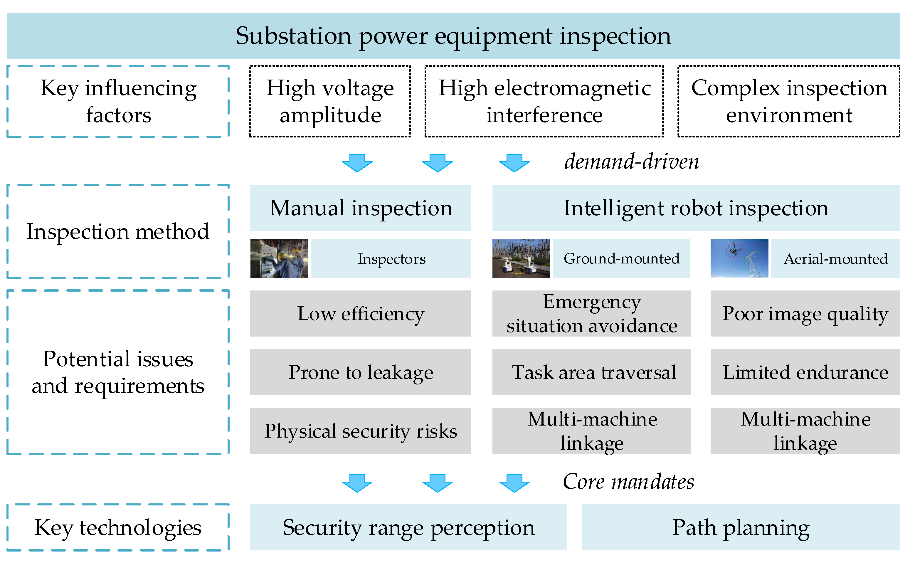
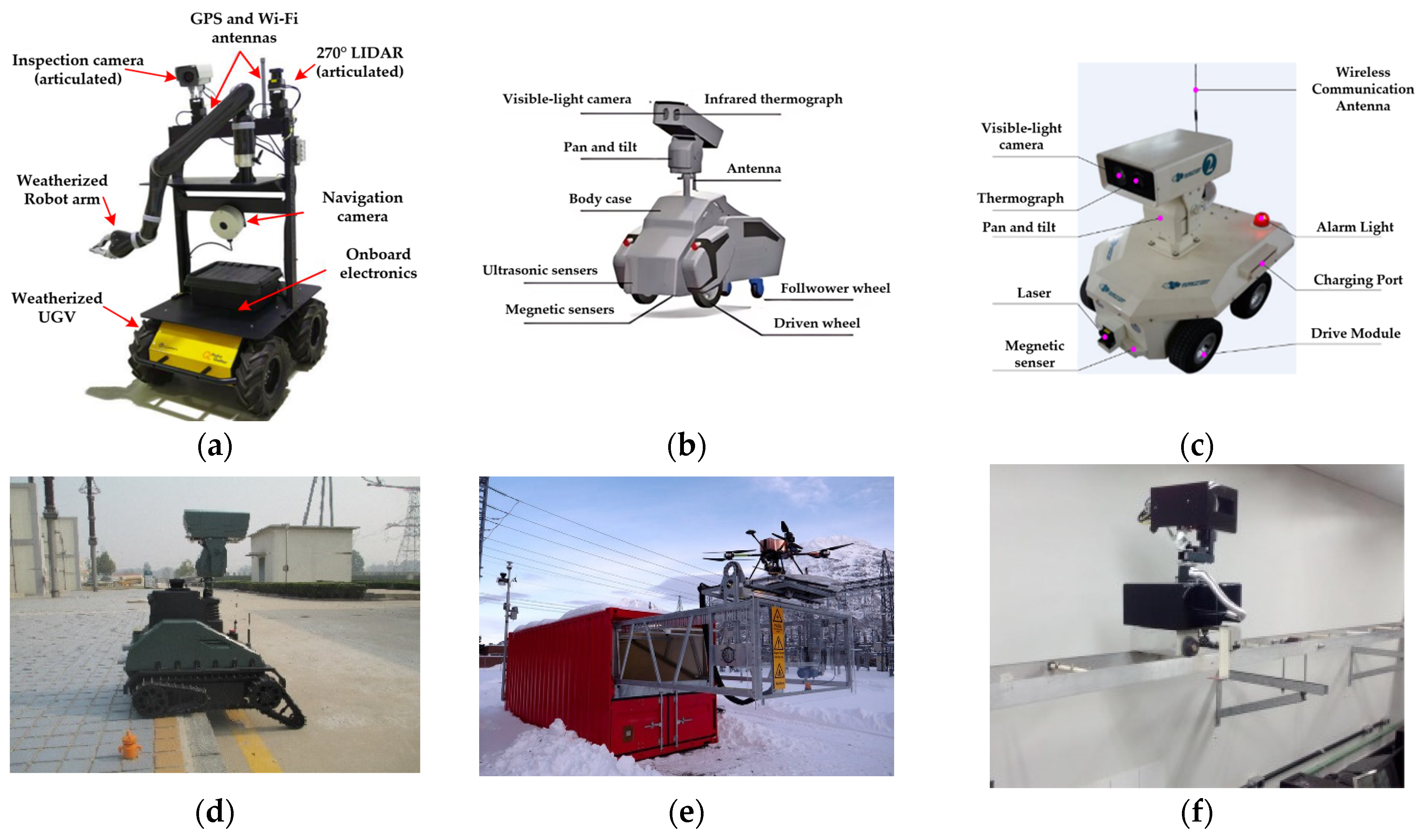

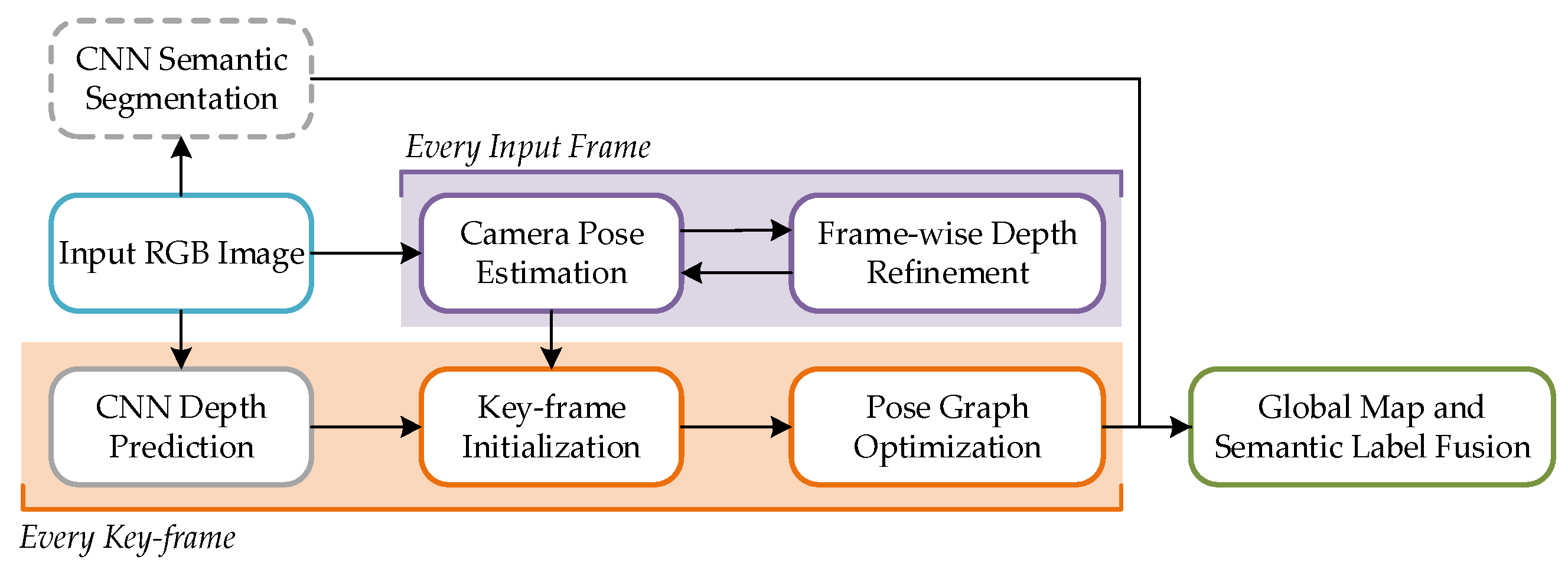
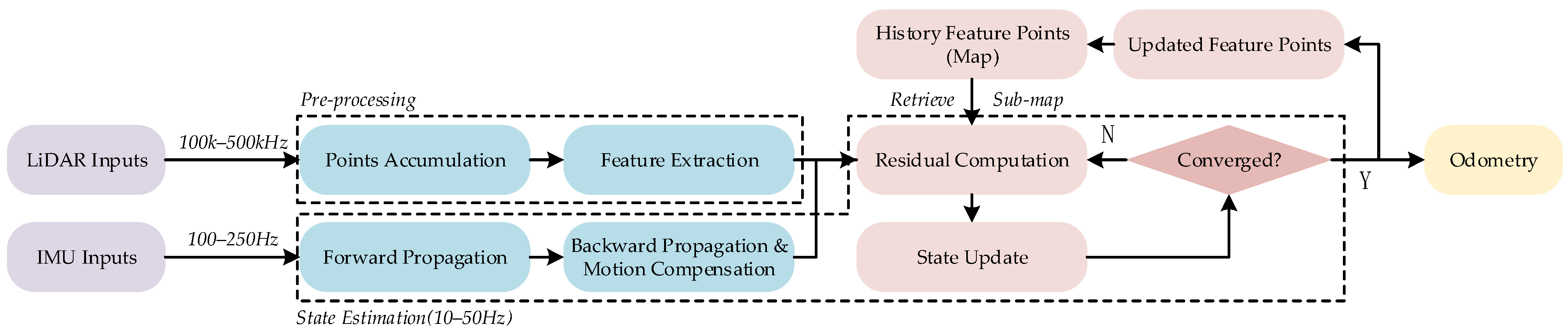
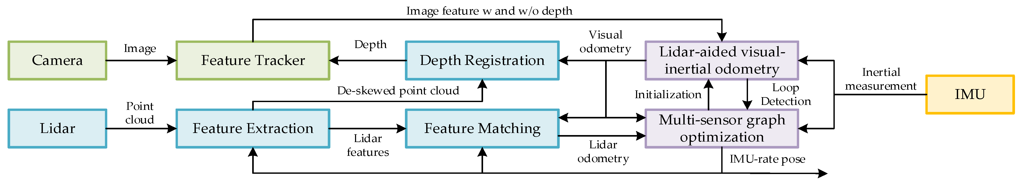
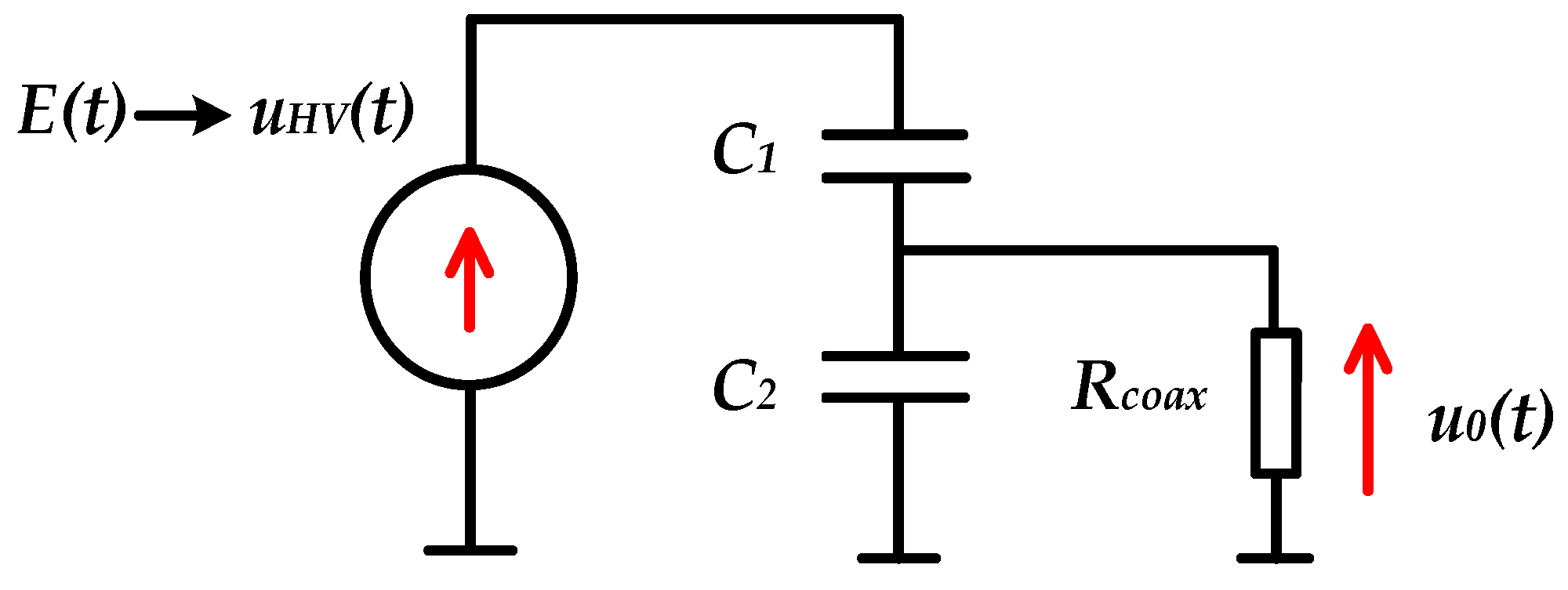
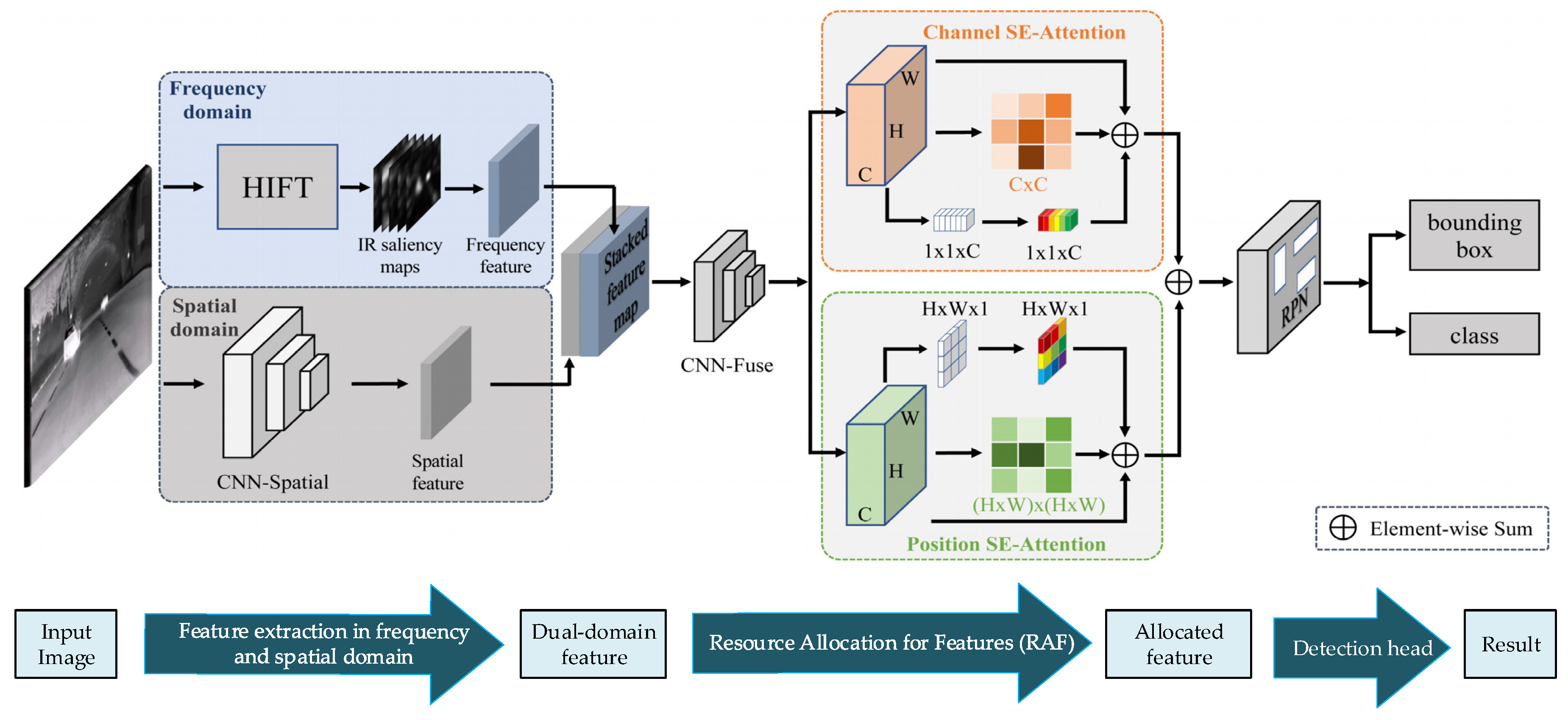
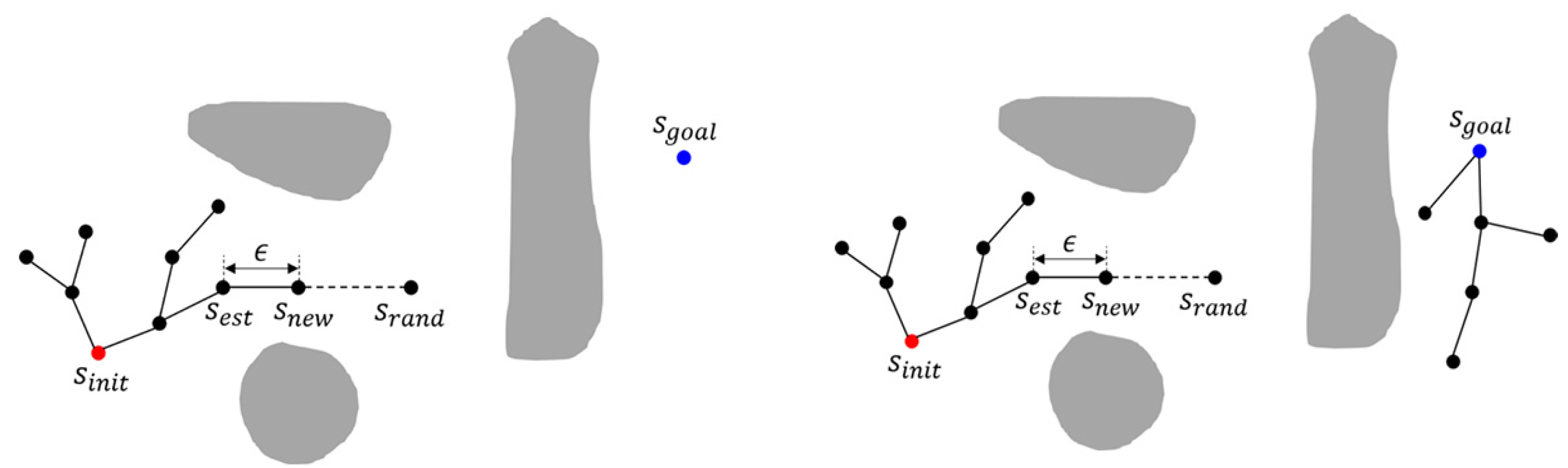
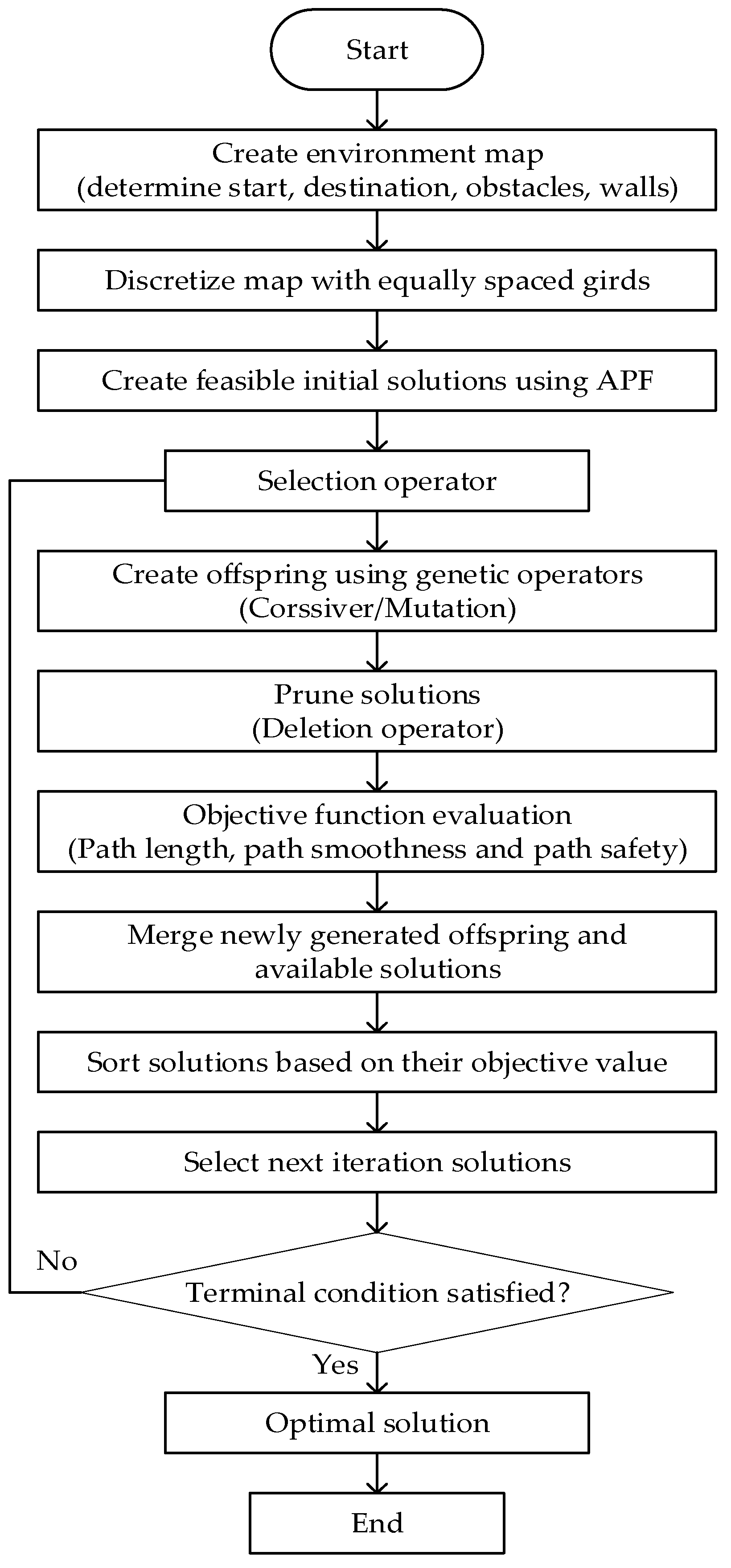
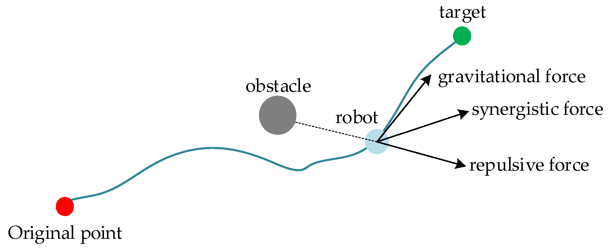
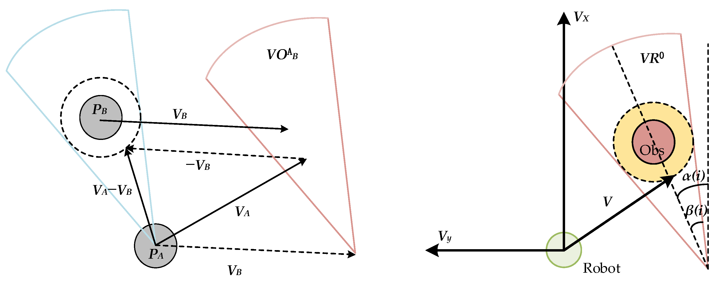
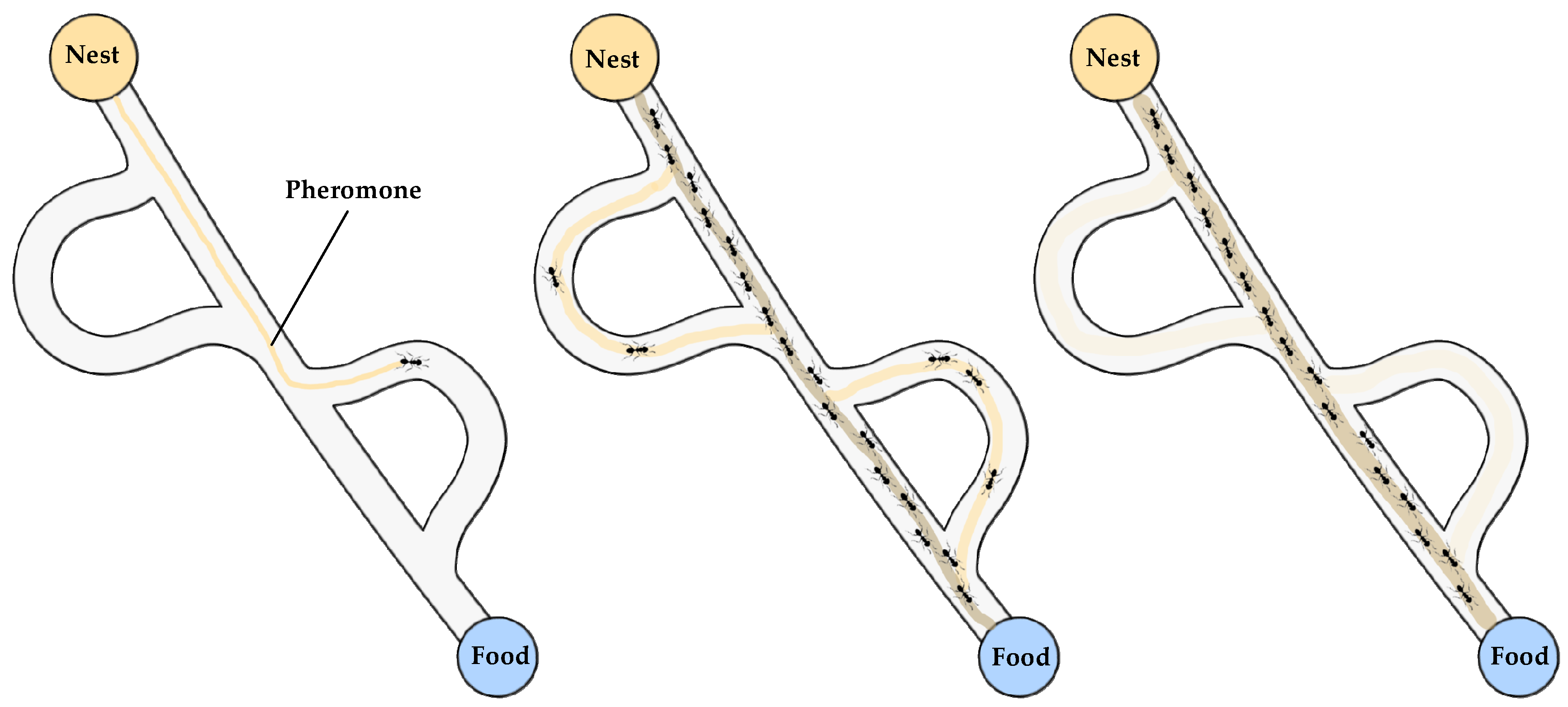
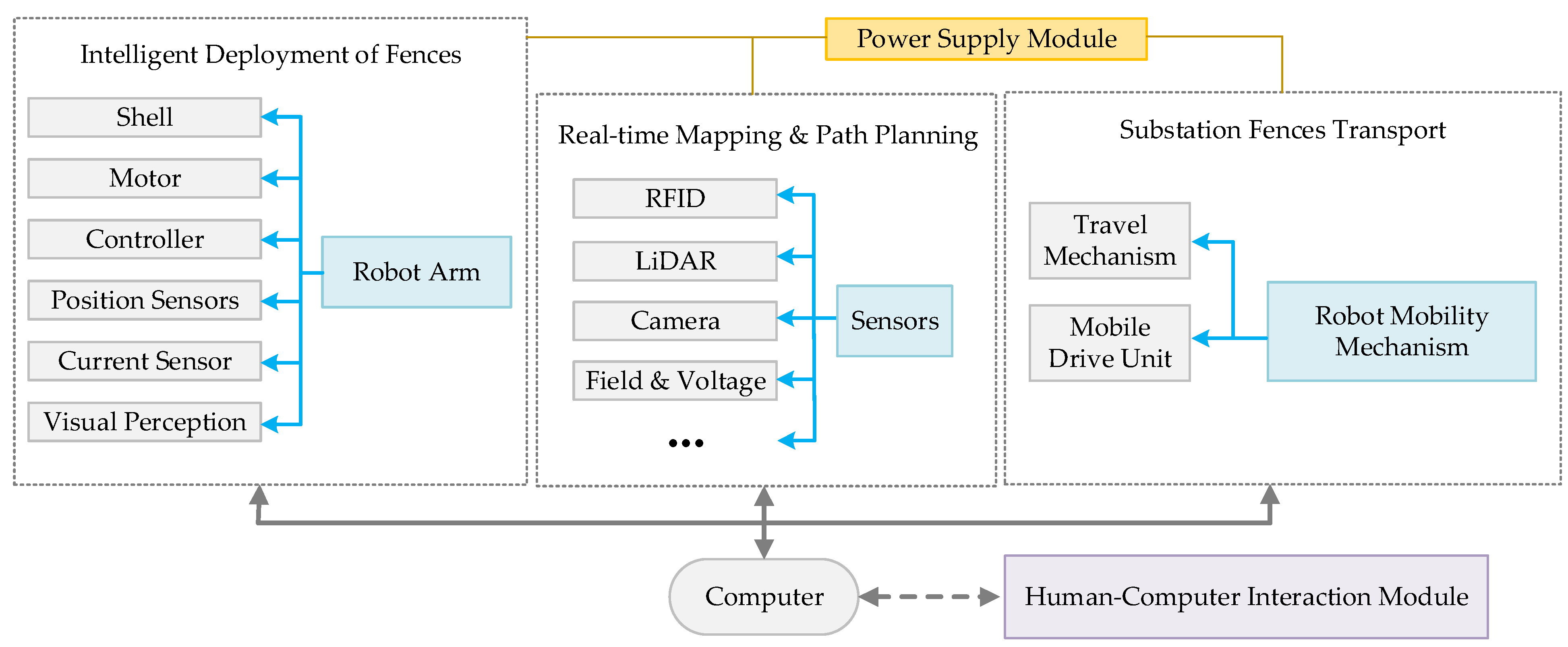


Disclaimer/Publisher’s Note: The statements, opinions and data contained in all publications are solely those of the individual author(s) and contributor(s) and not of MDPI and/or the editor(s). MDPI and/or the editor(s) disclaim responsibility for any injury to people or property resulting from any ideas, methods, instructions or products referred to in the content. |
© 2024 by the authors. Licensee MDPI, Basel, Switzerland. This article is an open access article distributed under the terms and conditions of the Creative Commons Attribution (CC BY) license (https://creativecommons.org/licenses/by/4.0/).