Article

Development of a Series Braking Resistor to Eliminate Control Interference in Multi-Infeed HVDC Systems Considering the AC Three-Phase Fault—An Actual Case Study

1
Department of Electrical and Information Engineering, Seoul National University of Science and Technology, Seoul 01811, Republic of Korea
2
Department of Electrical and Computer Engineering, University of Michigan Dearborn, Dearborn, MI 48128, USA
*
Author to whom correspondence should be addressed.
Energies 2024, 17(16), 4112; https://doi.org/10.3390/en17164112 (registering DOI)
Submission received: 8 July 2024 / Revised: 9 August 2024 / Accepted: 16 August 2024 / Published: 19 August 2024
(This article belongs to the Special Issue Advanced Technologies in Power Quality and Solutions—2nd Edition)

Abstract

:
The integration of converter facilities into power systems has warranted a growing need to address the control interference phenomenon. In this study, we propose a facility-based approach to mitigate the control interference between adjacent high-voltage direct current (HVDC) units in a multi-infeed HVDC system. The proposed method uses a series braking resistor (SeBR) as a preventive measure to restore control when a fault occurs in one HVDC unit within a multi-infeed HVDC system, thereby enabling stable operation of adjacent HVDC units. The developed SeBR model incorporates an inductor component and is divided into Stages 1 and 2 to overcome the frequency reduction issue associated with the long-term deployment of conventional R-based SeBRs. Additionally, if the fault continues to affect the control of adjacent HVDC units despite the application of a blocking stage in the faulted HVDC unit, switch controller logic circuits are designed considering the deployment of Stage 2 of the proposed SeBR. The effectiveness of the proposed SeBR is validated based on the detailed modeling and verification of actual HVDC systems via a case study. The results validate the superior performance of the proposed SeBR over other methods in ensuring a continuous stable operation of the system.

1. Introduction

The increasing global demand for renewable energy and the need for connecting power systems between countries has led to significant growth in converter-based facilities in power grids [1]. Consequently, interactions and interferences such as control and dynamic interactions among converter facilities have increased in power grids. Cases of wind power generation being significantly affected by control interference between wind power converter systems and high-voltage direct current (HVDC) systems have been reported in Xinjiang [2]. To address these issues, several ongoing projects and research efforts have focused on evaluating and preventing control interference in converter facilities [3].
The control interference among converter-based facilities, particularly those caused by faults, has been extensively researched in recent years [4,5,6,7,8,9,10]. In [4], the author discusses the application of fault ride-through (FRT) mechanisms in modular multilevel converter (MMC)-based HVDC systems. This study proposes two FRT mechanisms to prevent HVDC converter stations from disconnecting from the AC grid during certain fault conditions. In [5], the author addresses the issue of overvoltage that can occur at the transmission end converter bus in line-commutated converter (LCC)–HVDC systems during AC faults. The research proposes a coordinated control strategy that leverages hydropower phase control to mitigate overvoltage problems. Another study [6] proposes advanced fault-handling mechanisms that coordinate control strategies, such as increasing the firing angle of LCCs and blocking voltage source converters during faults, to ensure the system can withstand AC and DC faults and recover quickly. However, the aforementioned studies do not primarily address the control interference that can occur between HVDC systems. Additionally, the proposed solutions focus on control strategies rather than equipment-based solutions.
Several studies were also conducted to analyze control interference phenomena between HVDC systems and converter-based facilities when AC grid faults occurred [7,8,9,10]. In [7], a method was discussed to enhance the DC FRT capability of wind farms (WFs) connected to the grid through a bipolar MMC-HVDC. This method uses a coordinated control strategy to minimize the need for the rapid operation of DC breakers, supports the AC grid after faults, ensures balanced power flow, and improves the system’s overall resilience to disturbances. Another study [8] presents an advanced active energy control strategy utilizing MMC sub-module capacitance at converter stations. This strategy is designed to enhance the AC FRT ability of MMC-HVDC systems connected to offshore wind farms (OWFs) by actively absorbing surplus power during grid-side AC faults. In [9], the author introduces a dynamic reactive current optimization strategy to enhance AC FRT capabilities in OWFs connected via MMC-HVDC systems. This strategy focuses on controlling the MMC’s internal sub-module energy to manage excess power during onshore AC faults, thereby stabilizing the system voltage and maintaining grid stability. In [10], the author explores fault current control in an MMC within an HVDC-connected OWF. This paper proposes a coordinated control method to align the phase angle of the MMC with that of the OWF. Previous studies have researched and proposed control strategies to enhance system stability and prevent control interference in systems where a WF and HVDC are combined. However, they did not address control interference between HVDC systems, and the direct application of these control strategies to actual commercial systems remains challenging.
Accordingly, researchers have proposed equipment-based approaches [11,12,13,14]. An equipment-based approach reported in [11] combines control methods to suppress sub-synchronous oscillations (SSOs). Herein, a damping controller that can be integrated with the control loop of a battery energy storage system was presented as a means to mitigate SSOs; its effectiveness was verified using simulations. Additionally, [12] also proposes an adaptive robust control method for battery storage systems to suppress power oscillations and ensure stable grid operation to address SSO issues in OWFs connected to the grid via MMC-HVDC systems. Another study [13] analyzes the harmonic instability issues in a practical HVDC system with fixed series compensation and a static synchronous compensator (STATCOM) and proposes solutions to address them. The study suggests bypassing series capacitors as a temporary solution, which was validated through field tests. In [14], the study addresses the issue of sub-synchronous resonance (SSR) in WFs connected to LCC-HVDC systems. It proposes a wideband harmonic voltage feedforward control strategy using a STATCOM to suppress SSR without needing to know the specific oscillation frequency. Although the aforementioned studies report equipment-based solutions, their scope is limited to a single HVDC unit or a WF integrated with HVDC, and they do not address the interference phenomena occurring between HVDC systems. Additionally, these studies do not deal with control interference caused by faults but rather propose methods to suppress SSOs or SSR and mitigate resonance.
Control interference issues can occur not only between WF and WF-coupled HVDC systems but also among different HVDC systems. In particular, control interference issues between HVDC systems have been identified in Jeju Island, South Korea, where HVDC units #1 and #2 are installed and operated in proximity [15,16]. In such cases, a fault can occur within an HVDC unit, leading to the application of a blocking stage and a cessation of operations. However, despite the application of a blocking stage, the impact of the fault may persist in areas with a weak AC grid, such as Jeju Island. This can potentially affect the control of adjacent HVDC systems; non-restoration of control may lead to widespread power outages.
Based on the aforementioned reports and findings, we propose a practical solution to address the control interference issues between HVDC systems in a multi-infeed HVDC system. The method proposed in this paper includes deploying a series braking resistor (SeBR) facility to prevent the impact of faults occurring in one HVDC system on the operation of adjacent HVDC systems. The SeBR is modeled and designed for long-term deployment with Stage 1 and Stage 2 based on frequency detection. The subsequent controller logic is also designed suitably. The proposed SeBR is validated by modeling the HVDC systems of Jeju Island and mainland South Korea, where two HVDC systems operate in proximity. The results demonstrate that the proposed SeBR ensures the stable operation of South Korea’s HVDC systems. The contributions of this study can be summarized as follows.
  • Ours is the first study to propose a facility-based approach to suppress the effects of control interference caused by a fault in a single HVDC unit within a multi-infeed HVDC system on the control of adjacent HVDC systems.
  • The proposed method ensures that adjacent HVDC systems operate stably even when a fault occurs in a single HVDC unit within a multi-infeed HVDC system. The developed SeBR is used for rapid voltage recovery at the fault bus to prevent the propagation of the fault, particularly in weak AC grids.
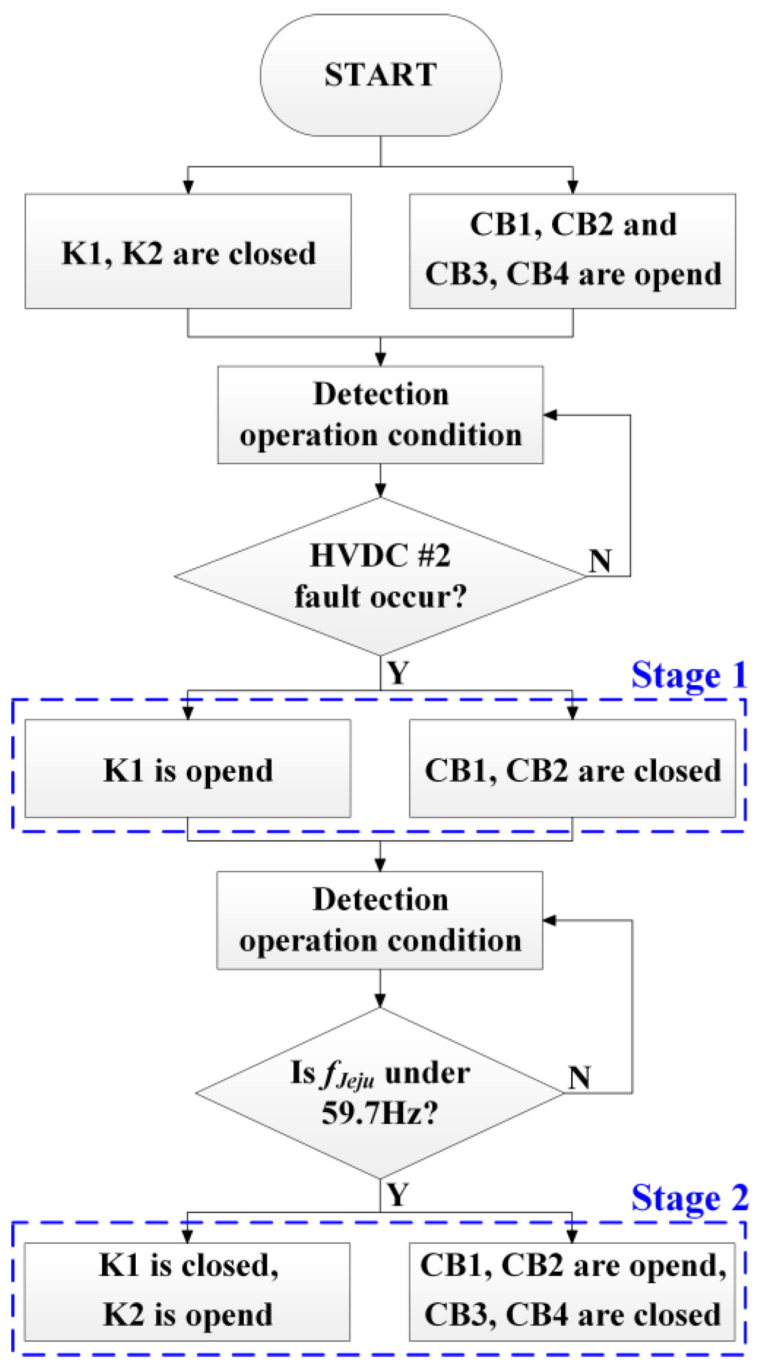
  • We also considered scenarios where converter blocking is applied to address the fault occurring in a single HVDC unit yet the impact of the fault continues to affect the control of adjacent HVDC systems. To address this, we modeled the SeBR with long-term application considerations by dividing it into Stage 1 and Stage 2, which are activated based on frequency detection.
  • The effectiveness of the proposed SeBR is validated via detailed modeling and verification of the HVDC systems of Jeju Island and the mainland in South Korea, where two adjacent HVDC units are currently operational.

2. System Configuration

Figure 1 depicts a simplified schematic of the proposed facility to be installed on Jeju Island in Korea and the mainland system. The grid of Jeju Island and the main grid of Korea are connected by two LCC-based HVDCs in a multi-infeed configuration. In the Jeju grid, the electrical distance between the two HVDC systems is notably close. The short circuit ratio (SCR) for the Jeju grid is approximately 4, characterizing it as a weak AC grid [17]. This condition contributes to the frequent occurrence of AC disturbances within the Jeju system [18,19]. In particular, the most critical three-phase fault can precipitate failure in an HVDC system. This failure can potentially affect adjacent HVDC systems that are proximally located in terms of electrical distance [20].
Three-phase faults are less likely to occur compared to single-phase faults [21]. However, three-phase faults do occur and can lead to severe situations. For example, the initial cause of the 2016 South Australian blackout was reported to be a three-phase fault on the Hummocks–Snowtown–Bungama 132 kV transmission line. This blackout incident was caused by storm damage and resulted in significant disruption and damage [22]. Furthermore, a study [23] analyzed a real-world three-phase fault that occurred at the 220 kV bus in Padghe, India. In particular, the AC grid of Jeju Island, as discussed in this paper, is classified as a weak AC grid due to geographical limitations. The HVDC systems on Jeju Island are utilized like a synchronous generator within the Jeju power system, making significant contributions to the total power production and serving as an intermittent backup source [24]. Due to unpredictable natural events and critical geographical constraints, we require facilities that can prevent and prepare for three-phase faults.
In this study, we examined the multi-infeed HVDC systems of Korea based on the detailed modeling of the Jeju HVDC #1 and #2. The mainland network is structured around the interconnection buses associated with the Jeju HVDC #1 and #2, namely, Haenam and Jindo-Bus, respectively, and includes four additional buses. Each bus comprises a load, with two of the buses additionally comprising synchronous generators rated at 150 and 200 MVA. The Jeju Island system comprises three buses with loads connected to the Jeju HVDC #1 (Jeju Bus) and #2 (Jeju Bus2). A synchronous generator with a capacity of 100 MVA is connected to one of these buses.
The weak Jeju grid hosts two LCC-based HVDC systems that absorb reactive power, which can result in voltage stability issues induced by reactive power deficits [25]. To address this, a synchronous condenser (SC) and STATCOM with capacities of 70 and 50 VAR, respectively, have been installed and are operational in proximity to the HVDC systems within the Jeju system [26,27].
The proposed SeBR can be installed in both the Jeju HVDC #1 and #2. It is located between the converter transformer and AC bus within the HVDC converter station to cater to the frequent occurrence of faults at the converter transformer [28], particularly the severe three-phase faults, which the SeBR can effectively mitigate.
The proposed SeBR is configured in two stages. In Stage 1, a conventional SeBR is designed to limit substantial fault currents at the outset by employing resistor R1 with a high resistance for bus voltage restoration. Stage 2 introduces an additional SeBR comprising L1 and R2. This configuration aims to prevent frequency reductions in the Jeju system that could originate from the extended activation of Stage 1. The operational algorithm of the SeBR encompassing both stages is described in Section 3.
It is important to note that the Jeju AC grid is geographically isolated, which makes the expansion of synchronous generators challenging due to terrain constraints. Therefore, the two Jeju HVDC systems play the role of generators by transferring active power from the mainland. Given these conditions, the Jeju AC grid has been identified as a weak AC grid with an SCR of 4.0, making the control interference issues discussed in this study inevitable. For example, research indicated in [29,30] suggests that weak AC grids are more susceptible to transient instabilities, which can more easily lead to system instability. Additionally, references [31,32,33,34,35] highlight that considerable research is ongoing due to concerns over the stability of converter facilities in weak AC grids. In conclusion, system instability issues can easily arise in the Jeju grid due to its status as a weak AC grid, and the control interference problem that we are concerned about in this study can also occur readily. This has led us to research and develop facility-based methodologies applicable across various system conditions, which is the focus of this study.

3. Modeling of the Jeju HVDC System

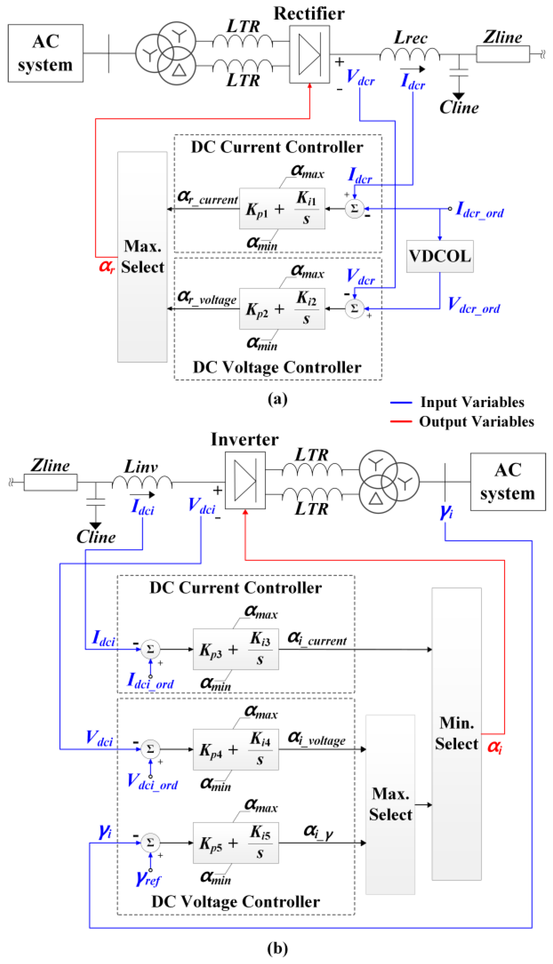
3.1. Normal Operation of the Jeju HVDC #1 and #2

The HVDC system models the actual operation of the Korean Jeju HVDC #1 and #2. The rated voltages of the Jeju HVDC #1 and #2 are 180 and 250 kV, and the corresponding rated outputs are 100 and 200 MW, respectively [36]. The two-level converters were modeled as two-level using thyristor valves, and the DC line was configured as a bipole. In the Jeju HVDC #1 and #2, half of the rated power flows through each pole such that the rated power can be transmitted through the other pole even if one pole fails [37]. The Jeju HVDC systems feature several control modes, including frequency, power, loop, current, voltage, and firing angle controls [38]. In this study, it is assumed that the Jeju HVDC system operates in a normal state even before a fault occurs, making normal operation modeling essential. Particularly in a multi-infeed HVDC system, it is necessary to ensure that other HVDC systems not affected by the fault can continue to operate normally after the fault. Therefore, we focus on modeling the most commonly used controls, namely, the current, voltage, and firing angle, as detailed in [39].
Figure 2 illustrates the control mode selection scheme used for the Jeju HVDC #1 and #2. It depicts the control sequence for the rectifier and inverter of the Jeju HVDC system shown in Figure 1. The parameters for each the Jeju HVDC system are the same as those in Figure 1, and both the Jeju HVDC #1 and #2 modeled in this paper select their control modes using the control method presented in Figure 2. And both the rectifier and inverter are equipped with DC voltage and DC control modes. Additionally, the rectifier incorporates a voltage-dependent current-order limiter (VDCOL) [40]. The rectifier and inverter select different control modes depending on the operating conditions of the Jeju HVDC system. For instance, under normal operating conditions where the rectifier controls the DC voltage, Vdcr = 1.0 p.u. and Idcr = 0.5 p.u. According to the characteristic voltage–current (V–I) curve of the Jeju HVDC systems [41], the reference values for the DC voltage and current of the rectifier are Vdcr_ord = 1.0 p.u. and Idcr_ord = 1.3 p.u. In this case, αr_voltage from the DC voltage controller in Figure 2a is an output similar to the present αr value, and the DC current controller reduces αr_current to adjust the present value of Idcr from 0.5 p.u. to the reference value (1.3 p.u.). Therefore, as αr_voltage is greater than αr_current, the rectifier selects the value of αr_voltage from the DC voltage controller as the αr value using the Max Select function.
Conversely, the output αi_current from the DC controller in Figure 2b is similar to the present αi value in the case of the inverter, whereas the DC voltage controller increases the value of αi_voltage to adjust Vdci to match the value of Vdci_ord. Therefore, the output from the DC controller is typically selected in the Min Select function on the inverter side (Figure 2b).
Typically, the rectifier controls the DC current and the inverter controls the DC voltage in HVDC systems. However, the rectifier controls the DC voltage and the inverter controls the DC current in the case of the Jeju HVDC #1 and #2. This configuration was strategically implemented to rapidly modulate the DC power transmitted from the main grid by controlling the DC current within the weak Jeju grid, representing a distinctive characteristic of the Jeju HVDC systems [39].

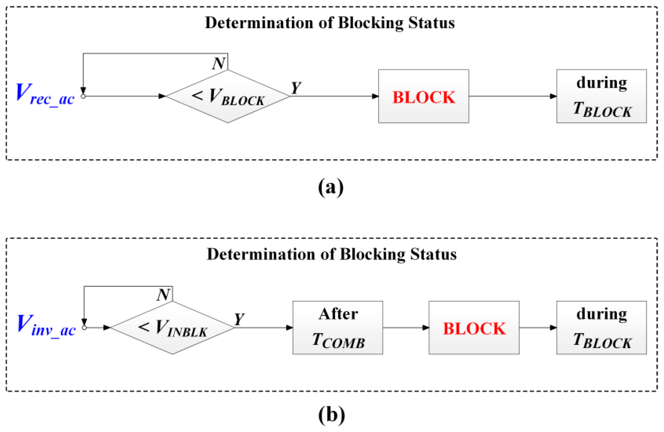
3.2. Converter Blocking Scheme of the Jeju HVDC #1 and #2

When a fault occurs in the HVDC system or the adjacent AC system, a blocking scheme is activated to protect the HVDC system [41]. Figure 3 illustrates the converter blocking scheme of the Jeju HVDC #1 and #2 when a fault occurs in the AC system. Table 1 summarizes the definitions of each variable [42,43]. Based on [42], the operation of the Jeju HVDC block (Figure 3) was modeled with a focus on the protection mechanisms of the converter against AC faults. Consequently, operations related to internal incidents, such as bypass actions, were omitted. The blocking operation of the Jeju HVDC systems is triggered by the AC voltages of the rectifier and inverter. As indicated in Figure 3a, a converter blocking operation is initiated when the AC voltage at the rectifier side decreases below the threshold value (VBLOCK), sustaining the blocking state for the duration of TBLOCK. Figure 3b illustrates the blocking scheme at the rectifier following the communication time delay (TCOMB), with the blocking state maintained for the duration of TBLOCK.

4. Proposed SeBR

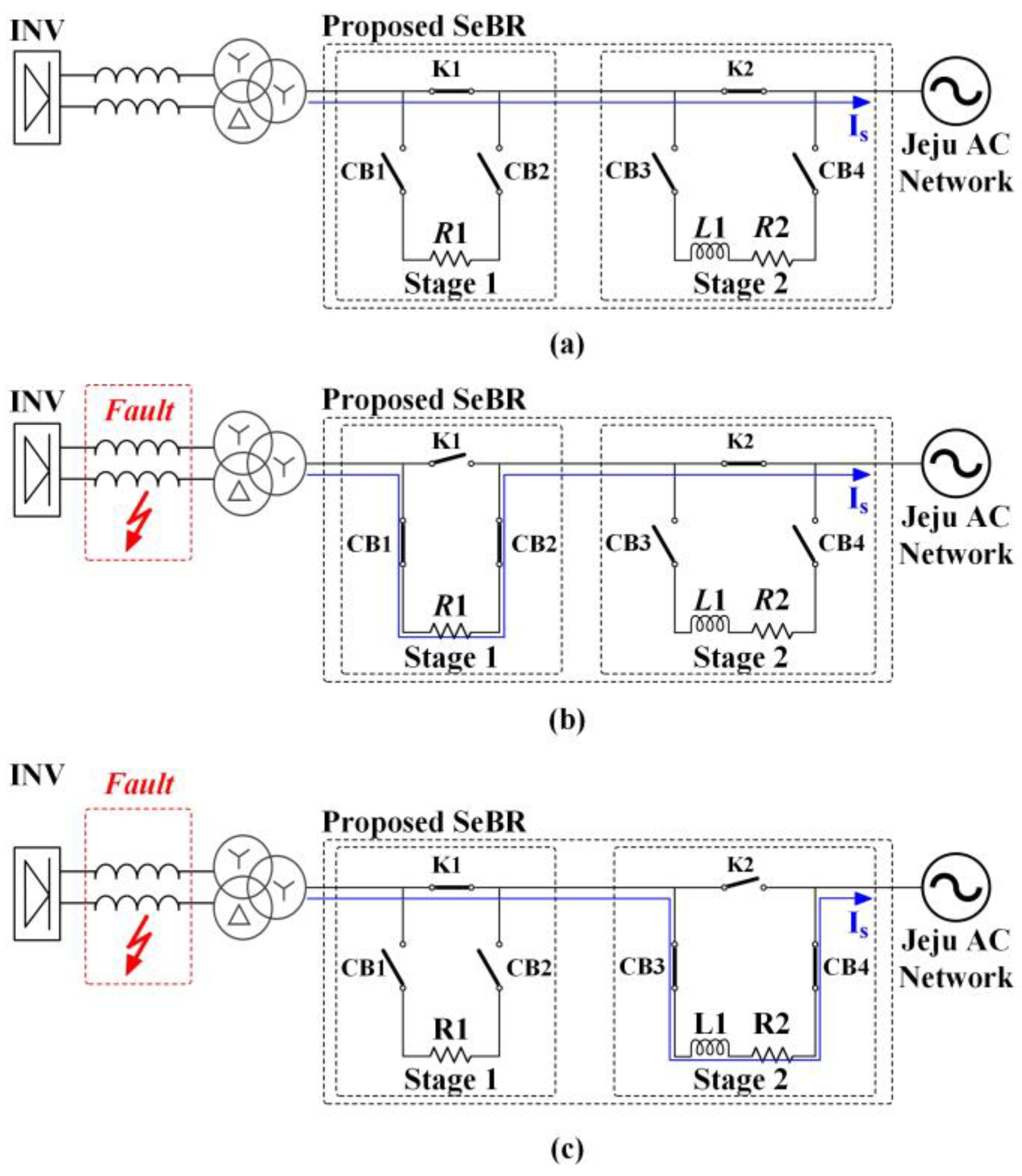
4.1. Configuration and Workflow of the Proposed SeBR

Figure 4 depicts the modeling and operational scheme of the proposed SeBR, which is structured into two stages. The first stage comprises resistor R1, which is similar to conventional SeBR configurations. In general, SeBRs maintain continuous connectivity within a system. However, to mitigate the risks associated with potential resistor damage that can interrupt the operation, a switch has been incorporated to facilitate R1 disconnection even under normal operating conditions [44]. In this study, we specifically address scenarios within the Jeju grid, which is interconnected with multi-infeed HVDC systems. A sustained SeBR activation is recommended during AC faults to ensure system stability, even when one HVDC unit is blocked and the other fails to be appropriately controlled. However, conventional SeBR configurations, such as Stage 1, which are characterized by high-resistance values, can lead to substantial power consumption when operated over long durations, thereby impacting the system frequency. Consequently, the proposed SeBR incorporates an additional Stage 2 equipped with resistor R2 (with a lower resistance value than R1) and inductor L1. In the event of a three-phase fault within the Jeju grid, the design of the proposed SeBR ensures that Stage 1 is activated followed by Stage 2 based on the specific conditions prevailing in the Jeju system.
Figure 4a illustrates the operational schematic of the proposed SeBR under normal conditions. In this configuration, switches K1 and K2 remain closed, whereas circuit breakers CB1, CB2, CB3, and CB4 are opened to prevent faults during operation. Consequently, current flows through K1 and K2 without interruption. Figure 4b depicts the operational schematic of Stage 1 immediately after the occurrence of a fault in the AC system between the HVDC converter and transformer. In this case, K1 opens and CB1 and CB2 remain closed, introducing R1 into the system. The rapid engagement of R1 facilitates the restoration of bus voltage on the inverter side and reduces the fault current entering the Jeju grid. Despite the HVDC initiating a blocking operation, if control over an adjacent HVDC remains unrecovered and the power supply to the Jeju system via the HVDC is reduced, the frequency of the Jeju system may decrease. As indicated in Figure 4c, the proposed SeBR closes K1 and opens CB1 and CB2 to disconnect Stage 1 from the system. Simultaneously, K2 is opened and CB3 and CB4 are closed to activate Stage 2, introducing R2 and L1 into the system to stabilize the frequency and maintain the effectiveness of the SeBR. Because Stage 2 includes an inductor component L1, R2 is maintained significantly lower than R1 to prevent system overload during prolonged operations.
Figure 5 illustrates the operational strategy of the proposed SeBR. The transition from Stage 1 to Stage 2 is contingent on the frequency of the Jeju system. In accordance with the operational guidelines of the Jeju system [45], a shift from Stage 1 to Stage 2 is initiated when the frequency reduces below 59.7 Hz.

4.2. The Necessity of the Inductor Element in the Proposed SeBR

As examined in Section 4.1, the configuration and workflow of the proposed SeBR were analyzed in detail. The configuration of Stage 2 of the proposed SeBR includes an R2 component with a smaller value than R1 of Stage 1, connected in series with an L1 component. This paper proposes an SeBR facility to prevent control interference among HVDC systems within a multi-infeed HVDC system, specifically targeting the Jeju grid in South Korea. Note that various situations can occur in the Jeju grid, including an increase in reactive power consumption within the grid. In such situations, not only the HVDC but also the STATCOM and SC of the Jeju grid supply reactive power to the grid load. However, under these conditions, if a fault occurs between the converter station and transformer of the Jeju HVDC #2, a large amount of reactive power flows into the faulted area of the Jeju HVDC #2.
Figure 6 shows the reactive power flow and PCC voltage of the Jeju HVDC #2. In Figure 6a, the results of the conventional 1 method (Conv 1) show that a large amount of reactive power flows into the faulted Jeju HVDC #2. Additionally, in Figure 6b, the results of the conventional 1 method indicate that the PCC voltage of the Jeju HVDC #2 in the Jeju grid does not recover after the fault. To recover the voltage at the PCC point after the fault and prevent unstable reactive power flow, the SeBR facility was deployed and the results were observed. Note that the proposed method and the conventional 2 method (Conv 2) were compared under the same conditions to compare the differences between the proposed SeBR and the conventional SeBR.
In Figure 6a, there is a clear difference between the proposed method and the conventional 2 method. Specifically, the proposed method, which includes an inductor (L1 component), shows a consumption of a certain amount of reactive power after Stage 1 is terminated at 1.6 s and Stage 2 is deployed. On the other hand, the conventional 2 method, which lacks an inductor and continuously deploys only Stage 1, shows a partial blockage of reactive power inflow to the fault location. Figure 6b shows the voltage at the PCC point. Immediately after the fault, there is no difference between the proposed method and the conventional 2 method. The proposed method terminates Stage 1 and deploys Stage 2 at 1.6 s. However, upon closer inspection of the conventional 2 method graph, it is observed that control is not maintained, resulting in continuous voltage fluctuations, while the proposed method recovers the voltage to 0.96 p.u. (top right part in Figure 6b).
The results shown in Figure 6 indicate that if a fault occurs while reactive power supply is needed within the Jeju grid, it can lead to overall system instability. In this situation, deploying a conventional SeBR facility, composed only of Stage 1 with R1, as in the conventional 2 method, failed to prevent control interference and could not prevent overall system instability. However, when the proposed method, which includes Stage 2 composed of R2 and L1, was deployed, it was able to recover the voltage to 0.96 p.u. and consume a significant amount of reactive power through the L1 component. This prevented control interference with the Jeju HVDC #1, which was not affected by the fault, and helped restore the stability of the entire grid.

5. Case Studies and Simulation Results

5.1. Test System and Simulation Conditions

The proposed SeBR was validated by modeling the actual mainland and Jeju systems of South Korea as the test system. The proposed SeBR was positioned between the converter station and the transformer of the Jeju HVDC #2 in the test system to prevent instability in the control of the Jeju HVDC #1 when a fault occurs at the Jeju HVDC #2. Table 2 summarizes the parameters of the actual Jeju HVDC systems, Jeju grid, and mainland grid in the test system. The parameters of the proposed SeBR can be determined using trial-and-error methods.
A three-phase ground fault was assumed to occur between the converter transformer and converter AC bus of the Jeju HVDC #2 in the test system. The triggering of a blocking operation in the Jeju HVDC #2 decreased the transmission of active power from the mainland system to the Jeju system. Therefore, to ensure a stable power supply in the Jeju system, the Jeju HVDC #1 transmitted maximum power during the blocking operation of the Jeju HVDC #2. Additionally, the generators in the Jeju grid increased their output. In particular, the three-phase ground fault occurred at 1.2 s and lasted for 0.1 s. The Jeju HVDC #2 blocking operation was applied after 0.05 s of fault occurrence, and the Pord value of the Jeju HVDC #1 was simultaneously increased from 100 MW to 150 MW. Consequently, the generators in the Jeju system increased their output from 50 MW to 100 MW.
The simulation compared the results of three different cases, wherein the blocking operation of the Jeju HVDC #2 and the output increase in the Jeju HVDC #1 were applied at the time of fault occurrence. The simulations were performed using PSCAD software (v4.2).
In this study, “Prop” refers to the method implementing the proposed SeBR, the conventional 2 (Conv 2) method involves the operation of a conventional SeBR and is applied to only Stage 1 in the proposed SeBR, and the conventional 1 (Conv 1) indicates the method where only the blocking operation of the Jeju HVDC #2 and the output increase in the Jeju HVDC #1 are applied without considering the SeBR.
A comparison of the proposed method with conventional methods confirmed that the activation of Stage 1 in the proposed SeBR facilitated the recovery of the system voltage and control of the Jeju HVDC #1 after the occurrence of a fault of the Jeju HVDC #2. Additionally, the comparison of the proposed and conventional 2 methods indicated that the activation of Stage 2 in the proposed SeBR not only helps in controlling the Jeju HVDC #1 but also aids in recovering the system frequency in the Jeju Island grid. Table 3 summarizes the specific applications for each case.

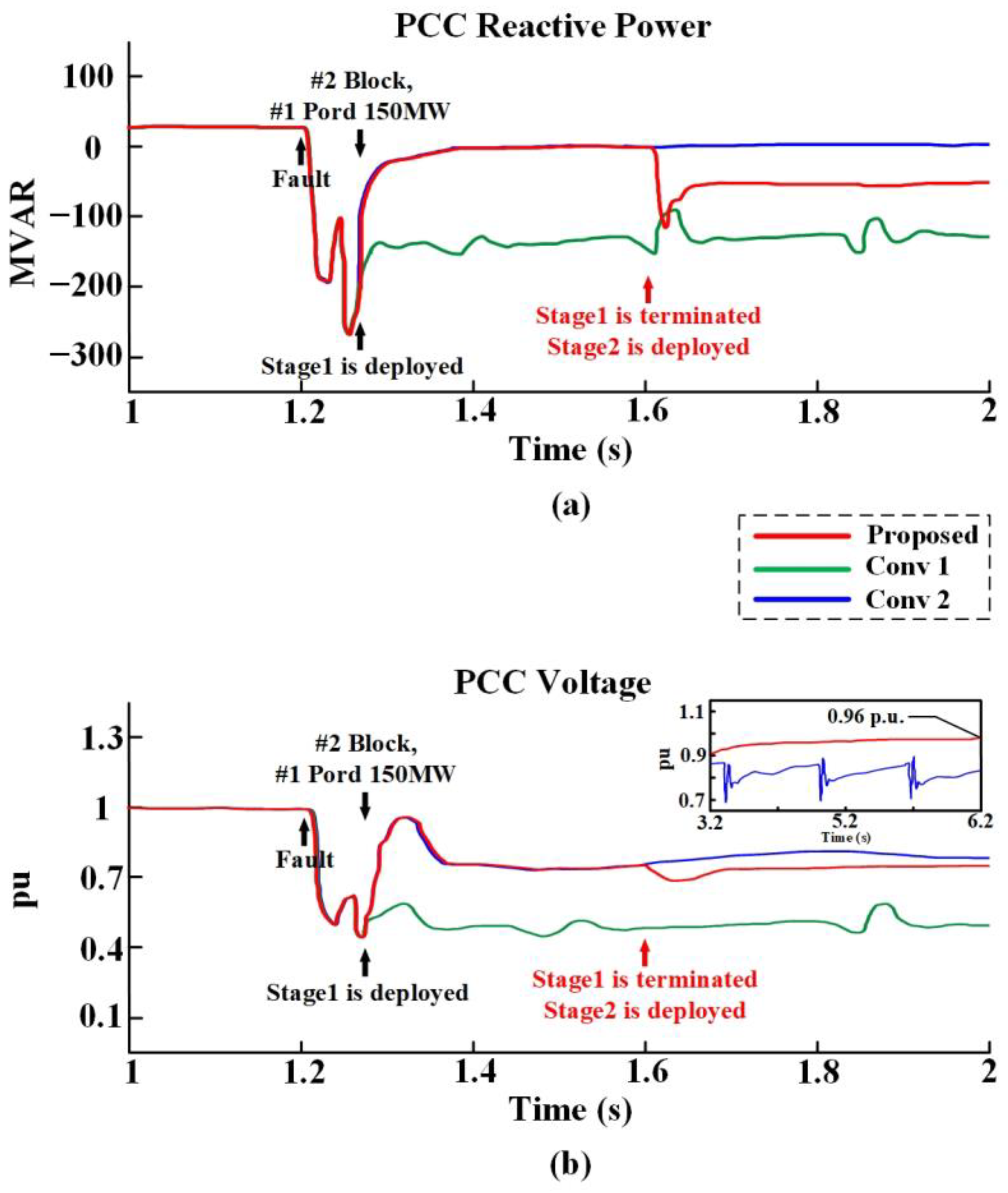
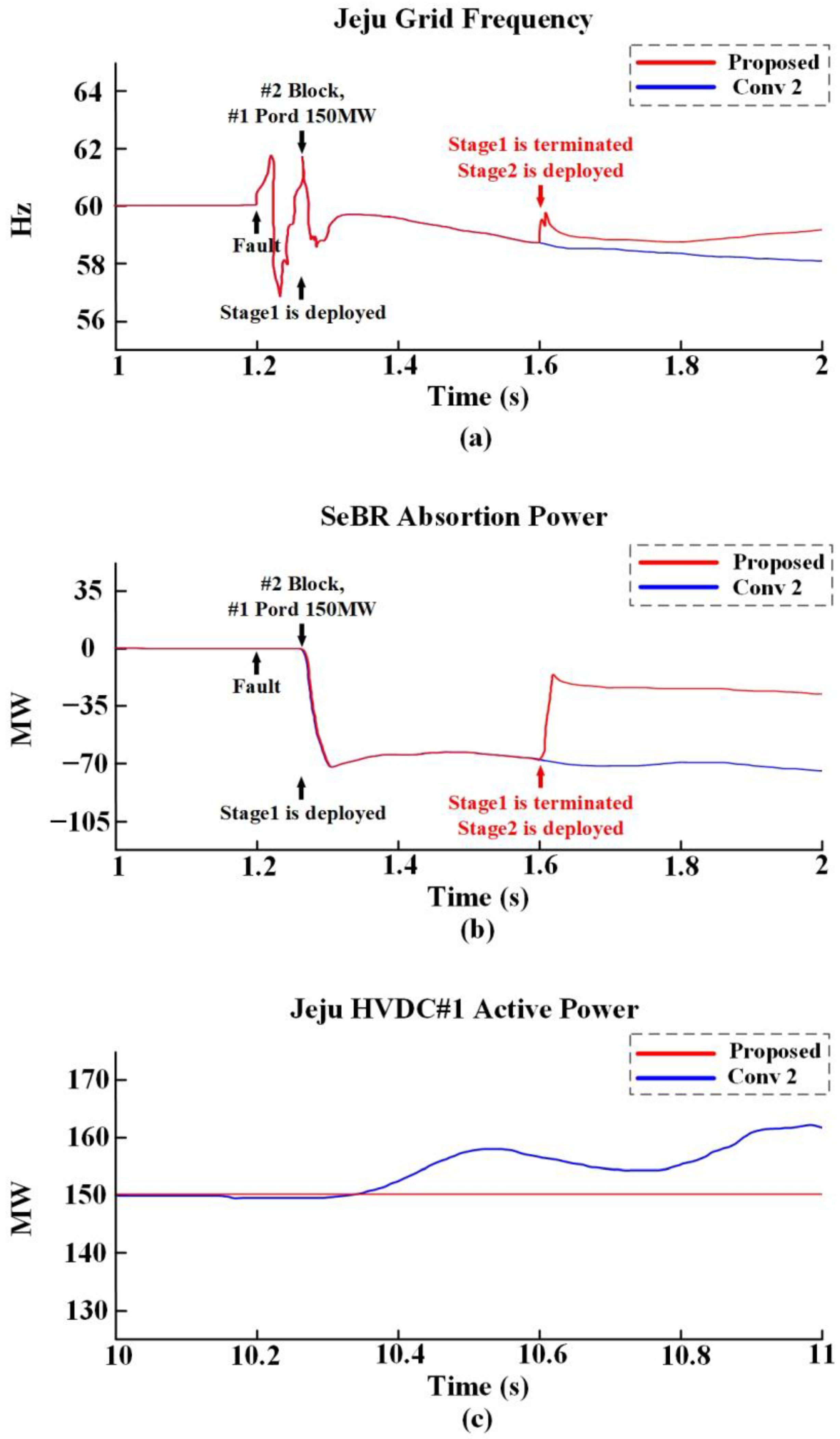
5.2. Verification of the SeBR

Figure 7 depicts the simulation results of all methods, wherein the proposed and conventional 2 methods implement the SeBR. In contrast to the conventional 1 method, both the proposed and conventional 2 methods demonstrate a recovery in the bus voltage on the inverter side of the Jeju HVDC #1 following the deployment of Stage 1 after the occurrence of a fault in the Jeju HVDC #2 (Figure 7a). Furthermore, both the proposed and conventional 2 methods exhibit a gradual recovery of voltage, which stabilizes at 0.95 p.u. and 2.6 s after the fault occurrence. Subsequently, the proposed method recovers further to 0.99 p.u. after 8.35 s (top right part in Figure 7a), ensuring the stable operation of the Jeju HVDC #1; the conventional 2 method exhibits a voltage of 0.925 p.u. at the same time. In Figure 7b, both the proposed and conventional 2 methods indicate that the control of the Jeju HVDC #1 operates normally after the deployment of Stage 1. The fault occurring in the Jeju HVDC #2 is blocked at 1.25 s, leading to a simultaneous change in the command value (Pord) of the Jeju HVDC #1 from 100 MW to 150 MW at 1.25 s, resulting in an increasing trend. The findings obtained from the proposed and conventional 2 methods indicate that the deployment of SeBR can effectively mitigate disturbances in the control of bus voltage and power transmission at the inverter side of the Jeju HVDC #1, particularly when a three-phase ground fault occurs at the converter station and transformer of the Jeju HVDC #2.
After the occurrence of a fault at the Jeju HVDC #2, the system frequency is detected and switching actions are implemented to terminate Stage 1 and deploy Stage 2 in the proposed method, thereby maintaining stable control over the Jeju HVDC #1. This demonstrates the effectiveness of the proposed SeBR. However, validating this function based on the results depicted in Figure 7a,b is difficult. Because Stage 2 is deployed at 1.6 s in Figure 7a,b, the effects of the proposed SeBR must be validated by comparing the proposed and conventional 2 methods after 1.6 s.

5.3. Verification of the Proposed SeBR

Figure 8 depicts a graphical comparison of the results of conventional 2 and the proposed methods; while a conventional SeBR is continuously deployed in the former, the latter employs a two-stage SeBR.
The results in Figure 7 indicate that both the proposed and conventional 2 methods demonstrate the recovery of inverter side bus voltage and the stable restoration of control in the Jeju HVDC #1 by deploying Stage 1 at 1.25 s along with the implementation of a common solution after the occurrence of a fault in the Jeju HVDC #2.
As the Jeju HVDC #2 continuously maintains the blocking stage, the SeBR must also remain deployed in the system. However, the conventional 2 method does not deploy Stage 2 and continuously deploys the existing Stage 1 with a high-resistance value. This causes the SeBR to act as a load, resulting in a mismatch between power supply and demand in the Jeju Island grid. As explained in Section 2, the synchronous generators in the Jeju grid are subject to maximum output limitations and cannot support the power demands of the SeBR, resulting in frequency reductions and impacting the operation of the Jeju HVDC #1. The proposed method implements a strategy where if the system frequency reduces below 59.7 Hz, a switching operation is initiated to terminate the existing Stage 1 and transition to Stage 2, which includes an inductor component.
Figure 8a depicts the frequency changes in the Jeju Island grid. At 1.2 s, a fault occurs at the Jeju HVDC #2, and at 1.25 s, both the proposed and conventional 2 methods deploy Stage 1. Subsequently, both methods exhibit a gradual decrease in frequency. At 1.6 s, the proposed method detects the frequency drop, terminates Stage 1, and deploys Stage 2, resulting in the recovery of the frequency. After deploying Stage 2, the proposed method restores the frequency to 60 Hz within 1.51 s and maintains a stable frequency range thereafter, ensuring the stable operation of the Jeju HVDC #1.
Figure 8b illustrates a graph of the power consumed by the SeBR. As the conventional 2 method does not implement additional actions, the SeBR continuously consumes a significant amount of power and acts as a high load, leading to power imbalances. By contrast, in the proposed method, the power consumed by the SeBR is reduced by more than half after deploying Stage 2 at 1.6 s upon detecting the frequency drop.
Figure 8c depicts the power output of the Jeju HVDC #1 after 10 s of continuous SeBR deployment. After the occurrence of a fault, continuous SeBR deployment in the conventional 2 method reduces the frequency, which subsequently impacts the control of the Jeju HVDC #1 (Figure 8c). By contrast, the proposed method ensures that the system recovers to a stable frequency range by deploying Stage 2 at 1.6 s; the results confirm that this deployment does not adversely affect the control of the Jeju HVDC #1.
The results depicted in Figure 8a–c validate that, unlike the conventional 2 method, the proposed method can maintain the stable operation of the Jeju HVDC #1 via the long-term deployment of the SeBR. The proposed SeBR provides a strategic solution for preventing the impact of faults on the Jeju HVDC #1 when a three-phase ground fault occurs between the converter station and transformer of the Jeju HVDC #2 in South Korea’s Jeju multi-infeed HVDC system. Furthermore, Figure 8a demonstrates that, unlike the conventional 2 method, deploying Stage 2 based on frequency detection enables sustained stable operation of the Jeju HVDC #1.

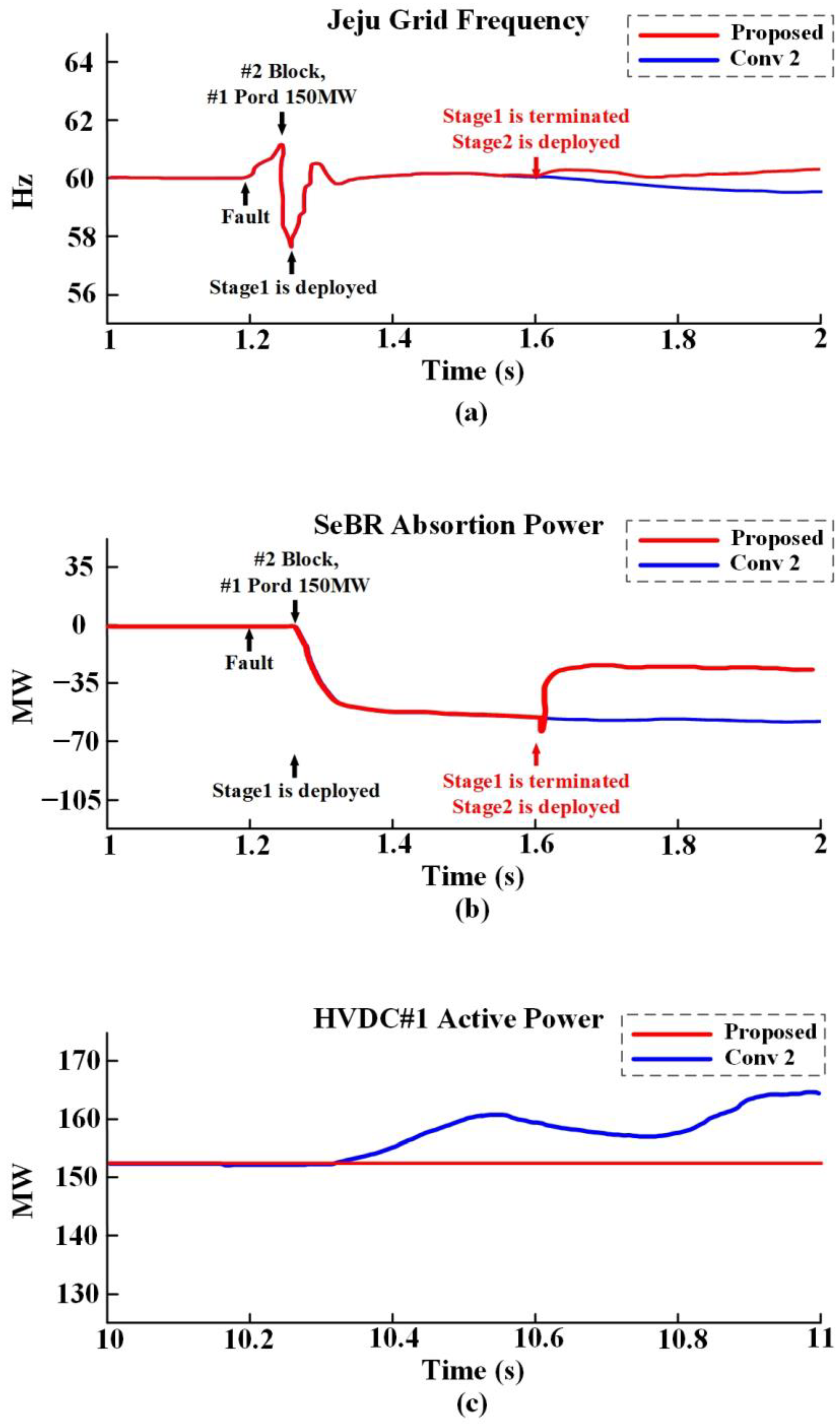
5.4. Verification of Proposed SeBR in the CIGRE HVDC Benchmark Model Environment

In order to verify that the SeBR facility proposed in this paper operates appropriately in various grid environments, we conducted a case study using the CIGRE HVDC benchmark model. Specifically, we modified the CIGRE HVDC benchmark model for the simulation instead of using the Jeju HVDC #2. The parameters of the CIGRE benchmark model are listed in Table 4. Similar to the case studies using the Jeju HVDC systems, we compared three cases: (1) the proposed method with the proposed SeBR, (2) the conventional 2 method with a conventional SeBR (Conv 2), and (3) the conventional 1 method without the SeBR (Conv 1).
Figure 9a shows the voltage of the HVDC #1, and (b) it shows the power output. In Figure 9a, a fault occurs at 1.2 s, and all cases apply the blocking stage to the faulted HVDC #2 at 1.25 s. Simultaneously, the command value (Pord) of the HVDC #1 was changed to 150 MW. At 1.25 s, Stage 1 of the SeBR was deployed for both the proposed method and conventional method.
Observing both (a) and (b) of Figure 9, it can be seen that the conventional 1 method fails to recover control after the fault due to the control interference from the HVDC #2. In contrast, the proposed method and conventional 2 method successfully recover control, as shown by the normal operation of the voltage and power output of the HVDC #1 after Stage 1 is deployed in both Figure 9a,b. Subsequently, the proposed method recovers further to 0.99 p.u. after 8.35 s (top right part in Figure 9a), ensuring the stable operation of the HVDC #1; the conventional 2 method exhibits a voltage of 0.936 p.u. at the same time.
Figure 10 illustrates the effectiveness of the proposed SeBR as suggested in this paper when using the CIGRE benchmark model. Figure 10a displays the frequency of the Jeju grid, while Figure 10b shows the power absorbed by the SeBR when it is deployed. Figure 10c depicts the power output of the HVDC #1 after the continued deployment of the SeBR beyond 10 s.
In Figure 10a, the proposed method demonstrates frequency recovery by terminating Stage 1 at 1.6 s and deploying Stage 2. However, in the conventional method, only Stage 1 is continuously deployed without the additional deployment of Stage 2, resulting in a continuous decrease in frequency. Additionally, observing Figure 10b, it can be seen that the conventional method consumes a large amount of power continuously after Stage 1 is deployed at 1.25 s. In contrast, in the proposed method, Stage 1 is terminated, and Stage 2 is deployed at 1.6 s, leading to a reduction in power consumed by the SeBR to less than half. Due to these results, the frequency in the conventional method continues to decrease, causing instability in the control of the HVDC #1 after 10 s, as shown in Figure 10c.
The additional case studies demonstrated that even with the CIGRE benchmark model, and we observed similar issues as in the Jeju grid, the proposed SeBR could effectively resolve these issues.

6. Conclusions

In this study, we propose a two-stage SeBR designed to maintain the stable operation of the Jeju HVDC #1 when a three-phase ground fault occurs between the converter station and transformer of the Jeju HVDC #2 in the multi-infeed HVDC network in Jeju Island. In contrast to conventional SeBRs that comprise only resistors, the proposed SeBR incorporates an inductor component in Stage 2, which is activated by frequency detection. This enables the long-term deployment of the SeBR even when the faulted Jeju HVDC #2 applies a blocking stage, thereby continuously impacting the control of the Jeju HVDC #1. Additionally, a detailed model of Korea’s Jeju Island grid was developed to validate the system under actual power network conditions. The simulation results verified the effectiveness of the proposed SeBR, indicating its superior performance over other methods. The proposed SeBR can effectively restore the inverter-side voltage and ensure stable control of the Jeju HVDC #1 by detecting frequency changes and deploying Stage 2, thereby maintaining stable operation. Moreover, the methodology for selecting the parameters of the proposed SeBR, as well as the analyses of its effectiveness and operation strategies considering single-phase faults, are required for future work.

Author Contributions

S.L. conceived and designed the experiments; S.L. and D.K. wrote the paper; J.H. performed data analysis and critically revised the manuscript for important intellectual content. All authors have read and agreed to the published version of the manuscript.

Funding

This research received no external funding.

Data Availability Statement

Data are contained within the article.

Acknowledgments

This study was supported by the Seoul National University of Science and Technology and by the Korea Institute of Energy Technology Evaluation and Planning (KETEP) and the Ministry of Trade, Industry and Energy (MOTIE) of the Republic of Korea (No. RS-2023-00266248).

Conflicts of Interest

The authors declare no conflict of interest.

References

  1. International Energy Agency (IEA). Renewables 2023; IEA: Paris, France, 2023; pp. 1–248. [Google Scholar]
  2. Xiaoyu, Z.; Chao, L.; Zhibing, W. Analysis and control on Sub-synchronous oscillation (SSO) of HVDC transmission for large-scale permanent magnet synchronous generators (PMSG)-based wind farm integration. J. Eng. 2019, 2019, 2440–2444. [Google Scholar] [CrossRef]
  3. Rudan, V.; Saad, H.; Yates, D.; Ahmedi, A.; Oluic, M.; Wijesinghe, S. On control interaction studies of HVDC-connected OWFs—Carbon trust OWA project. Electr. Power Syst. Res. 2023, 220, 109328. [Google Scholar] [CrossRef]
  4. Tavakoli, S.D.; Prieto-Araujo, E.; Gomis-Bellmunt, O. AC Fault Ride through in MMC-Based HVDC Systems. IEEE Trans. Power Deliv. 2022, 37, 2775–2786. [Google Scholar] [CrossRef]
  5. Wu, X.; Cao, B.; Shi, H.; Shi, P.; Wang, Y.; Liao, J.; Li, Y.; Zeng, W. Overvoltage Suppression Strategy of LCC-HVDC Delivery System Based on Hydropower Phase Control Participation. Electronics 2024, 13, 1223. [Google Scholar] [CrossRef]
  6. Sun, P.; Wickramasinghe, H.R.; Khalid, M.; Konstantinou, G. AC/DC fault handling and expanded DC power flow expression in hybrid multi-converter DC grids. Int. J. Electr. Power Energy Syst. 2022, 141, 107989. [Google Scholar] [CrossRef]
  7. Jiang, S.; Xin, Y.; Li, G.; Wang, L. A Novel DC Fault Ride-Through Method for Wind Farms Connected to the Grid through Bipolar MMC-HVDC Transmission. IEEE Trans. Power Deliv. 2020, 35, 2937–2950. [Google Scholar] [CrossRef]
  8. Zhou, H.; Yao, W.; Zhou, M.; Ai, X.; Wen, J.; Cheng, S. Active Energy Control for Enhancing AC Fault Ride-Through Capability of MMC-HVDC Connected with Offshore Wind Farms. IEEE Trans. Power Syst. 2023, 38, 2705–2718. [Google Scholar] [CrossRef]
  9. Zhou, H.; Yao, W.; Sun, K.; Ai, X.; Wen, J.; Cheng, S. Dynamic Reactive Current Optimization Based Onshore AC Fault Ride-through Strategy for MMC-HVDC Integrated Offshore Wind Farms. IEEE Trans. Sustain. Energy 2024, 15, 735–746. [Google Scholar] [CrossRef]
  10. Gao, G.; Wu, H.; Blaabjerg, F.; Wang, X. Fault current control of MMC in HVDC-connected offshore wind farm: A coordinated perspective with current differential protection. Int. J. Electr. Power Energy Syst. 2023, 148, 108952. [Google Scholar] [CrossRef]
  11. Salehi, F.; Golshani, A.; Matsuo, I.B.M.; Dehghanian, P. On Mitigation of Sub-Synchronous Control Interactions in Hybrid Generation Resources. IEEE Trans. Ind. Inform. 2021, 18, 4372–4382. [Google Scholar] [CrossRef]
  12. Gu, M.; Huang, L.; Lv, M.; Bian, R.; Li, G.; Ma, Z.; Hong, C.; Jiang, W.; Qi, X. Adaptive Robust Control Method of Battery Storage Systems for Power Oscillation Suppression of MMC-HVDC Offshore Wind Farms. In Proceedings of the 2023 13th International Conference on Power and Energy Systems (ICPES), Chengdu, China, 8–10 December 2023; pp. 307–312. [Google Scholar]
  13. Luo, C.; Guo, Q.; Hu, Y.; Li, S.; Zhu, Y.; Guo, H. Analysis and Countermeasures of Harmonic Instability in a Practical HVDC System with Fixed Series Compensation and STATCOM. IEEE Trans. Ind. Appl. 2023, 59, 2509–2518. [Google Scholar] [CrossRef]
  14. Li, G.; Chen, Y.; Luo, A.; Liu, X. Wideband Harmonic Voltage Feedforward Control Strategy of STATCOM for Mitigating Subsynchronous Resonance in Wind Farm Connected to Weak Grid and LCC HVDC. IEEE J. Emerg. Sel. Top. Power Electron. 2021, 9, 4546–4557. [Google Scholar] [CrossRef]
  15. Kim, K.; Kim, B.; Kim, I. A Study on the Global HVDC Trends and the Current Status of HVDC in Korea. Trans. Korean Inst. Electr. Eng. 2023, 72, 321–329. [Google Scholar] [CrossRef]
  16. Park, K.H.; Baek, S.T.; Chung, Y.H.; Jang, G.S. The Development of the ±80kV 60MW HVDC System in Korea. J. Electr. Eng. Technol. 2017, 12, 594–600. [Google Scholar] [CrossRef]
  17. Kim, C.K.; Jang, G.; Jeong-Boo, K.; Shim, U.B. Transient performance of Cheju-Haenam HVDC system. In Proceedings of the 2001 Power Engineering Society Summer Meeting, Vancouver, BC, Canada, 15–19 July 2001; pp. 343–348. [Google Scholar]
  18. Kunder, K. Power System Stability and Control, 1st ed.; McGraw-Hill: New York, NY, USA, 1971; pp. 528–533. [Google Scholar]
  19. Kim, C.K.; Kwon, Y.H.; Jang, G. New HVDC Interaction between AC network and HVDC Shunt Reactor on Jeju Converter Station. In Proceedings of the 2007 IEEE Power Engineering Society General Meeting, Tampa, FL, USA, 24–28 June 2007; pp. 1–4. [Google Scholar]
  20. Rahimi, E.; Gole, A.; Davies, B.; Fernando, I.; Kent, K. Commutation failure analysis in multi-infeed HVDC systems. In Proceedings of the 2011 IEEE Power and Energy Society General Meeting, Detroit, MI, USA, 24–29 July 2011; pp. 378–384. [Google Scholar]
  21. Gururajapathy, S.S.; Mokhlis, H.; Illias, H.A. Fault Location and Detection Techniques in Power Distribution Systems with Distributed Generation: A Review. Renew. Sustain. Energy Rev. 2017, 74, 949–958. [Google Scholar] [CrossRef]
  22. Australian Energy Market Operator (AEMO). Black System South Australia: Final Report; AEMO: Melbourne, Australia, 2017. [Google Scholar]
  23. Mukhopadhyay, P.; Anumasula, R.; Gartia, A.; Kumar, C.; Seshadri, P.; Patil, S. Case Study on Fault Analysis Using PMU. In Proceedings of the 2014 National Power Systems Conference (NPSC), Guwahati, India, 18–20 December 2014; pp. 1–8. [Google Scholar]
  24. Lee, Y.; Hur, J. Practical Generation Resource Planning Based on Screening Curve Method Considering Must-Run Constraints: The Case of Jeju Island’s Power Grids. IEEE Access 2023, 11, 139260–139271. [Google Scholar] [CrossRef]
  25. Dai, R.; Hwang, M.D.; Qiu, W.; Wang, W.; Liu, X.; Xia, Y. EMS experience of reactive power control for LCC based HVDC system. In Proceedings of the 2015 IEEE Power & Energy Society General Meeting, Denver, CO, USA, 26–30 July 2015; pp. 1–5. [Google Scholar]
  26. Chae, S.H.; Kang, M.H.; Song, S.-H.; Kim, E.-H. Analysis of the Jeju Island Power System with an Offshore Wind Farm Applied to a Diode Rectifier HVDC. Energies 2019, 12, 4515. [Google Scholar] [CrossRef]
  27. Marken, P.E.; Skliutas, J.P.; Sung, P.Y.; Kim, K.S. New synchronous condensers for Jeju Island. In Proceedings of the 2012 IEEE Power and Energy Society General Meeting, San Diego, CA, USA, 22–26 July 2012; pp. 1–6. [Google Scholar]
  28. Liu, W.; Li, G.; Liang, J.; Ugalde-Loo, C.E.; Li, C.; Guillaud, X. Protection of Single-Phase Fault at the Transformer Valve Side of FB-MMC-Based Bipolar HVdc Systems. IEEE Trans. Ind. Electron. 2020, 67, 8416–8427. [Google Scholar] [CrossRef]
  29. Li, Y.; Wang, X.; Guo, J.; Wu, H.; Zhao, B.; Wang, S.; Wu, G.; Wang, T. PLL Synchronization Stability Analysis of MMC-Connected Wind Farms Under High-Impedance AC Faults. IEEE Trans. Power Syst. 2021, 36, 2251–2261. [Google Scholar] [CrossRef]
  30. Zhang, Q.; Mao, M.; Ke, G.; Zhou, L.; Xie, B. Stability problems of PV inverter in weak grid: A review. IET Power Electron. 2020, 13, 2165–2174. [Google Scholar] [CrossRef]
  31. Musengimana, A.; Li, H.; Zheng, X.; Yu, Y. Small-Signal Model and Stability Control for Grid-Connected PV Inverter to a Weak Grid. Energies 2021, 14, 3907. [Google Scholar] [CrossRef]
  32. Hamood, M.A.; Marjanovic, O.; Carrasco, J. Adaptive Impedance-Conditioned Phase-Locked Loop for the VSC Converter Connected to Weak Grid. Energies 2021, 14, 6040. [Google Scholar] [CrossRef]
  33. Li, T.; Li, Y.; Zhu, Y. Research on the Voltage Supporting Capability of Multi-VSC-HVDC Subsystems Operation Strategy to Receiving-end LCC-HVDC Network in Weak AC Grid. CES Trans. Electr. Mach. Syst. 2023, 7, 11–20. [Google Scholar] [CrossRef]
  34. Li, Z.; Xu, H.; Wang, Z.; Yan, Q. Stability Assessment and Enhanced Control of DFIG-Based WTs during Weak AC Grid. IEEE Access 2022, 10, 41371–41380. [Google Scholar] [CrossRef]
  35. Morris, J.F.; Ahmed, K.H.; Egea-Àlvarez, A. Standardized Assessment Framework for Design and Operation of Weak AC Grid-Connected VSC Controllers. IEEE Access 2021, 9, 95282–95293. [Google Scholar] [CrossRef]
  36. Ramadhan, U.F.; Suh, J.; Hwang, S.; Lee, J.; Yoon, M. A Comprehensive Study of HVDC Link with Reserve Operation Control in a Multi-Infeed Direct Current Power System. Sustainability 2022, 14, 6091. [Google Scholar] [CrossRef]
  37. Jung, A.; Park, J.; Lee, H.; Lee, B. Evaluation of inertia resource for securing nadir frequency in HVDC interconnected system with high penetration of RES. Energy Rep. 2023, 9, 1374–1383. [Google Scholar] [CrossRef]
  38. Kim, C.K.; Jang, G. Development of Jeju–Haenam HVDC system model for dynamic performance study. Int. J. Electr. Power Energy Syst. 2006, 28, 570–580. [Google Scholar] [CrossRef]
  39. Kwon, D.; Kim, Y.; Moon, S.; Kim, C. Modeling of HVDC System to Improve Estimation of Transient DC Current and Voltages for AC Line-to-Ground Fault—An Actual Case Study in Korea. Energies 2017, 10, 1543. [Google Scholar] [CrossRef]
  40. Kwon, D.; Kim, Y. Analyses and Comparisons of Generic and User Writing Models of HVDC System Considering Transient DC Current and Voltages. Energies 2021, 14, 7897. [Google Scholar] [CrossRef]
  41. Yan, S.; He, Z.; Yang, J.; Kong, M.; Hu, M. Optimized Protection Strategies for HVDC Grid with Fault-blocking Modular Multilevel Converters for Overhead Line Applications. J. Mod. Power Syst. Clean Energy 2020, 8, 1168–1177. [Google Scholar] [CrossRef]
  42. Liu, Y.; Zhu, X.; Deng, J.B.; Guo, J. Research on protection block strategy of grounding faults in HVDC converter station. J. Eng. 2019, 2019, 1016–1019. [Google Scholar] [CrossRef]
  43. Wang, P.; Zhang, X.P.; Coventry, P.F.; Li, Z. Control and protection strategy for MMC MTDC system under converter-side AC fault during converter blocking failure. J. Mod. Power Syst. Clean Energy 2014, 2, 272–281. [Google Scholar] [CrossRef]
  44. Robak, S.; Gryszpanowicz, K. Comprehensive dimensioning of series braking resistor for transient stability improvement. Electr. Power Syst. Res. 2018, 154, 59–66. [Google Scholar] [CrossRef]
  45. Ministry of Trade, Industry and Energy (MOTIE). Standards for Maintaining Power System Reliability and Power Quality; MOTIE Notice No. 2023-65; Ministry of Trade, Industry and Energy (MOTIE): Sejong, Republic of Korea, 25 April 2023.
Figure 1. Simplified schematic of the test system including the Jeju high-voltage direct current (HVDC) #1 and #2 systems.
Energies 17 04112 g001
Figure 2. Control mode selection of the Jeju HVDC systems: (a) rectifier; (b) inverter.
Energies 17 04112 g002
Figure 3. Diagram of the converter blocking status of the Jeju HVDC systems: (a) rectifier; (b) inverter.
Energies 17 04112 g003
Figure 4. Operational schematic of the proposed series braking resistor (SeBR): (a) normal operation; (b) proposed SeBR operation: Stage 1; (c) proposed SeBR operation: Stage 2.
Energies 17 04112 g004
Figure 5. Operational workflow of the SeBR.
Energies 17 04112 g005
Figure 6. Comparison of reactive power and voltage of PCC obtained from the proposed, conventional 1 (Conv 1), and conventional 2 (Conv 2) methods: (a) reactive power flow of PCC in all cases; (b) voltage of PCC in all cases.
Energies 17 04112 g006
Figure 7. Comparison of the results obtained from the proposed, conventional 1 (Conv 1), and conventional 2 (Conv 2) methods: (a) voltage of the Jeju HVDC #1 in all cases; (b) power output of the Jeju HVDC #1 in all cases.
Energies 17 04112 g007
Figure 8. Comparison between the proposed method and conventional 2 (Conv 2) methods: (a) Jeju grid frequency; (b) active power absorbed by the SeBR; (c) power output of the Jeju HVDC #1 after 10 s.
Energies 17 04112 g008
Figure 9. Comparison of CIGRE benchmark model results obtained from the proposed, conventional 1 (Conv 1), and conventional 2 (Conv 2) methods: (a) voltage of HVDC #1 in all cases; (b) power output of HVDC #1 in all cases.
Energies 17 04112 g009
Figure 10. Comparison between the proposed method and conventional 2 (Conv 2) methods on CIGRE benchmark model: (a) Jeju grid frequency; (b) active power absorbed by the SeBR; (c) power output of HVDC #1 after 10 s.
Energies 17 04112 g010
Table 1. Detailed parameters of the converter blocking status of Jeju high-voltage direct current (HVDC) systems.
ParametersDescriptions and Sample Values
Vrec_acRectifier side AC bus voltage
Vinv_acInverter side AC bus voltage
VBLOCKRectifier AC blocking voltage
VINBLKInverter AC voltage that causes the block after communication delay TCOMB
TBLOCKMinimum blocking time
TCOMBCommunication delay in signaling the rectifier to block because of low inverter voltage
Table 2. Detailed parameters of the test system.
DevicesDescriptionParametersValue
Jeju HVDC #1Nominal DC voltage [kV]Vdcr1, Vdci1183.9, 182.7
Nominal DC [A]Idcr1, Idci1282
HVDC DC link length [km]-101
HVDC parameter of inductor [mH]LTR1, Lline1
Lrec1, Linv1
22.5, 9.6,
60, 60
DC line capacitor [μF]Cline127.7
DC line resistor [Ω]Rline12.5
Jeju HVDC #2Nominal DC voltage [kV]Vdcr2, Vdci2254.4, 252.7
Nominal DC [A]Idcr2, Idci2312.4
HVDC DC link length [km]-113
HVDC parameter of inductor [mH]LTR2, Lline2
Lrec2, Linv2
22.5, 16.18,
60, 60
DC line capacitor [μF]Cline265.3
DC line resistor [Ω]Rline22.44
SeBRRated voltage [kV]-154
Rated MVA [MVA]-100
Stage 1 [p.u.]R11
Stage 2 [p.u.]R2, L10.3, 0.7
Jeju HVDC Systems’ Control Mode SelectionDC voltage [p.u.]Vdcr_max, Vdci_max1.0, 1.2
DC current [p.u.]Idcr_max, Idcr_min, Idci_max1.3, 1.2, 1.2
Alpha and Gamma [°]αmax, αmin, γmax165°, 5°, 18°
PI gainsKp1, Kp2, Kp3,
Kp4, Kp5
0.01, 1.3, 1.42
0.01, 0.1
PI gainsKi1, Ki2, Ki3,
Ki4, Ki5
0.01, 2.5, 5.5
0.01, 0.01
Jeju HVDC Systems’ Converter Blocking StatusAC bus voltage [p.u.]Vrec_ac, Vinv_acMeasurement value
AC blocking voltage [p.u.]VBLOCK0.6
AC blocking voltage [p.u.]VINBLK0.65
Minimum blocking time [p.u.]TBLOCK0.1
Communication delay [s]TCOMB0.05
Table 3. Comparison of the proposed method with other methods.
CaseSeBRJeju HVDC #2 BlockJeju HVDC #1 Pord 150 MW
PropStage 1, Stage 2OO
Conv 1XOO
Conv 2Stage 1OO
Table 4. Detailed parameters of the CIGRE HVDC benchmark model.
DevicesDescriptionParameters
CIGRE HVDCAC base voltageRectifier: 345 [kV]
Inverter: 230 kV
Nominal DC voltage500 [kV]
Nominal DC current2 [kA]
DC line impedance (Rec side)R = 2.5 [Ω]
L = 0.5968 [H]
DC line impedance (Inv side)R = 2.5 [Ω]
L = 0.5968 [H]
System frequency60 [Hz]
Converter controlRectifier: current
Inverter: voltage
Disclaimer/Publisher’s Note: The statements, opinions and data contained in all publications are solely those of the individual author(s) and contributor(s) and not of MDPI and/or the editor(s). MDPI and/or the editor(s) disclaim responsibility for any injury to people or property resulting from any ideas, methods, instructions or products referred to in the content.

