Article

Experimental Investigation of R404A Indirect Refrigeration System Applied Internal Heat Exchanger: Part 1—Coefficient of Performance Characteristics

by
Min-Ju Jeon
and
Joon-Hyuk Lee
*
Department of Refrigeration and Air-Conditioning Engineering, College of Engineering, Pukyong National University, 45, Yongso-ro, Nam-Gu, Busan 48513, Republic of Korea
*
Author to whom correspondence should be addressed.
Energies 2024, 17(16), 4127; https://doi.org/10.3390/en17164127
Submission received: 15 July 2024 / Revised: 7 August 2024 / Accepted: 13 August 2024 / Published: 19 August 2024
(This article belongs to the Section J: Thermal Management)

Abstract

:
In this study, the performance characteristics of an R404A indirect refrigeration system (IRS) applied to an internal heat exchanger (IHX) is evaluated for supermarkets and hypermarkets. In a direct expansion system, R404A is the primary refrigerant and R744, a brine, is the secondary fluid. While there are abundant studies analyzing the theoretical performance of IRS, experimental research on IRS is lacking, and there are no papers that address the results of changes in the IHX in detail. In this study, the results achieved by modifying various parameters are experimentally evaluated to provide fundamental data for designing the optimal IRS. In the main results, looking at the trend of the increase in IHX efficiency, the change is very minimal when the efficiency is above 50%, so it is ideal to apply an IHX efficiency of about 50% considering economics and COP, etc. Applying the results in this study enables the operation and maintenance of IRSs as an eco-friendly system by achieving energy efficiency through optimizing the system coefficient of performance and securing economic feasibility by minimizing the R404A charging amount of the refrigeration cycle. To serve supermarkets and hypermarkets, R744 as a secondary fluid may help to realize an ecologically friendly, compact IRS system with a high heat transfer coefficient that can operate at low temperatures (−35 to 5 °C).

1. Introduction

Refrigeration technology has been widely utilized in various fields to accommodate continuous societal development [1,2,3]. The establishment of the Montreal Protocol in 1987, the Refrigerant Declaration of the Swedish Environmental Protection Agency in 1989, and the Kyoto Protocol in 1997, however, has raised interest in the ozone depletion potential (ODP) and global warming potential (GWP). Moreover, mixed refrigerants used in refrigeration systems other than natural refrigerants have been recognized as significant contributors to ozone depletion and global warming. The use of chlorofluorocarbons, hydrochlorofluorocarbons, and hydrofluorocarbons has been gradually reduced internationally owing to their high ODP and GWP [4,5]. In the case of refrigeration systems installed in supermarkets and hypermarkets as Table 1 [6], refrigerants that do not pose risks of explosion, toxicity, and flammability must be used to avoid harm to people. As R404A is classified as group A1 according to the ASHRAE 34 standard [7], it is a safe refrigerant for supermarkets and hypermarkets [8]. Additionally, R404A can be used in developing countries despite its high GWP. Measures to reduce the risk of refrigerant leakage must be devised to prevent severe accidents [9]. An excellent option is to use indirect refrigeration systems (IRSs) [10,11]. This is because IRSs can minimize the refrigerant charge and reduce the risk of primary refrigerant leakage by replacing the primary refrigerant with the secondary fluid.
Supermarkets and hypermarkets use centralized commercial refrigeration systems with multiplexed direct expansion systems (MDXS), which contribute the most to global warming owing to their high refrigerant charge (300 to 3000 kg [12]) and annual leakage rate (15% to 25% [13]). According to Wang [10], Palm [14], and Melinder [15], using an IRS instead of a direct expansion system (DXS) can reduce the refrigerant charge by up to 90%. An IRS prevents refrigerant leakage through distribution lines and services; furthermore, it reduces the overall annual leakage rate because the refrigerant is contained in the machine room.
Single-phase brine has been used as the secondary fluid in IRSs; however, it consumes a significant amount of power for the pump, and its sensible heat exchange is lower than the latent heat exchange of the refrigerant [16,17]. Hence, R404A has been commonly used as the primary refrigerant for IRSs installed in supermarkets and hypermarkets. In addition, R744 (CO2) has been applied as a secondary fluid [18,19,20,21].
The performance of IRSs for MDXSs has been investigated via simulation. Clodic et al. [22] simulated a French supermarket with a sales area of 10,000 m2 using propylene-glycol/water for the medium-temperature level (MT) and Tyfoxit for the low-temperature level (LT), as well as the R404A basic system for a parallel R404A MDXS. Because the introduction of the second loop diminished the evaporation temperature by 6K for the MT and 7K for the LT, the refrigerant charge reduction rate of the system with respect to the DXS was 56%. Horton [23] compared an R22 MDXS with an ammonia-HFE7100 IRS and discovered that the former consumed less energy by 15%. By performing a simulation using field data, Arias [24] compared an R404A MDXS used in a 2700 m2 supermarket with a similar system that used indirect loops with 35% vol. propylene-glycol/water for the MT and R744 for the LT. Based on estimation, switching to the indirect solution can reduce the refrigerant charge by 90%. Additionally, the total emission from the system to the atmosphere was estimated. For Sweden, the emissions diminished by 74.0% for a case with an indirect emission coefficient of 0.04 kg·CO2·kWh−1. Considering the average indirect emission coefficient of Europe (0.51 kg·CO2·kWh−1), however, the reduction was only 20.7% owing to the raised energy consumption of the indirect solution.
Meanwhile, Beshr et al. [25] simulated an R404A MDXS for the MT and LT; in particular, a system using N40A as the main refrigerant and a split system using directly expanding N40 and L40 with a propylene-glycol/water mixture loop for the LT were simulated. They discovered that direct emissions were reduced by 89% and 65%, respectively, when indirect solution and N40 were used at an annual leakage rate of 10%. They reported that the indirect solution will provide a good balance between indirect emissions and energy consumption if the average annual leakage rate is 10% in cold climates and less than 2% for all climates [22].
You [26] experimentally investigated an R404A DXS equipped with a supercooler indirect system that used Temper 40® as a secondary fluid. Faramarzi and Walker [27] presented the performance results of a 3900 m2 hypermarket that used an R507A MDXS and secondary fluid loops for the MT and LT in the same primary plant. In a corresponding factory that performed heat removal using an evaporative condenser, the energy consumption was reduced by 4.9% under only a 10% refrigerant charge.
Other experimental studies pertaining to commercial IRSs focused only on system performance, whereas the energy effects of multiplexed solutions were not considered [28,29,30,31,32].
Among various refrigeration systems, IRSs using the R404A refrigerant are often installed and applied in large marts and supermarkets. And despite increasing studies regarding IRSs, only a few have experimentally investigated the effects of the primary refrigerant and secondary fluid on the overall system performance under various operating conditions. Few experimental studies of R404A IRSs have been conducted, and in the few cases where an internal heat exchanger (IHX) has been applied, simple comparisons have been made between systems with and without an IHX, and no extensive studies have been conducted for different efficiencies of the internal heat exchanger. Therefore, in this study, the coefficient of performance (COP) and mass flow rate (MFR) of an R404A IRS with an IHX, which improves the performance of refrigeration systems operating at low temperatures (−35 to 5 °C) and uses R744 as a secondary fluid, was analyzed under the same experimental conditions based on the degree of subcooling (DSC) and superheating at the R404A cycle, the degree of superheating (DSH) at the R744 cycle, the condensation temperature, the evaporation temperature of a cascade heat exchanger (CHX), and the IHX efficiency. The experiments and analysis were conducted to offer fundamental data for designing the optimal R404A IRSs with IHXs operating at low temperatures using R744 as a secondary fluid.

2. Test Device and Data Analysis
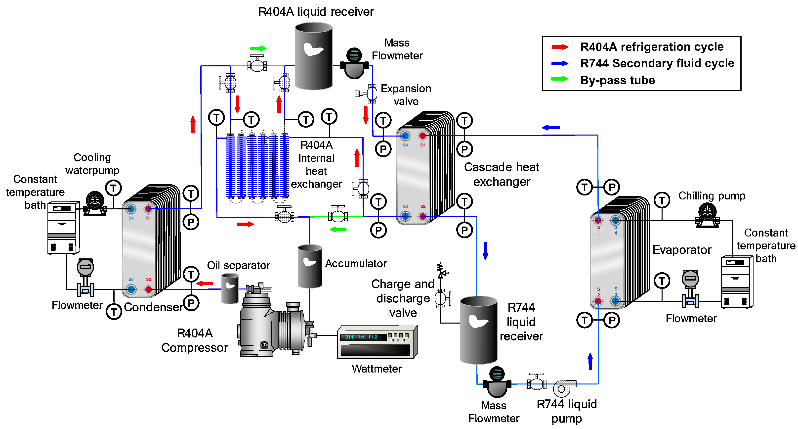
To achieve a low temperature range of −35 to 5 °C, an experiment was performed by constructing an R404A IRS (Custom-developed, Busan, Republic of Korea) that combined an R404A DXS and a refrigerant circulation loop operated via an R744 liquid pump (Micropump, WA, USA). Herein, factors affecting an IHX-equipped R404A IRS using R744 as a secondary fluid were theoretically identified and analyzed. Subsequently, the COP of the IRS was analyzed.

2.1. Test Device

A schematic of the test device (Figure 1) was constructed to characterize an IRS that used R744 as a secondary fluid. To obtain the data required for the evaluation and calculation of the power consumption of the compressor (PCC) (Bock, Frickenhausen, Germany), the power consumption of the pump, the refrigeration capacity, and the COP, the refrigerant pressure, temperature, and MFR, as well as the power consumptions of the refrigerant pump and compressor, were measured at each position inside the IRS. The measurement positions are also shown in Figure 1. As shown in Figure 1, the test device primarily comprised R404A and R744 refrigerant circulation loops and heat-source water circulation loops. These loops were forced circulation loops circulated by the heat-source water pump and each refrigerant compressor. The R404A refrigerant circulation loop (R404A refrigeration cycle; R404A RC) was composed of a semi-closed compressor (reciprocating), a condenser (Alfa Laval, Lund, Sweden), an oil separator, an IHX (double-tube type), a receiver, a mass flowmeter (OVAL, Tokyo, Japan), an expansion valve (EV), a CHX (Alfa Laval, Lund, Sweden), and an accumulator. The R744 refrigerant circulation loop (R744 secondary fluid cycle; R744 SFC) comprised a refrigerant pump, an evaporator (Custom-developed, Busan, Republic of Korea), a CHX, a receiver, and a mass flowmeter. Each heat-source water loop was composed of a water flowmeter (Corea Flow, Siheung, Republic of Korea), a constant-temperature bath, and a water pump.
As you can see in Figure 1, R404A refrigerant steam of the high-pressure and high-temperature from the compressor goes into the condenser to exchange heat with the heat-source water, and the liquid refrigerant enters into the receiver. The mass flowmeter feeds receiver liquid refrigerant into the EV. At this instant, the refrigerant flow rate and density are measured using the mass flowmeter to identify the condition of R404A. The liquid refrigerant that passed through the EV enters the CHX (which serves as an evaporator) to exchange heat with the R744 refrigerant and then enters the compressor for recirculation. After exchanging heat with R404A, R744 is cooled and enters the receiver in liquid form. The liquid refrigerant from the receiver flows through the mass flowmeter and enters the evaporator through the R744 refrigerant pump. It exchanges heat with the heat-source water, thus transforming it into steam, and then enters the CHX (which serves as a condenser) for recirculation. The temperature of the heat-source water that enters the condenser and evaporator through the flowmeter remains constant in the constant-temperature bath. In addition, Table 2 and Table 3 provide information on the main components and measuring equipment used in this study [33].

2.2. Test Methodoloy

The airtightness of the test device was tested by injecting nitrogen until the compressor pressure limit was attained. A leak test was performed the day following the injection. After the test indicated no issues, nitrogen was released, and a vacuum pump vacuumed the system. Subsequently, purging was conducted three times by injecting trace amounts of the refrigerant and using a vacuum pump to create a vacuum to remove internal impurities. Before putting the IRS into operation, the inlet temperatures of the evaporator and R404A condenser were adjusted via two constant-temperature baths, and the liquid refrigerants were charged into each system. The experiment was performed in the following sequence:
  • The cooling-water and heat-source water temperatures of the constant-temperature baths were adjusted to the required temperature.
  • The compressor was turned on, and the compressor–inverter frequency and EV were adjusted to establish the MFR and evaporation temperature at the R404A RC.
  • After running the R404A RC, the condition of the liquid refrigerant obtained from the R744 receiver was examined, and then the pump was operated.
  • The subcooling and superheating degrees of the system were set by adjusting the R744 and cooling-water flow rates.
When the IRS reached the pressure, temperature, steady state, and MFR at each measurement position, they were measured using specific measuring equipment, and the data were sent to a computer via GPIB communication. After the system reached the steady state (the system was assumed to be in the steady state if the temperature change was less than 0.5 °C, the pressure change was less than 5 kPa, and the MFR change was less than 0.05 kg/min for 15 min), the pressure, temperature, and MFR of the refrigerant as well as the power consumed by the compressor and pump were measured thrice at 5 min intervals. Table 4 shows the test conditions.

2.3. Data Analysis and Uncertainties

The data presented in Table 4 and the following calculation formulas were used for data analysis to characterize the IRS that used R744.
IRSs feature two COPs: the COP of the R404A RC (COPR404A) and the COP of the IRS (COPSYS). The COP of the R404A RC, which is typically similar to a one-stage compression and expansion refrigeration system, was analyzed by utilizing Equation (1). Lin and Jiang [34] calculated the COP of an IRS using Equation (2). In Equation (2), the R744 evaporation heat capacity (EHC) was used in the numerator because it was the most important and was directly used in an IRS. The power levels consumed by the compressor and pump for R404A and R744, respectively, were used in the denominator because the input work of the entire system included the power consumption by both the pump and the compressor.
C O P R 404 A = Q E , C A S W C O M , R 404 A
C O P S Y S = Q E W C O M , R 404 A + W P U M , R 744
where W C O M , R 404 A and W P U M , R 744 are the power consumption [kW] by the pump and compressor, respectively.
The MFR ratio of the IRS ( m ˙ R A T I O ) was calculated as follows:
m ˙ R A T I O = m ˙ R 404 A m ˙ R 744
The IHX efficiency can be expressed as shown in Equation (4) and Figure 2.
η I H X , R 404 A = ( T 1 T 8 ) ( T 4 T 8 )
The thermal properties of R404A and R744 applied in the R404A IRS were analyzed utilizing REFPROP 8.01. The performance characteristics of R404A IRS were investigated based on the thermal properties of R404A and R744. The calculation formulas utilized to analyze the test data are summarized in Table 5. The COPR404A and COPSYS were calculated using Equations (1)–(3) [35].
The test results used for design and engineering interpretation are generally inaccurate. Thus, the uncertainties of the test results were expected in this study, as shown in Table 6, using formulas proposed by Moffat [36] and Kline and McClintock [37].

3. Results

In this section, the characteristics and performance of an IRS applying R744 as a secondary refrigerant are analyzed to provide foundational design data. Specifically, the COP was considered based on the R404A condensation and evaporation temperature, R404A IHX efficiency, R404A DSH and DSC, R744 cooler temperature difference, R744 evaporation temperature, R744 DSH, and R744 MFR.

3.1. Influence on DSH

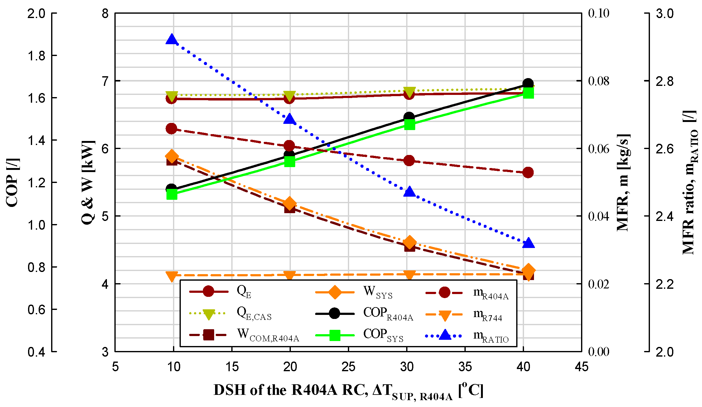
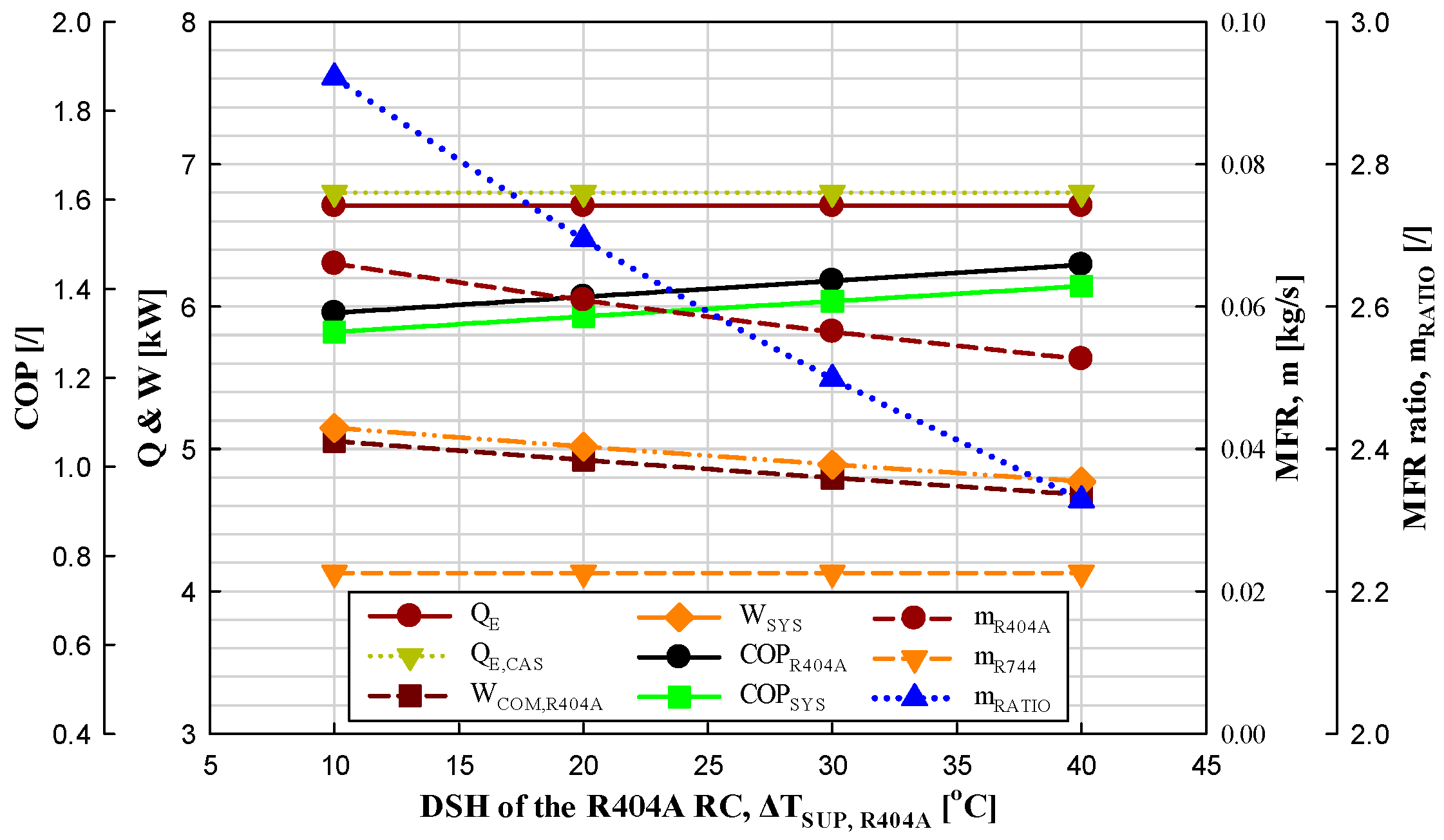
3.1.1. Influence on DSH at the R404A RC

The COPs of the R404A RC and IRS, as well as the MFR ratio, were experimentally investigated as the DSH at the R404A RC rose by approximately 10 °C from 9.9 to 40.5 °C under the following conditions: QE = 6.73–6.82 kW; TE = −21.5–−21.3 °C; TE,CAS = −25.4–−24.9 °C; TC = 39.8–40.1 °C; ΔTSUB,R404A = 1.1–1.4 °C; ΔTSUP,R744 = 9.5–10.6 °C; ΔTSUB,R744 = 1.3–1.9 °C; ΔTCAS = 3.5–3.9 °C; and η IHX,R404A = 0.
As shown in Figure 3, as the DSH at the R404A RC rose by 10 °C, the COPs of the R404A RC and IRS rose by 10.6–13.8% and 10.1–13.5%, respectively, based on Equations (1) and (2). This is due to the fact that the evaporation heat capacity (EHC) and cascade EHC rose slightly by 0–0.9% and 0.1–0.8%, respectively, whereas the PCC of the R404A RC was diminished by 9.2–12.1% and the DSH of the R404A RC rose by approximately 10 °C, as shown in Table 5. Based on speculation, the PCC was diminished for the reason that the difference between the inlet enthalpy (IE) and outlet enthalpy (OE) of the compressor (h2-h1) was diminished by 3.1–4.7% despite an increase in the enthalpies of both the inlet and outlet (h1 and h2, see Table 4), as well as because the MFR of the R404A RC was diminished by 6.2–7.7%. These results are attributed to the properties of R404A, and they show the same trend as the papers of Son and Moon [38] and Kumar et al. [39].
In addition, as the DSH of the R404A RC rose, the MFR of the R404A RC was diminished by 6.3–7.7%, whereas that of the R744 SFC was minimally affected (decrease of 0–0.9%). Thus, the MFR ratio in the IRS was diminished by 6.2–8.1% based on Equation (3). Here, the MFR of the R404A RC appeared to have diminished due to the energy equilibrium in the CHX, as the enthalpy at the outlet of the cascade evaporator (CE) (h8) rose, despite no change in the MFR of the R744 SFC or the IE of the CE (h6). This finding shows the same trend as the results of the paper by Kumar et al. [39], who conducted a similar study to this study. Therefore, it was concluded that the COP rises and the MFR ratio is diminished while the DSH of the R404A RC rises.

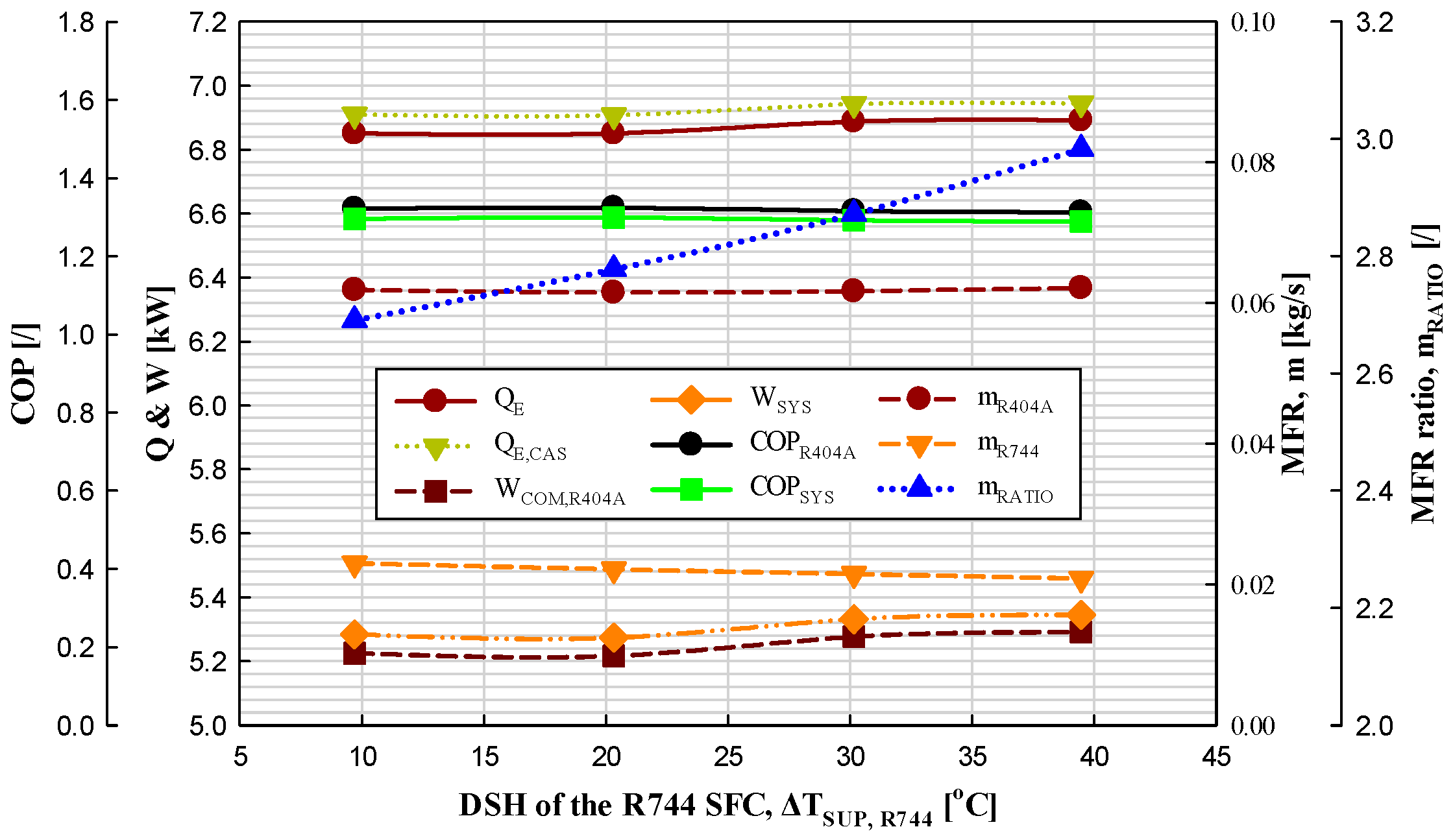
3.1.2. Influence on DSH at the R744 SFC

The COPs of the R404A RC and IRS, as well as the MFR ratio, were experimentally investigated as the DSH of the R744 SFC rose by approximately 10 °C from 9.7 to 39.5 °C under the following conditions: QE = 6.85–6.89 kW; TE = −21.3–−21.0 °C; TE,CAS = −25.4–−24.9 °C; TC = 39.8–40.1 °C; ΔTSUP,R404A = 19.7–20.1 °C; ΔTSUB,R404A = 1.1–1.3 °C; ΔTSUB,R744 = 1.1–1.6 °C; ΔTCAS = 3.4–3.9 °C; and η IHX,R404A = 0.
As shown in Figure 4, as the DSH at the R744 SFC rose by approximately 10 °C, and the COPs of the R404A RC and IRS were diminished by 0.2–0.6% and 0.2–0.5%, respectively. This is because the EHC of the R404A RC and IRS rose by 0.1–0.5% and 0–0.5%, respectively, and the PCC rose by 0.2–1.2%. Although the power consumption of the pump at the R744 SFC was diminished by 3.1–3.6%, the COP was unaffected, as the magnitude was insignificant compared with the PCC. Eventually, the COPs of the R404A RC and IRS were assumed to have diminished slightly for the reason that the increase rate of the PCC was higher than that of EHC. This is the same trend as the research result of Mosaffa et al. [40].
In addition, as the DSH of the R744 SFC rose, the MFR of the R404A RC rose or diminished by 0.3–0.7%, whereas that at the R744 SFC diminished by 3–3.7%. Accordingly, the MFR ratio between R404A and R744 rose by 3.2–3.9%. This is because the MFR at R744 diminished as the DSH rose under the relatively constant EHC at the R744 evaporator due to the energy equilibrium of the CHX. Therefore, it was concluded that the COP decreased and the MFR ratio increased while the DSH of the R744 SFC increased.

3.2. Influence on DSC

Influence on DSC at the R404A RC

The COPs of the R404A RC and IRS as well as the MFR ratio were experimentally investigated as the DSC at the R404A RC rose by approximately 5 °C from 1.4 to 19.5 °C under the following conditions: QE = 6.87–6.95 kW; TE = −21.8–−21.4 °C; TE,CAS = −25.5–−24.7 °C; TC = 39.7–40.3 °C; ΔTSUP,R404A = 19.6–20.4 °C; ΔTSUP,R744 = 9.7–10.2 °C; ΔTSUB,R744 = 1.1–1.5 °C; ΔTCAS = 3.1–3.5 °C; and η IHX,R404A = 0.
As shown in Figure 5, while the DSC at the R404A RC rose by approximately 5 °C, the COP of the R404A RC rose by 4.5–7.1%, and the COP of the IRS rose by 4.4–7%. This is because the IE of the CE (h6) diminished by 2.3–3.3% as the DSC rose, whereas the IE and OE of the compressor at the R404A RC (h1 and h2) and the OE of the CE (h8) remained unchanged. Accordingly, the difference between the IE and OE of the CE (h8-h6) rose by 4.1–6.8%, whereas the MFR diminished. Therefore, whereas changes in the EHC and cascade EHC were insignificant, since they rose or diminished by only 0.3–1.6%, the PCC diminished by 5.5–6.3%, thereby raising the COPs of the R404A RC and IRS. This is the same trend as that found in the papers of Son and Moon [38] and Kumar et al. [39].
Additionally, as the DSC of the R404A RC rose, the MFR ratio diminished because the MFR of the R404A RC diminished while that of the R744 SFC barely changed. The MFR of the R404A RC diminished by 5.5–6% as the DSC of the R404A RC rose by approximately 5 °C from 1.4 to 19.5 °C. This is because the difference between the IE and OE of the CE rose while the change in the cascade EHC was insignificant, i.e., 6.93–7.0 kW. These findings show the same trend as those of Kumar et al. [39].
Therefore, it was concluded that the COPs of the R404A RC and IRS increased and the MFR diminished while the DSC of the R404A RC rose.

3.3. Influence on Condensation Temperature

The COPs of the R404A RC and IRS, as well as the MFR ratio, were experimentally investigated, as the condensation temperature of the IRS rose by approximately 10 °C from 20.1 to 49.7 °C under the following conditions: QE = 6.81–6.88 kW; TE = −21.6–−21.3 °C; TE,CAS = −25.3–−24.3 °C; ΔTSUP,R404A = 19.5–20.5 °C; ΔTSUB,R404A = 1–1.5 °C; ΔTSUP,R744 = 9.8–10.7 °C; ΔTSUB,R744 = 1.2–1.4 °C; ΔTCAS = 2.9–3.5 °C; and η IHX,R404A = 0.
As can be seen in Figure 6, while the condensation temperature rose by approximately 10 °C, the COP of the R404A RC diminished by 24.8–29.5% and the COP of the IRS diminished by 24.4–29.3%. This was because the PCC rose by 32.5–42.2% as the condensation temperature rose, while the cascade EHC changed insignificantly since it rose or diminished by only 0.4–0.7%. The PCC rose because the difference between the IE and OE of the compressor (h2-h1) rose due to an increase in the OE of the compressor (h2), despite no change in the IE of the compressor (h1) and the MFR increasing by 10.8–17.4%. This is the same trend as the research results of Parmar and Kapadia [41], Hendri et al. [42], Messineo and Panno [43], Parekh and Tailor [44], and Kilicarslan and Hosoz [45].
In addition, while the condensation temperature of the R404A RC rose in the IRS, the MFR of the R404A RC rose by 4.9–7.2% while that of the R744 SFC barely changed, since it rose or diminished by only 0.2–0.6%. Thus, the MFR ratio of the IRS rose by 10.8–17.4%. As the condensation temperature rose, the MFR of the R404A RC rose due to the energy equilibrium of the CHX. This is because the IE of the CE (h6) rose despite the relatively constant MFR of the R744 SFC, cascade EHC (QE,CAS), and OE of the CE (h8). Thus, the difference value between the IE and OE of the CE (h8-h6) diminished by 9.8–14.6%. This is the same trend as that found in the papers of Son and Moon [38] and Parekh and Tailor [44].
Therefore, it was concluded that the COPs of the R404A RC and IRS decreased and the MFR ratio increased as the condensation temperature in the IRS increased.

3.4. Influence on Cascade Evaporation Temperature

The COPs of the R404A RC and IRS, as well as the MFR ratio, were experimentally investigated as the cascade evaporation temperature (CET) rose by approximately 10 °C, from −39.2 to 0 °C, under the following conditions: QE = 13.37–13.45 kW; TE = −35.5–3.5 °C; TC = 39.8–40.2 °C; ΔTSUP,R404A = 19.7 –20.4 °C; ΔTSUB,R404A = 1.4–1.6 °C; ΔTSUP,R744 = 19.8–20.3 °C; ΔTSUB,R744 = 1–1.6 °C; ΔTCAS = 3.1–3.5 °C; and η IHX,R404A = 0.
As shown in Figure 7, while the CET in the IRS rose by approximately 10 °C, the COP of the R404A RC and IRS rose by 22.8–24.3% and 21.4–24%, respectively. This is because the PCC diminished by 29.1–34.3%, even though the EHC and cascade EHC barely changed. While the CET rose, the MFR of the R404A RC diminished by 4–6.4% owing to the energy equilibrium of the CE. This was because the OE of the CE (h8) rose despite no change in the cascade EHC (QE,CAS) or IE of the CE (h6); thus, the difference between the IE and OE of the CE (h8-h6) rose by 4.2–5.9%. In addition, the MFR of the R744 SFC rose by 5.1–9.4% owing to the energy equilibrium. This was because the difference between the IE and OE of the cascade condenser (CC) (h12-h14) diminished by 4.7–9.9% as the OE of the CC (h14) further rose, despite an increase in both the IE and OE of the CC (h12 and h14) under a relatively constant cascade condensation heat capacity (QC,CAS).
Here, the MFR ratio diminished by 11.1–14.8%. Additionally, the COPs of the R404A RC and IRS rose, and the MFR ratio diminished as the CET of the IRS rose. This finding is the same trend as that found in the research of Son and Moon [38], Shilliday et al. [46], and Yi et al. [47].

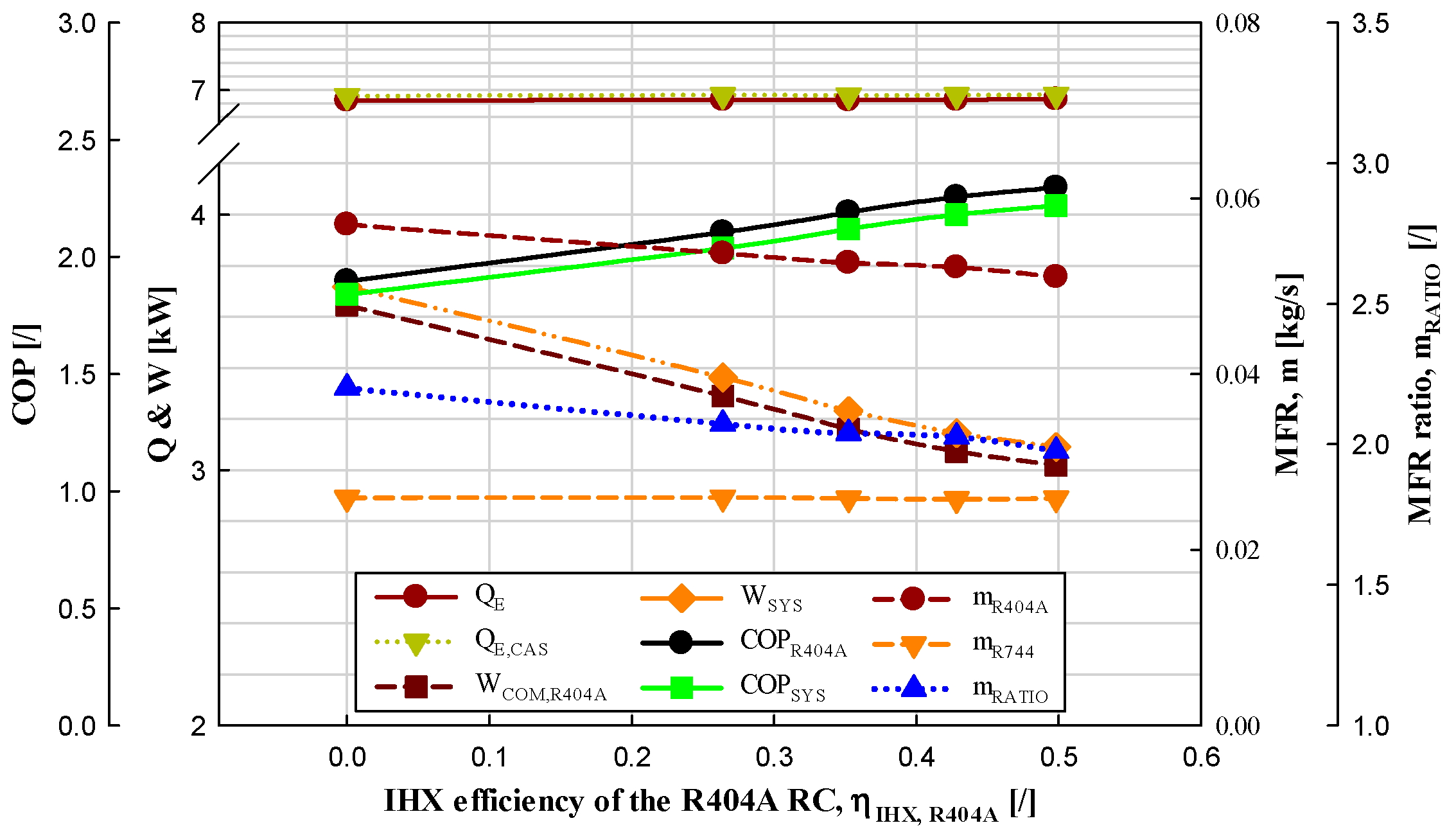
3.5. Influence on IHX Efficiency

The COPs of the R404A RC and IRS, as well as the MFR ratio, were experimentally investigated, while the number of stages of the IHX at the R404A RC raised from zero to four under the following conditions: QE = 6.84–6.86 kW; TE = −6.5–−6.3 °C; TE,CAS = −10.3–−9.6 °C; TC = 39.8–40.3 °C; ΔTSUP,R404A = 19.4–20.3 °C; ΔTSUB,R404A = 1.1–1.5 °C; ΔTSUP,R744 = 9.8–10.5 °C; ΔTSUB,R744 = 1–1.5 °C; ΔTCAS = 3.1–3.6 °C; and η IHX,R404A = 0.
As shown in Figure 8, the IHX efficiencies were 0%, 26.4%, 35.2%, 42.8%, and 49.8%, while the number of stages of the IHX on the R404A side of the IRS rose from zero to four. As the number of stages rose, the COPs of the R404A RC and IRS rose by 1.8–11% and 1.8–10.8%, respectively. The PCC of the R404A RC diminished by 1.8–9.7%, whereas the EHC of the IRS (QE) and the cascade EHC (QE,CAS) remained almost unchanged while the number of stages raised from zero to four. This was because the difference between the IE and OE of the CE (h8-h6) rose by 1.1–6.3% as the IE of the CE (h6) diminished by 0.5–3%, while the OE of the CE (h8) barely changed owing to the efficiency of the IHX. While both the IE and OE of the compressor at the R404A RC (h1 and h2) raised, the increase in the IE (h1) was almost twice as large as the increase in the OE (h2), thereby decreasing the difference between the IE and OE (h2-h1) by 0.4–4.3%. Therefore, the COPs of the R404A RC and IRS rose. This is the same trend as that found in the research papers of Son and Moon [38] and Oruğç and Devecioğlu [48].
In addition, while the number of stages of IHX of the R404A RC rose in IRS, the MFR of the R404A RC diminished by 2.1–5.7% while that of the R744 SFC barely changed. Thus, the MFR ratio at the IRS diminished by 0.6–5.9%. Meanwhile, the MFR of the R404A RC diminished owing to the energy equilibrium of the CE because the difference between the IE and OE of the CE (h8-h6) rose despite a relatively constant cascade EHC. This is the same trend as that found in the research results of Son and Moon [38].
Since the high-efficiency IHX increased the COP at the R404A RC, one can conclude that implementing a highly efficient IHX in the R404A RC would increase the COP and decrease the MFR ratio.

3.6. Comparing Results from Experimental Data and Performance Analysis Data

Figure 3 shows that the COPs of the R404A RC and IRS as well as the MFR ratio were experimentally investigated according to DSH at the R404A RC of IRS, whereas Figure 9 shows the COPs of the R404A RC and IRS as well as the MFR ratio through a performance analysis.
Figure 3 shows the results obtained based on the following conditions: QE = 6.73–6.82 kW; TE = −21.2–−20.9 °C; TE,CAS = −25.4 to −24.9 °C; TC = 39.7–40.2 °C; ΔTSUB,R404A = 1.1–1.5 °C; ΔTSUP,R744 = 9.5–10.6 °C; ΔTSUB,R744 = 1.3–1.9 °C; ΔTCAS = 3.5–3.9 °C; and η IHX,R404A = 0. Meanwhile, the results in Figure 8 were obtained based on the following conditions: QE = 6.71 kW; TE = −21 °C; TE,CAS = −24.9 °C; TC = 40.1 °C; ΔTSUB,R404A = 1.3 °C; ΔTSUP,R744 = 9.9 °C; ΔTSUB,R744 = 1.6 °C; ΔTCAS = 3.7 °C; η IHX,R404A = 0; and η COM,R404A = 0.555. The results in Figure 8 were obtained by matching the analysis conditions to the test conditions as much as possible. Despite the slightly different conditions, the trend of the experiment results was identical to that of the performance analysis results. The difference between the two results was due to the difference in PCC between the experiments and the performance analysis. The reason for the difference is that the compressor efficiency in the performance analysis was an arbitrary value, while the efficiency value changed depending on the conditions in the experiment.
In addition to the same influences on the DSH of the R404A RC presented in Figure 3 and Figure 9, the same tendencies were observed for the COP and MFR ratio with respect to the DSC of the R404A RC, the DSH of the R744 SFC, the condensation temperature, the CET, and the R404A IHX efficiency.

4. Conclusions

This study theoretically investigated and analyzed the test results of factors affecting the COP of an IHX-equipped R404A RC of an IRS applying R744 as a secondary fluid. The purpose of this study was to offer foundational data for designing the optimal R404A IRS applying R744 as a secondary fluid. Therefore, various factors required to design IRSs for use at low temperatures (−35 to 5 °C) suitable for supermarkets were investigated. Therefore, according to the following results, they can be utilized for eco-friendly operation and maintenance by optimizing the entire IRS COP and minimizing the R404A charge amount of the refrigerant cycle in order to secure energy and economy.
(1)
By maximizing the DSH, DSC, CET, and IHX efficiency of R404A RC and reducing the DSH and condensation temperature of R744 SFC to the minimum, the COP of R404A RC and IRS can be improved and the refrigerant charge of R404A can be reduced.
(2)
Among the six variables, the change in DSH of R744 SFC has a very minimal effect of less than 1% on the COP and R404A refrigerant charge rate of R404A RC and IRS. Therefore, there is no need to consider R744 SFC when designing R404A IRS using R744 as a secondary fluid.
(3)
In terms of COP, CT has the greatest impact, followed by CET, DSH R404A RC, IHX efficiency, DSC of R404A RC, and DSH of R744 SFC.
(4)
In terms of refrigerant charge rate reduction, DSH of R404A RC has the greatest impact, followed by DSC of R404A RC, CT, CET, IHX efficiency, and DSH of R744 SFC.
(5)
In particular, looking at the trend of the increase in IHX efficiency, the change is very minimal when the efficiency is above 50%, so it is ideal to apply an IHX efficiency of about 50% considering economics, COP, etc.
(6)
In the future, the R404A refrigerant must be replaced with other eco-friendly refrigerants. In cases where R404A is to be replaced with other refrigerants, R448A (GWP 1273) and R449A (GWP 1282) are recommended for GWP < 1500, whereas R454C (GWP 148) and R455A (GWP 146) are recommended for GWP < 150 (low-GWP refrigerant).

Author Contributions

Conceptualization, J.-H.L.; methodology, J.-H.L.; software, M.-J.J.; validation, J.-H.L. and M.-J.J.; formal analysis, M.-J.J.; investigation, J.-H.L.; resources, J.-H.L.; data curation, M.-J.J.; writing—original draft preparation, M.-J.J.; writing—review and editing, J.-H.L.; visualization, M.-J.J. All authors have read and agreed to the published version of the manuscript.

Funding

This research received no external funding.

Data Availability Statement

The original contributions presented in the study are included in the article, further inquiries can be directed to the corresponding author.

Conflicts of Interest

The authors declare no conflicts of interest.

Nomenclature

ABBREVIATIONS
CCCascade condenser
CECascade evaporator
CETCascade evaporation temperature
CHXCascade heat exchanger
DSCDegree of subcooling
DSHDegree of superheating
DXSDirect expansion system
EHCEvaporation heat capacity
EVExpansion valve
GWPGlobal warming potential
IEInlet enthalpy
IHXInternal heat exchanger
IRSIndirect refrigeration system
LTLow-temperature level
MDXSMultiplexed direct expansion system
MFRMass flow rate
ODPOzone depletion potential
OEOutlet enthalpy
PCCPower consumption of compressor
RCRefrigeration cycle
SFCSecondary fluid cycle
SYMBOLS
COPCoefficient of performance (-)
hEnthalpy (kJ/kg)
m ˙ Mass flow rate (kg/s)
P Pressure (kPa)
QHeat capacity (kW)
TTemperature (°C)
WPower consumption (kW)
GREEK SYMBOLS
Difference
η Efficiency
SUBSCRIPTS
CCondensation, Condenser
CASCascade heat exchanger
COMCompression
EEvaporation, Evaporator
IHXInternal heat exchanger
PUMPump
RatioRatio
R404AR404A cycle
R744R744 cycle
SUBDegree of subcooling
SUPDegree of superheating
SYSTotal system

References

  1. Choi, S.; Han, U.; Cho, H.; Lee, H. Review: Recent advances in household refrigerator cycle technologies. Appl. Therm. Eng. 2018, 132, 560–574. [Google Scholar] [CrossRef]
  2. She, X.; Cong, L.; Nie, B.; Leng, G.; Peng, H.; Chen, Y.; Zhang, X.; Wen, T.; Yang, H.; Luo, Y. Energy-efficient and -economic technologies for air conditioning with vapor compression refrigeration: A comprehensive review. Appl. Energy 2018, 232, 157–186. [Google Scholar] [CrossRef]
  3. Brown, J.S.; Domanski, P.A. Review of alternative cooling technologies. Appl. Therm. Eng. 2014, 64, 252–262. [Google Scholar] [CrossRef]
  4. Polonara, F.; Kuijpers, L.; Peixoto, R. Potential impacts of the Montreal Protocol Kigali Amendment to the choice of refrigerant alternatives. Int. J. Heat Technol. 2017, 35, S1–S8. [Google Scholar] [CrossRef]
  5. Heath, E.A. Amendment to the Montreal Protocol on Substances that Deplete the Ozone Layer (Kigali Amendment). Int. Leg. Mater. 2017, 56, 193–205. [Google Scholar] [CrossRef]
  6. Metz, B.; Kuijpers, L.; Solomon, S.; Andersen, S.O.; Davidson, O.; Pons, J.; de Jager, D.; Kestin, T.; Manning, M.; Meyer, L. IPCC/TEAP; Cambridge University Press: Cambridge, UK, 2005; p. 478. [Google Scholar]
  7. Queiroz, M.V.A.; Panato, V.H.; Antunes, A.H.P.; Parise, J.A.R.; Bandarra Filho, E.P. Experimental Comparison of a Cascade Refrigeration System Operating with R744/R134a and R744/R404A. In Proceedings of the International Refrigeration and Air-Conditioning Conference, West Lafayette, IN, USA, 11–13 July 2016; Paper 1785. pp. 1–10. Available online: http://docs.lib.purdue.edu/iracc/1785 (accessed on 19 September 2020).
  8. Wikipedia. Available online: https://en.wikipedia.org/wiki/List_of_refrigerants#cite_note-ASHRAE2007-34m-v-10 (accessed on 25 July 2021).
  9. Pearson, A. Refrigeration with ammonia. Int. J. Refrig. 2008, 31, 545–551. [Google Scholar] [CrossRef]
  10. Wang, K.; Eisele, M.; Hwang, Y.; Radermacher, R. Review of secondary loop refrigeration systems. Int. J. Refrig. 2010, 33, 212–234. [Google Scholar] [CrossRef]
  11. Yee, R.P.; Hermes, C.J.L. A thermodynamic study of water-based nanosuspensions as secondary heat transfer fluids in refrigeration systems. Int. J. Refrig. 2018, 89, 104–111. [Google Scholar] [CrossRef]
  12. Llopis, R.; Sánchez, D.; Cabello, R. Refrigerants for vapor compression refrigeration systems. In Advances in New Heat Transfer Fluids; CRC Press: Boca Raton, FL, USA, 2017; pp. 463–522. [Google Scholar]
  13. Schwarz, W.; Gschrey, B.; Leisewitz, A.; Herold, A.; Gores, S.; Papst, I.; Usinger, J.; Oppelt, D.; Croiset, I.; Pedersen, P.H.; et al. Preparatory Study for a Review of Regulation (EC) No. 842/2006 on Certain Fluorinated Greenhouse Gases; Final Report; European Commission: Brussels, Belgium, 2011. [Google Scholar]
  14. Palm, B. Refrigeration systems with minimum charge of refrigerant. Appl. Therm. Eng. 2007, 27, 1693–1701. [Google Scholar] [CrossRef]
  15. Melinder, A. Handbook on Indirect Refrigeration and Heat Pump Systems; International Institute of Refrigeration: Paris, France, 2015. [Google Scholar]
  16. Lugo, R.; Fournaison, L.; Chourot, J.M.; Guilpart, J. An excess function method to model the thermophysical properties of one-phase secondary refrigerants. Int. J. Refrig. 2002, 25, 916–923. [Google Scholar] [CrossRef]
  17. Melinder, A. Properties of Secondary Working Fluids for Indirect Systems; International Institute of Refrigeration (IIR) Publications: Paris, France, 2010; ISBN 978-2-913149-76-2. [Google Scholar]
  18. Burri, R. CO2 as a Secondary Refrigerant, an Alternative Technology for Ice Rinks. In Proceedings of the Centenary Conference of the British Institute of Refrigeration, London, UK, 10 November 1999; Available online: https://iifiir.org/en/fridoc/co2-as-a-secondary-refrigerant-an-alternative-technology-for-ice-rinks-19330 (accessed on 16 August 2024).
  19. Rolfsman, L. CO2 and NH3 in the supermarket IcaFocus. In Proceedings of the IIR Proceedings, Applications for Natural Refrigerants, Aarhus, Denmark, 3–6 September 1996; pp. 219–225. [Google Scholar]
  20. Nekså, P.; Girotto, S.; Schiefloe, P.A. Commercial refrigeration using CO2 as refrigerant system design and some experimental results. In Proceedings of the Natural Working Fluids ’98, IIR-Gustav Lorentzen Conference, Oslo, Norway, 2–5 June 1998; pp. 270–280. [Google Scholar]
  21. Eggen, G.; Aflect, K. Commercial refrigeration with ammonia and CO2 as working fluids. In Proceedings of the Natural Working Fluids ’98, IIR-Gustav Lorentzen Conference, Oslo, Norway, 2–5 June 1998; pp. 281–292. [Google Scholar]
  22. Clodic, D.; Le Pellec, C.; Darbord, I. Comparison of Energy Efficiencies of Commercial Refrigeration Direct and Indirect Systems. In Proceedings of the International Refrigeration and Air Conditioning Conference, West Lafayette, IN, USA, 14–17 July 1998; Paper 421. Available online: http://docs.lib.purdue.edu/iracc/421/ (accessed on 5 February 2018).
  23. Horton, W.T. Modeling of Secondary Loop Refrigeration Systems in Supermarket Applications. Ph.D. Thesis, Purdue University, West Lafayette, IN, USA, 2002. [Google Scholar]
  24. Arias, J. Energy Usage in Supermarkets—Modelling and Field Measurements; Royal Institute of Technology: Stockholm, Sweden, 2005. [Google Scholar]
  25. Beshr, M.; Aute, V.; Sharma, V.; Abdelaziz, O.; Fricke, B.; Radermacher, R. A comparative study on the environmental impact of supermarket refrigeration systems using low GWP refrigerants. Int. J. Refrig. 2015, 56, 154–164. [Google Scholar] [CrossRef]
  26. You, Y. Investigation of Deep-Freeze Refrigeration Systems in Supermarket Application. Master’s Thesis, Royal Institute of Technology, Stockholm, Sweden, 2001. [Google Scholar]
  27. Faramarzi, R.T.; Walker, D.H. Investigation of Secondary Loop Supermarket Refrigeration Systems; Southern California Edison, Foster-Miller, Inc.: Waltham, MA, USA, 2004. [Google Scholar]
  28. Sawalha, S.; Piscopiello, S.; Karampour, M.; Manickam, L.; Rogstam, J. Field measurements of supermarket refrigeration systems. Part II: Analysis of HFC refrigeration systems and comparison to CO2 trans-critical. Appl. Therm. Eng. 2017, 111, 170–182. [Google Scholar] [CrossRef]
  29. Makhnatch, P.; Mota-Babiloni, A.; Rogstam, J.; Khodabandeh, R. Retrofit of lower GWP alternative R449A into an existing R404A indirect supermarket refrigeration system. Int. J. Refrig. 2017, 76, 184–192. [Google Scholar] [CrossRef]
  30. Gullo, P.; Cortella, G. Theoretical evaluation of supermarket refrigeration systems using R1234ze(E) as an alternative to high-global warming potential refrigerants. Sci. Technol. Built Environ. 2016, 22, 1145–1155. [Google Scholar] [CrossRef]
  31. Inlow, S.W.; Groll, E.A. Analysis of secondary-loop refrigeration systems using carbon dioxide as a volatile secondary refrigerant. HVAC & R Res. 1996, 2, 107–120. [Google Scholar] [CrossRef]
  32. Purohit, N.; Gullo, P.; Dasgupta, M.S. Comparative assessment of low-GWP based refrigerating plants operating in hot climates. Energy Procedia 2017, 109, 138–145. [Google Scholar] [CrossRef]
  33. Jeon, M.J. Experimental analysis of the R744/R404A cascade refrigeration system with internal heat exchanger. Part 1: Coefficient of performance characteristics. Energies 2021, 14, 6003. [Google Scholar] [CrossRef]
  34. Lin, L.; Jiang, S. Discussion about utilizing CO2 as low temperature secondary refrigerant. China Refrig. Air Cond. 2008, 8, 24–27. [Google Scholar]
  35. Liu, Q.; Sun, Z.; Wang, Q.; Bai, X.; Su, C.; Liang, Y.; Tian, S.; Sun, H.; Peng, J.; Liu, S.; et al. Influence of secondary fluid on the performance of indirect refrigeration system. Appl. Therm. Eng. 2021, 197, 117388. [Google Scholar] [CrossRef]
  36. Moffat, R. Describing the uncertainties in experimental results. Exp. Therm. Fluid Sci. 1988, 1, 3–17. [Google Scholar] [CrossRef]
  37. Kline, S.J.; McClintock, F.A. Describing uncertainties in single sample experiments. Mech. Eng. 1953, 75, 3–8. [Google Scholar]
  38. Son, C.H.; Moon, C.G. Performance analysis of the cascade refrigeration system using R744 with the low temperature cycle. J. Power Syst. Eng. 2019, 23, 5–11. [Google Scholar] [CrossRef]
  39. Kumar, S.S.; Sivaram, A.R.; Rajavel, R. Thermodynamic analysis of a cascade refrigeration system with R744/R290 mixtures. Indian J. Sci. Technol. 2015, 8, 1–9. [Google Scholar] [CrossRef]
  40. Mosaffa, A.H.; Farshi, L.G.; Ferreira, C.A.I.; Rosen, M.A. Exergoeconomic and environmental analyses of CO2/NH3 cascade refrigeration systems equipped with different types of flash tank intercoolers. Energy Convers. Manag. 2016, 117, 442–453. [Google Scholar] [CrossRef]
  41. Parmar, G.G.; Kapadia, R.G. Thermodynamic analysis of cascade refrigeration system using a natural refrigerants for supermarket application. Int. J. Innov. Res. Sci. Eng. Technol. 2015, 4, 1839–1846. [Google Scholar]
  42. Hendri, N.; Prayudi, R. Suhengki, Energy and exergy analysis of cascade refrigeration system using MC22 and MC134 on HTC, R404A and R502 on LTC. J. Adv. Res. Fluid Mech. Therm. Sci. 2021, 80, 73–83. [Google Scholar] [CrossRef]
  43. Messineo, A.; Panno, D. Performance evaluation of cascade refrigeration systems using different refrigerants. Int. J. Air-Cond. Refrig. 2012, 20, 1250010. [Google Scholar] [CrossRef]
  44. Parekh, A.D.; Tailor, P.R. Thermodynamic analysis of cascade refrigeration system using R12-R13, 290-R23 and R404A-R23, World Academy Science, Engineering and Technology. Int. J. Mech. Mechatron. Eng. 2014, 8, 1351–1356. [Google Scholar] [CrossRef]
  45. Kilicarslan, A.; Hosoz, M. Energy and irreversibility analysis of a cascade refrigeration system for various refrigerant couples. Energy Convers. Manag. 2010, 51, 2947–2954. [Google Scholar] [CrossRef]
  46. Shilliday, J.A.; Tassou, S.A.; Shilliday, N. Comparative energy and exergy analysis of R744, R404A and R290 refrigeration cycles. Int. J. Low-Carbon Technol. 2009, 4, 104–111. [Google Scholar] [CrossRef]
  47. Yi, W.B.; Choi, K.H.; Yoon, J.I.; Son, C.-H.; Ha, S.-J.; Jeon, M.-J. Exergy characteristics of R404A indirect refrigeration system using CO2 as a secondary refrigerant. Heat Mass Trans. 2018, 55, 1133–1142. [Google Scholar] [CrossRef]
  48. Oruğç, V.; Devecioğlu, A.G. Experimental assessment of the retrofit of an internal heat exchanger in refrigeration systems: The effect on energy performance and system operation. Appl. Therm. Eng. 2020, 180, 115843. [Google Scholar] [CrossRef]
Figure 1. Schematic of test device for R404A IRS using R744 as a secondary fluid.
Energies 17 04127 g001
Figure 2. Schematic diagram for analysis of R404A IRS using R744 as a secondary fluid.
Energies 17 04127 g002
Figure 3. The variation in the energy of each component, COP, and MFR ratio in the IRS for the DSH of the R404A RC.
Energies 17 04127 g003
Figure 4. The variation in the energy of each component, COP, and MFR ratio in the IRS for the DSH of the R744 SFC.
Energies 17 04127 g004
Figure 5. The variation in the energy of each component, COP, and MFR ratio in the IRS for the DSC of the R404A RC.
Energies 17 04127 g005
Figure 6. The variation in the energy of each component, COP, and MFR ratio in the IRS for condensation temperature of the R404A RC.
Energies 17 04127 g006
Figure 7. The variation in the energy of each component, COP, and MFR ratio in the IRS for the CET.
Energies 17 04127 g007
Figure 8. The variation in the energy of each component, COP, and MFR ratio in the IRS for the IHX efficiency at the R404A RC.
Energies 17 04127 g008
Figure 9. Performance analysis data results for varying DSH at the R404A RC of IRS.
Energies 17 04127 g009
Table 1. Number of supermarkets and hypermarkets (UNEP, 2003) [6].
CountryNumber of SupermarketsNumber of Hypermarkets
China101,200100
Japan14,6631603
Other Asia18,826620
USA40,2032470
Other America75,4417287
EU58,1345410
Other Europe8954492
Africa, Oceania4,53839
Total321,95918,021
Table 2. Main components of test device for R404A IRS [33].
ComponentSpecs
R744 liquid pumpMicropump (model: Series 5000); flow range: 0–13.5 L/min; temperature range: −46 to 121 °C; maximum system pressure: 103 bar (1500 psi)
R404A
compressor
Bock (model HGX34P/380-4S); number of cylinders: 4; displacement at 1450 min−1: 33.1 m3 h−1; maximum power consumption: 11.1 kW; weight: 96 kg
CondenserAlfa Laval (model ACH-70X-50H-F); heat transfer area: 2.45 m2; heat capacity: 38.44 kW
CHXAlfa Laval (model ACH-70X-50H-F); heat transfer area: 2.45 m2; heat capacity: 10.86 kW
EvaporatorCustom-developed. Type: Horizontal double tube; internal diameter of outer tube: 33.27 mm; internal diameter of inner tube: 11.46 mm; evaporator length: 8000 mm; material: copper tube
Table 3. Details of measuring equipment [33].
Measured ParameterDetails of Equipment
MFR of the R404A RCOVAL ULTRAmass MKII flowmeter (model CT9401-CN10); range: 0–24 kg∙min−1
MFR of the R744 SFCOVAL ULTRAmass MKII flowmeter (model CT9401-CN06); range: 0–12 kg∙min−1
Water flowrateCorea Flow (model TBN-II-AD; turbine flowmeter); range: 0.6–6 m3 h
Power Yokogawa digital power meter (model WT230); range: 0.5–100 kHz, 15–600 V, 0.5–20 A
Pressure WIKA (model S-10); range: 0–5 V, 0–160 bar abs
TemperatureONDI (model TT-TE; T-type); range: −270–400 °C
Table 4. Test conditions of R404A IRS using R744 as a secondary fluid.
CycleComponentRangeUnits
Refrigeration cycle
(R404A)
Condensation temperature20, 30, 40 *, 50°C
IHX efficiency0 *, 1, 2, 3, 4stage
Subcooling degree0 *, 5, 10, 15, 20°C
Superheating degree10, 20 *, 30, 40°C
Cascade evaporation temperature−40, −30, −25 *, −20, −10, 0°C
Secondary fluid cycle
(R744)
Temperature difference of CHX5 *°C
Cascade condensation temperature−35, −25, −20 *, −15, −5, 5°C
Evaporation temperature−35, −25, −20 *, −15, −5, 5°C
Subcooling degree1 *°C
Superheating degree10 *, 20, 30, 40°C
*: Basic conditions.
Table 5. Balance equation for each component of IRS applying R404A and R744.
CycleComponentEnergyMass
Refrigeration
cycle
(R404A)
Compressor (1→2) W C O M , R 404 A = m ˙ R 404 A ( h 2 h 1 ) m ˙ R 404 A
= m ˙ 1 = m ˙ 2
= m ˙ 3 = m ˙ 4
= m ˙ 5 = m ˙ 6
= m ˙ 7 = m ˙ 8
Condenser (2→4) Q C = m ˙ R 404 A ( h 2 h 4 )
Subcooling degree (3→4) T S U B , R 404 A
Internal heat exchanger (4→5 and 8→1) Q I H X , R 404 A = m ˙ R 404 A h 4 h 5
= m ˙ R 404 A h 1 h 8
Expansion valve (5→6) h 5 = h 6
Cascade evaporator (6→8) Q E , C A S = m ˙ R 404 A ( h 8 h 6 )
Superheating degree (7→8) T S U P , R 404 A
Secondary
fluid cycle
(R744)
Cascade condenser (12→14) Q C , C A S = m ˙ R 744 ( h 12 h 14 ) m ˙ R 744 = m ˙ 11
= m ˙ 12 = m ˙ 13
= m ˙ 14 = m ˙ 15
Subcooling degree (13→14) T S U B , R 744
Pump (14→15) W P U M , R 744 = m ˙ R 744 ( h 15 h 14 )
Evaporator (15→12) Q E = m ˙ R 744 ( h 12 h 15 )
Superheating degree (11→12) T S U P , R 744
Table 6. Uncertainties.
ParametersUnitsUncertainty
MFR[kg/min] ± 0.0100
Power consumption of compressor[kW] ± 0.0350
Power consumption of pump[W] ± 0.2350
COP of the R404A RC[/] ± 0.0128
COP of the total IRS[/] ± 0.0129
Temperature[°C] ± 0.2000
T C A S [°C] ± 0.4000
Pressure[kPa] ± 5.2700
p (pressure drop)[kPa] ± 0.0100
MFR of coolant[kg/h] ± 7.5300
Disclaimer/Publisher’s Note: The statements, opinions and data contained in all publications are solely those of the individual author(s) and contributor(s) and not of MDPI and/or the editor(s). MDPI and/or the editor(s) disclaim responsibility for any injury to people or property resulting from any ideas, methods, instructions or products referred to in the content.

