Article

A Cost-Effective Energy Management Approach for On-Grid Charging of Plug-in Electric Vehicles Integrated with Hybrid Renewable Energy Sources

by
Mohd Bilal
1,
Pitshou N. Bokoro
1,
Gulshan Sharma
1,* and
Giovanni Pau
2
1
Department of Electrical Engineering Technology, University of Johannesburg, Johannesburg 2006, South Africa
2
Faculty of Engineering and Architecture, Kore University of Enna, 94100 Enna, Italy
*
Author to whom correspondence should be addressed.
Energies 2024, 17(16), 4194; https://doi.org/10.3390/en17164194
Submission received: 7 June 2024 / Revised: 6 August 2024 / Accepted: 19 August 2024 / Published: 22 August 2024
(This article belongs to the Special Issue Novel Energy Management Approaches in Microgrid Systems)

Abstract

:
Alternative energy sources have significantly impacted the global electrical sector by providing continuous power to consumers. The deployment of renewable energy sources in order to serve the charging requirements of plug-in electric vehicles (PEV) has become a crucial area of research in emerging nations. This research work explores the techno-economic and environmental viability of on-grid charging of PEVs integrated with renewable energy sources in the Surat region of India. The system is designed to facilitate power exchange between the grid network and various energy system components. The chosen location has contrasting wind and solar potential, ensuring diverse renewable energy prospects. PEV charging hours vary depending on the location. A novel metaheuristic-based optimization algorithm, the Pufferfish Optimization Algorithm (POA), was employed to optimize system component sizing by minimizing the system objectives including Cost of Energy (COE) and the total net present cost (TNPC), ensuring a lack of power supply probability (LPSP) within a permissible range. Our findings revealed that the optimal PEV charging station configuration is a grid-tied system combining solar photovoltaic (SPV) panels and wind turbines (WT). This setup achieves a COE of USD 0.022/kWh, a TNPC of USD 222,762.80, and a life cycle emission of 16,683.74 kg CO2-equivalent per year. The system also reached a 99.5% renewable energy penetration rate, with 3902 kWh/year of electricity purchased from the grid and 741,494 kWh/year of energy sold back to the grid. This approach could reduce reliance on overburdened grids, particularly in developing nations.

1. Introduction

The surge in plug-in electric vehicle (PEV) adoption is revolutionizing transportation systems worldwide, promising significant reductions in greenhouse gas emissions and dependence on fossil fuels. However, the widespread adoption of PEVs poses unique challenges to existing energy infrastructure, particularly concerning the strain on the electricity grid and the need for sustainable charging solutions [1]. In this context, integrating PEV charging with hybrid renewable energy sources (RESs) presents a promising avenue for addressing both environmental and grid reliability concerns. The technical analysis encompasses various aspects, including power generation and distribution, grid integration, energy storage technologies, and intelligent charging algorithms [2]. By leveraging advanced control strategies and predictive modeling techniques, energy management systems can effectively balance the fluctuating nature of renewable energy generation with the demand for PEV charging, ensuring efficient operation while maintaining grid stability. By elucidating the synergies between renewable energy integration and electric mobility, this research seeks to accelerate the transition towards a greener and more sustainable transportation ecosystem [3].
Sustainable transportation plays a pivotal role in advancing the objectives outlined in the United Nations’ Sustainable Development Goals (SDGs), directly contributing to multiple SDGs. Integrating PEVs with RESs represents a significant step towards decarbonizing the transportation sector. When powered by clean energy, PEVs can bolster the proportion of renewable energy in the overall energy mix, aligning with SDG 7 (Affordable and Clean Energy) while also addressing air pollution and its detrimental health effects, in line with SDG 3 (Good Health and Well-being). The interconnections between PEVs and sustainable development extend beyond environmental benefits. The production and adoption of PEVs have the potential to spur job creation, foster entrepreneurship, promote formalization, and support the growth of micro, small, and medium-sized enterprises (MSMEs). In India, for instance, the burgeoning PEV sector is anticipated to generate 10 million jobs, aligning with SDG 8 (Decent Work and Economic Growth). This holistic approach to sustainable transportation underscores its multifaceted impact on social, economic, and environmental dimensions, contributing significantly to the broader agenda of sustainable development.

1.1. Literature Survey

The growing global adoption and utilization of PEVs underscore the energy sector’s significance as a potential field of investigation. The following part delves into the current landscape of PEV charging infrastructure, the use of clean energy sources for PEV charging, and the expenses associated with power generation. The power industry and automobile industries contribute significantly to global environmental degradation. Integration of RES holds the potential to reduce harmful emissions within the power industry, whilst grid-powered PEVs can substantially decrease the release of toxic gases within the automotive sector. The amalgamation of RES with PEVs offers a means to address environmental and economic challenges simultaneously. Numerous published papers have examined the interplay between PEVs and RES in terms of system operation and functionality.
Numerous research endeavors have explored the designing, scaling, and computational intricacies of integrated energy systems combining RES with grid connections. These investigations utilize diverse optimization techniques to bolster system resilience and minimize energy expenditure. Table 1 provides a summary of the system architecture, operational modalities, geographical considerations, evaluation criteria, and limitations associated with the design of PEV charging stations across different regions worldwide. Optimization methodologies such as Particle Swarm Optimizer (PSO) coupled with robust Pareto evolutionary algorithms, Genetic Algorithms (GA), Grey Wolf Optimization (GWO), Branch Bound Optimizer (BBO), and artificial intelligence-based algorithms are commonly employed in these studies [4]. For instance, PSO combined with BBO has been utilized to ascertain the optimal sizing of RESs relative to the grid while accommodating uncertainties and achieving efficient solutions [5]. Another study utilized a potent Pareto evolutionary algorithm to optimize a hybrid system comprising wind turbine (WT), solar photovoltaic (SPV), and diesel generator (DG), aiming to curtail CO2 emissions and overall costs simultaneously [6]. GA methodology was employed to refine the design of hybrid systems incorporating SPV, WT, and battery energy storage (BES), focusing on reducing the loss of power supply probability (LPSP) and overall system expenses [7]. GWO was employed to devise a hybrid SPV/WT/BES system, aiming to diminish annual total costs and enhance system resilience.
Additional research endeavors have examined the mixing of capacitors with PEV charging infrastructure in electrical networks, assessing the impact of distributed generation on system reliability [8]. In ref. [9], the combined GWO and PSO approach was deployed to pinpoint optimal nodes for PEV charging stations and distributed generation sources integrated with grid network and validated on standard IEEE bus systems. In ref. [10], an innovative artificial intelligence-based algorithm was developed to optimize the size of PEV charging stations and SPV-based distributed generation, considering factors such as real power loss, reactive power loss, and investment costs. The distribution system’s reliability is further evaluated post-deployment of PEV charging stations and SPV-based distributed generation. Moreover, six case studies have been presented for deploying PEV charging stations with and without distributed generation integration. Techno-economic analyses are employed to ascertain the economic feasibility of SPV systems with and without battery units [11]. This work involves a comprehensive literature review on SPV systems, mathematical simulations, and theoretical modeling to evaluate technical and economic attributes, including the assessment of various lithium-ion and flow battery options. Additionally, in ref. [12], researchers optimized the placement of PEV charging facilities and SPV-powered distributed generation, employing a hybrid PSO and GWO approach. Benchmark studies for designing grid and renewable-powered PEV charging stations across diverse Indian cities have also been conducted, factoring in realistic solar insolation and wind velocity data to minimize energy costs and overall system expenses [13]. In ref. [14], the authors introduced a novel approach to optimize energy management in active distribution networks by integrating office buildings equipped with HVAC systems and PEV chargers. By modeling building thermal dynamics and worker behavior, the study develops a stochastic optimization framework to effectively manage energy resources, considering uncertainties in photovoltaic generation.
The current environmental context positions PEVs equipped with Vehicle-to-Grid (V2G) capabilities as a promising remedy to challenges such as air pollution and reliance on fossil fuels. This underscores the need for strategic planning regarding charging and discharging schedules, with a focus on leveraging RESs such as solar power [15]. PEVs valued for their low CO2 emissions and ease of maintenance, influence the characteristics of distribution networks, impacting factors such as power loss and voltage profiles. Integrating RESs at charging stations and implementing Energy Management Systems (EMSs) to regulate the charging and discharging of Battery Storage Systems (BSS) are essential strategies for alleviating the grid’s energy load. These approaches play a critical role in reducing peak power demand and optimizing the utilization of renewable energy [16].
The intersection of RESs and PEVs and their collective influence on energy efficiency presents a rich area for exploration, aiming to address current gaps and enhance the contribution of PEVs to the sustainability of RESs. The pressing need for rapid PEV charging solutions has spurred the adoption of various PEV technologies. Referencing a study [17], it is evident that PEV charging entails significant considerations for both PEV proprietors and grid workers, with a preference for home charging solutions among the majority. This research outlines strategies across multiple scenarios, encompassing current practices and future advancements in renewable energy, storage technologies, home energy management software, standards for residential charging stations, incentive schemes, smart home integration, and specific case illustrations. The interplay between renewable energy and buildings in multi-agent energy systems is investigated [18]. A distributed cooperative strategy is proposed to optimize the operation of systems integrating wind, solar, and buildings, using chance-constrained programming. A detailed model encompassing electric and thermal characteristics is developed to enhance system flexibility.
In [19], a hybrid techno-economic model is proposed for a commercial mall within a college campus, integrating both grid and renewable energy systems to supply power to the facility. The model takes into account factors such as SPV power, azimuth angle, battery capacity, converter ratings, capital expenditure, electricity cost, and grid network and system component power exchange. In ref. [20], the authors conducted a mapping and comparison of various SPV and battery-based PEV charging station configurations, including Li-Ion, Zn-Br, Lead-acid, Redox flow, and second-life systems in Jordan. The feasibility of these combinations was assessed using the HOMER Pro ×64.Ink software. The authors investigate a two-region interconnected polar microgrid with doubly fed wind generators. Initially, equivalent models for two regional inertia centers are developed. Subsequently, the paper analyzes how the doubly fed wind generators’ virtual inertia influences the rotor dynamics of these inertia centers when directly connected to the polar microgrid [21]. In ref. [22], hydrogen energy storage was explored as a solution for addressing fluctuating output power issues at a PEV charging facility in an industrial region of Delhi city. The anticipated architecture enables three PEVs to charge at the same time at the station, with an average electricity usage of 2100 kWh per day. Simulation results from three alternative combinations, including SPV/Hydrogen, WT/Hydrogen, and SPV/WT/Hydrogen, were used to identify the optimal system using HOMER software. The impact of increasing EV penetration on sustainable, community-based low-voltage distribution networks is assessed [23]. By comparing different levels of EV integration and employing various charging strategies and system management approaches, the study highlights the crucial role of active network management tools. These tools empower distribution system operators to proactively address the challenges posed by higher EV adoption, including intensified load violations. The findings emphasize the need for strategic load management to mitigate grid stress and ensure network reliability. In ref. [24], the technological, financial, and environmental impacts of a hybrid SPV/WT-based charging station along the Southern Tamil Nadu highway in India were examined. Sensitivity analysis was conducted to establish charging stations at five highway locations, selected to balance wind and sun potentials. The charging station was optimized as an on-grid strategy using a hybrid optimization model for electrical renewable tools. Addressing a risk-based dynamic pricing approach for a microgrid-based PEV charging station, the authors in [25] discussed a microgrid consisting of RES such as SPV, WT, and fuel cells. The envisioned microgrid system operates both off-grid and grid-tied based on charging demand and exchanges energy with the main electrical system as needed. PEVs are utilized in grid-to-vehicle and V2G protocols to enhance resilience and mitigate adverse effects on the distribution network. In [26], a techno-economic analysis of an off-grid system utilizing clean energy to power PEV charging stations was conducted. The study compared the optimized PEV charging station system with grid extension, taking into consideration financial metrics and distance constraints.
The increasing uptake of EVs brings forth challenges in power system reliability, necessitating a thorough examination of PEV charging infrastructure to evaluate its impact on power system stability. A comprehensive exploration of the strategic placement and sizing of PEV charging stations, along with various optimization techniques to enhance grid stability and performance, is well-documented in existing literature, with key references provided in Table 1.
Table 1. Technical insights of the previous studies for PEV charging stations, system components, and their applications.
AuthorsApplication AreaConnectivity TypeObjective FunctionMain Findings
[3,27,28]IndiaVarious ConnectionOptimizing charging station capacities and locations; RES integrationCrafted models and algorithms aimed at optimizing PEV Charging Systems and managing energy efficiently.
[29,30]India Delhi, globally applicableOff-grid; On-gridOptimally sizing and siting PEV Charging and RESs; accurate SOC estimationInvestigated microgrids and formulated deep learning models tailored for energy management
[31,32]Globally applicableVarious ConnectionManaging PEV charging stations; assessing and implementing V2G technologiesIntroduced smart charging systems and suggested V2G technologies.
[33,34]India; Nigeria; UKOff-grid; Various ConnectionReducing energy costs; minimizing power outages; retrofitting considerationsExamined the technical feasibility and financial sustainability of hybrid electrical systems and retrofitting initiatives
[35,36]Globally applicableV2G/V2V technologiesMinimizing operational costs; real-time management and strategic capacity allocationCreated control systems for intelligent PEV Charging and established frameworks for managing EV charging processes.
[37,38]Globally applicable, BrazilGrid-connected; On-gridQuality power transfer with minimized harmonic currents; analyzing grid impact and reliabilityShowcased models for PEV charging integrated with the grid; scrutinized the reliability of power systems.
[39,40]Globally applicableGrid-tied; Off-gridCoordinating expansion of PEV infrastructure; maximal PV power utilizationSuggested models for aligning PEV infrastructure with RESs; fine-tuned charging schedules for optimization.
[41,42]Remote areas with islanded microgridsIslanded microgridsVoltage and frequency control; Cost-effective energy storage alternativesPEVs demonstrate efficacy as energy storage within isolated microgrid setups; Advanced innovative control structures and systems are proposed to achieve energy self-sufficiency.
[43,44]Grid-challenged environments for PEV chargingHybrid stations; Standalone stationsLow-carbon PEV charging; Alleviation of grid stressHybrid charging stations offer support for eco-friendly charging, alleviating strain on the grid; Advocated for grid-independent stations to decrease reliance on fossil fuels and emissions.

1.2. Knowledge Gap

A number of studies focus solely on solar energy generation, whereas other studies concentrate entirely on wind energy to supply electricity for the PEV demand. Because of the erratic behavior of the meteorological conditions, integrating SPV and WT-with grid-based designs for PEV charging systems would be most advantageous. Additionally, there is a scarcity of studies in the literature examining PEV charging stations and RES under various weather conditions. Few researchers have investigated the technical and financial feasibility of grid-connected renewable-based charging stations across different regions of India. Furthermore, certain authors did not analyze the variables that influence the financial implications of PEV charging infrastructure and did not undertake a sensitivity analysis of the suggested architecture.
The existing body of research lacks sufficient exploration of the specific context within India, particularly regarding the establishment of PEV charging infrastructure that effectively utilizes both RESs and the electric grid. There is a pressing need for thorough analysis focused on charging methodologies within major urban centers, coupled with insights into implementation challenges, potential opportunities, and socio-economic impacts. Additionally, strategic policy development for PEVs and their associated charging infrastructures is imperative. This study, therefore, concentrates on Surat, India, chosen for its abundant renewable energy resources, significant role in government-led e-mobility initiatives, readiness for rapid policy adoption concerning PEVs and PEV charging systems, and the financial capacity of its residents to embrace PEV adoption. These factors are anticipated to accelerate the development of a diverse PEV charging infrastructure within Surat, Gujrat. Moreover, within the wider scope of Surat, the increasing fleet of PEVs underscores the need for a fundamental framework supporting solar and wind energy-driven PEV charging. Such a model holds the potential to be extended to other cities in India. Therefore, the development of a grid-connected PEV charging infrastructure powered by renewable resources in Surat is not only essential but also symbolic of a larger national shift towards sustainable urban transportation.
Further, the Pufferfish Optimization Algorithm (POA) was employed in this research as an optimization tool due to its numerous benefits. It excels in global optimization, effectively exploring the search space to identify global optima rather than getting trapped in local optima. POA strikes a critical balance between exploration and exploitation, enhancing its performance in finding high-quality solutions. Its robustness and flexibility allow it to be applied to a diverse range of optimization problems across various domains. Additionally, POA’s adaptability to problem-specific constraints and requirements makes it versatile for complex scenarios. The algorithm’s capacity for parallelism enables faster convergence and efficient handling of large-scale problems. Moreover, POA features fewer parameters to tune compared to some other optimization algorithms, simplifying its implementation and use. However, POA also has limitations. Like many metaheuristic algorithms, it may require careful tuning to achieve optimal performance for specific problems. Its performance can be sensitive to the initial population and parameter settings, which might necessitate additional computational effort. Furthermore, while POA is generally robust, it may not always outperform specialized algorithms tailored for particular problem types. Despite these limitations, POA’s strengths in global optimization, adaptability, and ease of use make it a valuable algorithm for various optimization challenges.

1.3. Contribution

In view of the research initiatives undertaken so far, careful consideration has been given to renewable resource data and the charging patterns of PEVs. Optimization techniques have been applied to derive the optimal model for Surat, India. This research makes the following primary contributions:
  • The study investigates the application of various algorithms to optimize a hybrid Renewable Energy-based PEV charging station in Surat, India. This involves a comprehensive comparative evaluation of these methods, emphasizing their capacity to enhance the design and effectiveness of PEV charging stations. Consequently, it contributes to the advancement of sustainable, environmentally friendly, and economically viable charging solutions;
  • A practical energy management approach was devised by integrating dynamic weather data and PEV load demand. This method offers the versatility of utilizing the RES in grid-connected configurations;
  • To showcase the practicability and effectiveness of the proposed methodologies, an extensive analysis of the techno-economic results of the suggested scenarios was carried out, offering a thorough assessment of their efficacy;
  • A recently developed Pufferfish Optimization Algorithm (POA) is presented for optimizing the different possible configurations of the hybrid energy systems and implementing cost-effective power scheduling, considering fluctuations in PEV load demand;
  • This research work equips stakeholders, including policymakers, utilities, and PEV charging infrastructure developers with valuable information to make informed decisions by providing a comprehensive analysis of both technical functionalities and economic implications. It offers a framework for designing and implementing hybrid renewable energy-integrated PEV charging systems that are both environmentally sustainable and economically viable.
The paper is organized into distinct sections. The descriptions of the system configurations, resource potential, and geographical location under study are discussed in Section 2. The mathematical modeling of various system components is discussed in Section 3. Section 4 delves into functional objectives, operational constraints, and energy management strategies. It delineates the specific objectives and limitations considered in the study, along with the strategies utilized to manage energy within the system effectively. In Section 5, the Pufferfish Optimization Algorithm is introduced, along with its application for optimizing the sizing of the charging system. Section 6 presents the key findings and accomplishments. The conclusion is outlined in Section 7.

2. System Configuration

The configuration of the proposed on-grid charging of PEVs integrated with hybrid RESs is depicted in Figure 1. It includes SPV modules, WT, BES units, a bidirectional converter, a grid network, and a PEV load. The SPV, BES, and PEV loads are interconnected to the DC side, while the WT and grid network is linked to the AC side. The BES devices store excess energy generated by the SPV during the day and supply it to the load when there is insufficient electricity from both SPV and WT. The electricity produced by the SPV panels and the BES output is DC, which is changed into AC using a bidirectional inverter. Any extra electricity from the RESs is sold back to the grid network after meeting the PEV demand.

2.1. Description of the Selected Site and PEV Load

Surat is situated in the western Indian state of Gujarat. It is positioned on the banks of the Tapti River near its merge with the Arabian Sea. Surat was formerly a prominent seaport. It has now emerged as the commercial and economic hub of South Gujarat, ranking among the largest urban areas in western India. Renowned for its thriving diamond and textile industries, Surat serves as a major distribution center for clothing and accessories, with approximately 90% of the world’s diamonds being cut and polished here. Its city center lies along the Tapti River, in close proximity to the Arabian Sea. The selection of this region for study is based on four key criteria. Firstly, these areas have ample RESs. Secondly, the potential for successful PEV adoption is high in these urban centers. Thirdly, residents of these cities are well-informed about PEVs and government policies promoting their widespread usage. Lastly, the population in these urban centers has the purchasing power to acquire PEVs, leading to the establishment of numerous charging facilities. The location of Surat on the map of India map is portrayed in Figure 2.
Our research proposes an energy system tailored to satisfy the demands of a PEV charging station in Surat. The analysis assumes the establishment of this PEV charging station in Surat and considers the charging patterns and demand of PEVs at the charging station. On average, the PEV charging station is anticipated to serve approximately 30 to 40 PEVs at different intervals throughout the day. User behavior observations indicate that about one-third of these PEV users prefer charging their vehicles during the night, specifically between 00:00 and 07:00 h, due to traffic conditions experienced at the charging station. Conversely, the remaining two-thirds of PEVs are charged during daylight hours at various times. Such diversity in charging patterns is essential for comprehending and managing the load on the energy system. In terms of energy requirements, the PEV charging station is estimated to necessitate approximately 74.7 kWh per day, with a maximum load of around 13 kW. This demand profile is of utmost importance in designing the energy system to ensure it adequately meets the PEV charging station requirements throughout the day and year. The daily load profile data for PEVs at this specific charging station in Surat is illustrated in Figure 3. This data offers valuable insights into the energy consumption patterns of the station, serving as the foundation for optimizing the on-grid and RES-powered architecture of integrated systems tailored to satisfy the specific requirement. Such optimization is vital for ensuring the competent and sustainable action of the PEV charging station, harnessing the potential of RES while accommodating the varying charging needs of PEV users in Surat.

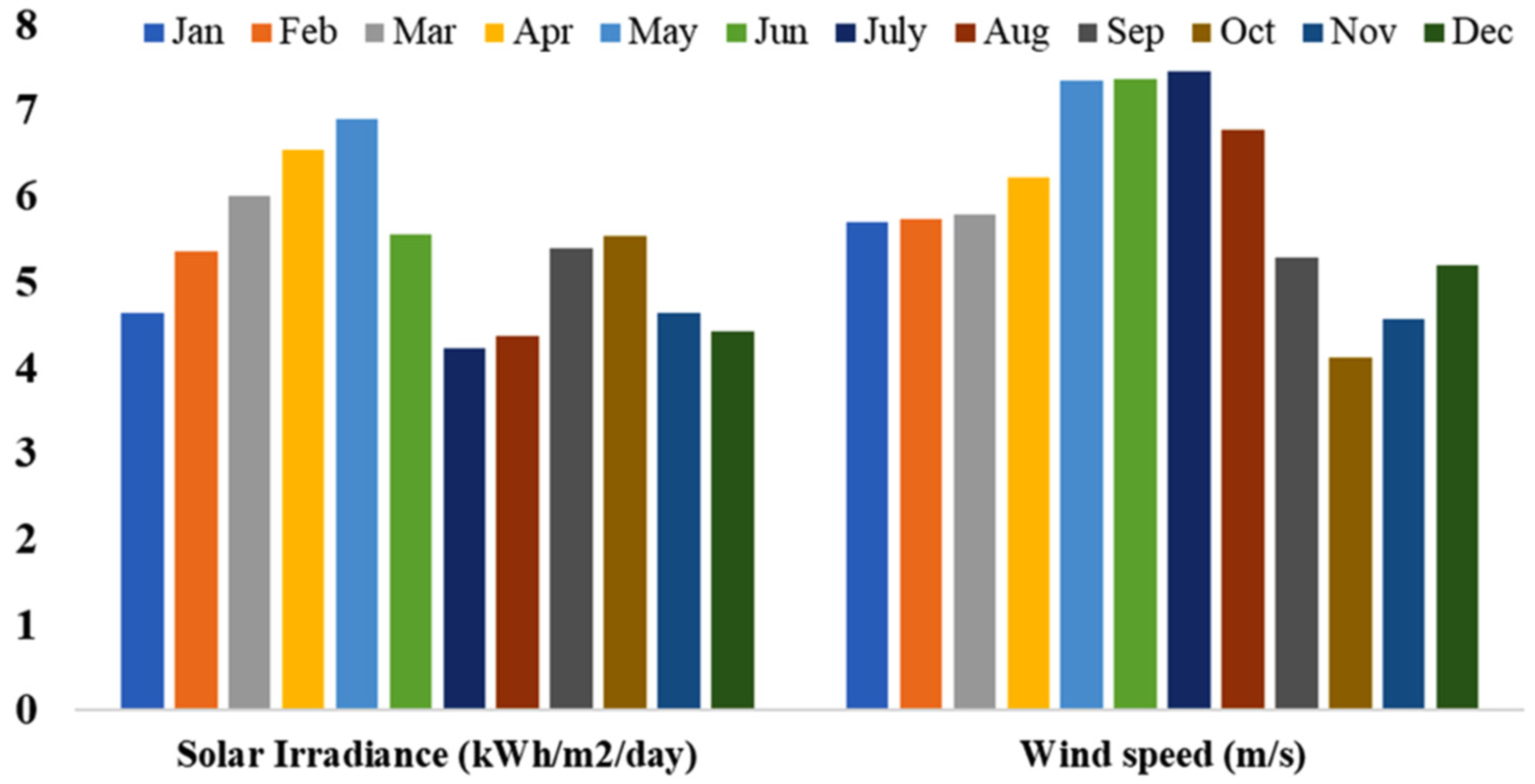
2.2. Description of Solar and Wind Potentials in the Surat Region

Accurate evaluation of renewable energy potential holds immense significance for maximizing power generation, particularly in countries such as India, which possess extensive land resources suitable for renewable energy installations. The efficacy of WT and SPV systems in India heavily relies on local wind speeds and solar irradiance respectively. Data on solar irradiance, and wind speed, for the selected site in India, sourced from NASA’s POWER directory, are elaborated in Figure 4. The average solar irradiance and wind speed data for different months of the year are shown in Figure 4, indicating that May witnesses the maximum solar irradiance, while December records the minimum, with an annual average of 5.29 kWh/m² per day. On the other hand, July and October exhibit the maximum and minimum values of the wind speed, respectively, with an annual mean wind speed of 5.96 m/s. These climatic parameters—solar irradiance and wind speed, are critical for the strategic planning and execution of renewable energy initiatives, predominantly in supporting the load demands of the PEV charging station in Surat. This comprehensive comprehension of local RESs is essential for devising efficient and sustainable energy solutions aligned with India’s broader environmental and developmental aspirations.

3. Mathematical Modeling of Hybrid Energy System

In this section, a comprehensive depiction of the proposed HES is provided, accompanied by mathematical modeling.

3.1. Solar Photovoltaic

The electrical power output produced by an SPV module is contingent upon various factors such as solar irradiance, ambient temperature, and module efficiency. Since solar irradiance and ambient temperature fluctuate over time, Equation (1) is employed to compute the SPV module’s electrical output power, denoted as E P S P V t [45].
E P S P V t = S I ( t ) × a S P V × η S P V
where E P S P V t is the electrical output power of the SPV module, S I ( t ) is the solar irradiance at time instant t , a S P V is the effective area of the SPV panel, and η S P V is the actual efficiency of the SPV panel.
Normally, the efficiency of SPV panels tends to be modest, typically falling within the range of 15% to 30%. This efficiency is influenced by the operational temperature of the SPV module, which itself is dependent on the ambient temperature. Equation (2) determines the actual efficiency of the SPV panel ( η S P V ), while Equation (3) calculates the actual operating temperature of the SPV module ( T o p ) [45].
η S P V = η m a x × η M P P T × 1 δ t T o p t T r a t e d
T o p t = T a m b t + N O C T T a m b , N O C T S I N O C T × S I ( t )
where η m a x and η M P P T represent the maximum efficiency of the SPV cell and efficiency at the operating point of MPPT, respectively, δ t denotes the temperature coefficient, T o p t and T r a t e d signify the actual operating temperature and maximum temperature of the SPV module, respectively, N O C T denotes the Nominal Operating Cell Temperature, T a m b t is the ambient temperature, T a m b , N O C T is the ambient temperature at NOCT, and S I N O C T is the solar irradiance at NOCT.

3.2. Wind Energy

The electrical power generated by a WT is contingent upon the wind speed and the efficiency of the turbine. As wind speed varies over time, the output power becomes a function of time. Equation (4) is employed to compute the output power of the wind farm ( E P W T t ) [46].
E P W T t = P W T G ( t ) × a W T × η W T
where E P W T t is the electrical power output of the wind farm, P W T G ( t ) signifies the mechanical output power of WT, a W T represents the area of the wind farm, and η W T is the efficiency of the WT.
The mechanical power output of the WT can be computed using Equation (5).
P W T G =   0                                                         V W T V c i     b × V W T 3 c × P W T r a t e d                 V c i <   V W T < V r a t e d             P W T r a t e d                                                                                   V r a t e d <   V W T < V c o   0                                                               V W T V c o  
where V W T represents the wind speed at a specific height, while V c i and V c o represent the cut-in and cut-off speeds, respectively. P W T r a t e d refers to the rated power of the WT, and V r a t e d represents the rated wind speed. b and c are the WT constants.

3.3. Battery Energy Storage

In HES incorporating renewable sources, batteries serve as crucial energy storage components to counteract their intermittent nature. Nonetheless, batteries often present various drawbacks, such as high initial costs, limited lifespan, and constrained power capacity. The electrical energy stored in the batteries at time t ( E B E S t ) can be computed using Equation (6) [47].
E B E S t = E B E S t 1 × 1 ƛ + P B E S t × t
where E B E S t is the electrical energy stored in BES at time instant t , P B E S t denotes the electrical power charged/discharged into/from the BES, and ƛ represents the self-discharge rate of BES.
To ensure the optimal functioning of the BES, it is imperative to maintain a minimum level of stored energy within the battery bank to safeguard against over-discharge, thereby preserving its longevity. This minimum battery energy ( E B E S , m i n ) is contingent upon both the maximum depth-of-discharge ( D O D m a x ) and the overall energy capacity of the battery bank ( E B E S , c a p ). Equation (7) computes ( E B E S , m i n ) [47].
E B E S , m i n = 1 D O D m a x × E B E S , c a p

3.4. Bi-Directional Inverter

The bidirectional converter serves a pivotal function in ensuring the effective transfer of power within the system. It facilitates the conversion of DC power sourced from batteries or renewable energy systems into AC power for consumption, and conversely, it handles excess AC power by converting it back to DC. When determining the size of an inverter, two key power measurement parameters are taken into account: continuous power, which indicates the inverter’s capability to manage a sustained load, and rated power, which signifies the inverter’s ability to withstand short-term power spikes. The operational efficiency of a bidirectional inverter can be mathematically expressed as follows [34].
η i n v = P i P i + P i n t + f P i 2
where P i , P i n t , and f , respectively, can be given as follows:
P i = P o u t P n
P i n t = 1 99 10 η 10 1 η 100 9 2
f = 1 η 100 P i n t
where η 10 and η 100 represents the efficiency of 10% and 100% of nominal power.

3.5. Utility Grid

Within a grid-connected HES, the grid functions under two distinct modes. In the first mode, it provides additional electricity to the HES when the RES, coupled with the BES, is unable to fulfill the demand. Mathematically, the grid-purchased energy can be represented as [48].
P P u r c h a s e g r i d t = P D P E V t E P R E S t + E P S P V t + E B E S , c a p ( t ) E B E S , m i n ( t ) × η i n v
In the second mode of operation, when PEV demand for electricity is less than RES power generation, the extra electricity is sold to the grid operator. This can be mathematically depicted using Equation (13).
P S o l d g r i d t = E P R E S t + E P S P V t E B E S , m a x ( t ) E B E S , c a p ( t ) × η i n v P D P E V t

4. Objective Functions, Constraints, and Energy Management Strategy

This analysis evaluates the optimization and performance of HES models by considering various determinant criteria across three domains: technical analysis, which includes annual power generation, economic analysis, which involves COE, TNPC, and operating and initial capital costs, and environmental factors, such as renewable fraction (RF), life cycle emission (LCE), and accessibility to renewable resources. It is crucial to explore the feasibility of selecting either a standalone PEV charging station or an on-grid PEV charging station from both technical and economic perspectives.

4.1. Objective Functions

4.1.1. Total Net Present Cost (TNPC)

The Total Net Present Cost (TNPC) serves as a key economic indicator frequently employed to assess the optimized design of systems involving diverse configurations. It encompasses factors such as initial costs, component replacements, operational expenses, and maintenance costs. TNPC offers robust reliability compared to metrics such as the Cost of Energy (COE), which can be somewhat arbitrary. The following formula is utilized to compute TNPC [13].
T N P C = C c a p + C r e p + C o m
The energy management system incorporates components such as the solar power system, wind generator, and storage unit. Each resource’s individual cost is taken into account to formulate the objective function. Equation (15) computes the capital cost of an SPV panel.
C c a p S P V = α S P V × A S P V
where C c a p S P V is the capital cost of the SPV panel and α S P V and A S P V represent the initial cost and area of the SPV system, respectively.
Equation (16) is employed to calculate the total expenditure necessary for the operation and maintenance of an SPV system.
C o m S P V = S P V × A S P V × n = 1 N 1 + e r 1 + i r n
where S P V represents the annual cost of maintaining and operating the SPV system, e r denotes the escalation rate, i r represents the interest rate, and n represents the lifespan of the project.
The replacement cost of the SPV system depends on the number of SPV panels ( N S P V ), cost of replacement of each SPV unit ( C S P V r e p ), and interest rate ( i r ), and can be calculated using Equation (17).
C r e p S P V = N S P V × c r e p S P V × n = 1 N 1 1 + i r N × L
Another significant source is the wind energy system, which is integrated into the system’s modeling. The capital cost of the wind energy system is determined using Equation (18).
C c a p W T = α W T × A W T
where C c a p W T is the capital cost of the WT panel and α W T and A W T represent the initial cost and area of WT, respectively.
The operation and maintenance costs of WT systems can be computed using Equation (19).
C o m W T = W T × A W T × n = 1 N 1 + e r 1 + i r n
where W T represents the annual cost of maintaining and operating a WT system.
The replacement cost of WT systems can be computed using Equation (20).
C r e p W T = N W T × c r e p W T × n = 1 N 1 1 + i r N × L
where c r e p W T is the cost of replacement of each WT unit and N W T denotes the number of WT.
BES devices units play a vital role in energy modeling, offering reliability in power supply. The capital cost of the integrated BES is determined as follows:
C c a p B E S = α B E S × P B E S
where C c a p B E S is the capital cost of BES, and α B E S and P B E S represent the initial cost and power rating of the BES device, respectively.
The operation and maintenance cost of the BES device can be computed using Equation (22).
C o m B E S = B E S × N B E S × n = 1 N 1 + e r 1 + i r n
where B E S represents the annual cost of maintaining and operating a WT system and N B E S denotes the number of BESs.
The replacement cost of the BES device can be computed using Equation (23).
C r e p B E S = N B E S × c r e p B E S × n = 1 N 1 1 + i r N × L
where c r e p B E S is the cost of replacement of each BES unit.
The inverter or converter within the electrical system transforms AC to DC and vice versa. Equations (24)–(26) compute the initial cost, operation and maintenance cost, and replacement cost of the inverter.
C c a p i n v = α i n v × P i n v
where C c a p i n v is the capital cost of BES and α i n v and P i n v represent the initial cost and power rating of the inverter, respectively.
C o m i n v = i n v × P i n v × n = 1 N 1 + e r 1 + i r n
C r e p i n v = N i n v × c r e p i n v × n = 1 N 1 1 + i r N × L
In the case of a grid-tied system, the calculation of the cost for selling and purchasing power to and from the grid can be computed using Equations (27) and (28), respectively.
C s g r i d = ξ s g r i d × E s g r i d × 1 + e r 1 + i r n
C p g r i d = ξ p g r i d × E p g r i d × 1 + e r 1 + i r n
where ξ s g r i d and ξ p g r i d represent the unit cost for selling and purchasing electricity to and from the utility grid, respectively.

4.1.2. Cost of Energy (COE)

The energy cost stands out as a pivotal factor in determining the economic feasibility of HES. It is derived from the lifetime average net present cost associated with renewable energy. TNPC serves as a crucial metric for evaluating the expenses of various energy systems, encompassing operation and maintenance, capital, and replacement costs. Hybrid RESs, devoid of fuel requirements, boast economical operational and maintenance expenses owing to their ecological advantages [49]. The COE is represented as the per-unit cost of generated electricity (USD/kWh) and is computed using a specific formula.
L C O E = N P C t = 1 8760 P D P E V ( t ) × C R F
C R F = i r × 1 + i r n 1 + i r n 1
It is assumed that prices increase uniformly, and annual interest rates are employed instead of nominal interest rates.

4.1.3. Life Cycle Emission (LCE)

Assessing ecological sustainability involves evaluating the overall greenhouse gas emissions originating from an energy facility. These emissions encompass CO2, SO2, NO, and other pollutants detrimental to the environment, affecting both human beings and wildlife. This paper calculates the Life Cycle Emissions (LCE), which represent the equivalent CO2 emissions resulting from the energy consumed in manufacturing, transporting, recycling system components, and operational activities [50]. These emissions are quantified in kilograms of CO2-equivalent per year. The mathematical expression for computing LCE is as follows:
L C E = b = 1 B β b E L
where B denotes the number of components of the energy system, β b is the lifetime equivalent CO2 emissions of each component, and E L is the energy generated by each system component. The lifetime equivalent CO2 emissions of each component are provided in Table 2.

4.2. Operational Constraints

4.2.1. Reliability Constraint

To guarantee a dependable power provision to the load, the HES must meet reliability standards. The primary parameter indicating reliability is the Loss of Power Supply Probability (LPSP), which is defined as follows:
L P S P L P S P m a x
where L P S P m a x denotes the upper threshold of system reliability tolerance.

4.2.2. BES Constraint

Maintaining the State of Charge (SOC) of the BES within specified minimum and maximum thresholds is crucial. This prevents the BES from being either fully charged or fully discharged, thus prolonging its lifespan, considering that BES components typically have the shortest lifespan. Moreover, BES units are expensive and necessitate frequent maintenance. Integrating BES into hybrid systems for storage helps balance the electricity demand and supply.
S O C m i n S O C S O C m a x

4.2.3. Balancing in Power

Sustaining reliability in the electrical system requires ensuring that total power consumption matches total power generation. This means that the electricity delivered by the RES, and grid should equal the power utilized by the load, plus the energy stored into the BES and any excess power discharged. The fluctuating behavior of SPV and WT, as well as the storage system’s charge and discharge rates, make it difficult to achieve perfect energy balance throughout each period. The condition is stated as follows:
E P S P V t + E P W T t + P P u r c h a s e g r i d t = P D P E V t + P S o l d g r i d t + P B E S , d i s + P d u m p

4.2.4. Restriction on Decision Variables

The decision variables that influence the best possible layout of an integrated system are chosen via an optimization procedure. All of these variables have relationships to different components of the system [51].
N S P V m i n N S P V N S P V m a x
N W T m i n N W T N W T m a x
N B E S m i n N B E S N B E S m a x
where N S P V m i n and N S P V m a x , N W T m i n and N W T m a x , and N B E S m i n and N B E S m a x represent the minimum and maximum quantities of SPV panels, WT, and BES devices, respectively.

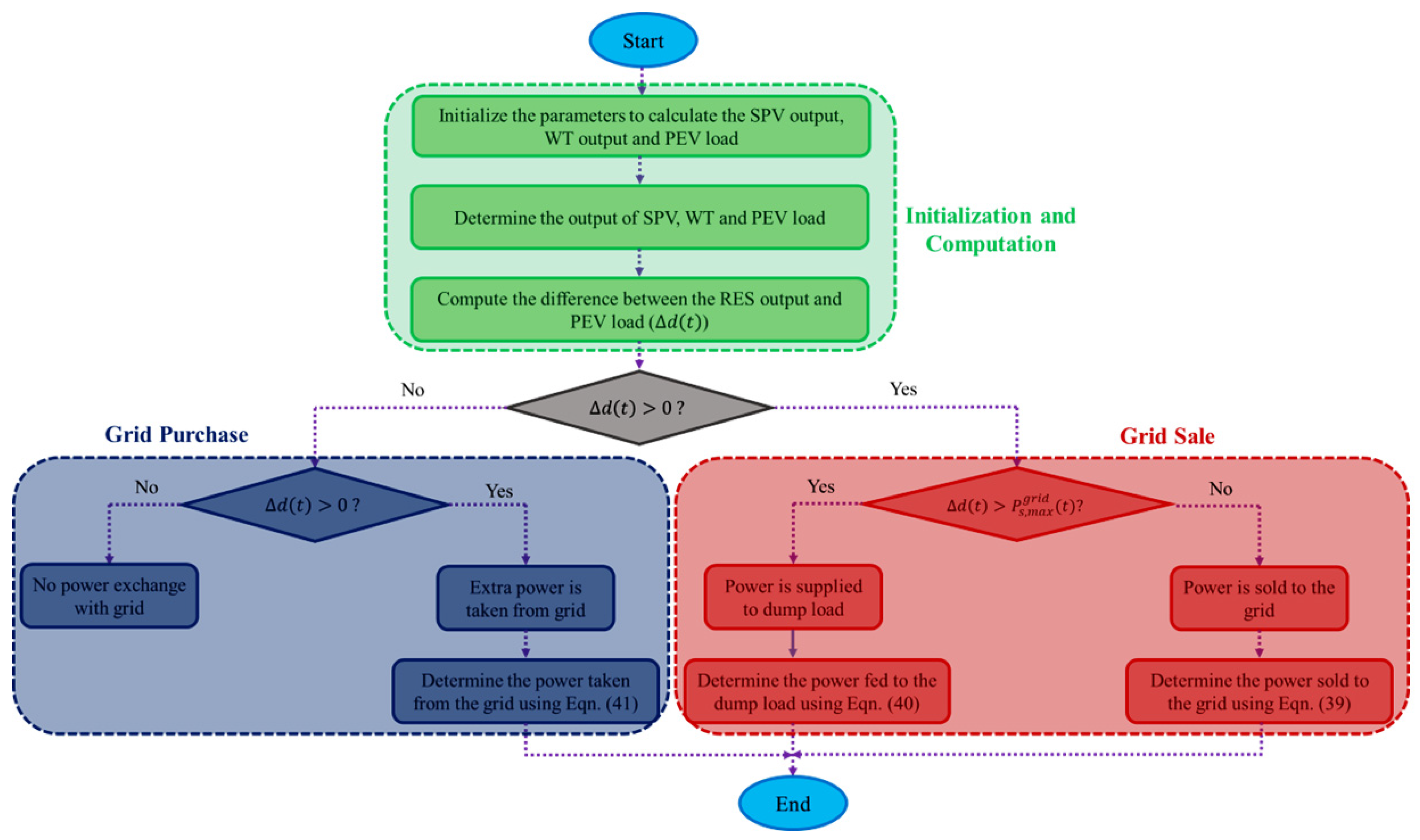
4.3. Energy Management Strategy

The goal of this research is to meet the demand for PEV load in the Surat region, India, using two main RES: solar and wind energy. The difference between the power generated by RES and the PEV load can be expressed as follows:
d t = E P S P V t + E P W T t P D P E V t
In situations where the power generated by RES is insufficient, any shortfall is compensated by drawing power from the grid. Conversely, if there is an excess of power from RES beyond the load requirements, it is supplied back to the grid. However, constraints on grid transactions exist, defined as the maximum allowable grid purchase and the maximum grid selling capacity. Transactions exceeding these limits, whether borrowing or selling, are prohibited. The following scenarios can be facilitated based on the d t .
  • When d t exceeds zero, it indicates that the total power generated by RES is sufficient for charging PEVs. Moreover, any surplus power is identified to be sold to the grid, which can be expressed in Equation (34):
( P s g r i d ( t ) ) = E P S P V t + E P W T t P D P E V t / η i n v
  • When the output from RES is ample to meet the energy requirements of PEV loads and exceeds the maximum selling capacity of the electric network, the surplus electric power is diverted to the dump load. The calculation for this surplus can be articulated as follows:
P d u m p ( t ) = E P S P V t + E P W T t P D P E V t P s , m a x g r i d ( t ) / η i n v )
  • If d t < 0 , it indicates that the power generated by the renewable components is insufficient to meet the load demand of PEVs. Therefore, the necessary electric power is obtained from the national grid, as detailed below:
( P p g r i d t ) = ( P D P E V t E P S P V t E P W T t ) / η i n v
  • If d t = 0 , no power exchange occurs with the grid, and the energy demands of PEVs are met solely by the power generated from SPV and WT systems;
  • If the collective output of RES and grid power is insufficient to fulfill the peak load demand, it results in a power deficit, which can be depicted as the combined output of RES and grid power falls short of meeting the peak load demand, a power deficiency emerges which can be represented as follows:
P d e f t = P p g r i d t P p , m a x g r i d t
The steps involved in the energy management strategy of on-grid and RES-based charging of PEVs are displayed in Figure 5.

4.4. Current Energy Grid

The current energy grid in the Surat region, located in the state of Gujarat, India, is a robust network designed to meet the high energy demands of its industrial and urban sectors. The grid’s maximum capacity to cover energy shortfalls, particularly when renewable energy sources are insufficient, is approximately 2.5 GW. This capacity ensures that the region can maintain stability and reliability during periods of low renewable energy generation, such as cloudy days for solar or calm periods for wind power. The actual installed power capacity in Surat is around 2 GW, with a significant portion coming from a mix of thermal power plants and an increasing share from renewable sources such as solar and wind energy. The region has made substantial investments in renewable energy, with solar power installations contributing approximately 500 MW and wind power around 300 MW. Looking forward, Surat is expected to see its installed power capacity increase to 3.5 GW by 2030, driven by further investments in renewable energy projects and grid modernization efforts. This projected growth includes an additional 1 GW from solar power and 500 MW from wind energy, reflecting the region’s commitment to sustainable energy solutions and reducing dependence on fossil fuels. These expansions and enhancements are crucial for ensuring energy security, economic growth, and environmental sustainability in the Surat region.

5. Pufferfish Optimization Algorithm

The subsequent segment delineates the concept of the Pufferfish Optimization Algorithm method, along with a mathematical exposition of its utilization in addressing optimization challenges.

5.1. Initialization of POA

The suggested POA approach efficiently addresses optimization challenges by employing demographic search iteratively. In this process, every POA member computes the values of selection variables pertinent to its position within the search space. Each POA member embodies a prospective solution to the problem and can be represented mathematically as a vector comprising decision variables. These members collectively form the population of the algorithm. Equation (43) illustrates the utilization of a matrix for modeling a set of vectors. Equation (44) establishes the initial position of each POA member at the algorithm’s onset.
Y = Y 1 Y i Y M M × m = y 1,1   .   y i , 1 y M , 1 .   .     .         .     y 1 , d   .   y i , d     y M , d                   y 1 , m     .     y i , m     .     y M , m M × m
y i , d = L B d + r a n d × U B d L B d
In this context, Y represents the matrix of the POA population, Y i denotes the ith POA member (candidate solution), and y i , d signifies its d t h dimension within the search space (decision variable). M stands for the total number of population members, while m represents the count of decision variables. The variable r a n d denotes a random number within the range [0, 1], and L B d and U B d denote the lower and upper bounds of the d t h decision variable, respectively.
Using each POA component as a potential solution, the objective function of the problem can be assessed. Equation (45) outlines the method for representing a set of examined results for the objective function of the problem as a vector.
F = F 1 F i F M M × 1 = F Y 1 F Y i F Y M M × 1
where F represents the vector comprising the estimated objective function and F i stands for the estimated objective function corresponding to the i t h POA member.
The evaluated values of the objective function serve as suitable criteria for evaluating the quality of potential solutions provided by each POA member. The optimal value of the objective function corresponds to the best candidate solution, while its lowest value is linked to the poorest member. Since the positions of POA members in the problem-solving space alter with each iteration, it is crucial to update the most appropriate member based on newly evaluated values for the objective function.

5.2. Mathematical Modelling of POA

In the development of the proposed POA method, the adjustment of population members’ positions in the problem-solving domain is guided by simulating natural interactions between pufferfish and its predators. This emulation mirrors the sequence in nature where the predator initially targets the pufferfish, prompting the pufferfish to deploy its defense mechanism by forming into a sphere adorned with sharp spines, thereby deterring and evading the predator. Consequently, in each iteration, the positioning of POA population members undergoes two phases of adaptation: (i) exploration, mimicking the predator’s assault on the pufferfish, and (ii) exploitation, simulating the pufferfish’s defensive response against the predator.

5.2.1. Phase 1: Predator Attack Towards Pufferfish (Exploration Phase)

During the initial phase of POA, the adjustment of population members’ positions is influenced by emulating the predatory strategy aimed at the pufferfish. Due to their sluggish movement, pufferfish are susceptible targets for ravenous predators. By simulating the predator’s movement during its attack on the pufferfish, the position of POA members in the problem-solving space is updated. This modeling of the predator’s approach toward the pufferfish induces significant shifts in the positions of POA members, consequently enhancing the algorithm’s exploratory capabilities for global search.
In the POA framework, each population member is regarded as a predator, with the position of other population members possessing superior objective function values being considered as potential prey positions for attack. The group of potential prey for each population member is determined using Equation (46).
C P i = Y k : F k < F i   a n d   k i , w h e r e i = 1,2 , 3 . N   a n d   k ϵ 1,2 , 3 N
where C P i represents the collection of potential locations of candidate pufferfish for the i t h predator, Y k denotes the population member with a superior objective function value compared to the i t h predator, and F k represents its corresponding objective function value.
In the POA framework, it is posited that the predator randomly selects one pufferfish from the candidate pufferfish locations identified in the C P set, which is then designated as the selected pufferfish (SP). Following the emulation of the predator’s movement toward the pufferfish, a fresh position within the problem-solving space is computed for each POA member using Equation (47). Subsequently, if an improvement is observed in the objective function value at the new position, this revised position supplants the previous one for the respective member in accordance with Equation (48).
y i , j p 1 = y i , j + r a n d i , j × S P i , j J i , j y i , j
Y i = Y i p 1       F i p 1 < F i Y i       else
where S P i denotes the pufferfish chosen randomly for the i t h predator from the C P i set, while S P i , j represents its j t h dimension. Y i p 1 signifies the newly computed position for the i t h predator derived from the first phase of the proposed POA, and y i , j p 1 denotes its j t h dimension. F i p 1 stands for its objective function value, r a n d i , j represents random numbers selected from the range [0, 1], and J i , j signifies numbers randomly chosen as either 1 or 2.

5.2.2. Phase 2: Defense Mechanism of Pufferfish against Predators (Exploitation Phase)

During the second phase of POA, adjustments to population members’ positions are made by simulating a pufferfish’s defense mechanism against predator attacks. When a predator targets a pufferfish, the pufferfish inflates its highly elastic stomach with water, transforming into a spherical form adorned with sharp spines. This defensive posture acts as a deterrent, causing the predator to retreat from the pufferfish’s vicinity instead of pursuing an easy meal. The simulation of the predator’s withdrawal from the pufferfish results in minor alterations to the positions of POA members, thereby enhancing the algorithm’s exploitative capabilities for local search.
Following the modeling of the predator’s movement away from the pufferfish, a fresh position is computed for each POA member using Equation (49). Subsequently, if this new position leads to an improvement in the objective function value, it replaces the previous position for the corresponding member in accordance with Equation (50).
Equation (50) is employed in the POA design to enhance the algorithm’s effectiveness. Essentially, when a new position is calculated for a POA member, its suitability is determined by comparing objective function values. If the new position yields a superior solution to the problem, it is deemed acceptable for the corresponding POA member. Conversely, if the new position results in a weaker solution, the member retains its previous position. Thus, Equation (50) signifies that the update process for each POA member is contingent upon enhancing the objective function value.
y i , j p 2 = y i , j + 1 2 × r a n d i , j × U B j L B j t
Y i = Y i p 2       F i p 2 < F i Y i       else
where Y i p 2 represents the newly computed position for the i t h predator derived from the second phase of the proposed POA, with y i , j p 2 representing its j t h dimension. F i p 2 denotes its objective function value, while r a n d i , j signifies random numbers selected from the interval [0, 1], and t indicates the iteration count.

5.3. Repetition Process and Flowchart of POA

After updating the positions of all POA members according to the exploration and exploitation phases, the initial iteration of the algorithm concludes. Subsequently, the algorithm proceeds to the next iteration, where the process of position updating for POA members continues using Equations (45)–(50) until the final iteration is reached. Within each iteration, the position of the top-performing POA member is revised and retained based on the comparison of objective function evaluations. Upon the completion of the algorithm’s full execution, the position of the best-performing POA member is identified and presented as the solution to the problem.
The steps for implementing POA are illustrated in a flowchart depicted in Figure 6.

5.4. Implementation of the Proposed POA for Designing SPV/WT/Grid-Based PEV Charging Stations

The implementation of the proposed POA for designing SPV, WT, and grid-based PEV charging stations involves several key steps to ensure efficiency, cost-effectiveness, and sustainability. The optimization techniques employed in this work follow a systematic process, which can be divided into two main stages.
Stage 1 focuses on creating the suggested hybrid energy system based on energy balancing, which involves three major steps. First, the initial population is created, representing different configurations of the hybrid system. Second, the hybrid system is developed using Equations (1)–(13), which likely include the mathematical models for energy production, consumption, and integration of SPV, WT, and grid resources. Third, the fitness function is assessed for all agents/positions using Equation (29), which evaluates the performance of each configuration based on criteria such as cost of energy and sustainability.
Stage 2 involves executing the optimization algorithm with the hybrid system, encompassing the following procedures. First, the sizing of system components is adjusted in accordance with the optimization algorithm to find the most efficient and cost-effective configuration. Second, the proposed system is constructed again using Equations (1)–(13) to reflect these adjustments. Third, the fitness function is reassessed for all agents/positions using Equation (29) to ensure the updated configurations meet the desired performance criteria. Finally, the termination criterion is verified. If the criterion is not satisfied, the process iterates through the preceding three steps, adjusting component sizes, reconstructing the system, and reassessing the fitness function, until an optimal solution is achieved.
This iterative process ensures that the design of SPV, WT, and grid-based PEV charging stations is continuously refined to maximize efficiency, cost-effectiveness, and sustainability, leveraging the robust capabilities of the POA.

6. Simulation Outcomes and Discussions

This study seeks to conduct a technical and economic assessment of on-grid charging of PEVs integrated with RESs in Surat, India. The focus is on leveraging the abundant RES deposits and existing power infrastructure in the area. Existing literature employs various optimization techniques to size decision variables for meeting PEV load demands at minimal energy costs. This research optimized TNPC and COE using the Pufferfish Optimization Algorithm (POA), validating its efficacy against other methods such as Giza Pyramid Construction Algorithm (GPCA), Artificial Hummingbird Algorithm (AHA), Flower Pollination Algorithm (FPA), etc. Different system configurations combining RESs, storage devices, and the grid were designed, analyzed, and optimized for minimum electricity costs and TNPC. These configurations include SPV/BES, SPV/WT/BES, SPV/WT/Grid, SPV/Grid, and WT/Grid. Techno-economic variables for these configurations in Surat, India were examined, considering the intermittent nature of RESs and bidirectional electricity flow. The modeling of PEV load and optimization algorithms were implemented using MATLAB. Table 2 contains detailed technical and economic specifications. Performance indices such as COE, TNPC, component capacities, grid interactions, and sensitivity evaluations were analyzed. POA exhibited faster convergence and superior results across various LPSP levels compared to GPCA, AHA, and FPA.
Furthermore, an examination of various scenarios involving different levels of LPSP was conducted to assess their impact on TNPC and COE. Figure 7 depicts the convergence curve for both the proposed POA and other algorithms used for comparison. The computational time needed by POA was notably shorter, requiring fewer iterations to reach the optimal solution compared to GPCA, AHA, and FPA methods. The GPCA, AHA, and FPA each had distinct demerits when compared to the POA across various performance metrics. GPCA often exhibited a more gradual and less dynamic convergence curve, which could lead to slower convergence, particularly in complex problem spaces. Its deterministic and structured approach may also result in less robustness and longer execution times, as it may require more iterations to refine solutions. In contrast, POA’s dynamic exploration and exploitation strategies typically led to faster and more reliable convergence. AHA, while fast in local searches, tended to converge quickly to local optima, which could impede its ability to find global solutions. This characteristic can make AHA less robust compared to POA, which balances exploration with exploitation to avoid local optima. AHA’s reliance on intensive local search could also lead to inconsistent convergence speeds and execution times, whereas POA’s approach often ensured more stable and efficient performance. FPA’s convergence behavior can be affected by the balance between local and global pollination rates. If this balance is not well-tuned, FPA may experience slower and less stable convergence. Its execution time can be longer if the algorithm struggles to effectively balance exploration and exploitation. POA, on the other hand, provides a more consistent convergence curve and greater robustness due to its ability to adaptively manage exploration and exploitation, making it generally more reliable and efficient in finding high-quality solutions across varied optimization problems. Additionally, POA consistently delivered superior results across all levels of LPSP considered.

6.1. Performance Analysis of the Various Designs of PEV Charging Station

This section delves into the detailed examination of the PEV charging station system configurations using performance indicator parameters. Renewable energy systems exhibit significant electricity production fluctuations, leading to the adoption of backup supply systems such as BES and grid connectivity options to enhance reliability. Hence, this analysis explores potential system configurations for PEV charging, including SPV/BES, SPV/WT/BES, SPV/Grid, SPV/WT/Grid, and WT/Grid, all aimed at meeting PEV charging demand. Optimized results for these configurations, achieved through the POA technique, are presented in Table 3. Among these configurations, C3 (SPV/WT/Grid) stood out with the lowest TNPC of USD 2,22,762.80 and a COE of USD 0.022/kWh, indicating its desirability and cost-effectiveness.
This configuration, which integrates SPV, WT, and the power grid, effectively fulfills PEV charging requirements. Despite the intermittent nature of RESs, the grid serves as a backup, ensuring supply reliability. C3 purchased around 3902 kWh annually from the grid while exporting approximately 741,494 kWh/year, achieving a renewable penetration of 99.5%. Comparatively, C1 (SPV/BES) boasted a 100% renewable fraction, making it environmentally preferable. However, its high TNPC (USD 296,975.10) and COE (USD 0.8642/kWh) render it financially unviable for PEV charging. In C2, integrating SPV, WT, and a storage battery, the majority of energy production came from solar PV (97.1%), whereas WT contributed only 2.87% of the total PEV load demand satisfaction, yielding a renewable penetration of 100%. However, its high COE (USD 0.7632/kWh) and TNPC (USD 262,254.80) pose economic challenges. In C4, when SPV alone was integrated with the utility grid, the COE (USD 0.1150/kWh) improved as compared to C1 and C2 but TNPC (USD 283,615.1) increased to a higher value as compared to C2. Transitioning to C5, with WT replacing SPV, reduced COE and TNPC to USD 0.03/kWh and USD 247,177.40, respectively. The variation of TNPC and COE values obtained for various configurations is shown in Figure 8.
A comprehensive analysis of optimal configurations aimed at meeting the charging demands of PEVs in the Surat region is presented in Table 3. Among these configurations, it is evident that the SPV/WT/Grid setup, optimized using the POA, stood out with the lowest values for both the COE and TNPC. This superiority can be attributed to reduced costs associated with capital investment, equipment replacement, and ongoing operation and maintenance. Specifically, the optimized values for COE and TNPC achieved through POA were USD 0.022/kWh and USD 222,762.80, respectively. These numerical outcomes significantly surpassed the results obtained from other algorithms utilized in this study. For instance, the TNPC value estimated by POA was notably lower, with reductions of 37.1%, 54.3%, and 59.4% compared to calculations performed using the GPCA, AHA, and FPA, respectively. This comparative analysis is visually depicted in Figure 9. Similarly, POA yielded an optimized COE value of USD 0.022/kWh, showcasing reductions of 40.7.1%, 77.7%, and 79.2% compared to COE values determined by GPCA, AHA, and FPA, respectively. The variation in COE values across different existing algorithms is graphically represented in Figure 9. These findings underscore the effectiveness and efficiency of POA in achieving cost optimization for PEV charging configurations in the Surat region, thereby highlighting its potential for practical implementation and real-world application.

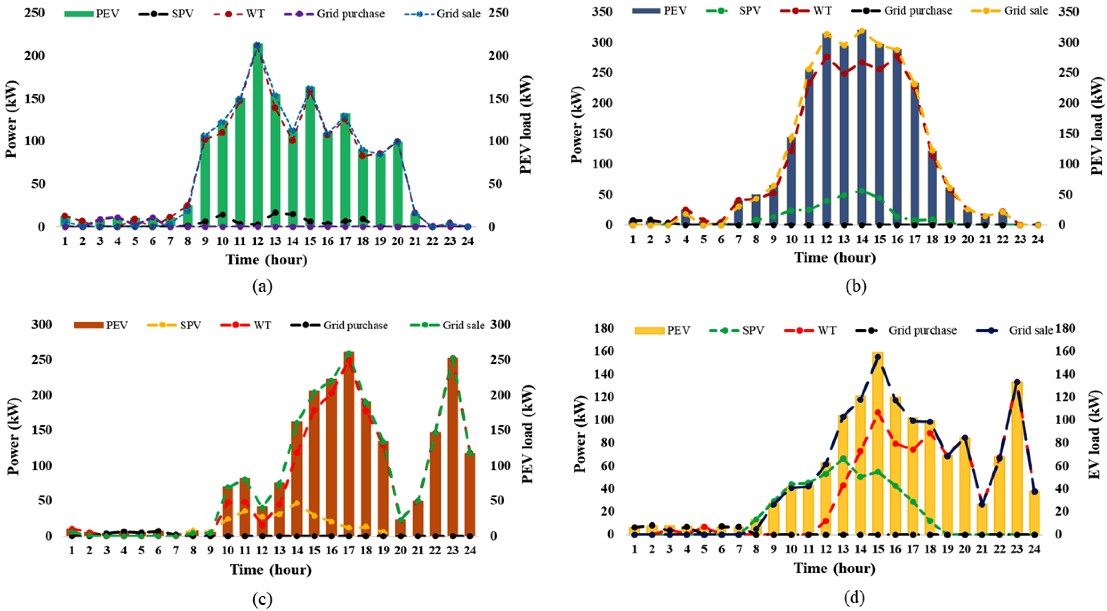
6.2. Analysis of Simulation Results for Different Weather Conditions

Figure 10 illustrates the 24-hour power production profiles of various energy components, including grid purchases, across the four meteorological seasons: winter, spring, summer, and autumn. The analysis of the graph indicated that power output from SPV and WT was generally lower between 12:00 AM and 6:00 AM in all seasons, except for an increase in wind power generation during the summer. The hourly simulation results for the different climate seasons are detailed further below:
Case #1: Winter Season
During the winter, the WT produced minimal electricity, and the solar output was negligible from 12:00 AM to 7:00 AM, insufficient to meet the PEV charging requirements. As a result, more energy was drawn from the grid to supplement the wind output and adequately meet the PEV charging load. During this period, the system experienced peak energy purchases from the electric power network, resulting in zero revenue for the PEV charging station operator, as no energy was supplied to the electric distribution network. After 7:00 AM, solar and wind output began to increase sufficiently to meet the majority of the charging requirements, with any excess energy exported to the power network whenever generation exceeds PEV load demand. Solar and wind output, as well as the amount of energy sold to the electricity network, peaked during the day, as indicated in Figure 10a. Consequently, the system required only a small amount of electricity from the electric network during this time, as shown in Figure 10a. This trend continued until 6:00 PM, when the system started to purchase a significant amount of electricity from the grid due to decreased power generation from the SPV and WT systems.
Case #2: Spring Season
During the spring season, the system recorded the lowest wind and solar power production in the first and last hours of the day, necessitating a moderately large amount of electricity imported from the electric distribution network to meet the PEV load, as illustrated in Figure 10b. Similar to the winter season (Case #1), the majority of solar and wind energy production occurred during the day. In this case, the output from solar and wind was sufficient to meet the PEV charging requirements, with excess power fed into the grid. A detailed look at Figure 10b reveals that a substantial amount of surplus energy was exported and sold to the electric network after meeting the PEV load demand, generating additional revenue for the charging system operator. During this time, very little electricity was drawn from the power grid.
Case #3: Summer Season
In the summer season, unlike Case #1 and Case #2 where maximum solar and wind power production occurred around midday, Figure 10c shows that peak solar and wind power production occurred at different times of the day. The WT generated its maximum power at the start of the day, as indicated by the red dashed line, while the solar PV generated most of its electricity during the day, as shown by the yellow dashed line in Figure 10c. In both instances, only a small amount of electricity was drawn from the electrical grid. However, power imports from the grid network increased slightly between 3:00 AM and 7:00 AM to meet the load demand. The graph also indicates that the system had excess energy after satisfying the load demand in the early morning and during the daytime due to substantial energy generation from renewable resources. In this scenario, the extra energy is sold to the electric grid at a favorable rate.
Case #4: Autumn Season
During the autumn season, the WT began producing energy after 6:00 AM and maintained a consistent output throughout the day, as indicated by the red dashed line in Figure 10d. Similar to the summer season (Case #3), most of the electricity drawn from the grid to supplement renewable sources for meeting PEV load occurred at the start and end of the day. The majority of solar power was generated during the middle of the day. The excess energy produced during this period, after meeting the PEV charge demand, was sold to the power network operator, as shown in Figure 10d, resulting in additional income for the PEV charging station operator.
Furthermore, the overall results of the power analysis for the optimal layout of PEV charging stations in Surat revealed that solar and wind systems were primarily responsible for meeting the PEV load. However, a significant amount of energy was drawn from the grid during periods of low or negligible wind and solar energy generation. Additionally, a substantial amount of surplus electricity, generated when renewable power exceeded PEV load demand, was sold to the electric network at a premium, benefiting PEV charging station owners.

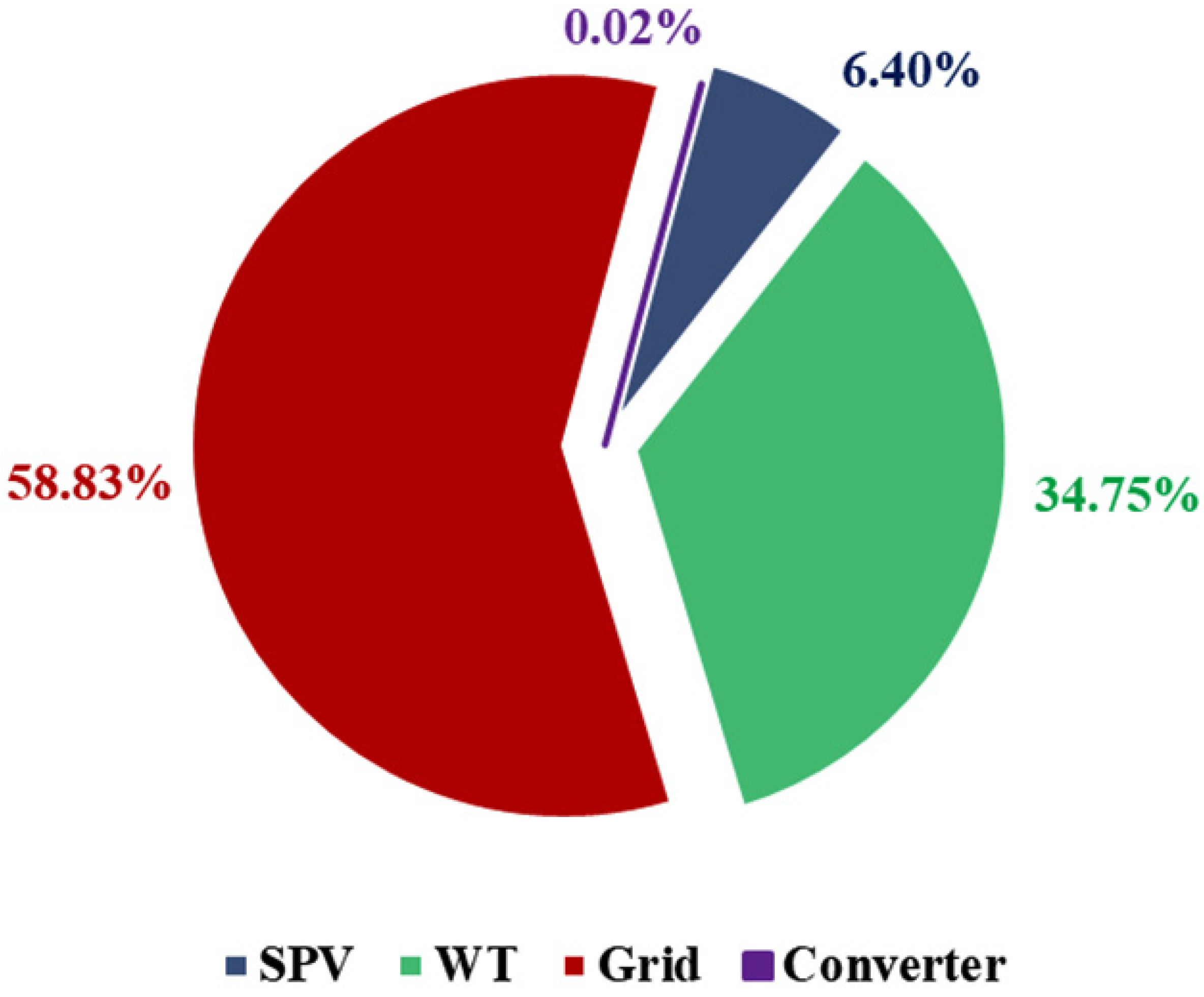
6.3. Energy Output by System Components

Despite the considerable electricity generation from SPV panels and WT, the converter’s output for the system remained relatively low. Specifically, the increase in power generation amounted to just 174 kWh per year, which is only 0.02% of the total energy produced. Even with a maximum annual capacity deficit of 0%, meaning the system theoretically meets all energy demands, the simulation model confirmed that there were no unmet loads. Figure 11 details the energy output from various system components. The SPV modules contributed 16.3% to satisfying the load demand, while the WT supplied a substantial 83.2%. Additionally, 0.5% of the energy was borrowed from the grid to ensure consistent supply. The system generated an extra 174 kWh per year, accounting for 0.022% of the total energy production. This extra energy, primarily generated by PEVs, comprised 96.5% of the total energy generation. The surplus energy from PEVs was sold back to the grid, providing a profitable opportunity for PEV owners, as they receive substantial fees from the grid operator for their excess electricity. Seasonal variations also impacted the energy generation profile. During summer, frequent rainfall and cloudy conditions reduced the power output from SPV arrays compared to the winter months. This seasonal fluctuation underscores the importance of having a diverse energy generation portfolio. Overall, implementing a grid-connected energy system proved to be more advantageous both technically and financially compared to relying solely on RESs. A grid-tied system ensures a reliable power supply by compensating for the variability in renewable energy generation and allows for the profitable sale of surplus energy, thereby enhancing the system’s economic viability.

6.4. Cost-Wise Breakdown of System Component

The cost breakdown of the main components in the SPV/WT/grid system is illustrated in Figure 12. The majority of the expenses are attributed to the SPV modules and WT. Due to the high replacement costs of the SPV and WT within the project, the investment cost is lower than the resource cost. This cost structure necessitates regular financial infusions for the integrated energy system to operate effectively. Consequently, this HES requires ongoing economic support to function properly. The proportion of energy derived from renewable sources is 0.995, indicating that RESs generate nearly all the energy needed to meet the load demand. This high reliance on renewables highlights their critical role in the system’s energy production.
For C3 (ideal configuration), the capital cost emerged as the largest component of the TNPC. Specifically, SPV and WT systems made substantial contributions, accounting for approximately 15.8% and 84.1% of the total capital cost, respectively. This significant investment in SPV and WT highlights the emphasis on RESs within this configuration. The grid network plays a crucial role in the operation and maintenance (O&M) costs, accounting for around 95.2% of the overall O&M expenses. This high percentage underscores the importance of maintaining the grid infrastructure to ensure reliable energy distribution. In contrast, the converter’s contribution to the O&M costs was relatively minor, at only about 0.06%. A notable feature of this configuration is the zero replacement costs reported for both the SPV and distribution grid components. Moreover, there were no recorded expenditures on fuel resources thanks to the exclusion of a DG from this system setup. This lack of reliance on fossil fuels further enhances the system’s sustainability and cost-effectiveness. When compared to other viable setups, this ideal configuration stands out due to its remarkably low TNPC value of USD 222,762.80. This low TNPC value reflects the system’s efficiency and the strategic allocation of resources towards capital investments in renewable energy technologies, minimal O&M costs for converters, and the elimination of fuel costs. This financial efficiency, combined with the environmental benefits of a predominantly renewable energy system, underscores the superiority of this configuration over other potential setups.

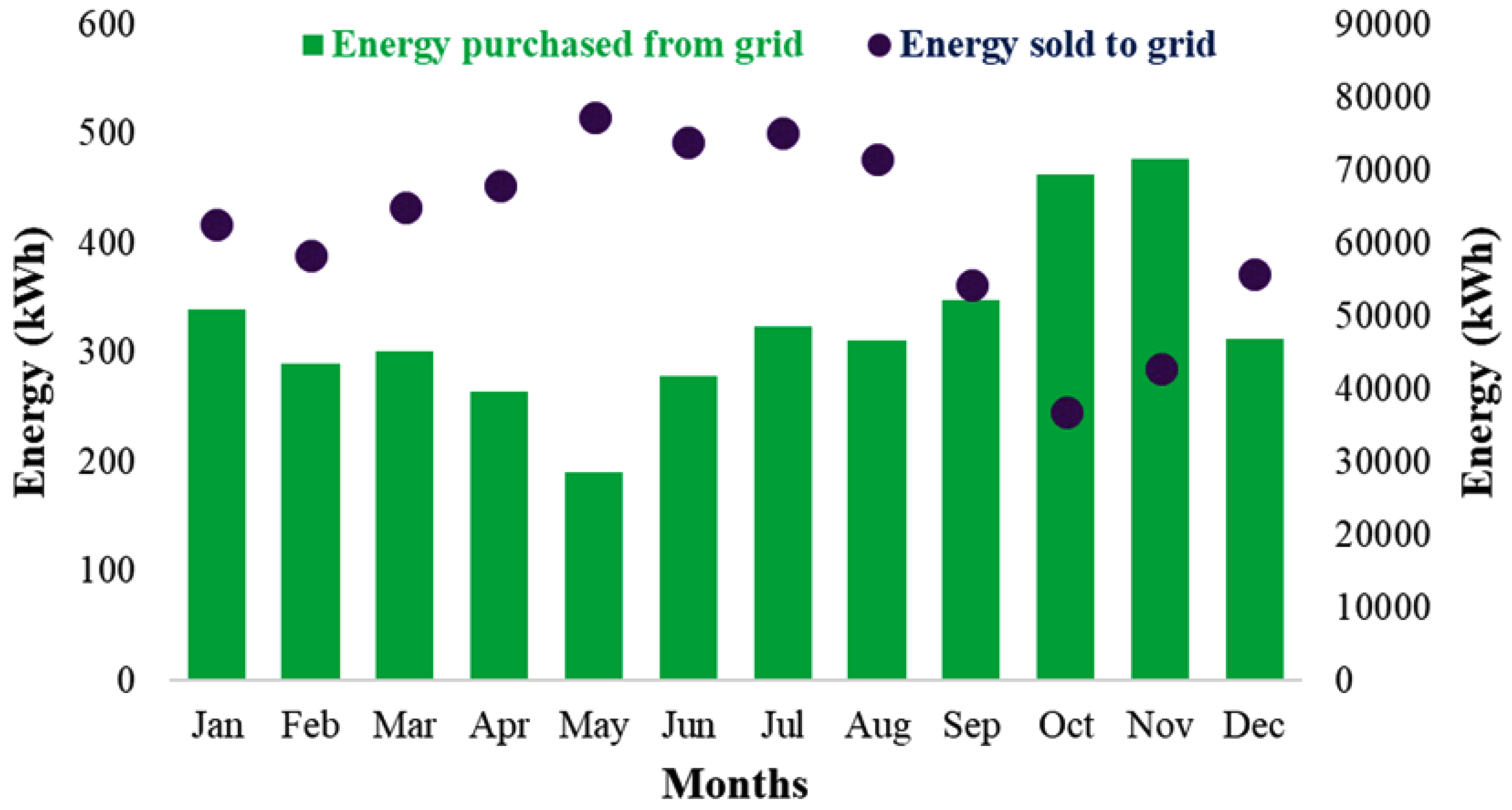
6.5. Monthly Grid Power Purchase and Sale

Figure 13 illustrates the monthly exchange of electricity with the distribution grid, revealing key insights into the system’s energy dynamics throughout the year. After consistently meeting the load requirements, the system managed to generate a significant surplus of energy on a monthly basis. This surplus was particularly notable from March to September, a period during which the excess power generated was substantial enough to be sold back to the electric network. This sale of surplus energy not only ensured the efficient utilization of generated power but also created additional revenue streams for the system operator, enhancing the economic viability of the system. The data highlights that the highest amount of surplus energy sold to the grid occurred in May, with a recorded sale of 77,305 kWh. In contrast, the lowest sale was observed in October, amounting to 36,851 kWh. These figures suggest a seasonal variation in surplus energy production, likely influenced by factors such as solar intensity and wind patterns affecting the SPV and WT outputs. On the other hand, the system also experienced periods where it needed to draw electricity from the grid due to insufficient renewable energy generation. This dependency on grid power was most pronounced in October and November, reflecting the seasonal dip in renewable energy availability. The highest grid purchase occurred in November, with 477 kWh, and the lowest in May, with 191 kWh. These fluctuations indicate a reliance on the grid during months with lower renewable energy production, contrasting with the self-sufficiency achieved during the surplus months. Furthermore, the minimum grid imports were recorded in April and May, correlating with the peak performance of the SPV and WT systems. During these months, the renewable energy generated was sufficient to meet the load requirements, significantly reducing the need for external electricity. Overall, the results underscore the advantages of a grid-tied renewable energy system. By balancing between generating surplus power for sale and drawing from the grid, when necessary, such a system proves to be both technologically efficient and economically beneficial. This dual capability ensures a more reliable and cost-effective energy solution compared to relying solely on renewable resources, which may be subject to variability and inconsistency.

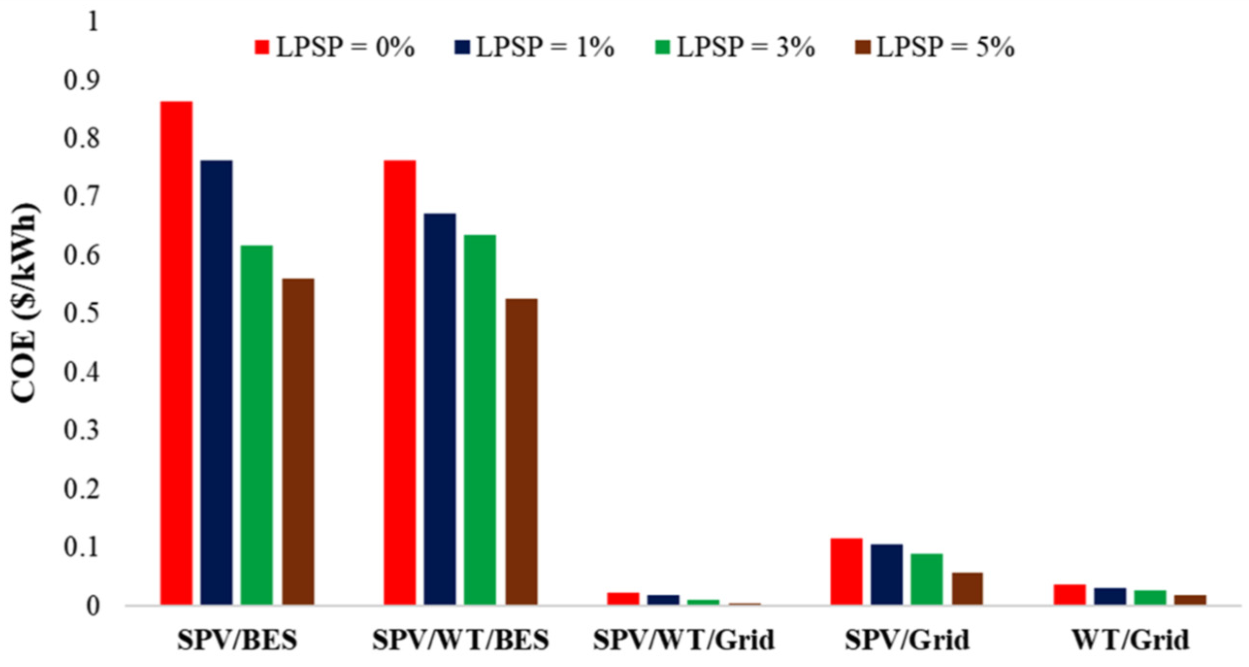
6.6. Impact of LPSP Levels on TNPC and COE for Various Configurations Using POA

This section examines the impact of varying LPSP levels on the TNPC and COE for various combinations of energy system components. It is observed that at a zero LPSP index, the SPV/WT/Grid configuration optimized by POA achieved a TNPC of USD 222,762.80. This is 24.9%, 15.1%, and 9.8% lower than the TNPC obtained for SPV/BES, SPV/WT/BES, and WT/Grid, respectively, as displayed in Figure 14. However, the SPV/Grid combination had the lowest TNPC of USD 63,615.12. Additionally, the obtained COE for SPV/WT/Grid at zero LPSP was USD 0.022/kWh, which is significantly lower, by 97.4%, 97.1%, 80.8%, and 40.5%, compared to the SPV/BES, SPV/WT/BES, SPV/Grid, and WT/Grid, respectively as shown in Figure 15. As the LPSP increased to 1% from 0%, the COE of the SPV/WT/Grid combination was reduced to USD 0.018/kWh, whereas the TNPC of the same combination was reduced by 9.3%. It is observed that as the LPSP increased, a significant reduction in TNPC and COE values took place. As the LPSP increased from 1% to 3% and 3% to 5%, the optimal COE of the SPV/WT/Grid combination decreased by 31.2% and 36.3%, respectively. Similarly, the optimal TNPC decreased by 18.7% and 11.6% as the LPSP index increased from 1% to 3% and 3% to 5%, respectively.

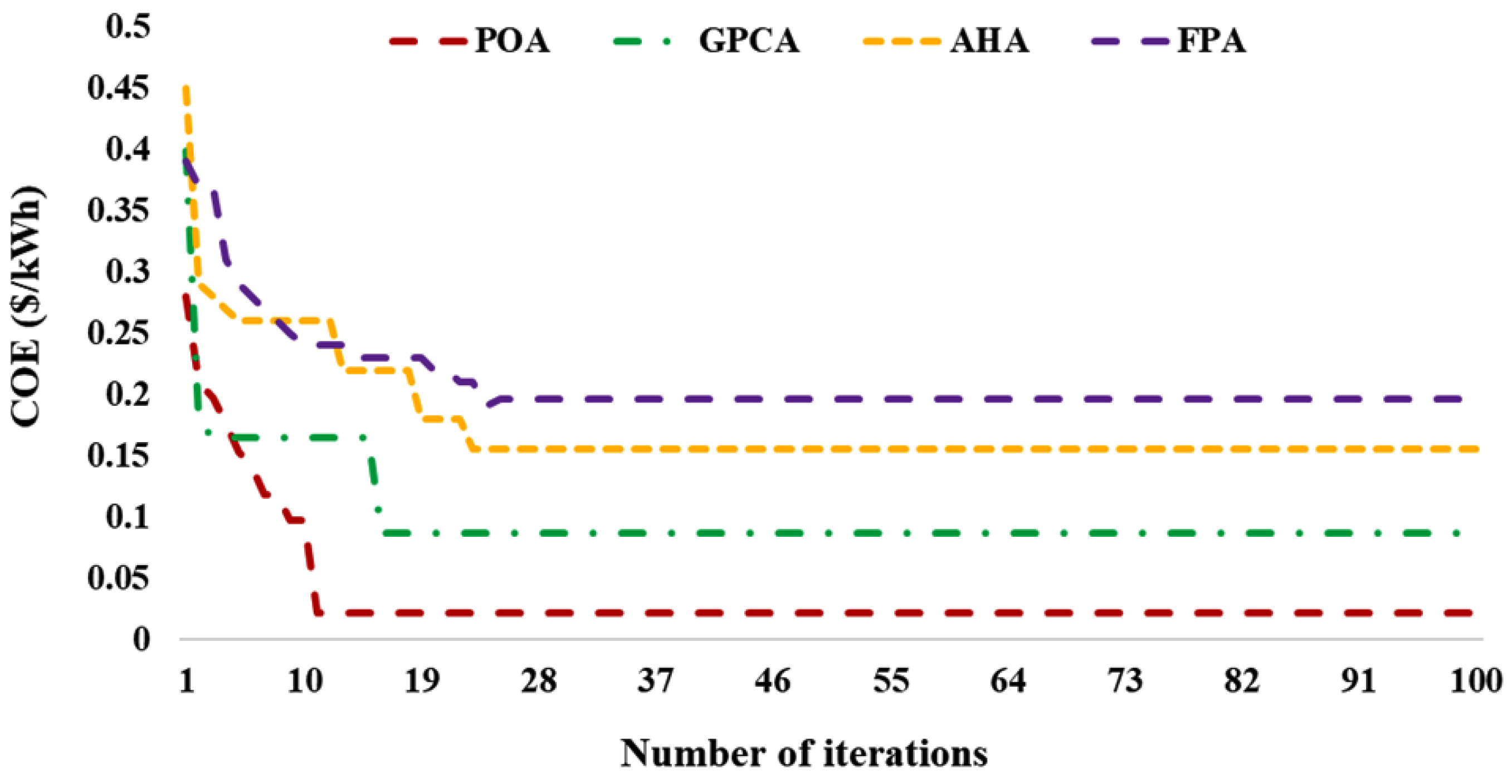
6.7. Impact of LPSP Levels on TNPC and COE for SPV/WT/Grid Combination Using Different Optimization Algorithms

The comparative analysis of the impact on the TNPC and COE for four optimization approaches, including POA, GPCA, AHA, and FPA, under varying degrees of LPSP are presented in Figure 16. The study examined the effects of LPSP indices at 0%, 1%, 3%, and 5% on the outcomes of these optimization techniques. The graph demonstrates that the optimized POA approach consistently produced the lowest TNPC and COE across all LPSP values when compared to the GPCA, AHA, and FPA methods. Notably, at a 5% LPSP index, the POA method achieved the lowest TNPC of USD 138,927.3 and the lowest COE of USD 0.007/kWh. The TNPC and COE for the best POA results ranged from USD 138,927.3 to USD 222,762.8 and from USD 0.007/kWh to USD 0.022/kWh, respectively, across the different LPSP levels. The findings also reveal that increasing the LPSP index percentage resulted in a reduction in both TNPC and COE for the optimal POA outcomes, as shown in Figure 16. Similar trends were observed for the other methods. Specifically, for the POA system, the optimal COE decreased by 27.2%, 31.2%, and 36.3% as the LPSP increased from 0 to 1%, 1 to 3%, and 3 to 5%, respectively. Similarly, the optimal TNPC determined by POA decreased by 13.1%, 18.7%, and 11.6% as the LPSP index increased from 0 to 1%, 1 to 3%, and 3 to 5%, respectively.
The optimized values of SPV panels and WT for Surat, India, with LPSP values of 0%, 1%, 3%, and 5%, are displayed in Figure 17. These values indicate the reliability of the power system, with a lower LPSP reflecting higher reliability. For Surat, when the LPSP was set to 0%, the optimal configuration included 230 SPV panels and 345 WT. This setup resulted in a TNPC of USD 222,762.80 and COE of USD 0.022 per kWh, determined using the POA. In contrast, the GPCA method required 190 SPV panels and 324 WT units to meet the PEV load demand. This configuration led to a higher TNPC of USD 354,672.20 and a COE of USD 0.054 per kWh. Additionally, other optimization methods such as the AHA and the FPA showed different configurations. AHA required 175 SPV panels and 316 WT units, while FPA needed 158 SPV panels and 298 WT units. The graph indicates a clear trend: as the LPSP value increased, the TNPC decreased. This trend can be explained as follows. When the LPSP was 1%, there was a 13% reduction in the number of SPV panels and a 10% reduction in WT units compared to an LPSP of 0%. This adjustment resulted in a 1.2% decrease in the TNPC. For an LPSP of 3%, the number of SPV panels decreased by 21.7%, and WT units by 17%. This significant reduction led to a 9% decrease in the TNPC. At an LPSP of 5%, the SPV panel count was reduced by 35%, and the WT units by 20.5%, further decreasing the TNPC by 13%. These data illustrate the trade-off between system reliability and cost: higher reliability (lower LPSP) requires more components and results in higher costs, whereas allowing for a higher LPSP reduces the number of required components and lowers the overall cost.

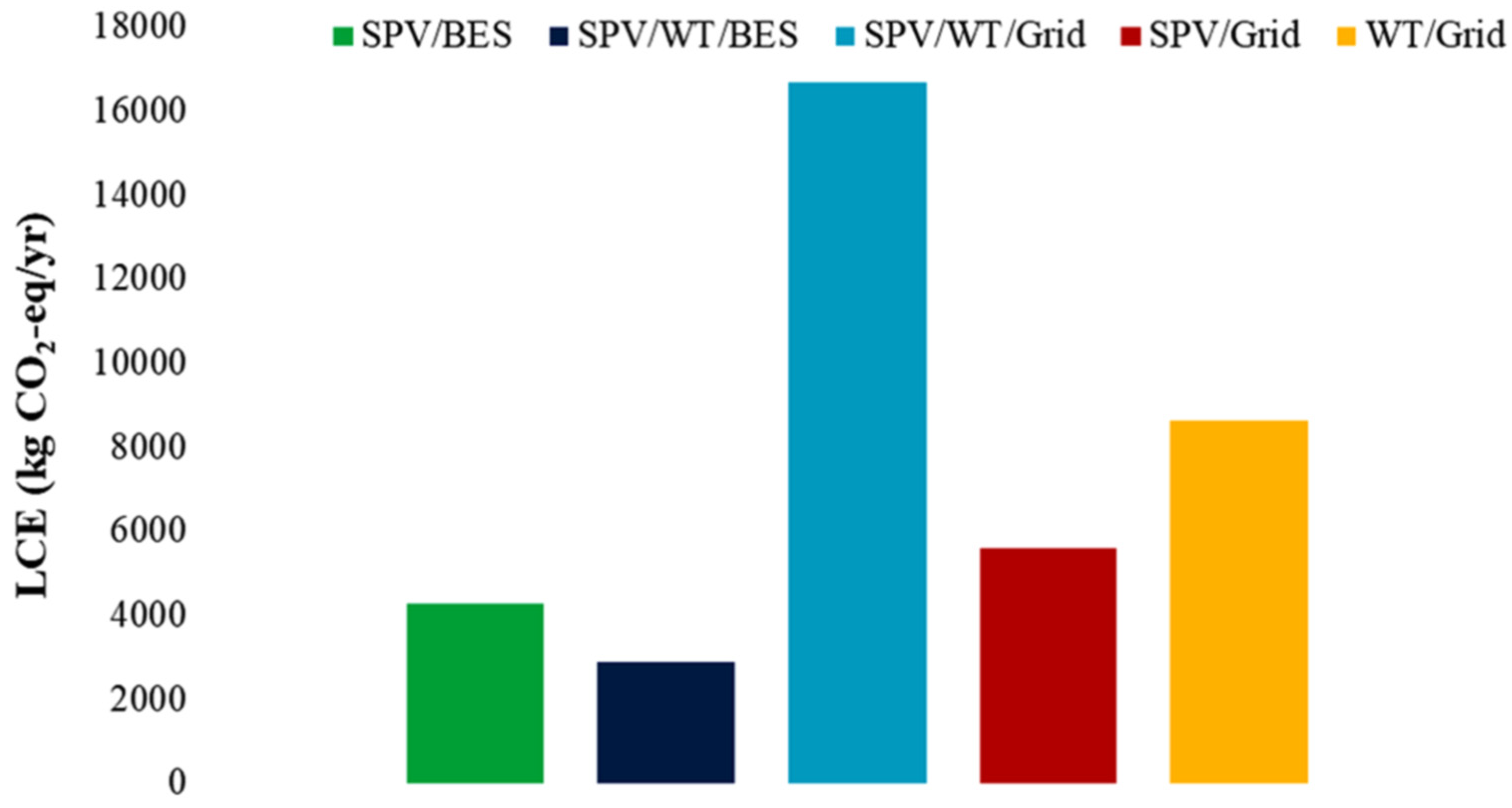
6.8. Environmental Feasibility of the Proposed PEV Charging Station Design

PEVs offer substantial environmental benefits by reducing greenhouse gas emissions, pollution, and noise. These vehicles are a critical component in the transition to more sustainable transportation. However, the source of electricity used to charge PEVs significantly impacts their overall environmental footprint. Research conducted by the American Council for an Energy-Efficient Economy highlights a crucial point: when PEVs are charged using electricity generated from coal-fired power plants, greenhouse gas emissions can actually increase, undermining the environmental advantages of PEVs.
To better understand the environmental feasibility of different PEV charging station designs, this study conducted a comprehensive life cycle emission (LCE) analysis. The analysis compared several configurations of RESs and their impact on emissions.
(1)
SPV and BES Combination:
Utilizing SPV panels paired with BES systems, this configuration resulted in an LCE of 4258.93 kg CO2-equivalent per year as shown in Figure 18. While this setup harnesses renewable solar energy, the emissions were still relatively high compared to other combinations due to the manufacturing and maintenance of the battery storage systems.
(2)
SPV, WT, and BES Combination:
Integrating both solar and wind energy with BES, this hybrid setup had the lowest LCE of 2870.31 kg CO2-equivalent per year. This configuration benefits from the complementary nature of solar and wind power, providing a more stable and lower-emission energy source.
(3)
SPV, WT, and Grid Combination:
Combining solar and wind energy with a grid connection resulted in the lowest LCE of 16,683.74 kg CO2-equivalent per year. The grid connection allows for the balancing of RESs with conventional power, optimizing the overall emissions profile.
(4)
SPV and Grid Combination:
Combining solar with a grid connection resulted in an LCE of 5601.25 kg CO2-equivalent per year. The grid connection allows for the balancing of RESs with conventional power, optimizing the overall emissions profile.
(5)
WT, and Grid Combination:
A charging station design that relies solely on the WT connected with the grid emitted a significantly higher amount of CO2, amounting to 8625.27 kg CO2-equivalent per year. This is primarily because the grid often includes a mix of renewable and non-RESs, with a substantial portion still coming from fossil fuels.
The findings of this study emphasize the importance of using RESs for charging PEVs to maximize their environmental benefits. Hybrid systems that combine multiple renewable sources and incorporate grid connectivity highlight a pathway toward a more sustainable PEV charging infrastructure.

7. Conclusions

This study thoroughly examined the scientific and economic feasibility of integrating grid and renewable energy systems for an environmentally friendly PEV charging station in Surat, India. Surat was selected due to its abundance of RESs, its pivotal role in the development of e-mobility, and its potential for rapid adoption of PEV-related policies. Our research employed the Pufferfish Optimization Algorithm (POA) to optimize the sizing of system components, aiming to reduce the TNPC and COE while ensuring reliability in terms of power supply failure probability. This method was compared to other algorithms, including the GPCA, AHA, and FPA. The study concluded that the optimal system configuration, which included solar PV, WT, and the electric power grid (SPV/WT/Grid), significantly reduced the TNPC to USD 222,762.80 and the COE to USD 0.022/kWh. This configuration, identified as C3, achieved an impressive 99.5% renewable energy penetration while effectively balancing grid energy purchases and sales. In contrast, the C1 configuration (SPV/BES), though environmentally superior with 100% renewable energy, was economically impractical due to its high TNPC and COE. Grid-integrated systems, particularly C4, demonstrated a more favorable balance of energy transactions compared to other setups, such as C5. This study also explored the effects of varying LPSP levels and diverse climatic, financial, and technological factors on system costs. Notably, the POA proved to be the most effective optimization strategy, yielding the lowest TNPC and COE values.

Author Contributions

Conceptualization, M.B., P.N.B. and G.S.; formal analysis, M.B., P.N.B. and G.S.; funding acquisition, P.N.B. and G.S.; investigation, M.B. and P.N.B.; methodology, M.B., P.N.B. and G.S.; project administration, P.N.B. and G.S.; writing—original draft, M.B.; writing—review and editing, P.N.B., G.S. and G.P. All authors have read and agreed to the published version of the manuscript.

Funding

This research received no external funding.

Data Availability Statement

The original contributions presented in the study are included in the article, further inquiries can be directed to the corresponding authors.

Conflicts of Interest

The authors declare no conflicts of interest.

Nomenclature and Abbreviations

Nomenclature
PEVPlug-in Electric VehicleBBOBranch Bound Optimizer
SDGSustainable Development GoalsGAGenetic Algorithm
SPVSolar PhotovoltaicWTWind Turbine
DGDiesel GeneratorBESBattery Energy Storage
SOCState of ChargeEMSEnergy Management Strategy
RFRenewable FractionTNPCTotal Net Present Cost
RESRenewable Energy SourcesCOECost of Energy
GWOGrey Wolf OptimizationLPSPlack of Power Supply Probability
GPCAGiza Pyramids Construction AlgorithmPOWERPrediction of Worldwide Energy Resource
FPAFlower Pollination AlgorithmACAlternating Current
MSMEMicro, Small, and Medium-sized EnterprisesDCDirect Current
PSOParticle Swarm OptimizationCRFCapital Recovery Factor
NOCTNominal Operating Cell Temperature D O D Depth of discharge
POAPufferfish Optimization AlgorithmV2GVehicle to Grid
G2VGrid to VehicleLCELife Cycle Analysis
V2VVehicle to VehicleAHAArtificial Hummingbird Algorithm
Abbreviations
E P S P V t Electrical output power of the SPV module e r Escalation rate
S I ( t ) Solar irradiance at time instant t i r Interest rate
η S P V Actual efficiency of the SPV panel n Lifespan of the project
a S P V Effective area of the SPV panel N S P V Number of SPV panels
η m a x Maximum efficiency of SPV cell C S P V r e p cost of replacement of each SPV unit
η M P P T Efficiency at the operating point of MPPT C c a p W T Capital cost of WT panel
δ t Temperature coefficient α W T Initial cost of WT
T o p t Actual operating temperature and A W T Area of WT
T r a t e d Maximum temperature of the SPV module W T Annual cost of maintaining and operating a WT system
T a m b t Ambient temperature c r e p W T Cost of replacement of each WT unit
N O C T Nominal Operating Cell Temperature N W T Number of WT
T a m b , N O C T Ambient temperature at NOCT C c a p B E S Capital cost of BES,
S I N O C T Solar irradiance at NOCT α B E S Initial cost of BES device
E P W T t Electrical power output of the wind farm P B E S Power rating of BES device
V c i Cut-in wind speed B E S Annual cost of maintaining and operating a WT system
V c o Cut-off wind speed N B E S Number of BES
P W T r a t e d Rated power of the wind turbine c r e p B E S Cost of replacement of each BES unit
V r a t e d Rated wind speed C c a p i n v Capital cost of BES
V W T Wind speed at a specific height α i n v Initial cost of the inverter
P W T G ( t ) Mechanical output power of WT P i n v Power rating of the inverter
a W T Area of the wind farm ξ s g r i d Unit cost for selling electricity to the utility grid
η W T Efficiency of the WT ξ p g r i d Unit cost of purchasing electricity from the utility grid
b and c WT constants B Number of components of energy system
E B E S t Electrical energy stored in BES at time t E L Energy generated by each system component
P B E S t Electrical power charged/discharged into/from the BES L P S P m a x Upper threshold of system reliability tolerance
ƛ Self-discharge rate of BES P p , m a x g r i d t Maximum purchase from the grid
E B E S , m i n Minimum battery energy P s , m a x g r i d ( t ) Maximum sell to the grid
D O D m a x Maximum depth-of-discharge P d e f t Deferrable load
E B E S , c a p Overall energy capacity of the battery bank N S P V m a x Maximum limit on SPV used
η i n v Efficiency of inverter N S P V m i n Minimum limit on SPV used
P i Input power to bidirectional inverter N W T m i n Minimum limit on WT used
P o u t Output power of bidirectional inverter N W T m a x Maximum limit on WT used
η 10 Efficiency at 10% of nominal power N B E S m i n Minimum limit on BES units used
η 100 Efficiency at 100% of nominal power N B E S m a x Maximum limit on BES units used
P p g r i d t Amount of energy taken from the grid T Maximum iterations
P D P E V t Energy demand of PEVs M Total number of population members
E P R E S t Electrical power output of RES Y Matrix of POA population
β b Lifetime equivalent CO2 emissions Y i i t h POA member
P s g r i d ( t ) Electrical power fed to the grid y i , d d t h dimension within the search space
C S P V c a p Capital cost of the SPV panel L B d Lower bounds of the d t h decision variable
α S P V Initial cost of the SPV system U B d Upper bounds of the d t h decision variable
A S P V Area of SPV system S P V Annual cost of maintaining and operating an SPV system

References

  1. Vayá, M.G.; Andersson, G. Self Scheduling of Plug-In Electric Vehicle Aggregator to Provide Balancing Services for Wind Power. IEEE Trans. Sustain. Energy 2015, 7, 886–899. [Google Scholar] [CrossRef]
  2. Reddy, M.S.K.; Selvajyothi, K. Optimal placement of electric vehicle charging station for unbalanced radial distribution systems. Energy Sources Part A Recovery Util. Environ. Eff. 2020, 1–15. [Google Scholar] [CrossRef]
  3. Eid, A.; Mohammed, O.; El-Kishky, H. Efficient operation of battery energy storage systems, electric-vehicle charging stations and renewable energy sources linked to distribution systems. J. Energy Storage 2022, 55, 105644. [Google Scholar] [CrossRef]
  4. Mohammad, A.; Zuhaib, M.; Ashraf, I.; Alsultan, M.; Ahmad, S.; Sarwar, A.; Abdollahian, M. Integration of Electric Vehicles and Energy Storage System in Home Energy Management System with Home to Grid Capability. Energies 2021, 14, 8557. [Google Scholar] [CrossRef]
  5. Mahmoud, F.S.; Abdelhamid, A.M.; Al Sumaiti, A.; El-Sayed, A.-H.M.; Diab, A.A.Z. Sizing and Design of a PV-Wind-Fuel Cell Storage System Integrated into a Grid Considering the Uncertainty of Load Demand Using the Marine Predators Algorithm. Mathematics 2022, 10, 3708. [Google Scholar] [CrossRef]
  6. Fares, D.; Fathi, M.; Mekhilef, S. Performance evaluation of metaheuristic techniques for optimal sizing of a stand-alone hybrid PV/wind/battery system. Appl. Energy 2022, 305, 117823. [Google Scholar] [CrossRef]
  7. Kumar, P.; Pal, N.; Sharma, H. Techno-economic analysis of solar photo-voltaic/diesel generator hybrid system using different energy storage technologies for isolated islands of India. J. Energy Storage 2021, 41, 102965. [Google Scholar] [CrossRef]
  8. Bilal, M.; Rizwan, M. Integration of electric vehicle charging stations and capacitors in distribution systems with vehicle-to-grid facility. Energy Sources Part A Recovery Util. Environ. Eff. 2021, 1–30. [Google Scholar] [CrossRef]
  9. Bilal, M.; Rizwan, M.; Alsaidan, I.; Almasoudi, F.M. AI-Based Approach for Optimal Placement of EVCS and DG With Reliability Analysis. IEEE Access 2021, 9, 154204–154224. [Google Scholar] [CrossRef]
  10. Ahmad, F.; Ashraf, I.; Iqbal, A.; Marzband, M.; Khan, I. A novel AI approach for optimal deployment of EV fast charging station and reliability analysis with solar based DGs in distribution network. Energy Rep. 2022, 8, 11646–11660. [Google Scholar] [CrossRef]
  11. Ud-Din Khan, S.; Wazeer, I.; Almutairi, Z.; Alanazi, M. Techno-economic analysis of solar photovoltaic powered electrical energy storage (EES) system. Alex. Eng. J. 2022, 61, 6739–6753. [Google Scholar] [CrossRef]
  12. Ahmad, F.; Iqbal, A.; Ashraf, I.; Marzband, M.; Khan, I. Placement of electric vehicle fast charging stations in distribution network considering power loss, land cost, and electric vehicle population. Energy Sources Part A Recovery Util. Environ. Eff. 2022, 44, 1693–1709. [Google Scholar] [CrossRef]
  13. Bilal, M.; Ahmad, F.; Rizwan, M. Techno-economic assessment of grid and renewable powered electric vehicle charging stations in India using a modified metaheuristic technique. Energy Convers. Manag. 2023, 284, 116995. [Google Scholar] [CrossRef]
  14. Li, Z.; Su, S.; Jin, X.; Xia, M.; Chen, Q.; Yamashita, K. Stochastic and distributed optimal energy management of active distribution network with integrated office buildings. CSEE J. Power Energy Syst. 2022, 10, 504–517. [Google Scholar] [CrossRef]
  15. Sadati, S.M.B.; Moshtagh, J.; Shafie-Khah, M.; Rastgou, A.; Catalão, J.P.S. Optimal Charge Scheduling of Electric Vehicles in Solar Energy Integrated Power Systems Considering the Uncertainties. In Electric Vehicles in Energy Systems; Springer International Publishing: Cham, Switzerland, 2020; pp. 73–128. [Google Scholar]
  16. Ahmad, F.; Iqbal, A.; Asharf, I.; Marzband, M.; Khan, I. Placement and Capacity of EV Charging Stations by Considering Uncertainties with Energy Management Strategies. IEEE Trans. Ind. Appl. 2023, 59, 3865–3874. [Google Scholar] [CrossRef]
  17. Marinescu, C. Progress in the Development and Implementation of Residential EV Charging Stations Based on Renewable Energy Sources. Energies 2022, 16, 179. [Google Scholar] [CrossRef]
  18. Ding, B.; Li, Z.; Li, Z.; Xue, Y.; Chang, X.; Su, J.; Jin, X.; Sun, H. A CCP-based distributed cooperative operation strategy for multi-agent energy systems integrated with wind, solar, and buildings. Appl. Energy 2024, 365, 123275. [Google Scholar] [CrossRef]
  19. Leone, C.; Longo, M.; Fernandez-Ramirez, L.M.; Garcia-Trivino, P. Multi-Objective Optimization of PV and Energy Storage Systems for Ultra-Fast Charging Stations. IEEE Access 2022, 10, 14208–14224. [Google Scholar] [CrossRef]
  20. Al-Ghussain, L.; Darwish Ahmad, A.; Abubaker, A.M.; Alrbai, M.; Ayadi, O.; Al-Dahidi, S.; Akafuah, N.K. Techno-economic assessment of photovoltaic-based charging stations for electric vehicles in developing countries. Energy Sources Part A Recovery Util. Environ. Eff. 2023, 45, 523–541. [Google Scholar] [CrossRef]
  21. Zhang, H.; Zhai, X.; Zhang, J.; Bai, X.; Li, Z. Mechanism Analysis of the Effect of the Equivalent Proportional Coefficient of Inertia Control for a Doubly Fed Wind Generator on Frequency Stability in Extreme Environments. Sustainability 2024, 16, 4965. [Google Scholar] [CrossRef]
  22. Syed Mohammed, A.; Anuj; Lodhi, A.S.; Murtaza, Q. Techno-economic feasibility of hydrogen based electric vehicle charging station: A case study. Int. J. Energy Res. 2022, 46, 14145–14160. [Google Scholar] [CrossRef]
  23. Borroy Vicente, S.; Fernández, G.; Galan, N.; Llombart Estopiñán, A.; Salani, M.; Derboni, M.; Giuffrida, V.; Hernández-Callejo, L. Assessment of the Technical Impacts of Electric Vehicle Penetration in Distribution Networks: A Focus on System Management Strategies Integrating Sustainable Local Energy Communities. Sustainability 2024, 16, 6464. [Google Scholar] [CrossRef]
  24. Nishanthy, J.; Charles Raja, S.; Praveen, T.; Jeslin Drusila Nesamalar, J.; Venkatesh, P. Techno-economic analysis of a hybrid solar wind electric vehicle charging station in highway roads. Int. J. Energy Res. 2022, 46, 7883–7903. [Google Scholar] [CrossRef]
  25. Nandini, K.K.; Jayalakshmi, N.S.; Jadoun, V.K. Risk-based dynamic pricing by metaheuristic optimization approach for electric vehicle charging infrastructure powered by grid integrated microgrid system. Electr. Power Syst. Res. 2024, 230, 110250. [Google Scholar] [CrossRef]
  26. Oladigbolu, J.O.; Mujeeb, A.; Al-Turki, Y.A.; Rushdi, A.M. A Novel Doubly-Green Stand-Alone Electric Vehicle Charging Station in Saudi Arabia: An Overview and a Comprehensive Feasibility Study. IEEE Access 2023, 11, 37283–37312. [Google Scholar] [CrossRef]
  27. Verma, R.; Sharma, S.K.; Singh, P.; Bhutto, J.K.; Alharbi, A.R.A. Analysis and Sizing of Charging Stations in Kota City. Sustainability 2022, 14, 11759. [Google Scholar] [CrossRef]
  28. Karmaker, A.K.; Hossain, M.A.; Pota, H.R.; Onen, A.; Jung, J. Energy Management System for Hybrid Renewable Energy-Based Electric Vehicle Charging Station. IEEE Access 2023, 11, 27793–27805. [Google Scholar] [CrossRef]
  29. Krishnamurthy, N.K.; Sabhahit, J.N.; Jadoun, V.K.; Gaonkar, D.N.; Shrivastava, A.; Rao, V.S.; Kudva, G. Optimal Placement and Sizing of Electric Vehicle Charging Infrastructure in a Grid-Tied DC Microgrid Using Modified TLBO Method. Energies 2023, 16, 1781. [Google Scholar] [CrossRef]
  30. Vellingiri, M.T.; Mehedi, I.M.; Palaniswamy, T. A Novel Deep Learning-Based State-of-Charge Estimation for Renewable Energy Management System in Hybrid Electric Vehicles. Mathematics 2022, 10, 260. [Google Scholar] [CrossRef]
  31. Ahmadi, S.E.; Kazemi-Razi, S.M.; Marzband, M.; Ikpehai, A.; Abusorrah, A. Multi-objective stochastic techno-economic-environmental optimization of distribution networks with G2V and V2G systems. Electr. Power Syst. Res. 2023, 218, 109195. [Google Scholar] [CrossRef]
  32. Ekren, O.; Hakan Canbaz, C.; Güvel, Ç.B. Sizing of a solar-wind hybrid electric vehicle charging station by using HOMER software. J. Clean. Prod. 2021, 279, 123615. [Google Scholar] [CrossRef]
  33. Alsaidan, I.; Bilal, M.; Alaraj, M.; Rizwan, M.; Almasoudi, F.M. A Novel EA-Based Techno–Economic Analysis of Charging System for Electric Vehicles: A Case Study of Qassim Region, Saudi Arabia. Mathematics 2023, 11, 2052. [Google Scholar] [CrossRef]
  34. Oladigbolu, J.O.; Mujeeb, A.; Imam, A.A.; Rushdi, A.M. Design, Technical and Economic Optimization of Renewable Energy-Based Electric Vehicle Charging Stations in Africa: The Case of Nigeria. Energies 2022, 16, 397. [Google Scholar] [CrossRef]
  35. Nguyen, H.T.; Choi, D.-H. Distributionally Robust Model Predictive Control for Smart Electric Vehicle Charging Station With V2G/V2V Capability. IEEE Trans. Smart Grid 2023, 14, 4621–4633. [Google Scholar] [CrossRef]
  36. Yang, D.; Sarma, N.J.S.; Hyland, M.F.; Jayakrishnan, R. Dynamic modeling and real-time management of a system of EV fast-charging stations. Transp. Res. Part C Emerg. Technol. 2021, 128, 103186. [Google Scholar] [CrossRef]
  37. Khan, W.; Ahmad, F.; Alam, M.S. Fast EV charging station integration with grid ensuring optimal and quality power exchange. Eng. Sci. Technol. Int. J. 2019, 22, 143–152. [Google Scholar] [CrossRef]
  38. Almutairi, A. Impact Assessment of Diverse EV Charging Infrastructures on Overall Service Reliability. Sustainability 2022, 14, 13295. [Google Scholar] [CrossRef]
  39. Wang, B.; Dehghanian, P.; Zhao, D. Coordinated Planning of Electric Vehicle Charging Infrastructure and Renewables in Power Grids. IEEE Open Access J. Power Energy 2023, 10, 233–244. [Google Scholar] [CrossRef]
  40. Ullah, Z.; Wang, S.; Wu, G.; Hasanien, H.M.; Rehman, A.U.; Turky, R.A.; Elkadeem, M.R. Optimal scheduling and techno-economic analysis of electric vehicles by implementing solar-based grid-tied charging station. Energy 2023, 267, 126560. [Google Scholar] [CrossRef]
  41. Omar, N.; Kumar Tiwari, A.; Seethalekshmi, K.; Anand Shrivastava, N. A Novel Controller Design for Small-Scale Islanded Microgrid Integrated with Electric Vehicle-Based Energy Storage Management. Int. Trans. Electr. Energy Syst. 2022, 2022, 5059215. [Google Scholar] [CrossRef]
  42. Al Wahedi, A.; Bicer, Y. Assessment of a stand-alone hybrid solar and wind energy-based electric vehicle charging station with battery, hydrogen, and ammonia energy storages. Energy Storage 2019, 1, e84. [Google Scholar] [CrossRef]
  43. Engelhardt, J.; Zepter, J.M.; Gabderakhmanova, T.; Marinelli, M. Energy management of a multi-battery system for renewable-based high power EV charging. eTransportation 2022, 14, 100198. [Google Scholar] [CrossRef]
  44. Al Wahedi, A.; Bicer, Y. Development of an off-grid electrical vehicle charging station hybridized with renewables including battery cooling system and multiple energy storage units. Energy Rep. 2020, 6, 2006–2021. [Google Scholar] [CrossRef]
  45. Bilal, M.; Alsaidan, I.; Alaraj, M.; Almasoudi, F.M.; Rizwan, M. Techno-Economic and Environmental Analysis of Grid-Connected Electric Vehicle Charging Station Using AI-Based Algorithm. Mathematics 2022, 10, 924. [Google Scholar] [CrossRef]
  46. Kamal, M.M.; Ashraf, I.; Fernandez, E. Sustainable electrification planning of rural microgrid using renewable resources and its environmental impact assessment. Environ. Sci. Pollut. Res. 2022, 29, 86376–86399. [Google Scholar] [CrossRef]
  47. Kamal, M.M.; Mohammad, A.; Ashraf, I.; Fernandez, E. Rural electrification using renewable energy resources and its environmental impact assessment. Environ. Sci. Pollut. Res. 2022, 29, 86562–86579. [Google Scholar] [CrossRef] [PubMed]
  48. Anand, P.; Rizwan, M.; Bath, S.K. Sizing of renewable energy based hybrid system for rural electrification using grey wolf optimisation approach. IET Energy Syst. Integr. 2019, 1, 158–172. [Google Scholar] [CrossRef]
  49. Jahangiri, M.; Nematollahi, O.; Haghani, A.; Raiesi, H.A.; Alidadi Shamsabadi, A. An optimization of energy cost of clean hybrid solar-wind power plants in Iran. Int. J. Green Energy 2019, 16, 1422–1435. [Google Scholar] [CrossRef]
  50. Mandal, S.; Das, B.K.; Hoque, N. Optimum sizing of a stand-alone hybrid energy system for rural electrification in Bangladesh. J. Clean. Prod. 2018, 200, 12–27. [Google Scholar] [CrossRef]
  51. Nirbheram, J.S.; Mahesh, A.; Bhimaraju, A. Techno-economic optimization of standalone photovoltaic-wind turbine-battery energy storage system hybrid energy system considering the degradation of the components. Renew. Energy 2024, 222, 119918. [Google Scholar] [CrossRef]
Figure 1. Schematic layout of the proposed HES.
Energies 17 04194 g001
Figure 2. Studied location.
Energies 17 04194 g002
Figure 3. Hourly load profile of PEVs.
Energies 17 04194 g003
Figure 4. Solar irradiance and wind speed data of the studied location.
Energies 17 04194 g004
Figure 5. Energy management strategy for the SPV/WT/grid-based designing of PEV load.
Energies 17 04194 g005
Figure 6. Implementation of POA for optimizing the system objectives.
Energies 17 04194 g006
Figure 7. Convergence behavior of the different algorithms.
Energies 17 04194 g007
Figure 8. Comparison of economic indicators for various combinations of hybrid renewable energy systems.
Energies 17 04194 g008
Figure 9. Comparison of economic indicators for optimal configuration using various optimization approaches.
Energies 17 04194 g009
Figure 10. Power assessment for SPV/WT/grid configuration for the PEV charging station during the (a) winter (b), spring (c), summer, and (d) autumn seasons.
Energies 17 04194 g010
Figure 11. Power supplied by different energy sources in meeting PEV load demand in the Surat region.
Energies 17 04194 g011
Figure 12. NPC breakdown of different components of the optimal configuration.
Energies 17 04194 g012
Figure 13. Energy purchased and sold from/to the grid in different months of the year.
Energies 17 04194 g013
Figure 14. Varying behavior of TNPC of the system for different LPSP levels.
Energies 17 04194 g014
Figure 15. Varying behavior of the COE of the system for different LPSP levels.
Energies 17 04194 g015
Figure 16. Impact of LPSP levels on the system’s objectives optimized using different optimization algorithms.
Energies 17 04194 g016
Figure 17. Optimal quantity of SPV and WT units at various LPSP levels.
Energies 17 04194 g017
Figure 18. Life cycle emission analysis for different possible configurations.
Energies 17 04194 g018
Table 2. Basic cost details for various system components.
ComponentSPVWTBESInverter
ManufacturerGeneric flat plateGenericGeneric lead acidGeneric
Capital cost (USD)13001098235127
Replacement cost (USD)01098190127
Operation and Maintenance cost (USD)20221
Rated capacity (kW)1101 kWh1
Lifetime (years)25201515
Lifetime equivalent CO2 emissions (kg CO2-eq per year)0.0450.0110.028
Table 3. Comparison of attained outcomes using pufferfish algorithm for various designs of PEV load.
Configurations for PEV CS ModelSPV/BESSPV/WT/BESSPV/WT/GridSPV/GridWT/Grid
PEV charging station scenariosC1C2C3C4C5
COE (USD/kWh)0.86420.76320.0220.11500.03
TNPC (USD)296,975.10262,254.80222,762.80283,615.1247,177.40
Number of SPV used57387515
Number of WT used1224225
Battery units276342
Converter capacity (kW)38.76019.719.7
Renewable fraction (%)10010099.550.298.8
SPV production (kWh/year)94,64363,32712,619124,002
Wind production (kWh/year)1872645,722636,062
Grid purchase (kWh/year)390221,8347849
Grid sales (kWh/year)741,49416,606615,212
Disclaimer/Publisher’s Note: The statements, opinions and data contained in all publications are solely those of the individual author(s) and contributor(s) and not of MDPI and/or the editor(s). MDPI and/or the editor(s) disclaim responsibility for any injury to people or property resulting from any ideas, methods, instructions or products referred to in the content.

