Review

Contemporary and Conventional Passive Methods of Intensifying Convective Heat Transfer—A Review

by
Ewa Kozłowska
and
Marek Szkodo
*
Institute of Manufacturing and Materials Technology, Faculty of Mechanical Engineering and Ship Technology, Gdańsk University of Technology, 11/12 Gabriela Narutowicza Street, 80-233 Gdańsk, Poland
*
Author to whom correspondence should be addressed.
Energies 2024, 17(17), 4268; https://doi.org/10.3390/en17174268
Submission received: 30 June 2024 / Revised: 22 August 2024 / Accepted: 22 August 2024 / Published: 26 August 2024
(This article belongs to the Section J1: Heat and Mass Transfer)

Abstract

:
The ever-increasing demand for effective heat dissipation and temperature control in industrial and everyday applications highlights a critical research problem. The need for development is not only in terms of providing thermal comfort to humans but also forms the basis for the efficient operation of machines and equipment. Cooling of industrial machinery and household electronic equipment is a crucial element in any manufacturing process, and the planning and design of appropriate cooling systems continues to be an integral part of the machine design and construction process. Manufacturers aim to maximize performance while minimizing size and weight. This article reviews widely used passive methods to enhance heat transfer, focusing on their effectiveness in improving convective heat transfer. The techniques examined include surface modifications and advanced materials like foamed metals and nanostructured coatings, which influence turbulence and heat transfer coefficients. The key findings demonstrate that surface roughness, perforated fins, and twisted tapes enhance fluid mixing but may increase flow resistance. The review underscores the significance of these passive methods in optimizing cooling system efficiency across various applications. Despite the variety of techniques available, many areas, especially those involving laser beam modifications, remain underexplored, indicating a need for further research in this field.

1. Introduction

Subjects related to the temperature control of selected areas added to the constantly increasing demand for improved methods of both heat dissipation and the cooling of equipment applied in industry and everyday life are the focus of this research. The need for development prevails in the context of providing thermal comfort to humans, but it also forms the basis for the efficient operation of machinery and equipment. The cooling of industrial machinery and domestic electronic devices is an extremely important element of any manufacturing process, and the planning and design of appropriate cooling systems remains an integral part of the process of machinery design and construction. Manufacturers of such equipment are constantly aiming to maximize performance while minimizing product dimensions and weight.
This review examines the fundamentals of heat exchange, leading to the development of heat exchanger techniques, and also presents and analyzes various techniques, including surface modifications and advanced materials like foamed metals and nanostructured coatings, along with their roles in enhancing turbulence and heat transfer coefficients. Additionally, this paper demonstrates promising enhancements in thermal performance achieved by using innovative surface modification techniques. Moreover, it points out some challenges remaining in translating laboratory findings to real-world applications.
Heat is thermal energy (kinetic and potential energy of microparticles) moving from one body to another in the direction of temperature drop according to the Second Law of Thermodynamics [1]. Heat transfer always takes place from a body with a higher temperature to a body with a lower temperature until a state of thermal equilibrium is reached and is one of the ways of transferring energy between thermodynamic systems. The second is work. There are three ways of heat transfer—conduction, radiation, and convection [1,2].
Heat conduction is the transfer of energy through the vibration of molecules in solids and stationary liquids and gases. The heat always flows in the direction of the temperature drop. The heat conduction capacity of a substance is determined by its thermal conductivity coefficient, λ [2]. Determining the thermal conductivity of various materials, especially metals, was the subject of many studies as early as the turn of the eighteenth and nineteenth centuries. Knowledge of the thermal conductivity of a given material is one of the basic pieces of information taken into account in many fields when selecting construction materials. At the same time, it is a value that cannot be measured directly, so over the decades, along with the development of other branches of technology, research methods have also developed to learn about the thermodynamic properties of individual materials. For interesting facts about historical and contemporary methods for determining the thermal conductivity of materials, see this comprehensive review article by Simon Reif-Acherman [3]. The conclusions of the review underscore the tremendous progress made over the years. However, the scientist’s observations also include discrepancies in science between data through modeling and those obtained experimentally. Materials with extreme coefficient values, λ, are often used in specific conditions. An example is diamond, which for centuries served only as a precious jewelry stone, but after the discovery of some of its mechanical properties—high hardness and good thermal conductivity—it is now used in a completely different way—as a component of machining tools or as an element to prevent supercapacitors from overheating during assembly [3]. Many new materials remain unexplored or insufficiently studied for thermal conductivity, providing a prospect for future generations of scientists to continue their work in this area.
Thermal radiation is the transfer of energy with the help of electromagnetic waves emitted as a result of the thermal movement of molecules. These waves are characterized by a range of wavelengths invisible to the human eye (mainly infrared waves). Heat transfer by radiation can occur through a vacuum, the best example of which is the transport of thermal energy transferred from the Sun to the Earth [1,2].
Convective heat transfer, which occurs in liquids and gases, occurs as a result of the macroscopic movement of substance molecules and their contact with each other and with the limiting surface. There are two types of convection—free, which consists of automatic motion resulting from the difference in density of the medium transferring heat, and forced convection, which is the movement of the medium resulting from the supply of energy from the outside [1,2].
Heat transfer is the transfer of heat energy from one medium at a given temperature to the interior of the partition and from the partition to another medium. Convection is the main content of heat transfer, but at the partition wall, where the convective movement disappears, heat conduction through a given layer takes place. The heat transfer in a given medium is influenced, among other things, by the temperature difference—the greater the temperature difference, the more heat will be transferred. The mechanism of heat transfer through the flat partition is schematically presented in Figure 1.
The heat transfer energy flux transmitted through the area of 1 m2 of a partition made of a given material, when the temperature difference in the media separated by the partition is 1 K, is indicated by the value of the heat transfer coefficient k. The heat transfer coefficient k depends on many factors, among which the following can be mentioned: temperature, specific heat of the fluid, density of the fluid washing the partition, thermal conductivity of the fluid, heat flux density, partition material, and shape and surface type of the partition [1,2,4].
The second extremely important coefficient characterizing the heat transfer between the wall and the surrounding fluid or gas is the heat transfer coefficient α. This coefficient is a function of many variables, depending on the flow parameters, such as the velocity and nature of the flow (laminar, transient, or turbulent), as well as, in the case of a liquid stream, the thermophysical properties of the fluid itself outside [1,5].
The intensification of heat transfer is most often carried out by such a selection of flow conditions so as to achieve a developed turbulent flow, which mostly means to achieve the value of the Reynolds number Re ≥ 10,000. In fluid mechanics, the Reynolds number (Re) is a dimensionless quantity that helps predict fluid flow patterns in different situations by measuring the ratio between inertial and viscous forces. At low Reynolds numbers, flows are dominated by the laminar flow, whereas, at high Reynolds numbers, flows are usually turbulent. Turbulence results from differences in the velocity and direction of the fluid, which can sometimes intersect or even move in the opposite direction of the general flow, creating eddy currents that agitate the flow. By reaching a value of Re ≥ 10,000, a rapid increase in the value of the heat transfer coefficient α is obtained. However, this is not always possible, which is why alternative methods of increasing the transfer of heat energy between the fluid and the partition are constantly being sought [1,5,6,7].
The intensification of convective heat transfer has been the subject of interest of scientists since the 1950s. Scientists often began their investigations with observations of nature. An interesting, though mysterious, figure associated with the exploration of thermodynamic phenomena was Wiktor Schauberger. Schauberger was a forester who was particularly interested in the self-sustaining vortex motion of the flow of liquids observed in forest streams, accompanied by a decrease in water temperature. The result of his investigations were structures that improved the flow of beams and a conical and finned pipe accelerating the movement of water, which at the same time caused strong turbulence, reduced temperature, and increased flow density. There are many legends surrounding the figure of the forester–scientist, but sources indicate that his designs were the basis for many patents and a source of inspiration for scientists many years after his death [8].

2. The Variety of Heat Transfer Intensification Methods

One of the most frequently cited publications in the literature is Bergles’ review work, in which he presents a basic classification of methods of heat transfer intensification [9,10]. According to the classification presented by Bergles, there are three basic types of method of heat transfer intensification—passive, active, and combined methods. Passive methods do not require the direct input of additional energy from outside the system. Passive methods include, among other things, surface modification, surface development, surface roughening, curvature of the channel, flow turbulence, and the introduction of additives to the working liquid. Active methods require the supply of additional energy, such as the vibration of a surface or fluid, the use of an electrostatic field, the extraction or injection of fluid, and the formation of streams (including microjets). Combined methods are a combination of two or more passive methods or the simultaneous use of passive and active methods [7,9,10].
The foundations of the theory of heat transfer were proposed by Antoine Lavoisier (1743–1794) in 1789 based on the caloric theory, which states that caloric heat is a liquid substance that is massless, colorless, odorless, and tasteless. When heat is added to a body, the temperature of that body will increase, and when heat is removed from a body, the temperature of that body will decrease [11,12]. In 1843, the Englishman James P. Joule conducted a careful experiment that proved that heat is not a substance. As a result, the caloric theory was rejected. In later years, Lavoisier’s theory was combined with the law of conservation of energy. The caloric theory continues to show the valuable physical aspects of heat. Heat is a form of energy that can be transferred from one system to another as a result of a temperature difference. Most mechanical and electrical systems generate heat during operation, which leads to overheating, which is one of the most common causes of failure [11,13].
A heat exchanger is a device that is used to transfer heat between two environments, for example, from a hot fluid to a cold fluid, or vice versa. Heat exchange can take place by direct contact (diaphragm heat exchangers) or through a partition (recuperator). These devices are commonly used in all engineering applications such as heating, refrigeration, air conditioning, and power plants. Heat exchangers can be divided into different types depending on their design and application [11,14,15]. The basic classification of heat exchangers distinguishes the following systems, shown schematically in Figure 2.
  • Co-current—the flow of media takes place in parallel and consistent directions;
  • Counter-current (counterflow)—the flow of media takes place in parallel and opposite directions;
  • Cross—the flow of factors takes place in directions perpendicular to one another;
  • Mixed—the design of the exchanger combines the features of two or more systems.
Another type of classification of heat exchangers includes a division in terms of design and distinguishes three basic groups [1,15]:
  • Diaphragmless heat exchangers—heat exchange occurs during direct contact of factors and is inseparably related to mass exchange;
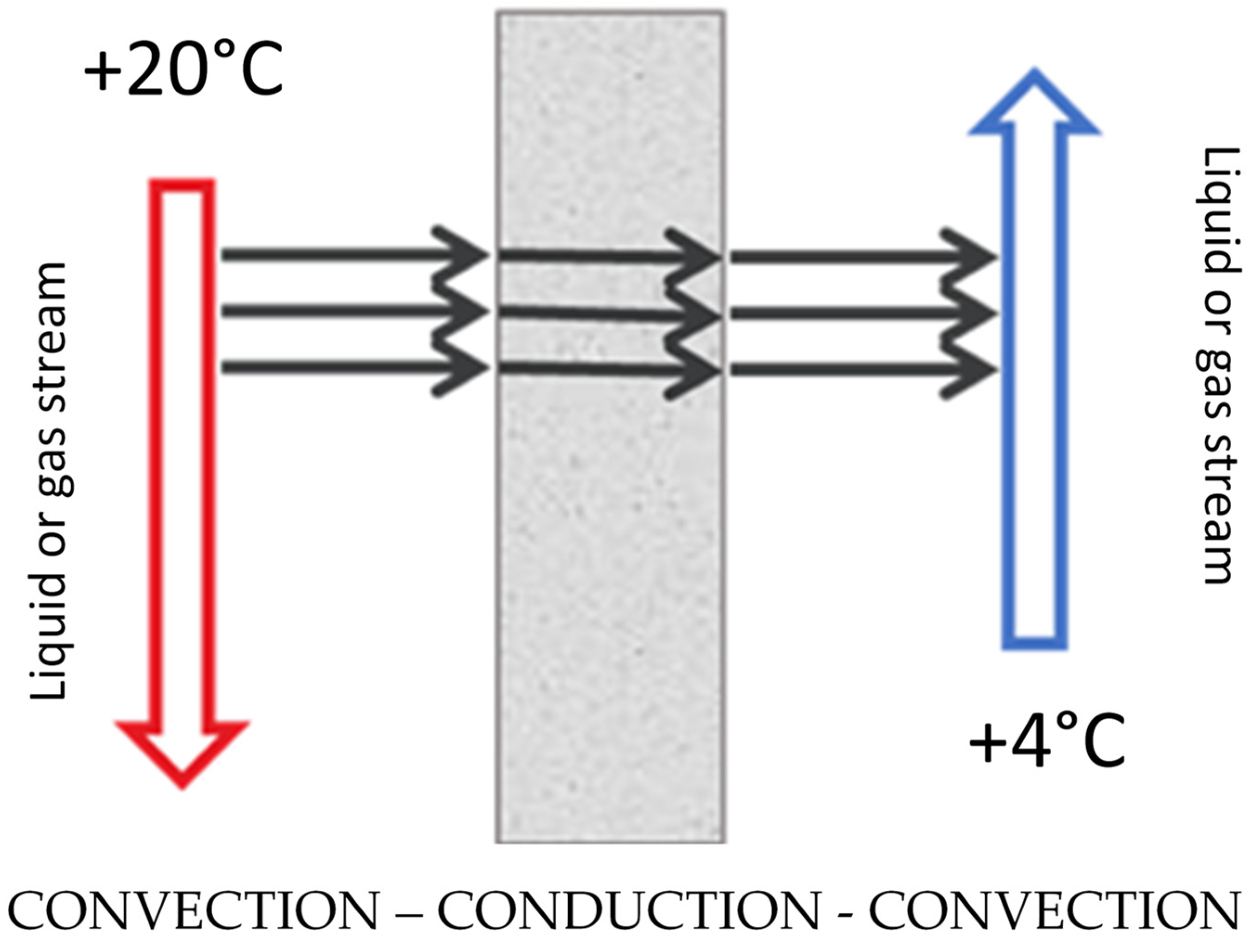
  • Recuperators—heat exchange agents are separated from one another by a partition through which heat penetrates (usually the partition is made up of pipe walls, sometimes plates); heat from the medium with a higher temperature is taken over by the wall, then heat conduction through the partition takes place, and in the next step heat is transferred from the other side of the partition by a medium with a lower temperature;
  • Regenerators—heat transfer takes place through a solid material filling, which can move or remain stationary; fluids flow in them alternately through channels in the filling mass.
A comprehensive review of techniques to improve single-phase heat transfer dedicated to potential applications in heat exchangers can be found in the review article by Alam Tabish and Kim Man-Hoe [16]. The article contains short but exhaustive descriptions of many currently used methods of intensifying heat transfer in heat exchangers.
Each type of heat exchanger employs distinct design principles that can be enhanced through various methods of heat transfer intensification. For example, diaphragmless exchangers benefit from direct fluid contact and turbulence, recuperators leverage material properties and surface modifications, and regenerators optimize flow patterns and surface interactions. Understanding these relationships is vital for improving the efficiency of thermal systems across multiple applications [16,17,18].

3. New Approaches to Heat Exchangers’ Construction

Recent advancements in the construction and optimization of heat exchangers aim to enhance their performance, efficiency, and sustainability. From structural parameter optimization and advanced numerical studies to the application of new materials and design concepts, these new approaches promise to enhance the performance and efficiency of heat exchangers across various industries.
Hussein et al. conducted a comprehensive review on the impact of structural parameters and designs on the performance of various heat exchangers. By examining different configurations and materials, they highlighted how changes in these parameters could significantly affect heat transfer efficiency, pressure drop, and overall thermal performance. The key findings included the importance of optimizing fin geometries and tube arrangements to maximize thermal conductivity and minimize energy losses [19].
Marzouk et al. provided another comprehensive review of various methods to enhance heat transfer in shell-and-tube heat exchangers. Techniques such as surface modifications, the use of nanofluids, and the insertion of turbulators were discussed. The review demonstrated how these methods could significantly boost heat transfer rates and improve overall performance [17].
In a similar vein, Marzouk et al. performed a comparative numerical study investigating the performance of shell-and-tube heat exchangers with different baffle configurations. They found that the type and arrangement of baffles could drastically influence the fluid flow patterns, thus affecting heat transfer rates and pressure drops. Their study provided valuable insights into the design of baffle structures to improve heat exchanger efficiency [20,21].
Rao and Majethia focused on the optimization of shell-and-tube heat exchangers using advanced algorithms, particularly Rao algorithms and their variants. Their research demonstrated that these optimization techniques could significantly improve the design process by identifying the best configurations that enhance heat transfer while minimizing cost and material usage. The application of such algorithms represents a significant step forward in the rational design of efficient heat exchangers [22].
Rashidi et al. provided an extensive review on the exergy analysis of shell-and-tube heat exchangers. Exergy analysis is a powerful tool to assess the efficiency and sustainability of thermal systems. Their findings emphasized the role of exergy destruction minimization in optimizing heat exchanger performance. The study underscores the importance of considering both energy and exergy analyses in the design and optimization process to achieve greater sustainability [23].
Indumathy et al. reviewed the modeling and control of plate heat exchangers, with a specific focus on continuous high-temperature, short-time (HTST) milk pasteurization processes. They discussed various control strategies and their effectiveness in maintaining desired temperature profiles while ensuring energy efficiency. Their review highlighted the potential of advanced control systems in optimizing the operation of plate heat exchangers in the food industry [24].
Joybari et al. explored the potentials and challenges of pillow-plate heat exchangers, an emerging technology in heat exchanger design. Pillow-plate heat exchangers, known for their compact and flexible structure, offer significant advantages in terms of heat transfer efficiency and mechanical strength. The review shed light on the current state-of-the-art and identified areas requiring further research to overcome existing challenges [25].
In another study, Khail and Erişen investigated the heat transfer and performance enhancement of a novel plate heat exchanger design. Their research presented experimental results highlighting the significant performance improvements achieved through innovative design modifications. This study underscores the potential of novel plate heat exchanger designs in achieving higher efficiency and compactness [26].
Finally, Marzouk et al. evaluated the effects of bifurcation angles on the performance of a novel heat exchanger based on contractual theory. Their results revealed that the appropriate selection of bifurcation angles could lead to substantial improvements in heat transfer performance. This novel approach provides a new direction for the design of efficient heat exchangers [27].

Helically Coiled Tubes

Helically coiled tubes are widely used in heat exchangers due to their enhanced thermal performance and compact design. The unique geometry of these tubes increases the turbulence of fluid flow, which significantly enhances heat transfer.
In 2022, Xu et al. conducted a comprehensive numerical study on heat transfer enhancement in helically coiled specifically-shaped tube heat exchangers. Using computational fluid dynamics (CFD), they analyzed the effects of geometrical parameters on thermal performance. Their findings indicated that variations in coil pitch and tube diameter significantly influence the heat transfer coefficient and pressure drop, thereby optimizing thermal efficiency in nuclear engineering applications [28].
Miansari et al. investigated the thermal performance of helically grooved shell and coil tube heat exchangers. Their numerical approach focused on the impact of grooves on fluid flow and heat transfer. The study demonstrated that grooves could effectively enhance thermal performance by increasing the surface area and turbulence of the fluid, leading to more efficient heat transfer [29].
Tuncer et al. investigated the thermal performance enhancements of a novel shell and helically coiled heat exchanger design. The authors focused on evaluating the heat transfer efficiency and pressure drop characteristics of the improved design. They utilized experimental data and numerical simulations to assess the performance, showing that the new design exhibited significantly better thermal performance while maintaining manageable pressure drops, compared to traditional configurations. The study highlights the potential applications of this heat exchanger in various industrial processes requiring efficient thermal management [30].
Wang et al. employed a multi-objective optimization method called MO-SHERPA to investigate the optimal shape design and performance of helically coiled tube heat exchangers. This method allowed for the assessment of multiple parameters simultaneously, optimizing both heat transfer and fluid dynamics characteristics. The results highlighted the fact that the optimized shapes significantly improved both thermal efficiency and reduction in pressure losses [31].
There is also a great number of experimental or combined studies.
Ali et al. conducted an experimental validation and numerical investigation to optimize heat transfer in double coil heat exchangers. Their study focused on the impact of different coil configurations and flow rates. The experimental results showed a considerable agreement with the numerical findings, affirming the potential for optimizing these parameters to enhance heat transfer performance [32].
Fan et al. explored the flow and heat transfer characteristics in the eccentric annulus of the helically coiled tube-in-tube heat exchangers used in aero-engine applications. By combining experimental data with numerical simulations, the study provided insights into the complex interactions within the coils. Their findings suggested that optimizations in annular space geometry could lead to significant performance improvements in aeronautical heat exchangers [33].
Lebbihiat et al. examined the thermal performance of helical ground–air heat exchangers under hot climate conditions through both in situ measurements and numerical simulation. Their research highlighted the importance of situational design adjustments to improve the efficiency of heat exchangers in varying environmental conditions [34].
Liu et al. investigated the thermal-hydraulic performance of a tube-in-tube helical coil air–fuel heat exchanger for use in an aero-engine. The authors conducted experiments to evaluate the heat transfer efficiency and pressure drop characteristics of the heat exchanger. The results indicated improved thermal performance and optimized pressure drops, suggesting that the tube-in-tube helical coil design is suitable for enhancing the efficiency of aero-engine heat exchangers [31,35].
Pathak, Shukla, and Sagade presented a comprehensive heat transfer analysis of a small-scale Organic Rankine Cycle (ORC) system incorporating a novel multi-helical coil heat exchanger. The study examined the performance of the system under various operating conditions and provided detailed thermal analysis data. The findings showed that the multi-helical coil design enhances the heat transfer efficiency, making the system viable for power generation applications [36].
Another piece of research by Marzouk et al. explored the thermal performance and fluid dynamics of a novel fractal tube configuration within a helically coiled heat exchanger. Both experimental and numerical methods were employed to analyze heat transfer rates and pressure drops. The fractal tube design demonstrated enhanced heat transfer coefficients compared to traditional helical coils, suggesting a potential for applications requiring efficient thermal management [37].
Vivekanandan et al. examined the impact of a flower baffle on the performance of a helical coil heat exchanger through both experimental and computational fluid dynamics (CFD) methods. The study assessed heat transfer rates and fluid flow patterns, noting significant improvements in thermal performance due to the introduction of the flower baffle. The research supports the use of baffles for enhanced heat exchanger efficiency in industrial settings [38].
Scientists working on the topic of helically coiled tubes also placed an emphasis on advanced optimization techniques.
Heydari et al. used Taguchi’s empirical method to optimize the hydrothermal performance of helically corrugated coiled tube heat exchangers. This method involved energy and exergy analysis to find the optimal configuration that maximized heat transfer while minimizing exergy destruction. The study concluded that certain corrugation patterns significantly enhanced the thermal performance of the heat exchangers [39].
Han et al. investigated heat transfer exergy loss numbers to optimize shell and helically coiled tube heat exchangers. Their approach focused on minimizing exergy loss to maximize thermal efficiency. The results indicated that specific coil designs could reduce thermal irreversibility, thereby improving overall system performance [40].

4. Passive Methods

Passive methods include changing the surface roughness, developing the surface by using multiple technics (including machining, laser melting, and many more), swirling the flow with twisted tapes, and introducing elements that generate vortices [7,9,10,16].

4.1. Ribs, Perforations, Partitions

Passive methods include changing the surface roughness, developing the surface, swirling the flow with twisted belts, and introducing elements that generate vortices [16].
One of the most common methods of intensifying heat transfer in the literature is the reconstruction of the heat exchanger structure by adding fins or partitions, which were often perforated [11,18,41,42,43].
A. Sadeghianjahromi and C.-C. Wang prepared a comprehensive review that examined various mechanisms employed to enhance heat transfer in fin-and-tube heat exchangers. The authors reviewed numerous studies focusing on different geometric modifications, surface treatments, and innovative structural designs aimed at boosting thermal performance. The review highlights the effectiveness of each mechanism and provides a comparative analysis, shedding light on the most promising approaches for optimizing heat exchanger efficiency. The findings offer valuable guidelines for designing more efficient heat exchange systems in various industrial applications [18].
In their research, Mikuz and Tiselj dealt with the changes in flow turbulence caused by the addition of a spacer grid. On the tested section, elements called “flow rectifiers” were used, whose task was to stabilize the flow and eliminate vortices at the inlet into the test area before the stream of liquid flowed through the tested mesh [42]. These studies confirmed an increase in flow turbulence through the grid. The developed numerical model was compared with existing ones and its effectiveness was confirmed. However, the publication does not contain specific data on changes in the values of heat transfer or heat transfer coefficients.
Perforating the ribs is aimed at reducing their weight. Properly made holes can also contribute to increasing the intensity of heat transfer, as it increases the heat transfer surface and affects the turbulence of the fluid flow in the fin area [11,41]. Awasarmol and Pise, in their 2015 paper [41], showed that the heat transfer coefficient will always be greater for perforated fins compared to non-perforated fins. The magnitude of the changes depends on the size of the holes and the angle of inclination of the fins relative to the liquid stream. The tests were carried out for aluminum fins with dimensions of 75 × 25 × 75 mm. Five holes were made on the surface of each rib, with diameters of 6, 8, 10, and 12 mm, respectively. The angle of inclination for each series was 0°, 30°, 45°, 60°, and 90°, respectively. The results were analyzed in the context of increasing the heat transfer coefficient and reducing the weight of the components. The best results were achieved with holes with a diameter of 12 mm, with the exchanger fins set at an angle of 45°. The heat transfer coefficient was increased by 32%, while the heat exchanger weight was reduced by 30% [41].
Experimental work by Ibrahim et al. from 2018 focused on the shapes of the rib perforations [11]. Previously, it was shown that the heat transfer rate and heat transfer coefficient increased with increasing perforation diameter. Perforation shapes are also becoming an important aspect in achieving the maximum heat transfer coefficient. The paper presents the course of an experiment performed for three types of perforation of exchanger fins.
The research showed that the perforation of the ribs resulted in a higher temperature difference compared to the non-perforated ribs, which affected the distribution of heat supplied along the ribs. The drilling of the holes resulted in an increase in the value of the heat transfer coefficient in the range from 35.82% to 51.29%. It has also been shown that different hole shapes contribute to the increase of the heat transfer coefficient to a different extent.
Another type of study was conducted by Kurian, Balaji, and Venkateshan. They investigated the impact of installing a stainless-steel mesh in the heat exchanger structure on its efficiency. In a 2016 article [43], the efficiency of three heat exchangers in a liquid-gas cross-flow system was experimentally compared. The first one was made of copper pipes embedded in a system of stainless-steel wire meshes, and the second one was made of copper pipes embedded in aluminum foam with a porosity of 0.94. The third heat exchanger—the reference one (without additional modifications)—was made of copper tubes with identical dimensions as the previous ones. The heat exchangers were tested under forced convection conditions in a vertical open-loop wind tunnel. The external working medium in this system was air, while distilled water was responsible for the transfer of heat inside the pipes. The authors of the study emphasize the simplicity and economical nature of the heat exchanger. Studies have shown that a stainless-steel mesh exchanger shows better performance than a foamed aluminum exchanger. Compared to an unmodified heat exchanger, there is a maximum efficiency increase of 2.25 times. By comparing the heat transfer coefficients on the water side, it was observed that the intensity of heat transfer increases with the velocity of the air inlet and the temperature of the water inlet. In the Reynolds number range studied, the heat exchanger gives a 40–45% improvement in heat transfer parameters compared to a foam heat exchanger [43].
In 2020, Pham et al. published their new study that investigated the impact of boot-shaped ribs on the heat transfer characteristics within the internal cooling passages of turbine blades. The research utilized both experimental and numerical methods to evaluate how these specially designed ribs influence thermal performance. The results demonstrated a significant enhancement in heat transfer due to the rib geometry, leading to improved cooling efficiency within the turbine blades. The findings provide valuable insights into optimizing rib design for advanced thermal management in gas turbines [44].
Dinh, Do, Chung, et al. explored the effects of pin-fins with trapezoidal endwalls on heat transfer within the internal cooling channels of gas turbine blades. Through both numerical and experimental approaches, the study revealed that incorporating trapezoidal endwalls significantly enhances heat transfer performance when compared to traditional cylindrical pin-fins. The enhancements are attributed to the increased surface area and improved flow distribution, leading to more effective cooling in turbine applications [45].
Another group of scientists, including Dinh, Nguyen, et al., focused on a numerical investigation on how truncated-root ribs affect the heat transfer performance within the internal cooling channels of turbine blades. The study employs computational fluid dynamics (CFD) to simulate various configurations of truncated-root ribs, analyzing their impact on thermal efficiency and fluid flow characteristics. The results indicate that these ribs offer notable improvements in heat transfer rates, making them a promising design for enhancing the cooling efficiency of turbine engines [44,46].

4.2. Metal Foams

Foamed metal, also known as metal foam, is a metallic material that contains a large number of pores filled with gas. In the literature, a distinction is made between foams with open pores and those with closed pores. Closed-pore foams exhibit greater rigidity because they have membranes in their structure that separate adjacent cells or voids, while open-pore foams have a network structure of randomly spaced, but interconnected, voids [47]. Effective techniques for producing expanded metals are not yet widely known, and they are still the subject of research or patents. Anirban Changdar and Shitanshu Shekhar Chakraborty, in their review work, emphasize the great potential of additive techniques [47,48]. The advantages of metal foams include the following: low density while maintaining similar mechanical properties to metals, the ability to retain heat, dampened shocks and sounds, and the ability to absorb crush energy. Expanded metals can be used as a structural material in a wide range of industries, including transportation; electrical engineering, for example, batteries, fuel cells, and supercapacitors; and chemical apparatus manufacturing [48].
Expanded metals, mainly aluminum or copper foams, are of great interest to researchers involved in cooling electronic devices, including computer processors and microprocessors. The metal foam used in the fan structure, thanks to its porous structure, ensures better airflow between the components, which consequently increases the efficiency of convective, forced heat exchange [48,49]. Concepts using copper or aluminum foams in the construction of fans are still the subject of experimental research and numerical studies [48,49]. In the work of Paknezhad et al., it was shown that the use of aluminum foam as a heat sink increases the cooling efficiency of the element by up to 17%. However, this solution has drawbacks, which include an increase in sound intensity during fan operation, an increase in energy consumption, and an increase in the weight and volume of the device [47].

4.3. Twisted Tapes

Initially, research concerned the increase in the intensity of heat transfer inside smooth pipes [50,51]. In 1978, Marner and Bergles [52] experimentally showed that, for a pipe with axial internal finning and a twisted strip insert, the heat transfer amplification with laminar oil flow in the pipe can be three times higher for heating and four times for cooling. The heat transfer parameters of the aqueous ethylene glycol solution, in which the mass fraction of ethylene glycol is between forty and sixty percent when using turbulent flow in pipes with internally grooved surfaces and continuous twisted strip inserts, were determined by the team of Usui et al. [53]. Studies have shown that, for the same pump power, the heat transfer coefficients inside pipes with this type of composite reinforcement were 3 to 3.5 times higher than inside a hollow smooth pipe [51].
Suri and his team conducted experimental studies of perforated twisted tapes. The square holes, the exact dimensions of which are not given in the publication, were made on twisted strips inside a tube with an internal diameter of 65 mm. Studies have shown that perforations increased the thermal efficiency of the belts in the range of 6.96% to 8.34% [54]. Similar studies were conducted by Mashoofi et al., who tested twisted strips with longitudinal holes with a maximum size of 5 mm. Numerical tests in this case showed the possibility of a maximum increase in heat transfer efficiency at the level of 9.9%, depending on the turbulence of the flow [55].
Based on the author’s research [51], Polish scientists Zawadzki et al. concluded that the method of combined heat transfer enhancement with twisted strips is suitable for improving heat transfer conditions at the laminar flow of a high-viscosity fluid, while it has a small effect on transient and turbulent flow, where a slight improvement in the heat transfer coefficient was observed with a significant increase in flow resistance [51].
Extensive studies comparing the effectiveness of modifications in the form of triangular fins on the inner tube of a two-tube exchanger and twisted strips on the outer surface of the exchanger were conducted by Hameed and Hussein [56]. It was shown that the total heat transfer coefficient inside the pipe increased with the increase in the amount of hot water in each case. It was observed that the heat transfer efficiency is highest for the fin tube with a twisted strip, followed by for the finned tube only, and the lowest for the smooth tube. The increase in the heat transfer coefficient is related to the fact that the fins, which are used to expand the inner surface of the pipe, help to distribute heat towards the cold area, and the twisted strip partially cuts off the water supply to certain areas, as a result of which a thick boundary layer cannot be formed. However, the boundary layer was formed when the stream is in contact with the pipe, which flowed at a slower speed than that in the core. The overall efficiency of internal and external heat-flow amplification for this experiment can be summarized as 2.6 for the finned tube only and 3.5, 4.8, and 5.2 for a strip-finned tube with a twist ratio of 7, 5, and 3, respectively [56].
Recently, Liaw, Kurnia, and Sasmito started to explore the impact of twisted tape inserts on laminar convective heat transfer within helical tubes. The authors conducted a comprehensive analysis using both experimental data and computational models to accurately understand the flow and heat transfer characteristics. The twist ratio and pitch of the tape are critical parameters evaluated to determine their effect on heat transfer enhancement. The results indicated that twisted tape inserts considerably improve heat transfer rates in laminar flow by promoting swirl flow and improving fluid mixing, leading to higher thermal performance. Optimal configurations of these inserts were also identified to balance the heat transfer benefits and pressure drop [57].
The same group of scientists investigated the enhancement of turbulent convective heat transfer in helical tubes using twisted tape inserts. The researchers employed both experimental and numerical approaches to assess the performance of twisted tape inserts under turbulent flow conditions. Their findings showed a significant increase in heat transfer rates attributable to the intensified turbulence and secondary flow induced by the twisted tapes in the helical tubes. Furthermore, the study identified the optimal geometric configurations of the twisted tapes, which maximize the heat transfer efficiency while mitigating the pressure drop penalties typically associated with turbulence enhancers [58].
Both studies highlight the significant role twisted tape inserts play in augmenting convective heat transfer in helical tubes, albeit under different flow regimes—turbulent and laminar. They provide valuable insights into the optimal design of these inserts, balancing the trade-offs between enhanced heat transfer and pressure drops.

4.4. Surface Layers Modifications

The surface layer of a given object is the surface of the material, i.e., the outer layer of the material that limits the actual surface of the object, as well as the subsurface area—the zones covering this surface and the part of the material deep into the real surface, which show changed physical and chemical characteristics in relation to the characteristics of the core material. In Poland, this is defined by the PN-87/M-04250 standard [59]. In the surface layer, the following zones can be conventionally distinguished:
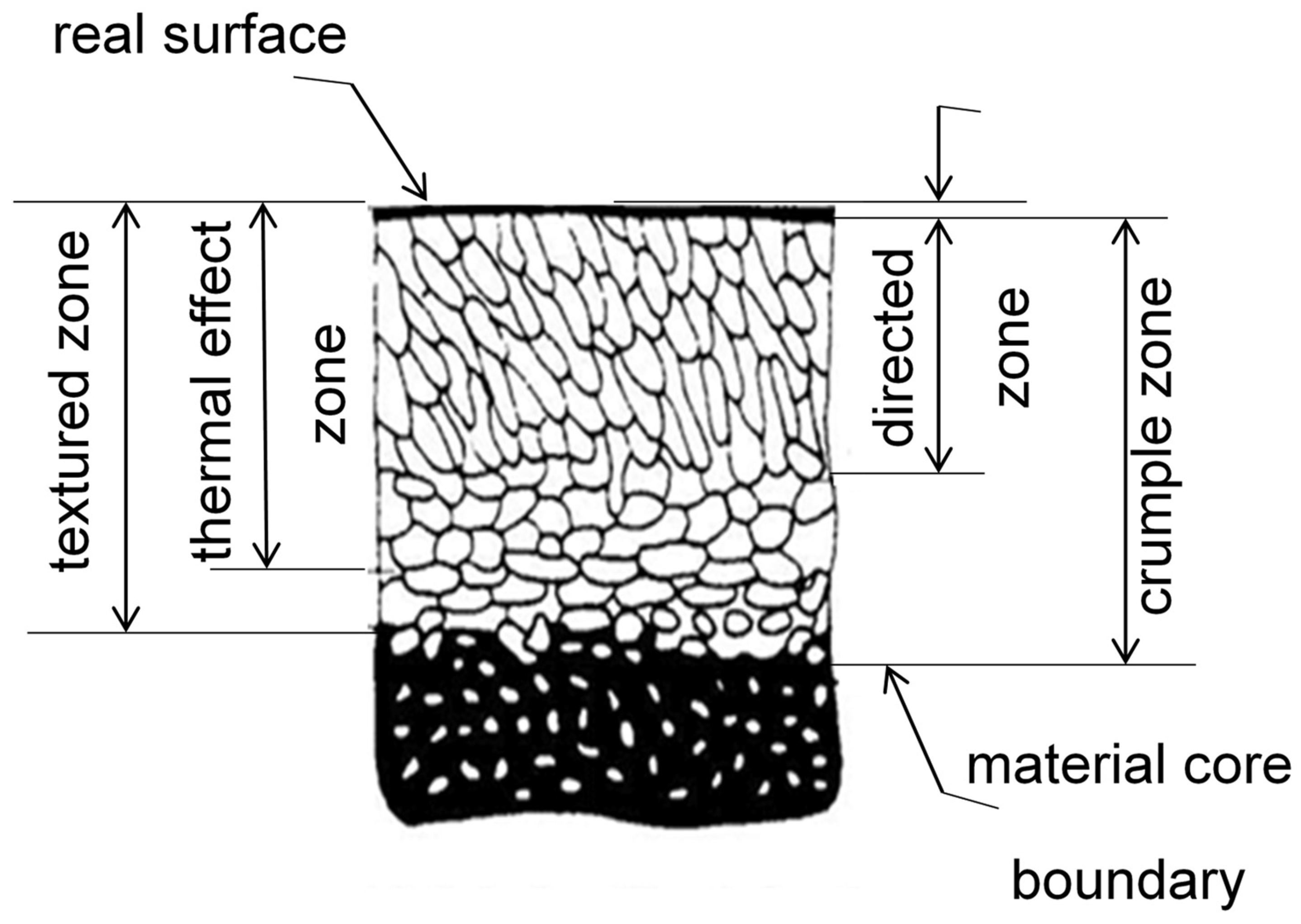
  • Near-surface zone—directly adjacent to the real surface, does not have a proper structure;
  • Directed zone—there are directed grains in it,
  • Thermal effect zone—there is a change in grain size, phase transitions, or chemical reactions caused by thermal processes;
  • Textured zone—there is a crystalline texture in it;
  • Crumple zone—the zone in which plastic deformation has occurred.
  • The conventional division of zones in the surface layer is presented in Figure 3.
Due to the fact that the issue of intensification of heat transfer by modifying the surface layers of materials is an extremely complex area of science, the assessment of the effectiveness of individual modifications has become more and more complicated with the development of technology. Researchers have attempted to simplify the evaluation by creating a list of criteria that define the performance of the equipment and the benefits of using a given surface layer modification in the heat exchanger under study compared to an exchanger with unmodified surfaces [60,61,62,63,64].
Webb’s 1980 work [61] describes the elaborations developed by the teams of Bergles et al. [63,64] and Webb et al. [65,66], called Performance Evaluation Criteria (PEC). The PEC criteria apply to single-phase flow in tubes and only consider the thermal performance and material content of the heat transfer surface used in the heat exchanger. The PEC criteria do not include additional material structures and flow losses. Instead, they take into account the reinforcement and ripple effects on the shell side, making them applicable to rough and internally finned tubes. The introduction of the criteria created a method for reviewing different improvement techniques in order to identify those that offer the most potential. PEC is a fundamental component that can be incorporated into more complex optimization programs that develop methods to minimize the total cost of production of a heat exchanger or maximize system efficiency.
The detailed procedures for calculating the efficiency improvement and optimization of the surface geometry using the PEC criteria described in the paper are presented for four design cases: reduced heat exchanger area; increased heat load; reduced logarithmic mean temperature difference; and reduced pumping power. The eleven cases discussed in the paper cover both a fixed and a variable flow area. Suitable PECs for two-phase heat exchangers are also discussed [61,62].
In order to define the improvement of heat exchanger efficiency, three basic design objectives have been formulated [61]:
  • Reduction in the volume or weight of the heat transfer surface material for the same pumping power and heat load, which can result in lower production costs.
  • Increasing the total heat transfer coefficient for equal pumping power and constant total length of the exchanger tubes, which can be achieved in two ways:
  • by obtaining an increased heat load for a constant temperature of the influent liquid;
  • by providing a reduced mean logarithmic temperature difference for a constant heat load.
  • Reduction of pumping power for equal heat load and total length of exchanger tubes.
The PEC criteria can be divided into three groups due to the use of three types of geometric constraints:
FG—Fixed geometry criteria, which consist of replacing smooth pipes with modified pipes of the same length. They can be considered as “retrofit” applications. The FG-1 criterion is designed to increase the heat load or heat transfer coefficient for a constant flow rate and velocity. The pumping power of the exchanger with a developed surface will increase due to the increased friction characteristic of the developed surface. The FG-2 criterion has the same purpose as the FG-1, but it requires that the developed tube structure operates with the same pumping power as the reference smooth tube design. The pumping power is kept constant by reducing the velocity on the tube side and thus the flow rate in the exchanger. Since the FG-2 assumes a lower flow rate on the pipe side, the average logarithmic temperature difference will be reduced, resulting in a lower heat transfer efficiency than the FG-1. The third criterion (FG-3) is designed to reduce the pumping power at constant heat load.
FN—Fixed flow criterion, which is used to maintain a constant flow area. For a shell-and-tube heat exchanger with a fixed pipe diameter, this means that the number of tubes and the shell diameter are constant. The purpose of the FN-1 is to reduce the surface area, by reducing the length of the pipes, for a constant pumping power. To meet the criterion of constant pumping power, the flow rate may need to be reduced. Modified pipes are used in the FN-2 to achieve reduced pumping power at a constant flow rate.
VG—Variable Geometry Application variable geometry case, which describes a case different from most, where the heat exchanger is dimensionally adjusted as standard for the required heat load at a given flow rate (then the FG and FN criteria do not apply). By using variable geometry, the flow area is increased to maintain a constant flow rate. The speed on the tube side must be reduced to accommodate the higher surface friction characteristics. This is achieved by using more parallel pipes or by using the same number of pipes but with a larger diameter. Maintaining a constant flow rate in the exchanger avoids the risk of failure resulting from operating at higher thermal efficiency in the previous FG and FN cases. However, the dimensions of the exchanger must be increased, which will increase the cost of production. Criteria VG-1, VG-2, and VG-3 correspond analogously to criteria FN-1, FN-2, and FG-3, with an important difference being the reduction of the flow rate in the case of criteria from the FN group [61].
The Performance Evaluation Criteria (PEC) developed by Bergles and elaborated upon by Webb in 1980 [61] are essential for assessing the thermal performance of heat exchangers, particularly in single-phase flow conditions. The PEC criteria serve as a valuable tool in the design, evaluation, and optimization of heat exchangers. By focusing on thermal performance and material content, these criteria help engineers make informed decisions that enhance efficiency, reliability, and overall performance in various applications. Many industries adopt PEC as part of their design and evaluation standards, ensuring consistency and reliability in heat exchanger performance assessments. The PEC criteria are used for design optimization by evaluating aspects like thermal performance assessment, where they help engineers evaluate the thermal efficiency of different heat exchanger designs. By comparing the performance of various configurations, designers can select the most effective design for specific applications. Moreover, PEC criteria consider the material properties of the heat transfer surfaces, guiding the selection of materials that enhance thermal conductivity and corrosion resistance.
What is more, PEC provides a standardized framework for comparing the performance of different heat exchangers under similar operating conditions. This facilitates benchmarking against established performance metrics. Applying PEC helps to identify specific areas where heat transfer efficiency can be improved, such as optimizing surface area or enhancing fluid flow characteristics.
The performance evaluation criteria can also be used to evaluate existing heat exchangers and suggest modifications or retrofits that enhance performance without requiring complete redesigns. Furthermore, PEC provides a framework to ensure compliance with multiple regional and international industrial regulations.
As for experimental validation, the PEC criteria are often used in conjunction with experimental setups to validate the thermal performance of new designs. By comparing measured performance against PEC benchmarks, researchers can confirm the effectiveness of their designs. Furthermore, engineers use computational fluid dynamics (CFD) and other simulation tools alongside PEC to predict performance and guide the design process [60,61,62,64].
Over the years, many different methods have been developed to modify the surface layer of materials to intensify heat transfer. Surface layer modifications can be broadly divided into coating, where surface features are altered by directly coating the base surface; internal modifications, where altered surface features are an intrinsic part of the material surface; and hybrid modifications, which are a combination of the previous two methods [67].
Techniques for creating coated surfaces include epoxy bonding, nanoparticle dipping, spray coating, sintering, electrochemical deposition, and chemical vapor deposition. The increase in the heat transfer coefficient of coated surfaces ranges from 32% to more than 17 times compared to reference surfaces. Surface coating techniques have resulted in a significant increase in heat transfer efficiency, making them an attractive solution for many refrigeration applications. However, as coatings are not an integral part of the substrate surface, the thermal resistance between the coating and the substrate and the coating’s tendency to degrade and peel over time are a weakness of this solution. Before starting to implement individual methods for practical applications, a number of individual durability and durability tests of a given modification should be carried out [67,68].
Modifications that alter the internal characteristics of the surface include machining, electrical discharge machining (EDM), mechanical surface roughening, micro/nano-electro-mechanical processes (MEMS/NEMS), open-cell foams, and modifications created with the help of a laser beam [67].
One of the basic methods of surface development found in the literature is the formation of convexities aimed at developing the flow by creating vortices around the protuberance. Different shapes of protrusions in the canal can cause the formation of whirlpools, usually horseshoe-shaped. The intensity of vortex formation and changes in flow turbulence depends on many factors, such as the shape of the protrusions, their size, and their distribution. Intensification of heat transfer by creating vortices in the laminar flow is usually preferred over turbulent flow generation. An ordered laminar flow with local vortices forming in the direction of flow is associated with a smaller increase in entropy of the system than the corresponding chaotic turbulent flow [69].
Canpolat [70], along with Sahin [71], studied the effect of producing a single groove along a cylindrical convexity depending on the position of the groove relative to the flow direction. It has been shown that the size of the groove and its angular position have a significant effect on the structure of the near excitation, the turbulence statistic, and the frequency of vortex generation. Experimental results on the boundary layer made it possible to determine the critical angular position of the groove, θ = 80 ° . Flow separation is delayed in the range of 0 ° θ 80 ° , while early separation of the boundary layer occurs from θ = 80 ° . In addition, asymmetry in the flow structure was observed. Therefore, it was concluded that a longitudinal single rectangular groove on a cylinder-shaped convexity could be used to reduce flow–structure interaction and control flow [70,71].
Forooghi, Flory, et al. numerically studied the flow and heat transfer in a single tube of a flat tube heat exchanger with passive inserts. The arrangement of the protrusions was not symmetrical, leaving an area without inserts on one side of the canal. The results suggest that the resulting local turbulence contributes to increased heat transfer at high Reynolds numbers; however, the asymmetrical arrangement of the inserts was unfavorable, especially in the case of laminar-turbulent transient flow [72].
Based on the premise that improving boiling heat transfer through surface modification is critical to improving the efficiency of many energy systems, but at the same time improving all boiling heat transfer characteristics, including critical heat flux, heat transfer coefficient, and seed boiling onset, usually has conflicting requirements for surface wettability and morphology [73]. They proposed a novel method to improve all boiling heat transfer properties by increasing the density of bubble nucleation sites, rewetting the liquid induced by capillaries, and separating the liquid-vapor pathways. This method is based on surrounding long nanowire arrays with short nanowires, and microcavities are formed between short clusters of nanowires. On surfaces developed in this way, a 71% greater critical heat flux, a 185% higher heat transfer coefficient, and a 37% lower seed boiling start were observed compared to the heat transfer efficiency of a typical copper surface. In addition, an analytical model was used to predict the influence of surface structure on the heat transfer efficiency of boiling. The presented solution shows the potential application of water distillation in the energy industry, but any possible implementation would have to be preceded by more research [73].
Hu, Xu, Zhao, et al. conducted experimental studies to investigate the effect of a nanoporous surface on heat transfer during cooling in a pool of liquid nitrogen. The results showed that the nanoporous surface improved heat transfer [74].
It was estimated that a nanoporous anodized aluminum oxide (AAO) surface could save 20% of cryogen consumption in cryogenic quenching applications by reducing the cooling time compared to an unmodified surface [74].
Using the Thermal Chemical Vapor Deposition (TCVD) process, Taha, Mojet, et al. [75] produced carbon nanofiber (CNF) layers and modified the surface of a 50 μm nickel wire. In order to investigate the effect of morphology on the heat transfer characteristics, three different morphologies of CNF layers were made at 500 °C, 600 °C, and 700 °C. Experimental results showed that the CNF layer causes additional thermal resistance at 500 °C, which is due to the dense structure of the fiber layer. The heat transfer efficiency of the modified wire was 26% to 53% lower in this case. In the experiment, it was not possible to obtain an intensification of heat transfer from samples produced at 500 °C in any measurement range. However, samples made at 600 °C showed a relatively porous CNF layer and slightly lower thermal conductivity than samples made at 500 °C. This is due to the fact that the porous structure increases the flow permeability, thus reducing the thermal resistance of the layer. The change in heat transfer intensification on this sample ranges from 24% to −22% using the largest inner and outer diameters, respectively. This result shows how important it is to determine the effective diameter to obtain the accurate dimensionless heat transfer properties of samples. Samples taken at 700 °C were coated with an amorphous carbon layer and a dense CNF layer. The combined effect of a highly conductive layer, high effective heat transfer surface, and rough surface morphology contributed to a 34% increase in heat transfer for the corresponding diameter range. However, the researchers point out that it is difficult to effectively determine the diameter of samples to quantify their dimensionless heat transfer behavior [75].
Experimental research at the nanoscale was also conducted by Li, Liu, and Zheng [76]. It was assumed that the topography and chemical properties of the surface layer could be altered and controlled by surface modification. The experiment used two types of modified heat transfer surfaces: chemically treated smooth nickel-based surfaces and nano-conical matrix nickel-based hydrophilic surfaces. The quantitative influence of surface characteristics on the boiling heat transfer parameters of a saturated basin using water at atmospheric pressure was investigated and summarized. The effect of surface characteristic parameters, including nano-scale roughness (Ra), liquid–solid contact angle (CA), and effective heat transfer surface coefficient on modified smooth surfaces and nanocone surfaces, was also investigated. A number of relationships were shown in the discussion of the results of the research, but it was not clearly indicated which of the modified surfaces showed better results [76].
The thermodynamic effects of surface functionalization by the deposition of metal oxide nanostructures were studied by Das, Saha, and Bhaumik. The research concerned the nanostructures of silicon oxides, SiO2 [77], and the crystalline nanostructures of titanium oxides, TiO2 [78]. Electron beam vapor deposition was used to prepare SiO2 and TiO2 layers on a copper substrate of different thicknesses. The coated surfaces were studied using X-ray diffraction, a scanning field emission electron microscope, and an atomic force microscope, which revealed the formation of crystalline nanostructures. The modified surfaces were also used for germ boiling studies, during which an increase in the heat transfer coefficient was observed [77,78]. A maximum of an eighty percent increase in the boiling heat transfer coefficient in the germ basin was achieved by the SiO2 coating, by the formation of cavities and by improving the hydrophilicity of the modified surface, increasing the bubble formation areas and faster bubble release frequency from the nanostructured SiO2 surfaces. A relationship was observed that a higher surface-to-volume ratio of nanostructures increases the effective heating surface [77]. The effect of TiO2 nanocoating thickness on heat transfer was also investigated, and it was shown that the boiling heat transfer coefficient increases significantly with increasing TiO2 coating thickness. It was also found that the nanostructured surfaces in repeated tests of the heat transfer process remained stable, with almost the same heat transfer coefficient [78].

4.4.1. Microchannels

An impressive number of studies have been devoted to improving the thermal performance of microchannels. Their small size and ability to dissipate heat makes them one of the best solutions for improving the cooling of electronic circuits. Initially, the studies conducted between 1982 and 2002 were largely done using experimental methods, and the discrepancies between analytical and experimental results were large, while more recent studies (since 2003) have used numerical methods. The values of the heat transfer parameters obtained, thanks to these methods, were much more accurate [79].
A current extensive piece of research on recent trends in microchannels for heat transfer and thermal management applications was published in 2022 by Harris et al. [80]. The key research themes covered in the review were materials, experimental, design, and sustainability (MEDS), and their sub-themes were determined and were categorized as follows: Materials (working fluids, nanofluids/nanoparticles, and surface treatment/manipulation); Experimental (flow boiling, phase change, flow resistance, thermal resistance, and manufacturing techniques); Design (aspect ratios, geometry/shape manipulation, barriers, and pin-fins); Sustainability perspective (no general theme, environmental, economic, and social). The study found that the heat transfer performance of enhanced microchannel systems can be improved by incorporating asymmetrical barriers, pin-fins, unconventional geometries, mixed-wettability/biphilic surfaces, and hybrid/silver nanofluids, and by utilizing innovative experimental and analytical techniques. Researchers also emphasized the need to explore new microchannel designs and conduct experiments based on flow boiling and phase changes to better understand the underlying physics and the effects of various parameters. The article concludes by highlighting the fact that the integration of Industry 4.0 technologies to foster further innovation and sustainability in microchannel technologies is still in its infancy, which may hinder the ability to meet current thermal and heat transfer demands [80].
Advanced research on the use of microchannels in devices that dissipate large amounts of heat began after the discoveries of Tuckerman and Pease [81], conducted in the 1980s. The problem of obtaining compact, high-performance forced liquid cooling for flat integrated circuits was investigated. The coefficient of convective heat transfer between the coolant and the substrate was the main barrier to achieving low thermal resistance. Microscopic channels have been suggested because, in the case of laminar flow in closed channels, the scale of the k-factor is opposite to the width of the channel. The ideal channel width is also determined by the viscosity of the coolant. Increasing the surface area with ducts of specific shapes reduces thermal resistance. Based on this research, a new, extremely small, water-cooled integral heat sink for silicon chips was developed and tested [81]. Since then, much attention has been paid to the capabilities of microchannel heat sinks in the context of heat dissipation generated by electronic devices. Steinke and Kandlikar [82] investigated the coefficient of friction of single-phase liquids in microchannels and performed a careful comparison of experimental data to determine the differences. Rosa and Karayiannis [83] conducted an analysis of experimental and numerical results on single-phase heat transfer at the microscale and found that macroscale theory and relationships can (with some caveats) sufficiently describe heat transfer in microchannels [83].
Chai, Xia, and Wang conducted numerical studies of laminar flow heat transfer in microchannel heat sinks with different side wall fins [84]. Depending on the different configurations of the shape and fin spacing for the Reynolds number in the range of 190 ≤ Re ≤ 838, the newly proposed microchannel heat sinks featured an apparent coefficient of friction 1.93–4.57 times higher than that of the smooth microchannels, leading to performance evaluation criteria of 1.02–1.48. The efficiency of individual modifications varied depending on the flow parameters. For R e < 350 , the microchannel heatsink with triangular fins moved forward achieved the highest performance rating according to the accepted criteria, while the one with rectangular offset fins showed the lowest efficiency. In the case of R e > 400 , the heatsink with semi-circular fins showed the highest performance, while the heatsink with triangular fins moved back achieved the worst results [84].
The work of Tang, Sun, et al. describes a numerical simulation of the flow distribution inside two types of heat sinks, with a design enriched with modified microchannels [85]. The influence of geometric parameters of overflow channels on the flow distribution is discussed and modifications of the original design are proposed to reduce the occurrence of areas with a decrease in efficiency. It has been observed that reducing the height of the overflow channel can mitigate abnormal flow distribution. As a consequence, however, the flow resistance increases. The length and width of the overflow channel have little effect on the parameters of heat flow between the overflow channels. In the optimized design, a conical structure was proposed for both the inlet chamber and the inlet manifolds. Incorrect flow distribution was significantly mitigated, resulting in a more uniform heat transfer process in the exchanger. The optimized heat sink was tested at a flow rate of 5.76 kg/h, and a maximum reduction of approximately 24 K was achieved at the lid temperature [85].
Research led by the team of Soleimanikutanaei, Ghasemisahebi, and Lin [86] concerned the improvement of heat transfer through the use of transverse microchannels in the heat sink. Numerical studies were carried out to investigate the effects of parameters such as the height and number of transverse microchannels and the Reynolds number on pressure drop, temperature distribution, and heat transfer rate inside the heat sink. The results showed that the temperature distribution and location of hot spots depended on the number and size of transverse microchannels; however, these values were variable at different Reynolds values. The temperature profile on the surface of the heatsink shows the temperature rise along the heatsink for low Reynolds numbers, while the maximum temperature occurs near the center for the higher Reynolds number R e = 1000 . Additionally, it was shown that both the heat transfer improvement and the pressure drop were more pronounced for the narrower cross-cut microchannels [86].
The development of microchannel surfaces in heat exchangers was also carried out by Yadav et al. [87]. In the numerical studies carried out, an attempt was made to simulate the improvement of heat transfer in the microchannel by surface development. The micro-ducts were created on a copper-base heat exchanger. The working liquid was water. Numerical tests did not cover the entire exchanger but focused on the analysis of a single microchannel. A rectangular microchannel with dimensions of 231 × 713 μm was used in the study, along with cylindrical microfins with a diameter of 0.07 mm and a height of 0.4 mm. The spacing between the microribs was 4.05 mm. Three different configurations were analyzed. The first was the introduction of fins upstream, in the second case downstream, and in the third case the fins occurred along the entire length of the microchannel. The results obtained for the modified microchannels were compared with a reference rectangular microchannel with a smooth, unmodified surface. It was found that the heat transfer efficiency in the first case was higher than in the second case, and for low values of the Reynolds number it was also better than the modification in the third configuration. The elongation of the microchannels resulted in an even greater reduction in the average surface temperature. Optimization of the extended surface microchannels for the number of ribs, their pitch, diameter, and height were performed. The average increase in heat transfer in the optimized case was estimated to be approximately 160% [87].
The laminar flow and heat transfer characteristics in the modified microchannel heat exchanger were also carried out by scientists from Beijing [88]. They presented an original design for the modification of a microchannel heat exchanger with advanced geometry—with triangular cavities and rectangular fins (TC-RR). Using numerical methods, the characteristics of fluid flow and heat transfer for Reynolds numbers in the range of 173 to 635 were investigated. The influence of cavities and fins on the coefficient of friction was also investigated, and the thermal performance of the micro-heat sink and the heat transfer improvement mechanism were analyzed. The TC-RR microchannel has been shown to significantly improve heat transfer by interrupting and re-developing the thermodynamic boundary layer, intensifying flow turbulence, and chaotic mixing of cold and hot water. The combination of cavities and fins has been found to be an effective method of intensifying heat transfer. Compared with microchannels without cavities or fins, the microchannel proposed in the paper showed a more uniform and lower temperature on the basis of the heat sink and obtained a better rating for heat transfer efficiency. It has been observed that the temperature in the CR microchannel is much higher than in the others. Laminar stagnation zones in the recesses of the TC channel significantly impair heat transfer. The presence of fins in the middle of the canal causes a noticeable drop in temperature in the RR and TC-RR channels. For the RR channel, the fluid temperature near the sidewall in regions with a constant cross-section is higher than in other regions. The temperature distribution in the TC-RR channel is more uniform than in the RR channel. The thermodynamic boundary layer is periodically broken by depressions and ribs, which confirms the significant effect of the combination of depressions and ribs on the intensification of heat transfer. The dynamic mixing of fluids generated inside the TC-RR microchannel led to an increase in the thermal efficiency of the modified microchannel [88].

4.4.2. Dimples

Leontiev, Kiselev, et al. investigated modifications of the surface layer in the form of milled dimples of various shapes [89,90,91,92].
The first work from 2016 [91] involved an experimental study of heat transfer and hydraulic resistance in airflow models with different configurations of spherical cavities on a flat surface. The experiments were carried out on two models, one of which was smooth (reference model) and the other covered with the analyzed indentations. Both thermal and hydraulic parameters were recorded simultaneously for both surfaces. The dependence of resistance, heat transfer, and thermo-hydraulic efficiency on the Reynolds number was determined, and the dependence of the average drag and heat transfer coefficients on the density of the indentation arrangement in relation to the direction of fluid flow and the distance between individual indentations was obtained. Ten surfaces were examined. The material used was not clearly defined. All pits were obtained in a 125 × 100 × 6 mm slab by spherical milling to a depth of 1 mm. The geometry of the recess was the same for all models, with a maximum diameter of 15.6 mm. In the first six models, the spacing of the recesses relative to the Y axis of the coordinate system varied from 12 to 24 mm, with a constant spacing of 20 mm relative to the X axis, in line with the direction of flow. In other models, the spacing of the recesses in relation to the X axis ranged from 16 to 24 mm, with a constant spacing from the Y axis of 18 mm [91].
An important element of the experimental research was the visualization of flow through surfaces with cavities. Patterns of the spread of oil-carbon stains on the tested surface were obtained, and the average lines of the oil strips obtained in this way were taken as streamlines. In this way, the time-averaged flux lines on the studied surfaces were estimated. It has been observed that the flow for all models is similar in nature. In the anterior part of the cavity, an area of eddy stagnation is formed, which is associated with a minimal increase in heat transfer. In the second part of the cavity (near the edge), the flow separates and rejoins behind the recess. These regions correspond to the minimum and maximum heat transfer coefficients.
Studies have shown that surfaces with recesses provide an average increase in heat transfer ranging from 15% to 21% compared to an unmodified surface and an average increase in flow resistance from 10% to 53%, depending on the density of the indentation placement. It has been observed that an increase in the density of the indentation arrangement leads to an increase in the heat transfer enhancement coefficient by up to 20%, relative to the surface without the indentation, and then, as the indentation pitch decreases, the relative heat transfer coefficient remains almost unchanged. As the dimple spacing decreases, the relative drag coefficient first decreases and then begins to increase. Despite the presence of areas where the heat transfer amplification coefficient is greater than 60%, its average ratios for indented to unmodified samples, even with low Reynolds numbers of R e = 0.2 × 10 6 , are only slightly greater than 1.3 due to the presence of stagnation zones with low heat transfer coefficients of 0.62. The results were compared with other literature data [60,92,93] and some discrepancies were detected, which, in the opinion of the authors, may be related to the advancement of computational models in numerical research and the development of measuring devices and techniques. The authors emphasize the need to conduct further research on the processes of increasing heat transfer and increasing resistance on modifications generating eddies [91].
In the second study, six surfaces covered with indentations of different shapes were examined [90]. These were conventional spherical indentations, indentations obtained by milling the sphere along the arc, oval indentations, teardrop-shaped indentations set at an angle of 45° to the flow direction, spherical indentations with a rounded edge, and teardrop-shaped indentation set in the teardrop expansion position in the direction of flow. The paper presented schematically studied surfaces along with their main geometric dimensions [90]. All models were obtained by milling the recesses in the originally smooth 6 mm thick insert with a ball nose cutter. The diameter of the tool ball was the same for all models and was 16 mm. The maximum depth of the recesses was 1 mm. The material used in the study was not clearly defined. However, the context of the work shows that it was a widely used material with known basic thermodynamic properties. The experimental tests were carried out in a subsonic wind tunnel. The heat transfer coefficients were determined using a transient heat transfer method using an infrared (IR) light camera.
Experimental studies have shown that surfaces with indentations provide an average increase in heat transfer S t S t 0 = 1.17   t o   1.27 , and an average resistance increase of 1.03 to 1.53, depending on the shape of the indentation. Analysis of the relative heat transfer coefficients showed that the complicated shape of the cavity does not lead to a significant increase in the average heat transfer coefficient due to the presence of zones between the cavities with small heat transfer coefficients, as well as the deformation of the reinforcement area behind the cavity. Models in which the presence of the so-called “dead zones” is minimal provide the greatest increase in heat transfer. Effective heat exchange was achieved on teardrop-shaped recesses. The average relative drag coefficient of a surface with complex-shaped indentations is greater than that of spherical indentations. The largest increase in resistance was obtained for teardrop-shaped depressions. Reducing the curvature of the streamline leads to a decrease in drag. Spherical recesses with rounded edges showed the highest thermal and hydraulic efficiency. The researchers emphasize the need to extend the research to include an experimental analysis of the influence of flow parameters, cavity arrangement, and the shape and geometry of the cavities themselves on the change in heat transfer parameters [90].

4.5. Nanofluids

For the performance of heat exchangers, the choice of coolants or fluids used for heat transfer is crucial. Among these, nanofluids, particularly hybrid nanofluids, are gaining increased attention. Nanofluids, which are engineered colloidal suspensions of nanoparticles in base fluids, have garnered significant attention due to their potential to enhance heat transfer efficiency in heat exchangers. Multiple studies have demonstrated that nanofluids can significantly improve the thermal performance of heat exchangers.
Nanofluids are composed of a base fluid in which nanoparticles (typically less than 100 nm in size), made from materials like metals, oxides, carbides, or carbon nanotubes, are suspended [94,95]. Common base fluids include water and organic liquids such as ethanol and ethylene glycol, with the volumetric fraction of nanoparticles generally being less than 5% [95]. Masuda et al. [96] were the first to propose this engineered fluid combination, which demonstrates enhanced thermal conductivity, while Choi et al. [97] coined the term “nanofluids.” The Brownian motion of the nanoparticles typically prevents them from settling due to gravity, making stable nanofluids theoretically possible as long as the particles remain sufficiently small (often under 100 nm) [98]. Hybrid nanofluids are created by mixing two types of nanoparticles within a single base fluid [99]. Depending on the conditions and the combined performance of the nanoparticles, as well as their interaction with the base fluid, various specialized hybrid nanofluids can be developed for specific applications. With their increasing popularity and the growing body of research, nanofluids and hybrid nanofluids are now being utilized in heat storage systems [100], solar collectors [101], electronic cooling [102], and heat exchangers [103].
In a recent investigation, Fan et al. used hybrid nanofluids within pipe systems equipped with V-shaped ribs, serving as vortex generators, which resulted in notable heat transfer augmentation due to increased turbulence and secondary flow generation [104].
Another study by Ho et al. highlighted the role of extended surfaces, finding that nanoparticle volume concentration has a positive impact on heat transfer up to an optimal extent, beyond which the performance may plateau or decrease [105].
Experimental research has shown consistent results corroborating the benefits of using nanofluids. For instance, experiments conducted by Pandya et al. with plate heat exchangers using nanofluids revealed significant performance improvements in both heat transfer rates and convection coefficients [106]. These findings align with numerical simulations underscoring enhanced thermal conductivity and overall efficiency [107].
The choice of nanoparticles plays a critical role in the performance of nanofluids. Carbon-based nanofluids, utilizing materials like carbon nanotubes and graphene, have been particularly effective, exhibiting superior thermal properties and stability compared to other types of nanofluids [108]. The risk of electrochemical corrosion, especially with metallic nanoparticles, remains a concern. However, certain graphene-based nanofluids have shown promising results in mitigating corrosion while maintaining high thermal efficiency, which makes them strong candidates for long-term applications in heat exchangers [109,110]. Reviews have also mentioned and cataloged both preparation methods and thermophysical enhancement, emphasizing the significant progress made in recent years [111].
The numerical research by Marzouk et al. investigated the thermal performance, energy efficiency, and friction factor of nanofluids within a plate heat exchanger through numerical analysis, emphasizing the significance of nanofluid characteristics on enhancing heat transfer rates and improving overall system efficiency [112].
In contrast, the study by Cunegatto et al. focused on a numerical analysis of heat transfer in tube arrangements with varying degrees of freedom (one, two, and four) using pseudoplastic fluids. This research highlights how different tube configurations impact heat transfer efficiency and fluid dynamics, providing insights into optimal designs for heat exchangers [113].
Interestingly, the review carried out by Ghalambaz et al. strongly emphasized how the potential application of machine-learning techniques, such as artificial neural networks, is emerging as a powerful tool to optimize the design and operation of heat exchangers using nanofluids. These technologies enable the prediction and enhancement of thermal performance under various operational conditions [114].

5. Discussion

The exploration of passive methods for enhancing convective heat transfer has garnered significant attention due to its implications for the efficiency of cooling systems in industrial and domestic applications. The methodologies reviewed in this article span from simple surface modifications to the integration of advanced materials like foamed metals and nanostructured coatings. Each technique presents unique advantages and challenges, highlighting the complex interplay between material properties, geometric configurations, and fluid dynamics.
One of the key findings is the role of surface roughness and the incorporation of ribs, perforations, and partitions in augmenting heat transfer. These modifications primarily enhance turbulence, thereby increasing the heat transfer coefficient. However, they also introduce additional flow resistance, which can impact the overall system efficiency. The studies by Awasarmol and Pise [41] and Ibrahim et al. [11] demonstrate the significant potential of perforated fins in optimizing both weight reduction and thermal performance. Similarly, the introduction of twisted tapes within heat exchangers has been shown to enhance heat transfer by inducing swirling flows, which disrupt the thermal boundary layer and promote better fluid mixing.
The use of foamed metals, particularly aluminum and copper, offers a promising approach due to their high surface area-to-volume ratio and excellent thermal conductivity. The research by Paknezhad et al. [47] underscores the potential of these materials in electronic cooling applications, although practical challenges such as increased sound intensity and energy consumption need to be addressed.
The literature also underscores a growing consensus on the advantages of using nanofluids in heat exchangers. The enhanced thermal conductivity, influenced by nanoparticle concentration and type, along with improved stability and reduced corrosion risks, positions nanofluids as a transformative component in thermal management systems.
Advancements in microchannel technology have also been pivotal in improving heat dissipation in compact electronic devices. Studies by Chai Xia and Wang [84,88] and Tang Sun et al. [85] provide valuable insights into the optimization of microchannel designs to balance thermal performance and pressure drop. The integration of dimples and other surface features further enhances the effectiveness of these microchannels by promoting local turbulence and disrupting thermal boundary layers.
There are many new innovative ongoing studies that do not yet fit into any of the presented categories.
Omara investigated the impact of surface injection and ejection at different angles on the thermal and fluid flow behavior within a rectangular channel. Using computational fluid dynamics (CFD) simulations, the study evaluated how altering the angle of injection or ejection influences heat transfer rates and the characteristics of the flow field. The findings indicated that both the injection and ejection angles significantly affect the enhancement of heat transfer, with certain angles providing optimal thermal performance [115].
Sircar et al. presented a detailed analysis of turbulent flow and heat flux using large eddy simulations (LES) validated by empirical data. The primary focus is on the behavior of flow past a heated cylinder in its near-wake region. The simulations shed light on complex flow structures and heat transfer mechanisms, offering high-resolution insights into turbulence effects and aiding in the precise prediction of thermal behavior around cylindrical bodies subjected to heating [116].
Al-Askaree and Al-Muhsen explored the thermal performance of a solar water heater that incorporates a serpentine fin core heat exchanger. Through rigorous experimental procedures, the study demonstrated how the serpentine design enhances the thermal efficiency of the solar water heater. The findings point to significant improvements in thermal performance and energy savings, suggesting that the serpentine fin core design could be a viable option for more efficient solar water heating systems [117].
Research conducted by Rasslan et al. focused on the experimental examination of mass and heat transfer characteristics in a serpentine tube heat exchanger positioned at the wall of a square stirred tank reactor. The study provides empirical data on how the serpentine tube configuration affects both mass and thermal transfer, leading to potential optimizations in reactor design. The results reveal that the serpentine tube exchanger enhances heat transfer rates considerably, making it a promising design for applications that require efficient thermal management in stirred reactors [118].
The reviewed literature also underscores the significant advancements in the study of helically coiled tube heat exchangers. Both numerical and experimental methodologies have been pivotal in identifying key design parameters that enhance thermal performance. Future research on this topic could benefit from integrating advanced optimization techniques to further improve the efficiency and applicability of these heat exchangers in various industries.
Despite the progress made, the field continues to face several challenges. The development of durable and efficient coatings that can withstand harsh operating conditions remains a critical area of research. Additionally, the scalability of laboratory findings to real-world applications needs further exploration to ensure the feasibility of these methods in industrial settings.
Future research should focus on the synergistic effects of combining multiple passive methods and exploring their interactions with active cooling techniques. The integration of advanced manufacturing techniques, such as additive manufacturing, could enable the creation of more complex and optimized heat exchanger geometries. Moreover, the development of comprehensive computational models to predict the performance of these enhanced systems will be essential in guiding experimental efforts and accelerating the deployment of effective heat transfer solutions.

6. Conclusions

This review has examined various contemporary and conventional passive methods for intensifying convective heat transfer, highlighting their principles, applications, and effectiveness. Methods such as surface roughness modifications, the use of perforations and ribs, and the integration of twisted tapes and foamed metals have demonstrated significant potential in enhancing heat transfer coefficients. The advancement of microchannel technology and the use of nanostructured coatings further contribute to the efficiency of cooling systems in compact electronic devices and industrial applications. However, while substantial progress has been made, several key areas warrant further exploration.
The synergistic effects of combined passive methods: Future research should focus on exploring the synergistic effects that can be achieved by combining different passive methods. For instance, integrating surface roughness modifications with advanced coatings may offer enhanced performance that surpasses the sum of individual effects. Investigating such combinations experimentally and theoretically could provide insights into optimizing heat transfer systems.
Theoretical models for predictive performance: Developing comprehensive computational models that accurately predict the performance of passive methods under various operational conditions is critical. Such models should consider complex interactions between material properties, geometric configurations, and fluid dynamics to guide experimental efforts and optimize design strategies.
Application in emerging technologies: There is significant potential in integrating passive heat transfer methods with emerging technologies, such as additive manufacturing and smart materials. Future studies could investigate how these technologies can be leveraged to create more complex and efficient heat exchanger geometries, potentially revolutionizing thermal management in cutting-edge applications.
Scalability of laboratory innovations: Translating laboratory-scale innovations into practical, scalable solutions for real-world applications remains a challenge. Future research should focus on addressing the scalability of these methods, ensuring that findings can be effectively implemented in industrial settings.
By addressing these areas, future studies can build on the findings presented in this work, contributing to the development of more robust and versatile solutions for heat transfer enhancement.

Author Contributions

Conceptualization, E.K. and M.S.; methodology, E.K.; software, E.K.; validation, E.K.; formal analysis, E.K. and M.S.; investigation, E.K.; resources, E.K. and M.S.; data curation, E.K.; writing—original draft preparation, E.K.; writing—review and editing, M.S.; visualization, E.K.; supervision, M.S.; project administration, E.K. and M.S.; funding acquisition, E.K. and M.S. All authors have read and agreed to the published version of the manuscript.

Funding

This research received no external funding.

Data Availability Statement

The availability of these data is restricted. The data were obtained from the Gdańsk University of Technology Library and are available from the authors with the permission of the Gdańsk University of Technology.

Acknowledgments

We would like to thank Tomasz Muszyński and Rafał Andrzejczyk from the Institute of Energy, Faculty of Mechanical Engineering and Ship Technology, Gdansk University of Technology, for providing the impetus to address the subject matter.

Conflicts of Interest

The authors declare no conflicts of interest.

References

  1. Pudlik, W. Wymiana i Wymienniki Ciepła: Podręcznik dla Studentów Wydziałów Mechanicznych Specjalizujących się w Technikach Cieplnych i Chłodniczych; Wydawnictwo Politechniki Krakowskiej: Kraków, Poland, 2012. [Google Scholar]
  2. Ullrich, H.-J. Technika Chłodnicza—Poradnik. Tom 1; IPPU MASTA Sp.z o.o.: Gdańsk, Poland, 1999. [Google Scholar]
  3. Reif-Acherman, S. Early and current experimental methods for determining thermal conductivities of metals. Int. J. Heat Mass Transf. 2014, 77, 542–563. [Google Scholar] [CrossRef]
  4. Callister, W.D.; Rethwisch, D.G. Fundamentals of Materials Science and Engineering: An Integrated Approach; John Wiley & Sons, Inc.: Hoboken, NJ, USA, 2016. [Google Scholar]
  5. Zhao, J.; Dong, H.; Wang, X.; Fu, X. Research on heat transfer characteristic of crude oil during the tubular heating process in the floating roof tank. Case Stud. Therm. Eng. 2017, 10, 142–153. [Google Scholar] [CrossRef]
  6. Batchelor, G.K. An Introduction to Fluid Dynamics; Cambridge University Press: Cambridge, UK, 2000. [Google Scholar] [CrossRef]
  7. Madejski, J.; Nowak, A.J. Teoria Wymiany Ciepła; Wydawnictwa Uczelniane PS: Szczecin, Poland, 1998. [Google Scholar]
  8. Romanowski, R. Wiktor Schauberger; genialny leśniczy. In Projektowanie i Konstrukcje Inżynierskie; ITER: Warszawa, Poland, 2014; Volume 12. [Google Scholar]
  9. Mikielewicz, D.; Stąsiek, A.; Jewartowski, M.; Stąsiek, J. Measurements of heat transfer enhanced by the use of transverse vortex generators. Appl. Therm. Eng. 2012, 49, 61–72. [Google Scholar]
  10. Bergles, A.E.; Webb, R.L.; American Society of Mechanical Engineers. Augmentation of Convective Heat and Mass Transfer; American Society of Mechanical Engineers (ASME): New York, NY, USA, 1970; 162p. [Google Scholar]
  11. Ibrahim, T.K.; Mohammed, M.N.; Kamil Mohammed, M.; Najafi, G.; Azwadi Che Sidik, N.; Basrawi, F.; Abdalla, A.N.; Hoseini, S.S. Experimental study on the effect of perforations shapes on vertical heated fins performance under forced convection heat transfer. Int. J. Heat Mass Transf. 2018, 118, 832–846. [Google Scholar] [CrossRef]
  12. Mareš, J.; Hubík, P.; Šesták, J.; Špička, V.; Krištofik, J.; Stávek, J. Phenomenological approach to the caloric theory of heat. Thermochim. Acta 2008, 474, 16–24. [Google Scholar] [CrossRef]
  13. Bejan, A.; Kraus, A.D. Heat Transfer Handbook; John Wiley & Sons: Hoboken, NJ, USA, 2003; Volume 1. [Google Scholar]
  14. Szolc, T. Maszynoznawstwo dla Zasadniczych Szkół Zawodowych Chłodniczych, 5th ed.; Izabela, H., Ed.; Wydawnictwa Szkolne i Pedagogiczne: Warszawa, Poland, 1988. [Google Scholar]
  15. Leszczyński, H. Aparatura i Urządzenia Chłodnicze; Wydawnictwa Szkolne i Pedagogiczne: Warszawa, Poland, 1990; p. 430. [Google Scholar]
  16. Alam, T.; Kim, M.-H. A comprehensive review on single phase heat transfer enhancement techniques in heat exchanger applications. Renew. Sustain. Energy Rev. 2018, 81, 813–839. [Google Scholar] [CrossRef]
  17. Marzouk, S.A.; Abou Al-Sood, M.M.; El-Said, E.M.S.; Younes, M.M.; El-Fakharany, M.K. A comprehensive review of methods of heat transfer enhancement in shell and tube heat exchangers. J. Therm. Anal. Calorim. 2023, 148, 7539–7578. [Google Scholar] [CrossRef]
  18. Sadeghianjahromi, A.; Wang, C.-C. Heat transfer enhancement in fin-and-tube heat exchangers—A review on different mechanisms. Renew. Sustain. Energy Rev. 2021, 137, 110470. [Google Scholar] [CrossRef]
  19. Azeez mohammed Hussein, H.; Zulkifli, R.; Faizal Bin Wan Mahmood, W.M.; Ajeel, R.K. Structure parameters and designs and their impact on performance of different heat exchangers: A review. Renew. Sustain. Energy Rev. 2022, 154, 111842. [Google Scholar] [CrossRef]
  20. Marzouk, S.A.; Al-Sood, M.M.A.; El-Fakharany, M.K.; El-Said, E.M.S. A comparative numerical study of shell and multi-tube heat exchanger performance with different baffles configurations. Int. J. Therm. Sci. 2022, 179, 107655. [Google Scholar] [CrossRef]
  21. Marzouk, S.A.; Abou Al-Sood, M.M.; El-Said, E.M.S.; El-Fakharany, M.K.; Younes, M.M. Study of heat transfer and pressure drop for novel configurations of helical tube heat exchanger: A numerical and experimental approach. J. Therm. Anal. Calorim. 2023, 148, 6267–6282. [Google Scholar] [CrossRef]
  22. Venkata Rao, R.; Majethia, M. Design optimization of shell-and-tube heat exchanger using Rao algorithms and their variants. Therm. Sci. Eng. Prog. 2022, 36, 101520. [Google Scholar] [CrossRef]
  23. Rashidi, M.M.; Mahariq, I.; Alhuyi Nazari, M.; Accouche, O.; Bhatti, M.M. Comprehensive review on exergy analysis of shell and tube heat exchangers. J. Therm. Anal. Calorim. 2022, 147, 12301–12311. [Google Scholar] [CrossRef]
  24. Indumathy, M.; Sobana, S.; Panda, B.; Panda, R.C. Modelling and control of plate heat exchanger with continuous high-temperature short time milk pasteurization process—A review. Chem. Eng. J. Adv. 2022, 11, 100305. [Google Scholar] [CrossRef]
  25. Mastani Joybari, M.; Selvnes, H.; Sevault, A.; Hafner, A. Potentials and challenges for pillow-plate heat exchangers: State-of-the-art review. Appl. Therm. Eng. 2022, 214, 118739. [Google Scholar] [CrossRef]
  26. Aboul Khail, A.; Erişen, A. Heat transfer and performance enhancement investigation of novel plate heat exchanger. Therm. Sci. Eng. Prog. 2022, 34, 101368. [Google Scholar] [CrossRef]
  27. Marzouk, S.A.; Abou Al-Sood, M.M.; El-Said, E.M.; Younes, M.M.; El-Fakharany, M.K. Evaluating the effects of bifurcation angle on the performance of a novel heat exchanger based on contractual theory. Renew. Energy 2023, 219, 119463. [Google Scholar] [CrossRef]
  28. Xu, P.; Zhou, T.; Xing, J.; Fu, Z. Numerical investigation of heat transfer enhancement in helically coiled specifically-shaped tube heat exchangers. Nucl. Eng. Des. 2022, 396, 111896. [Google Scholar] [CrossRef]
  29. Miansari, M.; Darvishi, M.R.; Toghraie, D.; Barnoon, P.; Shirzad, M.; Alizadeh, A.a. Numerical investigation of grooves effects on the thermal performance of helically grooved shell and coil tube heat exchanger. Chin. J. Chem. Eng. 2022, 44, 424–434. [Google Scholar] [CrossRef]
  30. Tuncer, A.D.; Sözen, A.; Khanlari, A.; Gürbüz, E.Y.; Variyenli, H.İ. Analysis of thermal performance of an improved shell and helically coiled heat exchanger. Appl. Therm. Eng. 2021, 184, 116272. [Google Scholar] [CrossRef]
  31. Wang, G.; Liu, A.; Dbouk, T.; Wang, D.; Peng, X.; Ali, A. Optimal shape design and performance investigation of helically coiled tube heat exchanger applying MO-SHERPA. Int. J. Heat Mass Transf. 2022, 184, 122256. [Google Scholar] [CrossRef]
  32. Ali, S.K.; Azzawi, I.D.J.; Khadom, A.A. Experimental validation and numerical investigation for optimization and evaluation of heat transfer enhancement in double coil heat exchanger. Therm. Sci. Eng. Prog. 2021, 22, 100862. [Google Scholar] [CrossRef]
  33. Fan, M.; Bao, Z.; Liu, S.; Huang, W. Flow and heat transfer in the eccentric annulus of the helically coiled tube-in-tube heat exchanger used in an aero-engine. Int. J. Therm. Sci. 2022, 179, 107636. [Google Scholar] [CrossRef]
  34. Lebbihiat, N.; Atia, A.; Arıcı, M.; Meneceur, N.; Hadjadj, A.; Chetioui, Y. Thermal performance analysis of helical ground-air heat exchanger under hot climate: In situ measurement and numerical simulation. Energy 2022, 254, 124429. [Google Scholar] [CrossRef]
  35. Liu, P.; Wang, R.; Liu, S.; Bao, Z. Experimental study on the thermal-hydraulic performance of a tube-in-tube helical coil air–fuel heat exchanger for an aero-engine. Energy 2023, 267, 126626. [Google Scholar] [CrossRef]
  36. Pathak, S.; Shukla, S.K.; Sagade, A.A. Novel multi-helical coil heat exchanger-based small-scale organic Rankine cycle: A detailed heat transfer analysis. Energy 2023, 277, 127684. [Google Scholar] [CrossRef]
  37. Marzouk, S.A.; Abou Al-Sood, M.M.; El-Said, E.M.S.; Younes, M.M.; El-Fakharany, M.K. Experimental and numerical investigation of a novel fractal tube configuration in helically tube heat exchanger. Int. J. Therm. Sci. 2023, 187, 108175. [Google Scholar] [CrossRef]
  38. Vivekanandan, M.; Venkatesh, R.; Periyasamy, R.; Mohankumar, S.; Devakumar, L. Experimental and CFD investigation of helical coil heat exchanger with flower baffle. Mater. Today Proc. 2021, 37, 2174–2182. [Google Scholar] [CrossRef]
  39. Heydari, O.; Miansari, M.; Arasteh, H.; Toghraie, D. Optimizing the hydrothermal performance of helically corrugated coiled tube heat exchangers using Taguchi’s empirical method: Energy and exergy analysis. J. Therm. Anal. Calorim. 2021, 145, 2741–2752. [Google Scholar] [CrossRef]
  40. Han, Y.; Zhang, C.-c.; Zhu, Y.-j.; Wu, X.-h.; Jin, T.-x.; Li, J.-n. Investigation of heat transfer Exergy loss number and its application in optimization for the shell and helically coiled tube heat exchanger. Appl. Therm. Eng. 2022, 211, 118424. [Google Scholar] [CrossRef]
  41. Awasarmol, U.V.; Pise, A.T. An experimental investigation of natural convection heat transfer enhancement from perforated rectangular fins array at different inclinations. Exp. Therm. Fluid Sci. 2015, 68, 145–154. [Google Scholar] [CrossRef]
  42. Mikuž, B.; Tiselj, I. URANS prediction of flow fluctuations in rod bundle with split-type spacer grid. Int. J. Heat Fluid Flow 2017, 64, 10–22. [Google Scholar] [CrossRef]
  43. Kurian, R.; Balaji, C.; Venkateshan, S.P. Experimental investigation of near compact wire mesh heat exchangers. Appl. Therm. Eng. 2016, 108, 1158–1167. [Google Scholar] [CrossRef]
  44. Pham, K.-Q.; Nguyen, Q.-H.; Duy, V.; Dinh, C.T. Effects of Boot-Shaped Rib On Heat Transfer Characteristics of Internal Cooling Turbine Blades. J. Heat Transf. 2020, 142, 102106. [Google Scholar] [CrossRef]
  45. Dinh, C.-T.; Do, K.-D.C.; Chung, D.-H.; Truong, H.-S. Effects of pin-fins with trapezoidal endwall on heat transfer characteristics in gas turbine blade internal cooling channels. J. Mech. Sci. Technol. 2023, 37, 2199–2210. [Google Scholar] [CrossRef]
  46. Do, K.-D.C.; Chung, D.-H.; Tran, D.-Q.; Dinh, C.-T.; Nguyen, Q.-H.; Kim, K.-Y. Numerical Investigation of Heat Transfer Characteristics of Pin-Fins with Roughed Endwalls in Gas Turbine Blade Internal Cooling Channels. Int. J. Heat Mass Transf. 2022, 195, 123125. [Google Scholar] [CrossRef]
  47. Paknezhad, M.; Rashidi, A.M.; Yousefi, T.; Saghir, Z. Effect of aluminum-foam heat sink on inclined hot surface temperature in the case of free convection heat transfer. Case Stud. Therm. Eng. 2017, 10, 199–206. [Google Scholar] [CrossRef]
  48. Changdar, A.; Chakraborty, S.S. Laser processing of metal foam—A review. J. Manuf. Process. 2021, 61, 208–225. [Google Scholar] [CrossRef]
  49. Bucher, T.; Bolger, C.; Zhang, M.; Chen, C.J.; Yao, Y.L. Effect of Geometrical Modeling on Prediction of Laser-Induced Heat Transfer in Metal Foam. Procedia Manuf. 2016, 5, 1265–1282. [Google Scholar] [CrossRef]
  50. Plocek, M.; Zawadzki, A. Złożone (kombinowane) metody intensyfikacji konwekcyjnej wymiany ciepła przy przepływie jednofazowym płynów w rurach. Chłodnictwo Organ Nacz. Organ. Tech. 2007, 42, 14–22. [Google Scholar]
  51. Zawadzki, A.; Plocek, M.; Kapusta, T.; Kasieczka, W. Charakterystyki wymiany ciepła i oporów przepływu dla jednofazowego przepływu w rurze poziomej z mikroożebrowaniem wewnętrznym i wkładkami ze skręconej taśmy—Badania eksperymentalne—XI dni chłodnictwa. In Proceedings of the Międzynarodowa Konferencja Chłodnicza XL Dni Chłodnictwa Poznań, Poznań, Poland, 15–17 October 2008. [Google Scholar]
  52. Marner, W.; Bergles, A.E. Augmentation of tubeside laminar flow heat transfer by means of twisted-tape inserts, static-mixer inserts, and internally finned tubes. In Proceedings of the International Heat Transfer Conference Digital Library, Toronto, ON, Canada, 7–11 August 1978. [Google Scholar]
  53. Usui, H.; Sano, Y.; Iwashita, K. Heat transfer enhancement effects by combined use of internally grooved rough surfaces and twisted tapes. Heat Transf. Jpn. Res 1984, 13, 19–32. [Google Scholar] [CrossRef]
  54. Singh Suri, A.R.; Kumar, A.; Maithani, R. Effect of square wings in multiple square perforated twisted tapes on fluid flow and heat transfer of heat exchanger tube. Case Stud. Therm. Eng. 2017, 10, 28–43. [Google Scholar] [CrossRef]
  55. Mashoofi, N.; Pourahmad, S.; Pesteei, S.M. Study the effect of axially perforated twisted tapes on the thermal performance enhancement factor of a double tube heat exchanger. Case Stud. Therm. Eng. 2017, 10, 161–168. [Google Scholar] [CrossRef]
  56. Hameed, V.M.; Hussein, M.A. Effect of new type of enhancement on inside and outside surface of the tube side in single pass heat exchanger. Appl. Therm. Eng. 2017, 122, 484–491. [Google Scholar] [CrossRef]
  57. Kurnia, J.C.; Chaedir, B.A.; Sasmito, A.P. Laminar convective heat transfer in helical tube with twisted tape insert. Int. J. Heat Mass Transf. 2020, 150, 119309. [Google Scholar] [CrossRef]
  58. Liaw, K.L.; Kurnia, J.C.; Sasmito, A.P. Turbulent convective heat transfer in helical tube with twisted tape insert. Int. J. Heat Mass Transf. 2021, 169, 120918. [Google Scholar] [CrossRef]
  59. Implements, T. Charakterystyka Warstwy Wierzchniej. 2021. Available online: https://www.tizimplements.pl/charakterystyka-warstwy-wierzchniej/ (accessed on 2 May 2023).
  60. Sinha, G.K.; Dharmaraj, R.H.; Haridas, D.; Srivastava, A. Performance evaluation of compact channels with surface modifications for heat transfer enhancement: An interferometric study in developing flow regime. Int. J. Heat Fluid Flow 2017, 64, 55–65. [Google Scholar] [CrossRef]
  61. Webb, R.L. Performance evaluation criteria for use of enhanced heat transfer surfaces in heat exchanger design. Int. J. Heat Mass Transf. 1981, 24, 715–726. [Google Scholar] [CrossRef]
  62. Zimparov, V.D.; Vulchanov, N.L. Performance evaluation criteria for enhanced heat transfer surfaces. Int. J. Heat Mass Transf. 1994, 37, 1807–1816. [Google Scholar] [CrossRef]
  63. Bergles, A.; Bunn, R.; Junkhan, G. Extended performance evaluation criteria for enhanced heat transfer surfaces. Lett. Heat Mass Transf. 1974, 1, 113–120. [Google Scholar] [CrossRef]
  64. Bergles, A.; Blumenkrantz, A.; Taborek, J. Performance evaluation criteria for enhanced heat transfer surfaces. In Proceedings of the International Heat Transfer Conference Digital Library, Tokyo, Japan, 3–7 September 1974. [Google Scholar]
  65. Webb, R.; Eckert, E. Application of rough surfaces to heat exchanger design. Int. J. Heat Mass Transf. 1972, 15, 1647–1658. [Google Scholar] [CrossRef]
  66. Webb, R.; Scott, M. A parametric analysis of the performance of internally finned tubes for heat exchanger application. J. Heat Transf. 1980, 102, 38–43. [Google Scholar] [CrossRef]
  67. Leong, K.C.; Ho, J.Y.; Wong, K.K. A critical review of pool and flow boiling heat transfer of dielectric fluids on enhanced surfaces. Appl. Therm. Eng. 2017, 112, 999–1019. [Google Scholar] [CrossRef]
  68. Mori, S.; Utaka, Y. Critical heat flux enhancement by surface modification in a saturated pool boiling: A review. Int. J. Heat Mass Transf. 2017, 108, 2534–2557. [Google Scholar] [CrossRef]
  69. Jacobi, A.M.; Shah, R.K. Heat transfer surface enhancement through the use of longitudinal vortices: A review of recent progress. Exp. Therm. Fluid Sci. 1995, 11, 295–309. [Google Scholar] [CrossRef]
  70. Canpolat, C. Characteristics of flow past a circular cylinder with a rectangular groove. Flow Meas. Instrum. 2015, 45, 233–246. [Google Scholar] [CrossRef]
  71. Canpolat, C.; Sahin, B. Influence of single rectangular groove on the flow past a circular cylinder. Int. J. Heat Fluid Flow 2017, 64, 79–88. [Google Scholar] [CrossRef]
  72. Forooghi, P.; Flory, M.; Bertsche, D.; Wetzel, T.; Frohnapfel, B. Heat transfer enhancement on the liquid side of an industrially designed flat-tube heat exchanger with passive inserts—Numerical investigation. Appl. Therm. Eng. 2017, 123, 573–583. [Google Scholar] [CrossRef]
  73. Wen, R.; Li, Q.; Wang, W.; Latour, B.; Li, C.H.; Li, C.; Lee, Y.-C.; Yang, R. Enhanced bubble nucleation and liquid rewetting for highly efficient boiling heat transfer on two-level hierarchical surfaces with patterned copper nanowire arrays. Nano Energy 2017, 38, 59–65. [Google Scholar] [CrossRef]
  74. Hu, H.; Xu, C.; Zhao, Y.; Shaeffer, R.; Ziegler, K.J.; Chung, J.N. Modification and enhancement of cryogenic quenching heat transfer by a nanoporous surface. Int. J. Heat Mass Transf. 2015, 80, 636–643. [Google Scholar] [CrossRef]
  75. Taha, T.J.; Mojet, B.L.; Lefferts, L.; van der Meer, T.H. Effect of carbon nanofiber surface morphology on convective heat transfer from cylindrical surface: Synthesis, characterization and heat transfer measurement. Int. J. Therm. Sci. 2016, 105, 13–21. [Google Scholar] [CrossRef]
  76. Li, Y.-Y.; Liu, Z.-H.; Zheng, B.-C. Experimental study on the saturated pool boiling heat transfer on nano-scale modification surface. Int. J. Heat Mass Transf. 2015, 84, 550–561. [Google Scholar] [CrossRef]
  77. Das, S.; Saha, B.; Bhaumik, S. Experimental study of nucleate pool boiling heat transfer of water by surface functionalization with SiO2 nanostructure. Exp. Therm. Fluid Sci. 2017, 81, 454–465. [Google Scholar] [CrossRef]
  78. Das, S.; Saha, B.; Bhaumik, S. Experimental study of nucleate pool boiling heat transfer of water by surface functionalization with crystalline TiO2 nanostructure. Appl. Therm. Eng. 2017, 113, 1345–1357. [Google Scholar] [CrossRef]
  79. Asadi, M.; Xie, G.; Sunden, B. A review of heat transfer and pressure drop characteristics of single and two-phase microchannels. Int. J. Heat Mass Transf. 2014, 79, 34–53. [Google Scholar] [CrossRef]
  80. Harris, M.; Wu, H.; Zhang, W.; Angelopoulou, A. Overview of recent trends in microchannels for heat transfer and thermal management applications. Chem. Eng. Process. Process Intensif. 2022, 181, 109155. [Google Scholar] [CrossRef]
  81. Tuckerman, D.B.; Pease, R.F.W. High-performance heat sinking for VLSI. IEEE Electron Device Lett. 1981, 2, 126–129. [Google Scholar] [CrossRef]
  82. Steinke, M.E.; Kandlikar, S.G. Single-phase liquid friction factors in microchannels. Int. J. Therm. Sci. 2006, 45, 1073–1083. [Google Scholar] [CrossRef]
  83. Rosa, P.; Karayiannis, T.G.; Collins, M.W. Single-phase heat transfer in microchannels: The importance of scaling effects. Appl. Therm. Eng. 2009, 29, 3447–3468. [Google Scholar] [CrossRef]
  84. Chai, L.; Xia, G.D.; Wang, H.S. Numerical study of laminar flow and heat transfer in microchannel heat sink with offset ribs on sidewalls. Appl. Therm. Eng. 2016, 92, 32–41. [Google Scholar] [CrossRef]
  85. Tang, W.; Sun, L.; Liu, H.; Xie, G.; Mo, Z.; Tang, J. Improvement of flow distribution and heat transfer performance of a self-similarity heat sink with a modification to its structure. Appl. Therm. Eng. 2017, 121, 163–171. [Google Scholar] [CrossRef]
  86. Soleimanikutanaei, S.; Ghasemisahebi, E.; Lin, C.-X. Numerical study of heat transfer enhancement using transverse microchannels in a heat sink. Int. J. Therm. Sci. 2018, 125, 89–100. [Google Scholar] [CrossRef]
  87. Yadav, V.; Baghel, K.; Kumar, R.; Kadam, S.T. Numerical investigation of heat transfer in extended surface microchannels. Int. J. Heat Mass Transf. 2016, 93, 612–622. [Google Scholar] [CrossRef]
  88. Li, Y.F.; Xia, G.D.; Ma, D.D.; Jia, Y.T.; Wang, J. Characteristics of laminar flow and heat transfer in microchannel heat sink with triangular cavities and rectangular ribs. Int. J. Heat Mass Transf. 2016, 98, 17–28. [Google Scholar] [CrossRef]
  89. Isaev, S.; Leontiev, A.; Gritskevich, M.; Nikushchenko, D.; Guvernyuk, S.; Sudakov, A.; Chung, K.-M.; Tryaskin, N.; Zubin, M.; Sinyavin, A. Development of energy efficient structured plates with zigzag arrangement of multirow inclined oval trench dimples. Int. J. Therm. Sci. 2023, 184, 107988. [Google Scholar] [CrossRef]
  90. Leontiev, A.I.; Kiselev, N.A.; Vinogradov, Y.A.; Strongin, M.M.; Zditovets, A.G.; Burtsev, S.A. Experimental investigation of heat transfer and drag on surfaces coated with dimples of different shape. Int. J. Therm. Sci. 2017, 118, 152–167. [Google Scholar] [CrossRef]
  91. Leontiev, A.I.; Kiselev, N.A.; Burtsev, S.A.; Strongin, M.M.; Vinogradov, Y.A. Experimental investigation of heat transfer and drag on surfaces with spherical dimples. Exp. Therm. Fluid Sci. 2016, 79, 74–84. [Google Scholar] [CrossRef]
  92. Isaev, S.A.; Kornev, N.V.; Leontiev, A.I.; Hassel, E. Influence of the Reynolds number and the spherical dimple depth on turbulent heat transfer and hydraulic loss in a narrow channel. Int. J. Heat Mass Transf. 2010, 53, 178–197. [Google Scholar] [CrossRef]
  93. Rao, Y.; Li, B.; Feng, Y. Heat transfer of turbulent flow over surfaces with spherical dimples and teardrop dimples. Exp. Therm. Fluid Sci. 2015, 61, 201–209. [Google Scholar] [CrossRef]
  94. Rafid, M.; Azad, A.K.; Prottoy, S.M.; Alam, S.; Rahman, M.; Miah, M.J.; Hossain, M.S.; Rahman, M.M. Augmentation of heat exchanger performance with hybrid nanofluids: Identifying research gaps and future indications—A review. Int. Commun. Heat Mass Transf. 2024, 155, 107537. [Google Scholar] [CrossRef]
  95. Buongiorno, J. Convective transport in nanofluids. J. Heat Transfer. 2006, 128, 240–250. [Google Scholar] [CrossRef]
  96. Masuda, H.; Ebata, A.; Teramae, K. Alteration of thermal conductivity and viscosity of liquid by dispersing ultra-fine particles. Dispersion of Al2O3, SiO2 and TiO2 ultra-fine particles. Netsu Bussei 1993, 7, 227–233. [Google Scholar] [CrossRef]
  97. Choi, S.U.; Eastman, J.A. Enhancing Thermal Conductivity of Fluids with Nanoparticles; Argonne National Lab. (ANL): Argonne, IL, USA, 1995. [Google Scholar]
  98. Taylor, R.; Coulombe, S.; Otanicar, T.; Phelan, P.; Gunawan, A.; Lv, W.; Rosengarten, G.; Prasher, R.; Tyagi, H. Small particles, big impacts: A review of the diverse applications of nanofluids. J. Appl. Phys. 2013, 113, 011301. [Google Scholar] [CrossRef]
  99. Shah, T.R.; Koten, H.; Ali, H.M. Performance effecting parameters of hybrid nanofluids. In Hybrid Nanofluids for Convection Heat Transfer; Elsevier: Amsterdam, The Netherlands, 2020; pp. 179–213. [Google Scholar]
  100. Maleki, Y.; Mehrpooya, M.; Pourfayaz, F. Cold thermal energy storage by encapsulated phase change materials system using hybrid nanofluids as the heat transfer fluid. Int. J. Energy Res. 2021, 45, 15265–15283. [Google Scholar] [CrossRef]
  101. Jamshed, W.; Nasir, N.A.A.M.; Isa, S.S.P.M.; Safdar, R.; Shahzad, F.; Nisar, K.S.; Eid, M.R.; Abdel-Aty, A.-H.; Yahia, I. Thermal growth in solar water pump using Prandtl–Eyring hybrid nanofluid: A solar energy application. Sci. Rep. 2021, 11, 18704. [Google Scholar] [CrossRef]
  102. Zhou, Z.; Lv, Y.; Qu, J.; Sun, Q.; Grachev, D. Performance evaluation of hybrid oscillating heat pipe with carbon nanotube nanofluids for electric vehicle battery cooling. Appl. Therm. Eng. 2021, 196, 117300. [Google Scholar] [CrossRef]
  103. Javadi, H.; Urchueguia, J.F.; Mousavi Ajarostaghi, S.S.; Badenes, B. Impact of employing hybrid nanofluids as heat carrier fluid on the thermal performance of a borehole heat exchanger. Energies 2021, 14, 2892. [Google Scholar] [CrossRef]
  104. Fan, Z.; Wang, L.; Liu, C.; Abdollahi, S.A. Thermal performance augmentation in a pipe employing hybrid nanofluid and a plate as turbulator with V-shaped double-winglet ribs. Sci. Rep. 2024, 14, 7363. [Google Scholar] [CrossRef] [PubMed]
  105. Ho, M.L.G.; Oon, C.S.; Tan, L.L.; Wang, Y.; Hung, Y.M. A review on nanofluids coupled with extended surfaces for heat transfer enhancement. Results Eng. 2023, 17, 100957. [Google Scholar] [CrossRef]
  106. Pandya, N.S.; Shah, H.; Molana, M.; Tiwari, A.K. Heat transfer enhancement with nanofluids in plate heat exchangers: A comprehensive review. Eur. J. Mech.-B/Fluids 2020, 81, 173–190. [Google Scholar] [CrossRef]
  107. Gabir, M.M.; Albayati, I.M.; Hatami, M.; Alkhafaji, D. An experimental investigation of the convective heat transfer augmentation in U-bend double pipe heat exchanger using water-MgO-Cmc fluid. Sci. Rep. 2024, 14, 12442. [Google Scholar] [CrossRef] [PubMed]
  108. Wang, J.; Zhu, J.; Zhang, X.; Chen, Y. Heat transfer and pressure drop of nanofluids containing carbon nanotubes in laminar flows. Exp. Therm. Fluid Sci. 2013, 44, 716–721. [Google Scholar] [CrossRef]
  109. Borode, A.O.; Ahmed, N.A.; Olubambi, P.A. Electrochemical corrosion behavior of copper in graphene-based thermal fluid with different surfactants. Heliyon 2021, 7, e05949. [Google Scholar] [CrossRef]
  110. Smallman, R.E.; Ngan, A.H.W. Chapter 16—Oxidation, Corrosion and Surface Engineering. In Modern Physical Metallurgy, 8th ed.; Butterworth-Heinemann: Oxford, UK, 2014; pp. 617–657. [Google Scholar] [CrossRef]
  111. Ali, A.R.I.; Salam, B. A review on nanofluid: Preparation, stability, thermophysical properties, heat transfer characteristics and application. SN Appl. Sci. 2020, 2, 1636. [Google Scholar] [CrossRef]
  112. Marzouk, S.A.; Aljabr, A.; Almehmadi, F.A.; Alqaed, S.; Sharaf, M.A. Numerical study of heat transfer, exergy efficiency, and friction factor with nanofluids in a plate heat exchanger. J. Therm. Anal. Calorim. 2023, 148, 11269–11281. [Google Scholar] [CrossRef]
  113. Cunegatto, E.H.T.; Gotardo, M.; Zinani, F.S.F. Numerical analysis of tube arrangements with one, two, and four degrees of freedom for heat transfer with pseudoplastic fluids. Int. J. Heat Mass Transf. 2023, 208, 124080. [Google Scholar] [CrossRef]
  114. Ghalambaz, S.; Abbaszadeh, M.; Sadrehaghighi, I.; Younis, O.; Ghalambaz, M.; Ghalambaz, M. A forty years scientometric investigation of artificial intelligence for fluid-flow and heat-transfer (AIFH) during 1982 and 2022. Eng. Appl. Artif. Intell. 2024, 127, 107334. [Google Scholar] [CrossRef]
  115. Omara, Z. Effects of surface injection or ejection at various angles on the heat transfer and flowfield in a rectangular channel. J. Contemp. Technol. Appl. Eng. 2023, 2, 1–11. [Google Scholar] [CrossRef]
  116. Sircar, A.; Kimber, M.; Rokkam, S.; Botha, G. Turbulent flow and heat flux analysis from validated large eddy simulations of flow past a heated cylinder in the near wake region. Phys. Fluids 2020, 32, 125119. [Google Scholar] [CrossRef]
  117. Al-Askaree, E.H.; Al-Muhsen, N.F.O. Experimental investigation on thermal performance of solar water heater equipped with Serpentine fin core heat exchanger. Clean. Eng. Technol. 2023, 12, 100593. [Google Scholar] [CrossRef]
  118. Rasslan, W.B.; Abdel-Kawi, M.A.; Nosier, S.A.; El-Maghlany, W.M.; Abdel-Aziz, M.H.; Sedahmed, G.H.; Fathalla, A.S. Experimental mass and heat transfer at a serpentine tube heat exchanger located at the wall of a square stirred tank reactor. Appl. Therm. Eng. 2023, 219, 119438. [Google Scholar] [CrossRef]
Figure 1. Diagram of heat transfer through a flat partition [1,2].
Energies 17 04268 g001
Figure 2. Diagram of the differentiated heat exchanger systems: (A)—co-current, (B)—counterflow, (C)—cross, (D,E)—mixed [15].
Energies 17 04268 g002
Figure 3. Conventional division of zones in the surface layer.
Energies 17 04268 g003
Disclaimer/Publisher’s Note: The statements, opinions and data contained in all publications are solely those of the individual author(s) and contributor(s) and not of MDPI and/or the editor(s). MDPI and/or the editor(s) disclaim responsibility for any injury to people or property resulting from any ideas, methods, instructions or products referred to in the content.

