Article

Enhancing Transient Response in a DC-DC Converter for Electric Vehicle DC Fast Charging Applications Using Fractional-Order PI Control

by
Deepti Thaliyadath
1,
Deepa Kaliyaperumal
1 and
Mohan Lal Kolhe
2,*
1
Department of EEE, Amrita School of Engineering, Amrita Vishwa Vidyapeetham, Bengaluru 560035, India
2
Faculty of Engineering and Science, University of Agder, 4604 Kristiansand, Norway
*
Author to whom correspondence should be addressed.
Energies 2024, 17(17), 4312; https://doi.org/10.3390/en17174312
Submission received: 7 August 2024 / Revised: 21 August 2024 / Accepted: 22 August 2024 / Published: 28 August 2024
(This article belongs to the Section E: Electric Vehicles)

Abstract

:
DC fast charging is critical for the widespread adoption of electric vehicles (EVs) due to its impact on convenience, economics, and environmental sustainability. Due to the critical role of DC fast charging in EV adoption, improving its efficiency and performance is paramount. This paper presents a Fractional-Order PI (FOPI) controller for obtaining a well-regulated output voltage of a Dual Active Bridge (DAB) converter, a widely used topology in EV applications. The proposed FOPI is validated to the conventional PI controller in a simulated DAB model that is relevant to DC fast charging applications. The evaluation is performed, and various time-domain parameters and performance indices to evaluate the dynamic response of the model are considered. The results are expected to demonstrate significant improvement in the converter’s transient and steady-state response using the proposed FOPI controller compared to the conventional PI controller, contributing to a more efficient and robust DC fast charging system. This improvement can translate to faster charging times, better stability, and potentially reduced stress on the EV battery during DC fast charging.

1. Introduction

In the twenty-first century, environmental pollution has become a major worldwide concern, with significant effects on the environment and a significant impact on people. The primary cause of environmental pollution is the release of carbon dioxide into the earth’s atmosphere, which mostly originates from industrial processes and traditional forms of transportation [1]. Given their substantial contribution to the release of carbon emissions, fossil fuels are crucial in the context of this issue. Several factors, such as the depletion of fossil fuel sources, rising fuel costs, and the long-term benefits of ecologically sustainable technology, are driving the convergence of transportation and industrial activities. It is projected that growing traction for electric vehicles (EVs) would bring the transportation and electric utilities industries closer together, strengthening their integration [2]. Similar to land transportation, the marine sector is also transitioning toward becoming fully electric [3]. These days, the most common forms of electrified mobility are hybrid (HEVs) and battery-powered (BEVs) [4]. The widespread adoption of EVs holds the capability to substantially reduce greenhouse gas emissions and address global climate change challenges. In the field of EVs, a great deal of attention has been paid to researching battery charging methods to reduce charging time and maximize battery life and optimal usage of charging resources using fast charging stations without affecting the grid [5,6]. Battery energy management is crucial in the lives of residential consumers because it forms a system which can be operated both in grid-connected and battery-fed modes [7]. On-Board Chargers (OBCs) offer direct grid charging and are widely used in the automobile sector because they are more practical and affordable than bigger and more expensive offboard charging solutions [8,9,10]. Renewable energy-based charging stations are also upcoming, and they offer significant potential and control for electric vehicle charging with the support of an additional battery storage system [11]. In this context, a charging station that integrates solar power and a Battery Energy Storage System (BESS) have been designed to meet current needs. The most recent advancements in EVs demonstrate the wide range of uses for these cars, which function as both portable energy sources and means of mobility. Bidirectional onboard chargers (BOBCs), have become popular, and have been shown to be effective at both charging cars and facilitating the return of power to the grid [12,13], because they allow for bidirectional energy transmission in accordance with smart grid system requirements. Isolated bidirectional DC-DC converters (IBDCs), are important components of the two-stage design of BOBCs [14]. The Dual Active Bridge (DAB) is well-known in the field of BOBC applications and other energy storage applications because of its capacity to regulate power flow in both directions, perform well across a wide range of voltage gain ratios, and achieve zero-voltage-switching (ZVS) [15,16]. A broad range of converter configurations were explained in the reference [17].
Despite DAB’s many significant advantages, its non-linear behavior needs sophisticated control techniques. Attaining strong dynamic performance and great efficiency across a broad working range is one of the primary difficulties of control and modulation approaches. There are several modulation approaches, such as single phase shift (SPS), dual phase shift (DPS), enhanced phase shift (EPS), and triple phase shift (TPS), depending on the degree of freedom to accomplish this [18,19,20,21]. SPS is the simplest basic modulation method, due to its ease of design and implementation [22,23]. The integer order PI (IOPI) controller is the most often used control mechanism. The conventional PI controller has some limitations, including weak transient response, limited flexibility, and sensitivity to parameter modification to obtain optimal performance. A novel PID controller called the Fractional-Order PI (FOPI) has been introduced recently [24].
This section provides a brief overview of the literature on FOPI, work motivation, and explained results.

1.1. Literature Review

Many control approaches have been developed throughout the years with the goal of improving system performance, stability, and resilience. This is the result of extensive research undertaken in the field of control engineering. Many well-known approaches are included in this list, including adaptive control [25], sliding mode control (SMC) [26], fuzzy logic control (FLC) [27], fractional-order control (FOC), model predictive control (MPC) [28], and proportional-integral-derivative (PID) control [29]. Among these novel and inventive approaches that depart from conventional integer-order control models is FOC. Although PID controls are extensively used and may be used to manage a system based on the error, integral, and derivative of error, they are naturally confined in their capacity to respond to variations in the system, and in terms of control adaptability. Fractional-order control techniques are being further explored and refined by the control engineering community to fully realize their promise and find applications in a variety of sectors. The integral and proportional component orders are fractional in the adaptation of the conventional classical-order PI controller. DC-DC converters [30,31,32], drives [33], and industrial application [34,35] are just a few of the domains where FOC has shown potential. A comprehensive analysis, concentrating on the use of FOC in power electronics, has been conducted. The study reveals that the FOCs provide several advantages over ordinary PI controllers, including greater flexibility and tunability due to their extra degrees of freedom, which permit more creative control over controller design and tuning, and decrease overshoot and output settling time, which enhances system performance. Based on the design concern, the fractional PID controller can be designed using frequency domain [36,37], Zeigler–Nichols type rules [38,39,40], optimal tuning [41,42], and auto tuning [43]; furthermore, FOPID controllers have been applied to a wider range of basic converter topologies, including buck [44], boost, buck/boost [45], and DAB converters [46]. The application of the FOPI controller to DAB in high-power applications, such as railway storage systems, can contribute to an improved control precision, robustness, and adaptability to varying operating conditions, mainly under regenerative braking and varying renewable energy inputs [47]. In the context of power sharing and regenerative braking energy utilization, precise control over the distribution and storage of energy is critical [48]. The FOPI controller, with its fractional-order dynamics, offers more flexible and accurate control compared to conventional PI controllers. This allows for finer adjustments in how regenerative energy is shared and stored, leading to better overall system efficiency. The increasing demand for public fast charging stations is crucial to achieving the transportation sector’s zero-emission targets. However, the substantial charging requirements of the expanding EV fleet could pose challenges to grid stability and reliability [49].

1.2. Motivation and Challenges

DAB is a potential configuration for the V2X application among the many topologies, since the bidirectional OBC is an important study field because of its smart characteristic of supplying power to the grid [50,51]. However, this configuration has a few challenges, such as problems with control, efficiency, and overall system performance.
Designing an effective control strategy for DAB is quite complex, as the control of both the primary and secondary bridges needs to be coordinated to achieve optimal performance, and efficiency requires careful consideration of various parameters and dynamic interactions, such as load and line variation.
The performance of Dual Active Bridge converters can be sensitive to variations in parameters such as load conditions, input voltage, and component characteristics. Robust control strategies and design techniques are required to maintain stability and performance under varying operating conditions.
Few control methods have been implemented to minimize the challenges, such as IOPI, MPC, and fuzzy-based. The FOPI controller has significant merits compared to the conventional PI controller. Hence, this paper focuses on the comparative analysis of the FOPI and classical PI controllers under various transient conditions, and using bode analysis.

1.3. Contributions

The main contributions of this paper are structured below:
  • This is a detailed study on FOPI using simulation with a classical PI controller to maintain DAB’s output voltage regardless of load fluctuations.
  • A relative analysis of a fractional with classical PI controller to attain DAB’s output voltage regardless of line variations.
  • An overshoot and settling time analysis with respect to variation in Kp, Ki, and λ values.
  • A performance assessment of the proposed FOPI using the following indices: (a) Integral Square Error (ISE) (b) Integral Absolute Error (IAE), and (c) Integral Time Absolute Error (ITAE).
  • A bode plot analysis.

1.4. Paper Structure

The article is organized as follows: the initial section provides an introductory overview with the motivation of the work highlighting the challenges, which is followed by the contributions, while Section 2 explains the functionality of the converter and presents the mathematical formulation and specification of the model. Section 3 elucidates the state space model and outlines the closed-loop control technique employed for the converter. In Section 4, the paper conducts a thorough examination of the simulation results, exploring the comparative analysis of the FOPI and classical PI controller under transient conditions, and the effect of the non-integer integral component on parameters such as settling time, overshoot, rise time, etc. Section 5 succinctly presents the key findings derived from the inquiry and formulates a conclusion based on the obtained results.

2. Mathematical Modelling of DAB

The DAB converter’s mathematical modelling is explained in this section. High Frequency Transformer (HFTs)s are used to establish galvanic isolation between the input and the output. The SPS modulation is used to generate the pulses across switches S1–S8. Based on the phase shift, the energy transfer from primary to secondary and vice versa is made possible by the leakage inductance shown by Lk [52,53,54]. Figure 1 depicts the converter’s equivalent circuit.
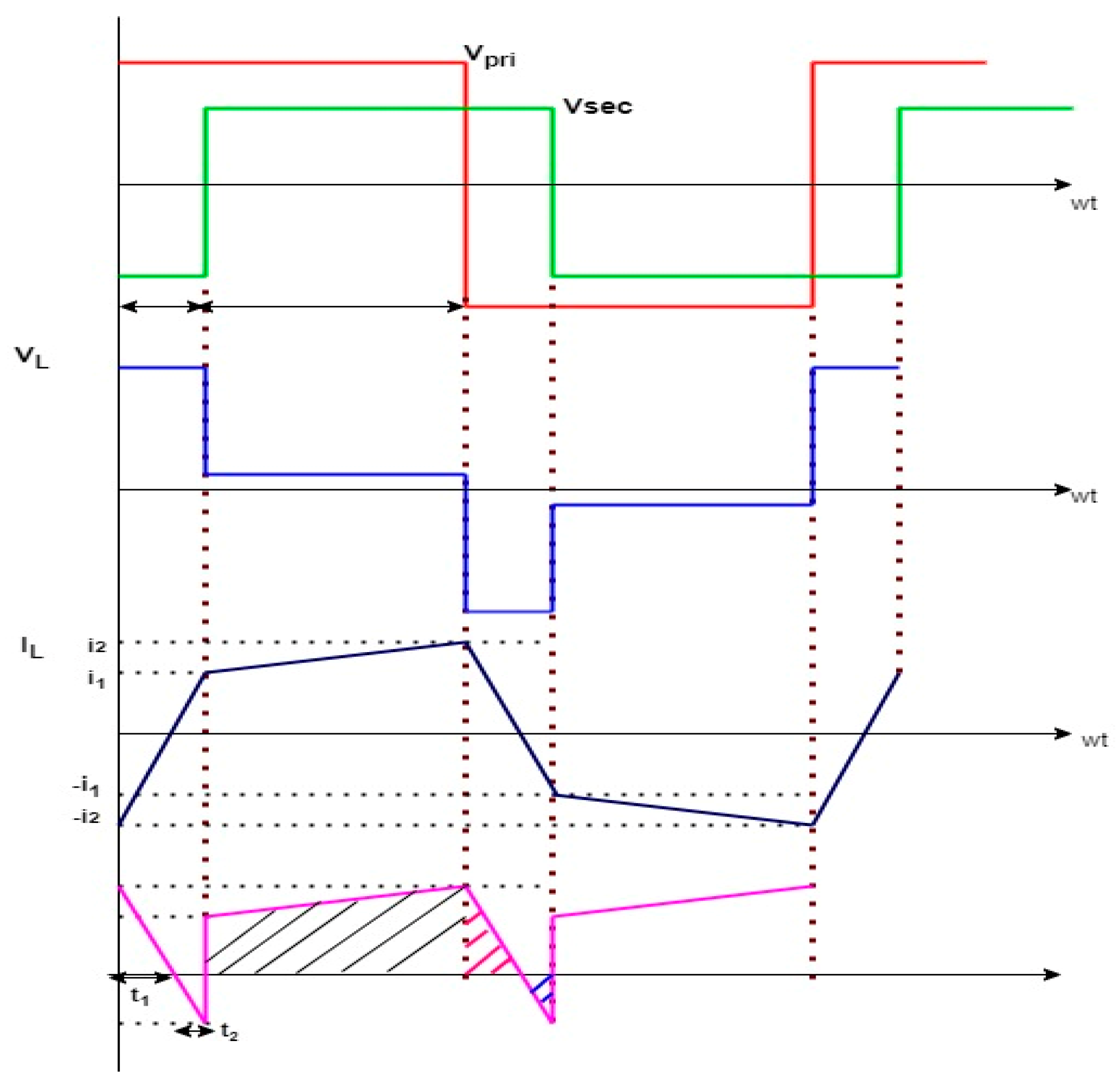
The variables Vpri and Vsec denote the sending and receiving end voltages, respectively, across the HFT. In Figure 2, the primary, secondary, and inductor currents of DAB are depicted. Consequently, in the scope of mathematical modelling, our analysis will be constrained to the first half of the waveform.
The average output current is given by
I o u t = Q T s 2
The output power is given by
P o u t = V o u t I o u t
From Figure 2, the total charge is calculated by the area under the switch current.
Q = a r e a 1 + a r e a 2 a r e a 3
The currents i1 and i2 are defined as
i 1 = t 1 V p r i + V s e c / n L k
i 2 = t 2 V p r i + V s e c / n L k
where φ = t 1 + t 2 .
Substituting the Equations (4) and (5) in (3) gives
Q = φ T s 2 φ V p r i L k
Substituting the Equations in (1) and (2) gives the output power, and it is defined as follows:
P o u t = V p r i V s e c φ ( 1 φ ) 2 n L k f s
Figure 3 shows the modes of operation of the converter. The operation of the DAB is divided into 4 modes based on the inductor current waveform shown in Figure 2. In mode-1, as shown in Figure 3a, the inductor current is both positive and negative, and the slope of the inductor current IL is defined as follows:
d i L d t = V p r i + V s e c L K  
During interval 2 i.e., mode-2, as shown in Figure 3b, the inductor current is still positive, the voltage across the primary side is positive, and the voltage across the secondary side is negative, leading to a difference in voltage, wherein the IL is defined as follows:
d i L d t = V p r i V s e c L K
As shown in Figure 3c under mode-3, the inductor current is starting to reduce Here, the voltage across the primary side is −Vpri. Hence, the IL is defined as follows:
d i L d t = ( V p r i + V s e c ) L K
Finally, in mode-4, as shown in Figure 3d, the inductor current continues to be in a negative state. During this interval, the primary voltage is −Vpri, and the secondary voltage is −Vsec. The IL is defined as follows:
d i L d t = V p r i + V s e c L K
During the transition from interval 1 to interval 2, the primary switches S1 and S4 are continuously on, and there exists a small amount of dead time where the ZVS operation takes place by discharging the inductor energy and charging the MOSFET capacitance in the secondary side. The switches S5 and S8 turn on at the ZVS condition. Similarly, in the transition from interval 2 to interval 3, the secondary switches S5 and S8 are continuously on, and the transition from S2, S3 to S1, S4 takes place at the ZVS condition [53]. Table 1 briefs the converter specification chosen.

3. Control Architecture

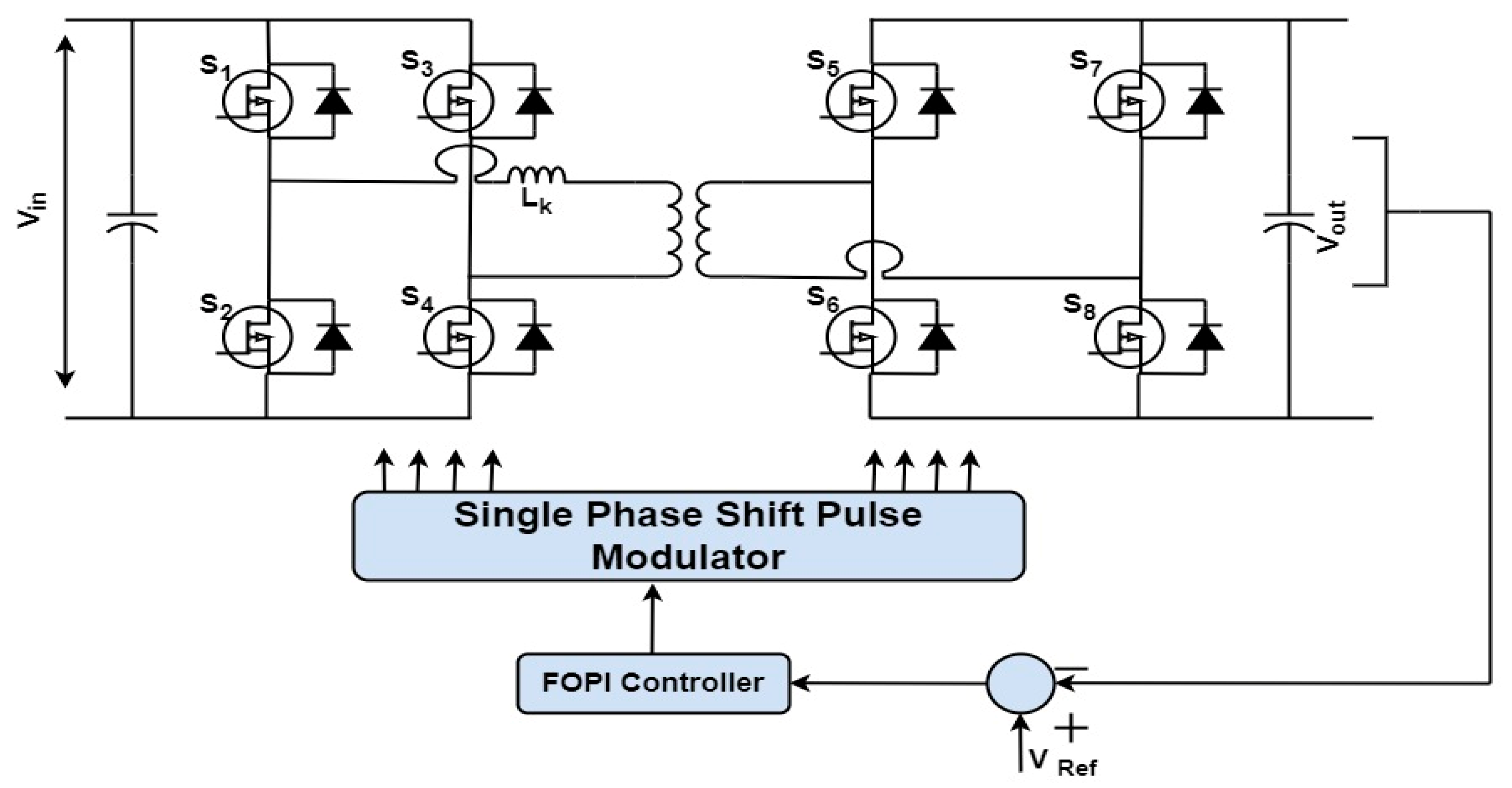
The output DC voltage of the DAB for the EV application must be properly controlled in accordance with the specifications. A controller based on FOPI is suggested here, which lowers the steady-state error and maintains voltage under load and line fluctuation. The system setup with the FOPI controller is displayed in Figure 4. A FOPI controller built using negative feedback for the output voltage loop is used in this design. Equation (7) is used to derive the analytical model, guiding the output voltage and phase shift. A reference output voltage is used to compare the output voltage that is being monitored. The error that results is then fed into the FOPI controller, which converts it into the appropriate phase shift value after processing it. The devices received the matching switching signals.

3.1. Fractional-Order PI Controller (FOPI)

In recent years, fractional controllers that employ fractional-order derivatives and integrals have gained more recognition because of their capacity to provide a strong performance, even amid the plant uncertainties and changes in gain. The general PID controller expression is defined by
u t = K p e t + 1 T i o t e τ d τ + T d d e t d t
In this case, u(t), e(t) are the control and error signals respectively, and the controller parameters Kp, Ki, and Kd, are the proportional gain, integral, and derivative constants, respectively.
Generalization of the integer order of Equation (12) leads to the Fractional-Order PI controller, which is defined as follows:
u t = K p e t + 1 T i D λ e t + T d D µ e ( t )
where λ , µ Ʀ are the non-integer values denoting the integral and derivative, and D is the fractional operator defined as Riemann–Liouville [34].
D n f t = 1 Γ ( n ) 0 t f ( y ) ( t y ) n 1 d y
n is a non-integer order, and Γ is the gamma function.
The Riemann–Liouville explanation is frequently employed for integrals and fractional-order derivatives. The fractional integral and derivative terms are defined as follows:
D t λ f t = 1 Γ ( λ ) 0 t t λ λ 1 f τ d τ
a D t λ f t = 1 Γ ( n λ ) d n d t n 0 t f ( τ ) ( t τ ) λ n + 1 d τ
When evaluating a FOPI controller when the error signal (ess) and control signal (uss) are both constant, the integral part’s main objective is to eliminate the steady-state inaccuracy completely [35]. The control signal is given as
u s s = K p e s s + e s s T i t λ Γ ( λ + 1 )
From the block diagram shown in Figure 5, the control signal obtained is
u t = K p e t + I
where
I = U s 1 1 + s λ T i
On simplifying,
I = K p 1 T i D λ e ( t )
Substituting in Equation (18) gives us
u t = K p ( e t + 1 T i D λ e t )
The FOPI controller’s transfer function, as determined by the Laplace transform, is as follows:
G s = K p + K i s λ
Figure 6 displays the schematic diagram of a voltage controller based on a FOPI controller.

3.2. Mathematical Modelling

To derive the system transfer function as depicted in Figure 6, state space modelling is carried out, considering the inductor current IL and the output capacitor voltage VC as state variables. The state space equation for the system is defined as follows:
X ˙ = A x + B u
Y = C x + E u
Considering mode-I, it is defined by
I L ˙ V C ˙ = 1 r l + R R 2 R + r c L 1 L R R + r c 1 C R R + r c 1 C ( R + r c ) I L V C + 1 L 0 V D C N 2 N 1
Similarly, for mode-II, it is defined by
I L ˙ V C ˙ = 1 r l + R R 2 R + r c L 1 L R R + r c 1 C R R + r c 1 C ( R + r c ) I L V C + 1 L 0 V D C N 2 N 1
The inductor current waveform is co-symmetric. Equations (25) and (26) describe the converter operational states.
The output voltage V o ( s ) (i.e., V c ) to phase shift ratio D ( s ) transfer function, found by substituting the design parameters, is given by
V o ( s ) D ( s ) ~ = 2.087 e 10 s + 4.175 e 22 5.243 e 8 s 2 + 4.178 e 15 s + 4.175 e 22
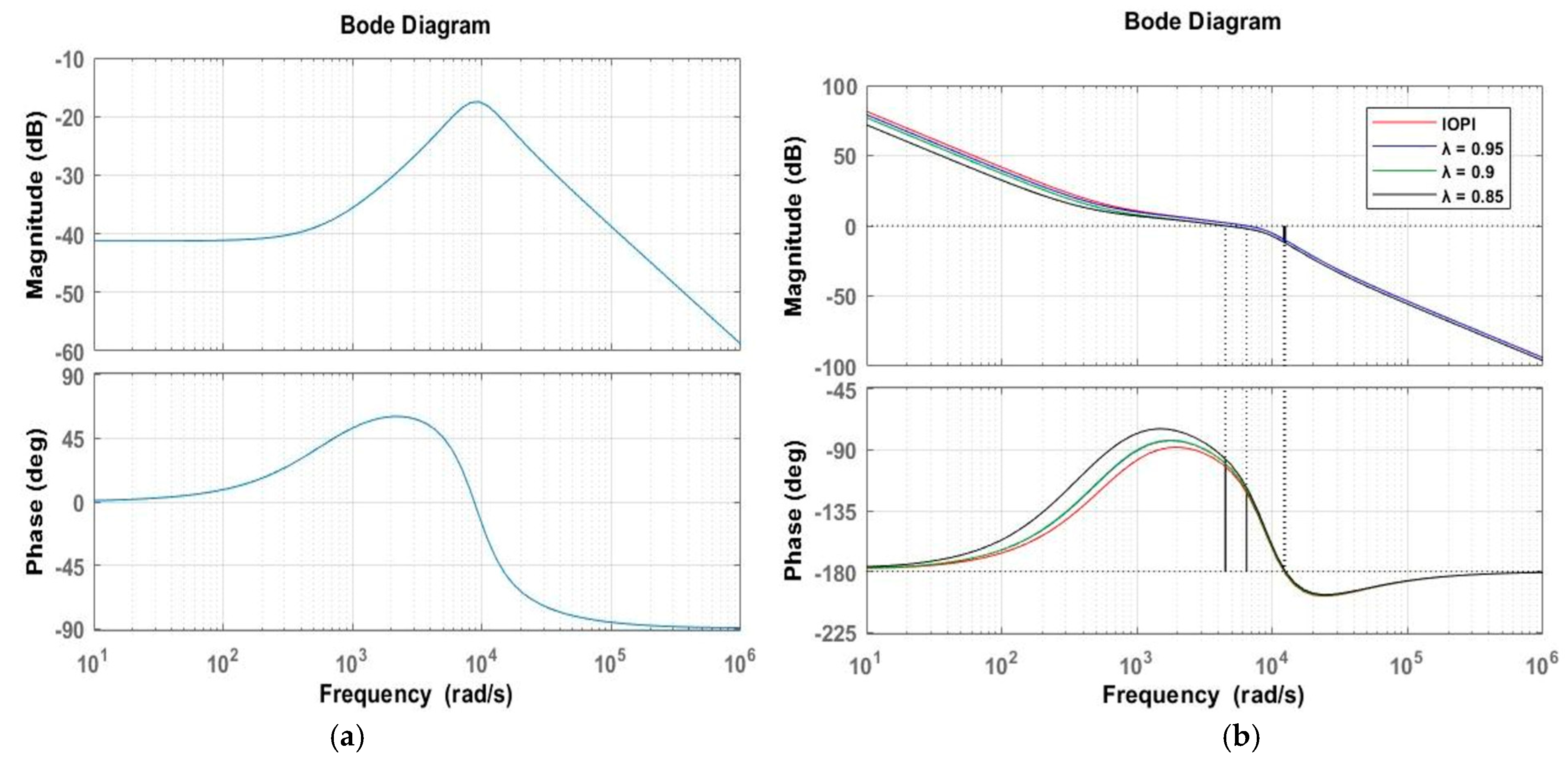
Figure 7 presents the bode responses of the system under different conditions, as follows: without a closed-loop controller (Figure 7a) and with classical PI and FOPI controllers (Figure 7b). The critical parameters, gain margin (GM) and phase margin (PM), play a significant role in assessing the stability and robustness of control systems. In Figure 7b, where the FOPI controller is applied, the fractional integral component (λ) in the transfer function is systematically adjusted within the range of 0.85 < λ < 0.95. The plot illustrates noticeable changes in the frequency response’s slope and shape. The systematic tuning of the fractional-order, represented by the varied λ, shows that optimizing the system’s behavior is significant. The higher GM and PM observed in Figure 7b signify improved stability and robustness against uncertainties or variations within the system by reducing the overshoot, settling time, and other performance indices as listed below in the upcoming section.
Importantly, the system’s performance, as gauged by GM and PM, exhibits enhancements compared to the classical PI controller. Table 2 illustrates the enhancement in GM and PM under variation in λ, compared to the conventional PI controller. The findings indicate that the FOPI controller facilitates an efficient approach, which improves the control system performance as demonstrated by the changes in the frequency response characteristics.

3.3. Tuning FOPI Controller for DAB

Five tuning parameters are included in the fractional-order controller. For the DAB application, the differential aspect is ignored, and the non-integer integral component is prioritized. Using the FOMCON toolbox, the Nelder–Mead approach is utilized to efficiently tune this controller [55]. This approach, which is classified as a probabilistic optimization strategy, deals with the problem of locating locations in a search space that coincides with an objective variable’s intended value. First, an n-dimensional triangle, or simplex, is produced at random to start the optimization process. The simplex moves or reshapes itself one vertex at a time throughout each iteration to find the best possible location inside the search space. At each step, the present simplex is improved little by little, and the algorithm chooses the one that moves it to a more advantageous domain region. The vertex of the simplex that produces the highest desired objective value is returned once the optimization process gets underway.
This approach has three steps, as follows: ordering, computing the central point, and rearrangement. Every point is arranged or sorted so that the last point is the highest and the first point is the lowest.
Let l, m, and n represent the first (worst), second (worst), and final (best) points index, respectively. Ordering is given by the following Equation (28) for computing the central point (c):
c = 1 n i l x i
The most important phase is the transition, which comes after. One of the following processes can lead to improvement: reflection, expansion, contraction, or shrinking and contracting. The first type of transformation to be tried is the reflection. It is defined in Equation (29), and may be used to compute the reflected point.
x r = n + α ( c x l )
x r is a point on the line connecting c and x l , positioned from a distance x l , where α is the reflection parameter, and it is assigned to one. As a result, the simplex is moved away from the area surrounding the suboptimal. We take a slight detour towards it from c in the hopes of arriving at a better option.
The expanded point ( x e ) is calculated using the Equation (30).
x e = c + γ ( x r c )
γ is the expansion parameter, which is mostly assigned to two, and it checks whether the computed reflection point has been worse; if it has, then the previously determined direction would not be an appropriate follow-up. In these situations, the simplex contracts inward. The contraction point is defined by Equation (31).
x c = c + β ( x p c )
Shrink contraction comes after the contraction step, and we redefine the complete simplex in this case, keeping the best point ( x r ) and summarizing the rest in relation to it, as well as the points that came before it. Equation (8) will now define the jth new point, as follows.
x j = x r + δ ( x j x r )
where δ is the shrinkage parameter, and it is set to 0.5 in most cases. In the hopes of converging to the best neighborhood, this pushes every point in the simplex in the direction of the current best point, causing the particle to travel in the simplex in that direction. When the minimal size restriction of the simplex is met, the number of iterations is reached; however, if the current best solution is above a tolerable threshold, the optimization will come to an end.
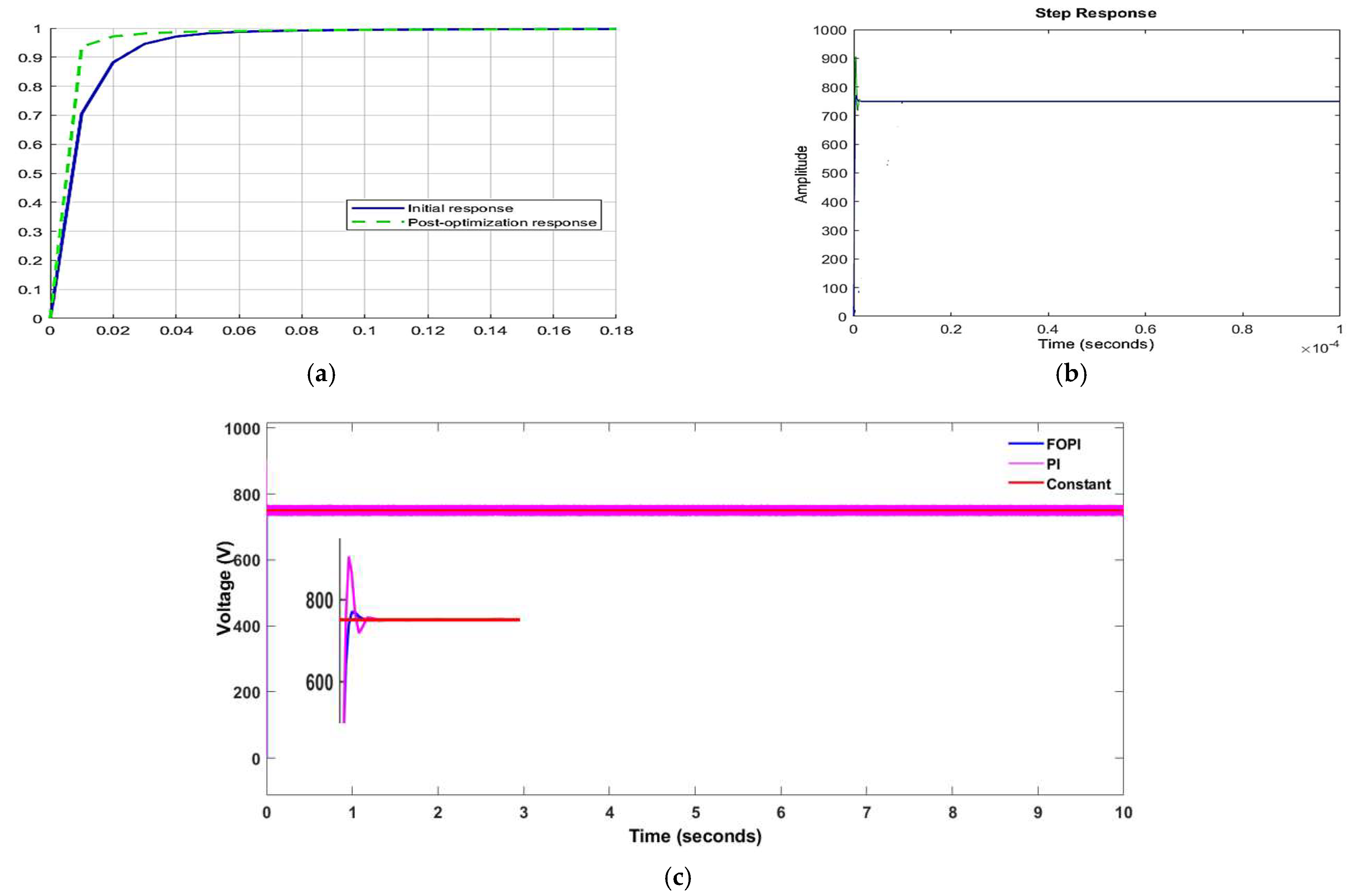
Figure 8a shows the response of the FOPI controller using the Nelder–Mead approach. From the Figure, we can observe that the post optimization response is better than the initial response, with a fixed range of Kp, Ki, and λ value. Figure 8b shows the step response of the classical PI and the FOPI controller. From the Figure, we can observe that the FOPI has a lesser overshoot with a fast settling response, compared to the classical PI controller. Figure 8c shows the overall response of the system, comparing FOPI, PI, and the reference value.

4. Results and Analysis

The simulation was performed based on the model specification, considering the Fractional-Order PI controller as well as the classical PI controller for constant load, step load variation, and line variation. The case studies listed below are considered for analysis.
  • Explains the performance under constant rated load, as well as the overshoot and settling time analysis.
  • Displays the system’s dynamic performance under line fluctuation.
  • Explains the system’s dynamic performance under load fluctuation. In every case, the performance of the FOPI is contrasted with that of the conventional PI controller.
  • Explains the effect of λ’s value over the FOPI controller regarding overshoot and settling duration for the same Kp, Ki values.
  • Explains the controller’s performance indices in terms of ISE, IAE, and ITAE values.

4.1. Performance Analysis under Constant Rated Load Using FOPI and Classical PI Controller

The system’s dynamic behavior is analyzed under a constant rated load of 1.563 ohms, with an input voltage of 750 V. Figure 9 and Table 3 show the dynamic performance of the converter using both FOPI and the classical PI controller for Kp, Ki, and λ values.
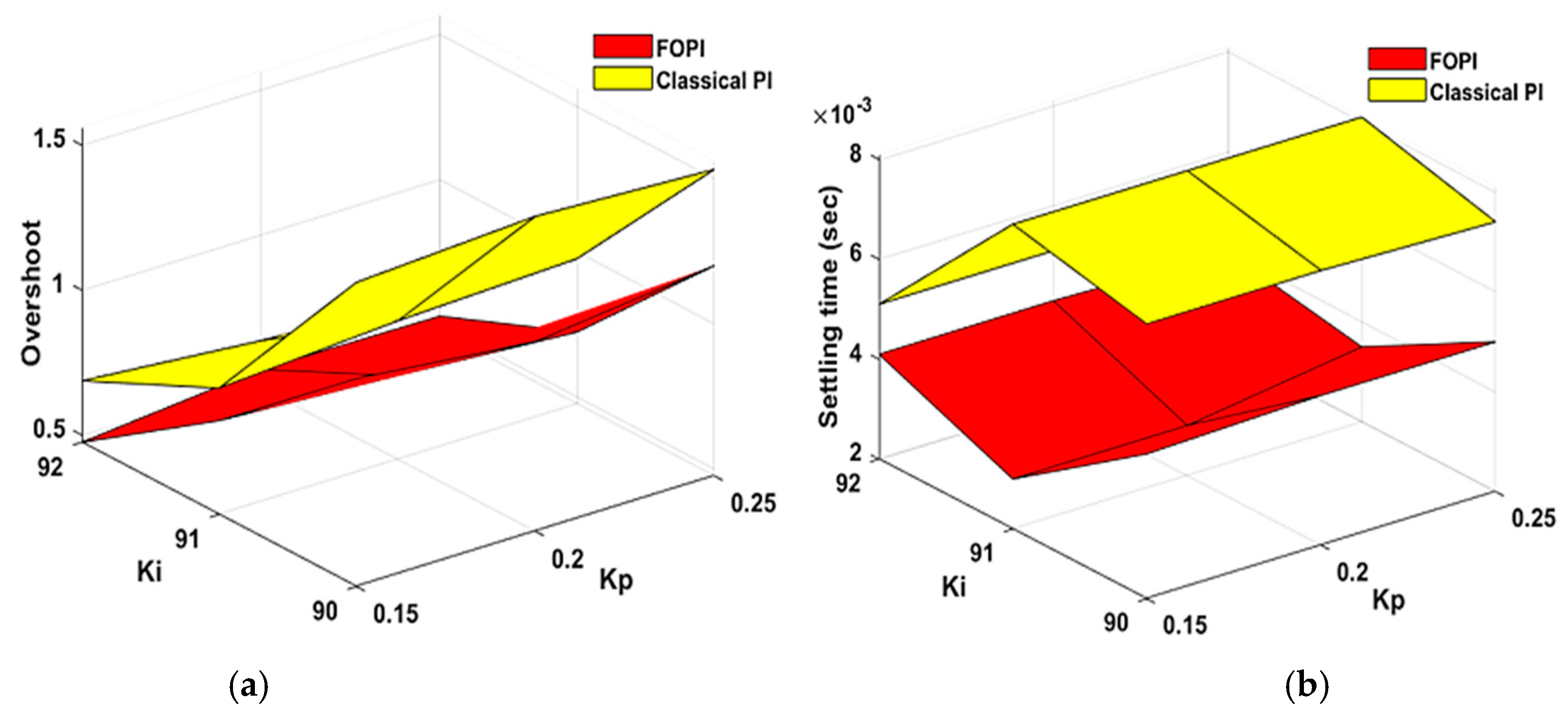
The proportional and integral terms are varied in the range of 0.1 < Kp < 0.4 and 90 < Ki < 94. The performances of the FOPI and traditional PI controllers for a given λ value are displayed in Figure 10 in terms of overshoot and settling period analysis.
Figure 10 shows that the FOPI has a lesser overshoot and settling time relative to the classical PI for the fixed λ value. The time-domain parameters’ values are listed in Table 3.

4.2. Steady-State Performance of the System under Load Variation

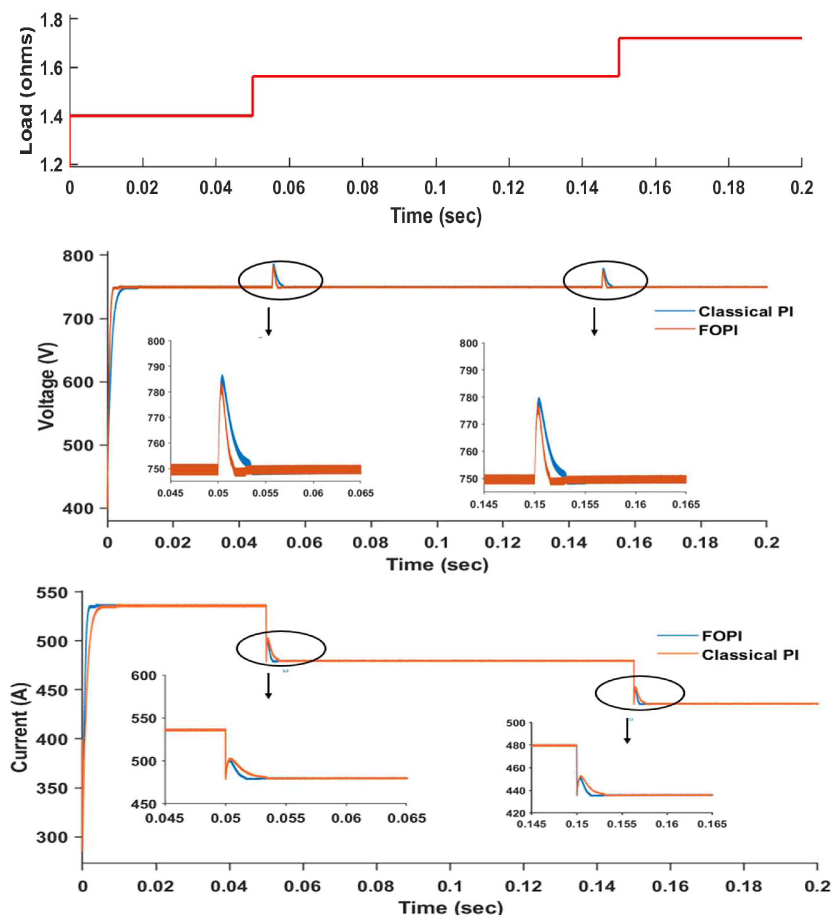
This case study presents the controllers’ performance under load variation. Figure 11 shows the controllers’ performance under load variation, and variation in the load is defined as follows:
l o a d =   1.34   ,   0 < t < 0.05 1.563   ,   0.05 < t < 0.15 1.723   ,   0.15 < t < 0.2  
Figure 11 illustrates how the FOPI controller transitions among operating points more quickly, and with less overshoot than the traditional PI controller.
Under load variation, the performance of the controller with respect to the settling time and the voltage drop at the output is listed in Table 4. From the analysis, we can observe that FOPI is more efficient than the classical PI controller under the various performance parameters.

4.3. Steady-State Performance of the System under Line Variation

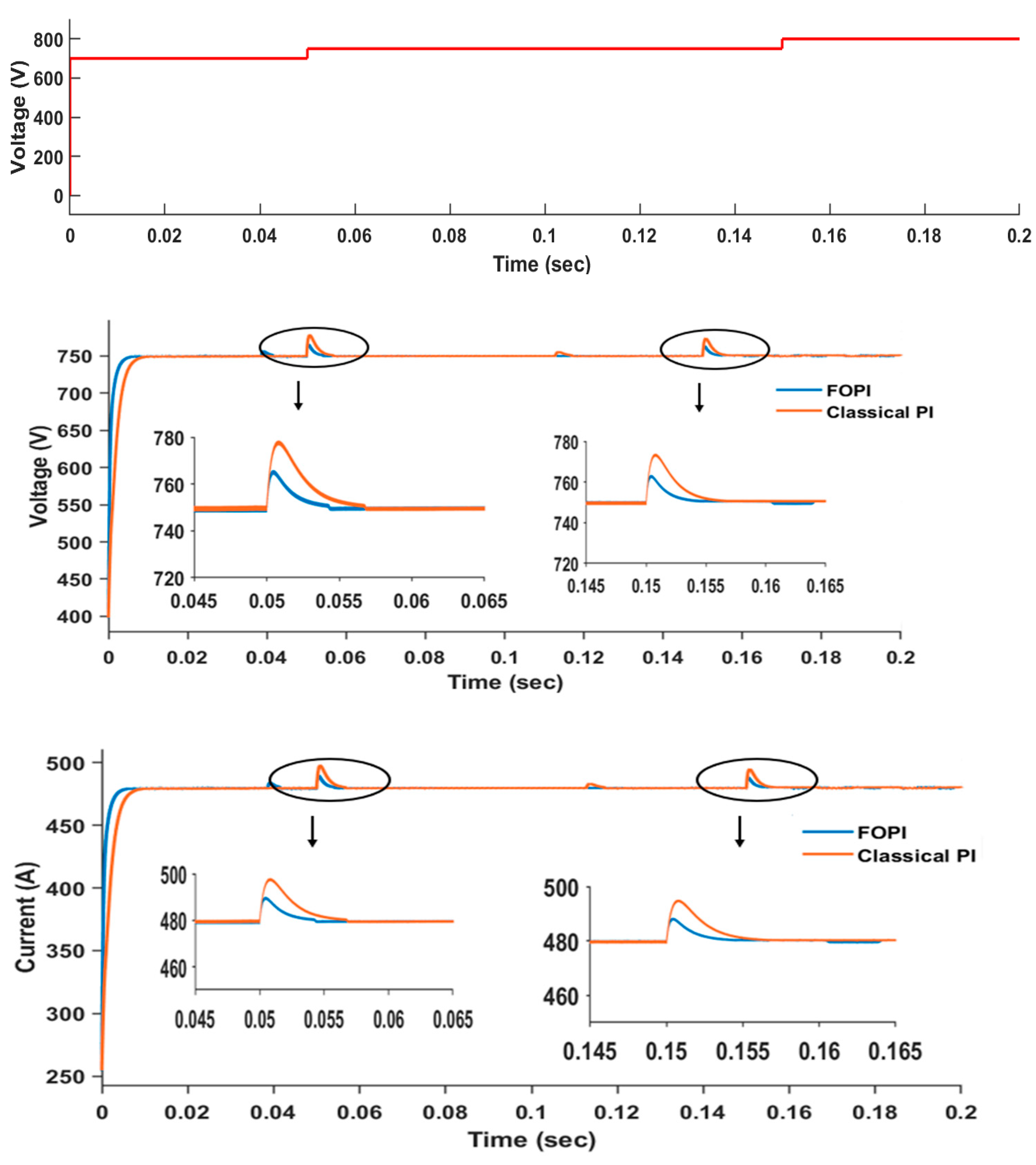
This case study presents the controllers’ performance under line variation. Figure 12 shows the controllers’ performance under line variation of 700 V, rated input 750 V, and 800 V; and the variation in the line is defined as follows:
I n p u t   v o l t a g e = 700   V ,   0 < t < 0.05 750   V ,   0.05 < t < 0.15 800   V ,   0.15 < t < 0.2
Figure 12 shows the outcome of the controller performance under input voltage variation that was carried out. In comparison to a standard PI controller, the output voltage transition between operating points for the FOPI controller exhibits far less overshoot and settles more quickly.

4.4. Performance Analysis of FOPI Controller under Different λ Values

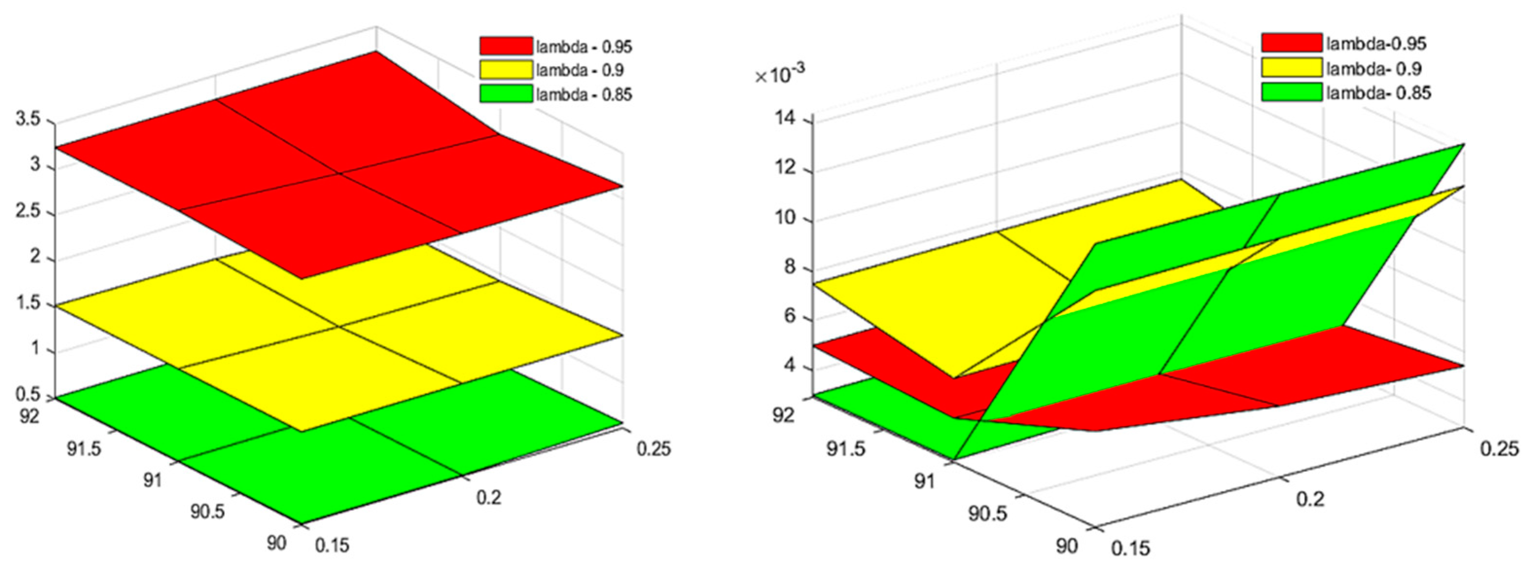
Figure 13 illustrates how the λ value affects the FOPI controller. The impact of λ is examined in the DAB simulation with the FOPI controller; the values of λ are adjusted between 0.85 and 0.95. The overshoot is directly impacted by the fractional integral value; as the value increases, the overshoot value increases as well, although settling time decreases with rising λ value. To cut down on overshoot and settling time in comparison to a traditional PI controller, the ideal λ value is selected.

4.5. Performance Evaluation of the Controllers

The generally used performance criteria in stability analysis includes the following parameters:
Integral Square Error (ISE) is defined as follows:
I S E = 0 t e ( t ) 2 d t
ISE computes the cumulative squared error over time. The main objective of the controllers is to minimize the parameter to an optimized value.
Integral Absolute Error (IAE) is defined as follows:
I A E = 0 t e ( t ) d t
IAE provides a measure of the cumulative absolute deviation of the process variable from the setpoint over a given period. It is used to assess the overall performance and accuracy of a control system, and it can be useful in tuning controllers for improved performance.
Integral Time weighted Absolute Error (ITAE) is defined as follows:
I T A E = 0 t t e ( t ) d t
The inclusion of the factor t in the integral gives more weight to errors that occur earlier in the process, emphasizing the importance of minimizing early deviations from the setpoint.
The analysis results of the performance indices mentioned above are shown in Table 5, utilizing both FOPI and the classical PI controller. It is evident from the table that the FOPI produces better results than the classical PI.
Table 6 shows the performance of the controller, validated with the work cited in [46]. From the analysis, the proposed controller is shown to be superior by achieving better or comparable performance metrics (lower overshoot and ITAE), with a simpler system. Lower complexity typically translates to easier implementation, reduced computational requirements, lower costs, and potentially higher reliability due to fewer points of failure.
Figure 14 shows the charging of the battery performance using the proposed controller and MATLAB/Simulink. For analysis, the battery SOC percentage is considered to be 70% at the nominal voltage of 750 V. The battery charges to 2% for a period of 30 s.

5. Conclusions

The paper presents Dual Active Bridge converter voltage regulation using a FOPI controller. The controllers’ resilience and effectiveness are tested in a variety of operating environments, including those with changeable input line supplies and loads. Simulation findings show that, in all operating conditions, the proposed FOPI controller performs better in terms of transient behavior than IOPI. As a result of the integral’s order flexibility, FOPI can minimize overshoot and settling time while still achieving the intended result. Ultimately, the performance evaluation is assessed using metrics like ITAE, ISE, and IAE. The analysis leads to the conclusion that FOPI outperforms IOPI.

Author Contributions

Conceptualization, D.T. and D.K.; data curation, M.L.K.; formal analysis, D.K.; investigation, D.K.; methodology, D.T. and D.K.; project administration, D.K. and M.L.K.; resources, D.T.; software, D.T.; supervision, D.K.; validation, D.K. and M.L.K.; visualization, D.K.; writing—original draft, D.K. and D.T.; writing—review and editing, D.T., D.K. and M.L.K. All authors have read and agreed to the published version of the manuscript.

Funding

This research is funded by the AMRITA Seed Grant; Proposal ID: ASG2022075, Amrita Vishwa Vidyapeetham, India; proposal title: Autonomous E-Mobility Centre.

Data Availability Statement

The original contributions presented in the study are included in the article, further inquiries can be directed to the corresponding author.

Acknowledgments

The authors would like to express their gratitude to Amrita Vishwa Vidyapeetham for its support in facilitating this work, and to the University of Agder for their cooperation, which is made possible through the academic collaboration agreement between both universities.

Conflicts of Interest

The authors declare no conflicts of interest.

Nomenclature

VariablesDefinitionUnits
Vpri, VsecVoltage across primary and secondaryVolts (V)
LkLeakage inductorHenry (H)
Kp, KiProportional and integral constant
fswSwitching frequencyHertz (Hz)
PoutOutput powerWatt (W)
IoutOutput currentAmpere (A)
φ Phase shiftRadians

References

  1. Baha, M.A.A.; Thomas, H.B. Review of Hybrid, Plug-In Hybrid, and Electric Vehicle Market Modelling Studies. Renew. Sustain. Energy Rev. 2013, 21, 190–203. [Google Scholar]
  2. Eldho, R.P.; Deepa, K. A Comprehensive Overview on the Current Trends and Technological Challenges in Energy Storages and Charging Mechanism in Electric Vehicle. J. Green Eng. 2020, 10, 4679–6713. [Google Scholar]
  3. Sruthy, V.; Raj, B.; Preetha, P.K.; Ilango, K. SPV based Floating Charging Station with Hybrid Energy Storage. In Proceedings of the 2019 IEEE International Conference on Intelligent Techniques in Control, Optimization and Signal Processing (INCOS), Tamilnadu, India, 11–13 April 2019; pp. 1–6. [Google Scholar]
  4. Khalid, M.R.; Khan, I.A.; Hameed, S.; Asghar, M.S.J.; Ro, J.-S. A Comprehensive Review on Structural Topologies, Power Levels, Energy Storage Systems, and Standards for Electric Vehicle Charging Stations and Their Impacts on Grid. IEEE Access 2021, 9, 128069–128094. [Google Scholar] [CrossRef]
  5. Konara, K.M.S.Y.; Kolhe, M.L.; Ulltveit-Moe, N.; Balapuwaduge, I.A.M. Optimal utilization of charging resources of fast charging station with opportunistic electric vehicle users. Batteries 2023, 9, 140. [Google Scholar] [CrossRef]
  6. Mounica, M.; Rajpathak, B.A.; Kolhe, M.L.; Naik, K.R.; Moparthi, J.R.; Kotha, S.K. Piece-Wise Droop Controller for Enhanced Stability in DC-Microgrid-Based Electric Vehicle Fast Charging Station. Processes 2024, 12, 892. [Google Scholar] [CrossRef]
  7. Nandhini, V.; Bharathi, K.; Giri, S.; Sowvav, S. Energy Management of and Smart Control of Home Appliances. J. Phys. 2020, 1706, 012087. [Google Scholar] [CrossRef]
  8. Khaligh, A.; Dusmez, S. Comprehensive topological analysis of conductive and inductive charging solutions for plug-in electric vehicles. IEEE Trans. Veh. Technol. 2012, 61, 3475–3489. [Google Scholar] [CrossRef]
  9. Yilmaz, M.; Krein, P.T. Review of Battery Charger Topologies, Charging Power Levels, and Infrastructure for Plug-In Electric and Hybrid Vehicles. IEEE Trans. Power Electron. 2013, 28, 2151–2169. [Google Scholar] [CrossRef]
  10. Raghavan, S.S.; Onar, O.C.; Khaligh, A. Power Electronic Interfaces for Future Plug-In Transportation Systems. IEEE Power Electron. Soc. Newsl. 2010, 24, 23–26. [Google Scholar]
  11. Biya, T.S.; Sindhu, M.R. Design and Power Management of Solar Powered Electric Vehicle Charging Station with Energy Storage System. In Proceedings of the 2019 3rd International conference on Electronics, Communication and Aerospace Technology (ICECA), Coimbatore, India, 12–14 June 2019; pp. 815–820. [Google Scholar]
  12. Erb, D.C.; Onar, O.C.; Khaligh, A. Bi-directional Charging Topologies for Plug-in Hybrid Electric Vehicles. In Proceedings of the 2010 Twenty-Fifth Annual IEEE Applied Power Electronics Conference and Exposition (APEC), Palm Springs, CA, USA, 21–25 February 2010; pp. 2066–2072. [Google Scholar]
  13. Deepti, T.; Deepa, D.D.K.; Anoop, A. High Power Bi-Directional Converter for Electric Vehicle Application. In Proceedings of the 2023 3rd International Conference on Intelligent Technologies (CONIT), Hubli, India, 23–25 June 2023. [Google Scholar]
  14. Deepti, T.; Deepa, K.; Stonier, A.A.; Peter, G.; Anoop, A.; Ganji, V. Development and Efficiency Analysis of Dual Active Bridge Converter Employing SiC Devices using TMS 320F280039. IET Circuits Devices Syst. J. 2024. [Google Scholar]
  15. Aia, X.; Zuob, D.; Zhangc, Y. Modelling and Simulation of Dual-Active-Bridge Based on PI Control. J. Phys. Conf. Ser. 2022, 2221, 012007. [Google Scholar] [CrossRef]
  16. Babokany, A.S.; Jabbaril, M.; Shahgholian, G.; Mahdavian, M. A Review of Bidirectional Dual Active Bridge Converter. In Proceedings of the 2012 9th International Conference on Electrical Engineering/Electronics, Computer, Telecommunications and Information Technology, Phetchaburi, Thailand, 16–18 May 2012; pp. 978–981. [Google Scholar]
  17. Maroti, P.K.; Padmanaban, S.; Bhaskar, M.S.; Ramachandaramurthy, V.K.; Blaabjerg, F. The state-of-the-art of power electronics converters configurations in electric vehicle technologies. Power Electron. Devices Compon. J. 2021, 1, 100001. [Google Scholar] [CrossRef]
  18. Coelho, S.; Sousa, T.J.; Monteiro, V.; Machado, L.; Afonso, J.L.; Couto, C. Comparative Analysis and Validation of Different Modulation Strategies for an Isolated DC-DC Dual Active Bridge Converter. In Sustainable Energy for Smart Cities: Second EAI International Conference, SESC 2020, Viana do Castelo, Portugal, 4 December 2020; Proceedings 2; Springer International Publishing: Berlin/Heidelberg, Germany, 2021. [Google Scholar]
  19. Liu, P.; Shanxu, D. A hybrid modulation strategy providing lower inductor current for the DAB converter with the aid of DC blocking capacitors. IEEE Trans. Power Electron. 2019, 35, 4309–4320. [Google Scholar] [CrossRef]
  20. Corti, F.; Bertolini, V.; Reatti, A.; Cardelli, E.; Giallongo, M. Comparison of Control Strategies for Dual Active Bridge Converter. In Proceedings of the 2022 IEEE 21st Mediterranean Electrotechnical Conference (MELECON), Palermo, Italy, 14–16 June 2022. [Google Scholar]
  21. Calderon, C.; Barrado, A.; Rodriguez, A.; Alou, P.; Lazaro, A.; Fernandez, C.; Zumel, P. General Analysis of Switching Modes in a Dual Active Bridge with Triple Phase Shift Modulation. Energies 2018, 11, 2419. [Google Scholar] [CrossRef]
  22. Turzyński, M.; Bachman, S.; Jasiński, M.; Piasecki, S.; Ryłko, M.; Chiu, H.-J.; Kuo, S.-H.; Chang, Y.-C. Analytical Estimation of Power Losses in a Dual Active Bridge Converter Controlled with a Single-Phase Shift Switching Scheme. Energies 2022, 15, 8262. [Google Scholar] [CrossRef]
  23. Trivedi, S.S.; Sant, A. Comparative analysis of dual active bridge dc–dc converter employing Si, SiC and GaN MOSFETs for G2V and V2G operation. Energy Rep. 2022, 8, 1011–1019. [Google Scholar]
  24. Podlubny, I. Fractional Order System and PID controller. IEEE Trans. Autom. Control 1999, 44, 208–214. [Google Scholar] [CrossRef]
  25. Gholami Khesht, H.; Davari, P.; Blaabjerg, F. Adaptive Control in Power Electronic Systems; Elsevier: Amsterdam, The Netherlands, 2021; pp. 125–147. [Google Scholar]
  26. Yang, M.; Liu, P. Research on Sliding Mode Control of Dual Active Bridge Converter Based on Linear Extended State Observer in Distributed Electric Propulsion System. Electronics 2023, 12, 3522. [Google Scholar] [CrossRef]
  27. Tiwary, N.; Naik, V.N.; Panda, A.K.; Narendra, A.; Lenka, R.K. Fuzzy Logic Based Direct Power Control of Dual Active Bridge Converter. In Proceedings of the 2021 1st International Conference on Power Electronics and Energy (ICPEE), Bhubaneswar, India, 2–3 January 2021. [Google Scholar]
  28. Fu, Y.; Jing, Z.; Ren, H.-P. Model predictive control for DAB under extended-phase-shift considering components uncertainty. IET Power Electron. 2023, 16, 1984–1995. [Google Scholar] [CrossRef]
  29. Fan, Y.; Shao, J.; Sun, G.; Shao, X. Proportional–Integral–Derivative Controller Design Using an Advanced Lévy-Flight Salp Swarm Algorithm for Hydraulic Systems. Energies 2020, 13, 459. [Google Scholar] [CrossRef]
  30. Balaji, B.; Krishnan KS, S.; Revathy, R.; Preetha, R. Fractional order PID controlled quasi Z-source inverter with front-line semiconductor material made of power electronics switches fed PMSM motor for EV applications. Mater. Today Proc. 2022, 69, 1322–1333. [Google Scholar] [CrossRef]
  31. Soriano-Sánchez, A.G.; Rodríguez-Licea, M.A.; Pérez-Pinal, F.J.; Vázquez-López, J.A. Fractional-Order Approximation and Synthesis of a PID Controller for a Buck Converter. Energies 2020, 13, 629. [Google Scholar] [CrossRef]
  32. Prajapati, S.; Garg, M.M.; Prithvi, B. Design of Fractional-Order PI controller for DC-DC Power Converters. In Proceedings of the 2018 8th IEEE India International Conference on Power Electronics (IICPE), Jaipur, India, 13–15 December 2018. [Google Scholar]
  33. Warrier, P.; Shah, P. Fractional Order Control of Power Electronic Converters in Industrial Drives and Renewable Energy Systems, A Review. IEEE Access 2021, 9, 58982–59009. [Google Scholar] [CrossRef]
  34. Al-Saggaf, U.; Mehedi, I.; Bettayeb, M.; Mansouri, R. Fractional-order controller design for a heat flow process. Proc. Inst. Mech. Eng. Part I J. Syst. Control Eng. 2016, 230, 680–691. [Google Scholar] [CrossRef]
  35. Monje, C.A.; Vinagre, B.M.; Feliu, V.; Chen, Y.Q. Tuning and auto-tuning of fractional order controllers for industry applications. Control Eng. Pract. 2008, 16, 798–812. [Google Scholar] [CrossRef]
  36. Monje, C.A.; Chen, Y.Q.; Vinagre, B.M.; Xue, D.; Feliu, V. Fractional-Order Systems and Controls. Fundamentals and Applications; Springer: Berlin/Heidelberg, Germany, 2010. [Google Scholar]
  37. Zheng, W.; Luo, Y.; Pi, Y.; Chen, Y. Improved Frequency-Domain Design Method for the Fractional Order proportional–integral–derivative controller optimal design: A case study of permanent magnet synchronous motor speed control. IET Control Theory Appl. 2018, 12, 2478–2487. [Google Scholar] [CrossRef]
  38. Tajjudin, M.; Rahiman, M.H.F.; Arshad, N.M.; Adnan, R. Robust Fractional-Order PI Controller with Ziegler-Nichols Rules. Int. J. Electr. Comput. Eng. 2013, 7, 1034–1041. [Google Scholar]
  39. Gude, J.J.; Kahoraho, E. Modified Ziegler-Nichols method for fractional PI controllers. In Proceedings of the 2010 IEEE 15th Conference on Emerging Technologies & Factory Automation (ETFA 2010), Bilbao, Spain, 13–16 September 2010. [Google Scholar]
  40. Valério, D.; Sá da Costa, J. Tuning of fractional PID controllers with Ziegler-Nichols-type rules. Signal Process. 2006, 10, 2771–2784. [Google Scholar] [CrossRef]
  41. Hekimoglu, B. Optimal Tuning of Fractional Order PID Controller for DC Motor Speed Control via Chaotic Atom Search Optimization Algorithm. IEEE Access 2019, 7, 38100–38114. [Google Scholar] [CrossRef]
  42. Kesarkar, A.A.; Selvaganesan, N. Tuning of optimal fractional-order PID controller using an artificial bee colony algorithm. Syst. Sci. Control Eng. 2015, 3, 99–105. [Google Scholar] [CrossRef]
  43. Keyser, D.; Muresan, C.I.; Ionescu, C.M. A novel auto-tuning method for fractional order PI/PD controllers. ISA Trans. 2016, 62, 268–275. [Google Scholar] [CrossRef] [PubMed]
  44. Adhul, S.V.; Ananthan, T. FOPID Controller for Buck Converter. Procedia Comput. Sci. 2020, 171, 576–582. [Google Scholar]
  45. Sánchez, A.G.S.; Soto-Vega, J.; Tlelo-Cuautle, E.; Rodríguez-Licea, M.A. Fractional-Order Approximation of PID Controller for Buck–Boost Converters. Micromachines 2021, 12, 591. [Google Scholar] [CrossRef] [PubMed]
  46. Dong, Z.; Yang, P.; Li, Q.; Zhang, M.; Chang, Y.; Wang, S. Fractional order modelling and optimal control of dual active bridge converters. Syst. Sci. Control Eng. 2024, 12, 2347886. [Google Scholar] [CrossRef]
  47. Ma, F.; Wang, X.; Deng, L.; Zhu, Z.; Xu, Q.; Xie, N. Multiport Railway Power Conditioner and Its Management Control Strategy with Renewable Energy Access. IEEE J. Emerg. Sel. Top. Power Electron. 2020, 8, 1405–1418. [Google Scholar] [CrossRef]
  48. Chen, J.; Zhao, Y.; Wang, M.; Wang, K.; Huang, Y.; Xu, Z. Power Sharing and Storage-Based Regenerative Braking Energy Utilization for Sectioning Post in Electrified Railways. IEEE Trans. Transp. Electrif. 2024, 10, 2677–2688. [Google Scholar] [CrossRef]
  49. Konara, K.M.S.Y.; Kolhe, M.L.; Ulltveit-Moe, N.; Balapuwaduge, I.A.M. Reliability Enhancement of Fast Charging Station under Electric Vehicle Supply Equipment Failures and Repairs. Energies 2023, 16, 2933. [Google Scholar] [CrossRef]
  50. Rao, J.V.G.R.; Venkateshwarlu, S. Soft-switching dual active bridge converter-based bidirectional on-board charger for electric vehicles under vehicle-to-grid and grid-to-vehicle control optimization. J. Eng. Appl. Sci. 2024, 71, 49. [Google Scholar] [CrossRef]
  51. Ataullah, H.; Iqbal, T.; Khalil, I.U.; Ali, U.; Blazek, V.; Prokop, L.; Ullah, N. Analysis of the Dual Active Bridge-Based DC-DC Converter Topologies, High-Frequency Transformer, and Control Techniques. Energies 2022, 15, 8944. [Google Scholar] [CrossRef]
  52. Taylor, A.; Lu, J.; Zhu, L.; Bai, K.; McAmmond, M.; Brown, A. Comparison of SiC MOSFET-based and GaN HEMT-based high-efficiency high-power-density 7.2 kW EV battery chargers. IET Power Electron. 2018, 11, 1849–1857. [Google Scholar] [CrossRef]
  53. Adireddy, R.; Pratap, K.N.G.A.; Himaja, T.; Murthy, K.V.S.R. Circuit analysis and modelling of dual active bridge bidirectional converter. Mater. Today 2022, 56, 3272–3275. [Google Scholar] [CrossRef]
  54. Eyvazi, H.; Alimohammadi, Z.; Sheikhi, A.; Adelighalehtak, Y.; Aliasghari, T.P. Analysis of dual active bridge-based on-board battery charger for electric and hybrid vehicles. Int. J. Sci. Res. Arch. 2024, 12, 216–230. [Google Scholar] [CrossRef]
  55. Padula, F.; Visioli, A. Tuning rules for optimal PID and fractional-order PID controllers. J. Process Control 2011, 21, 69–81. [Google Scholar] [CrossRef]
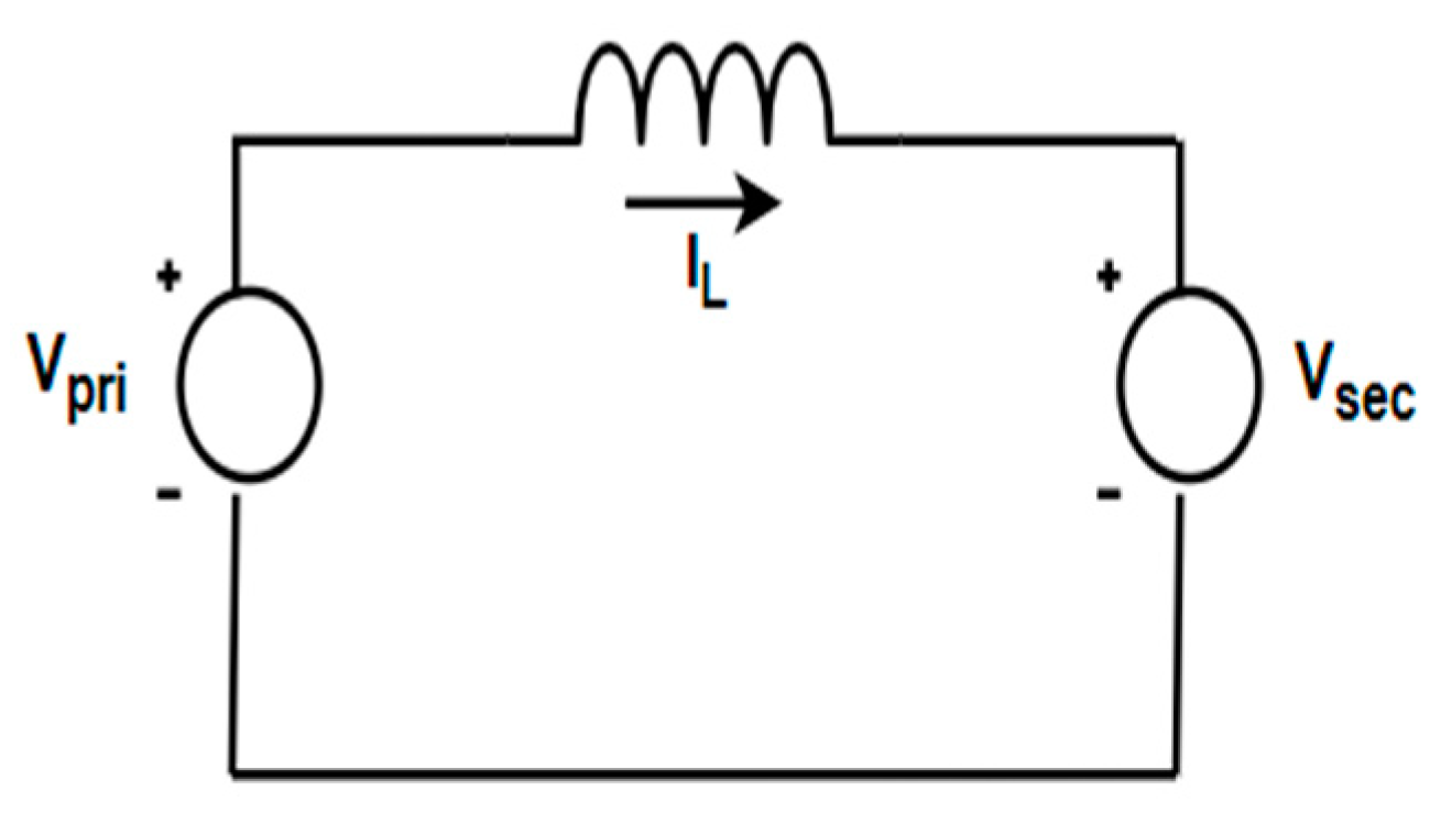
Figure 1. Equivalent circuit of DAB.
Energies 17 04312 g001
Figure 2. DAB’s voltage and current waveform controlled by SPS.
Energies 17 04312 g002
Figure 3. Modes of operation of DAB with the power flow. (a) Mode-1, (b) Mode-2 (c) Mode-3 (d) Mode-4.
Energies 17 04312 g003aEnergies 17 04312 g003b
Figure 4. System and control architecture.
Energies 17 04312 g004
Figure 5. Block diagram representation of FOPI.
Energies 17 04312 g005
Figure 6. FOPI closed-loop system.
Energies 17 04312 g006
Figure 7. Bode response of (a) system transfer function and (b) closed-loop transfer function (PI, FOPI).
Energies 17 04312 g007
Figure 8. (a) Optimization response using FOPI controller. (b) Step response of FOPI, PI controller. (c) Response of system.
Energies 17 04312 g008
Figure 9. Output voltage at rated load.
Energies 17 04312 g009
Figure 10. (a) Overshoot. (b) Settling time analysis of FOPI and classical PI controller.
Energies 17 04312 g010
Figure 11. Dynamic performance of FOPI, classical PI controller under load variation.
Energies 17 04312 g011
Figure 12. Dynamic performance of FOPI, classical PI controller under line variation.
Energies 17 04312 g012
Figure 13. Overshoot and settling time analysis for different λ values using FOPI controller.
Energies 17 04312 g013
Figure 14. Battery performance.
Energies 17 04312 g014
Table 1. Converter specifications.
ParametersValues
Input voltage750 V
Output voltage750 V
Turns ratio1
Switching frequency100 kHz
Inductor2.6 µH
Load1.563 Ω
Output current480 A
Output power360 kW
Table 2. Bode analysis of FOPI, classical PI.
ControllerGain Margin (dB)Phase Margin (deg)Lambda (λ)
IOPI9.5658.3Nil
FOPI9.8660.20.95
11.979.80.9
12.383.50.85
Table 3. Response analysis of FOPI, classical PI.
ParametersFOPIClassical PI
Overshoot (%)0.52540.5277
Settling time (ms)3.25.1
Rise time (ms)0.5570.958
Peak time (ms)18.4219.23
Steady-state error (%)0.040.072
Table 4. Load performance of FOPI, classical PI.
ControllerSettling Time (ms)Voltage Drop (%)
FOPI15.083.2
Classical PI20.54.8
Table 5. Performance indices of controller.
ControllerISEIAEITAE
FOPI16.670.39840.02101
Classical PI23.370.50740.02143
Table 6. Performance analysis of controller.
ParametersRef [46]FOPI
OvershootWithin 5% limit-1.33% (under line variation)
1.6% (under load variation)
ITAE0.02453 (PI controller)0.02143 (PI controller)
ComplexityHigher complexityLower complexity
Computational TimeMoreLesser
Disclaimer/Publisher’s Note: The statements, opinions and data contained in all publications are solely those of the individual author(s) and contributor(s) and not of MDPI and/or the editor(s). MDPI and/or the editor(s) disclaim responsibility for any injury to people or property resulting from any ideas, methods, instructions or products referred to in the content.