
Performance Analysis of Novel Direct-Condensation Heating Panels Integrated with Air Source Heat Pump System on Thermal Economy and System Efficiencies


Abstract
1. Introduction
1.1. Background Information
1.2. Direct-Condensation Heating Terminal
1.3. Objective of This Study
2. Experimental Procedure
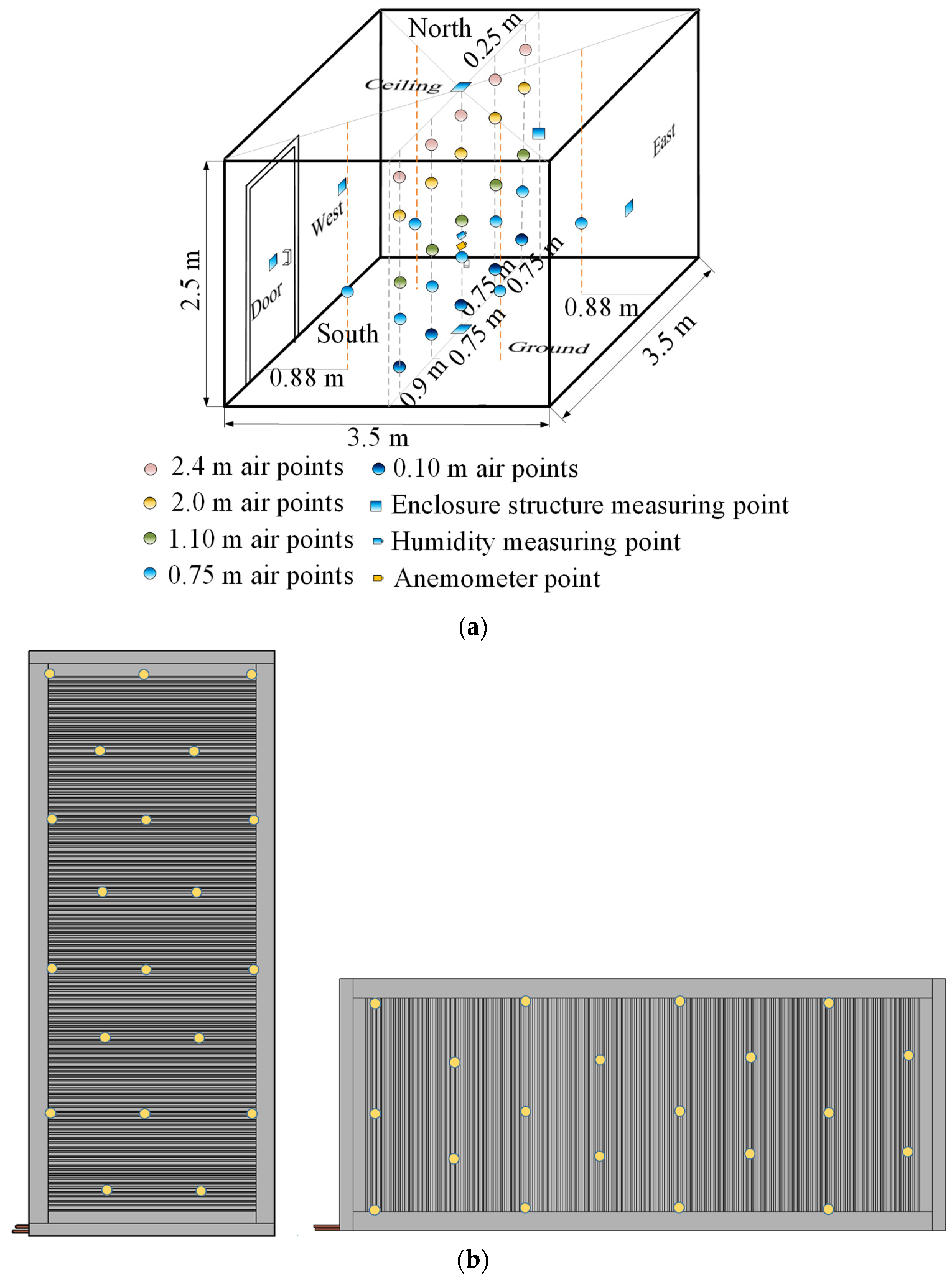
2.1. Experimental Site Description
2.1.1. System Description
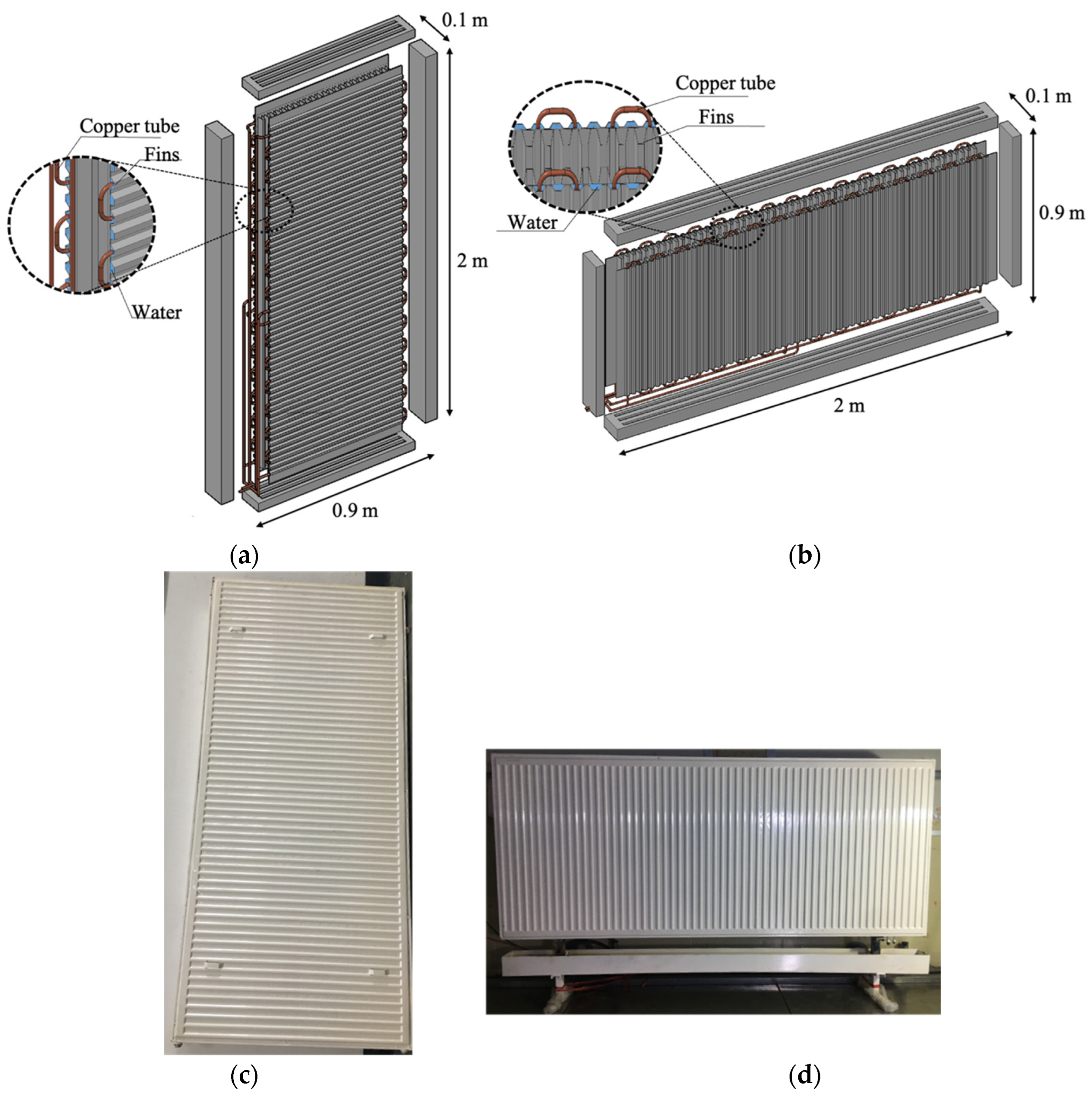
2.1.2. Detailed Heating Panel Description
2.2. Testing Scheme
2.3. Uncertainty Analysis
3. Evaluation Methodology
3.1. Thermal Comfort Evaluation
3.2. Thermal Economic Evaluation
3.3. System Efficiency Evaluation
3.3.1. Energy Efficiency
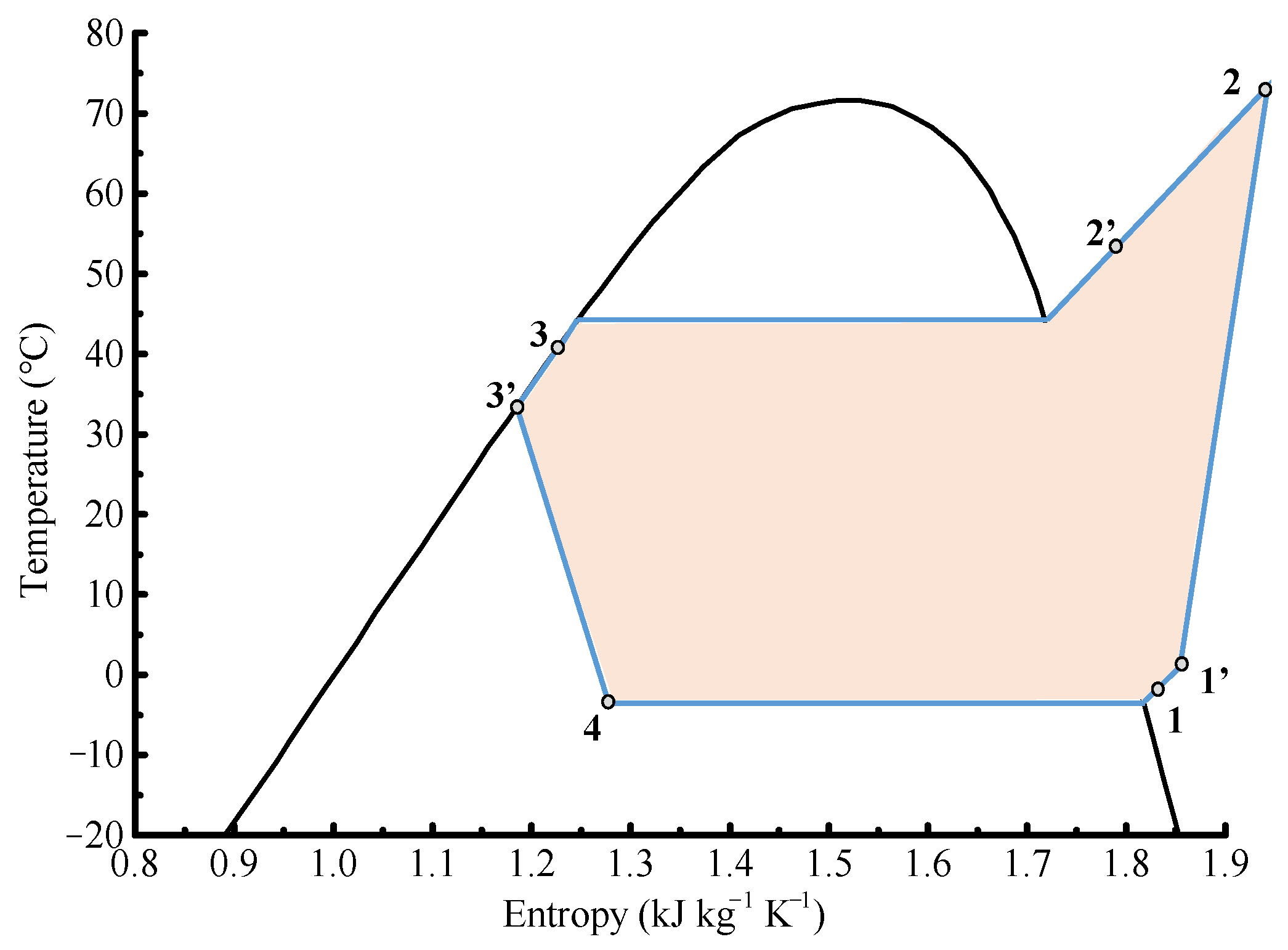
3.3.2. Exergy Efficiency
- (a)
- The system keeps a steady operation without chemical reactions;
- (b)
- The process from 3′ to 4 is isenthalpic (i.e., h3′ = h4);
- (c)
- The outdoor environment is considered as the dead state [31];
- (d)
- The power consumption of the outdoor fan is ignored in comparison with that of the compressor;
- (e)
- The pressure drop in the evaporator and condenser is ignored;
- (f)
- Air is treated as an ideal gas.
4. Results and Discussion
4.1. Thermal Comfort of the Proposed Heating Panels
4.1.1. Comparison with Previous Heating Terminals
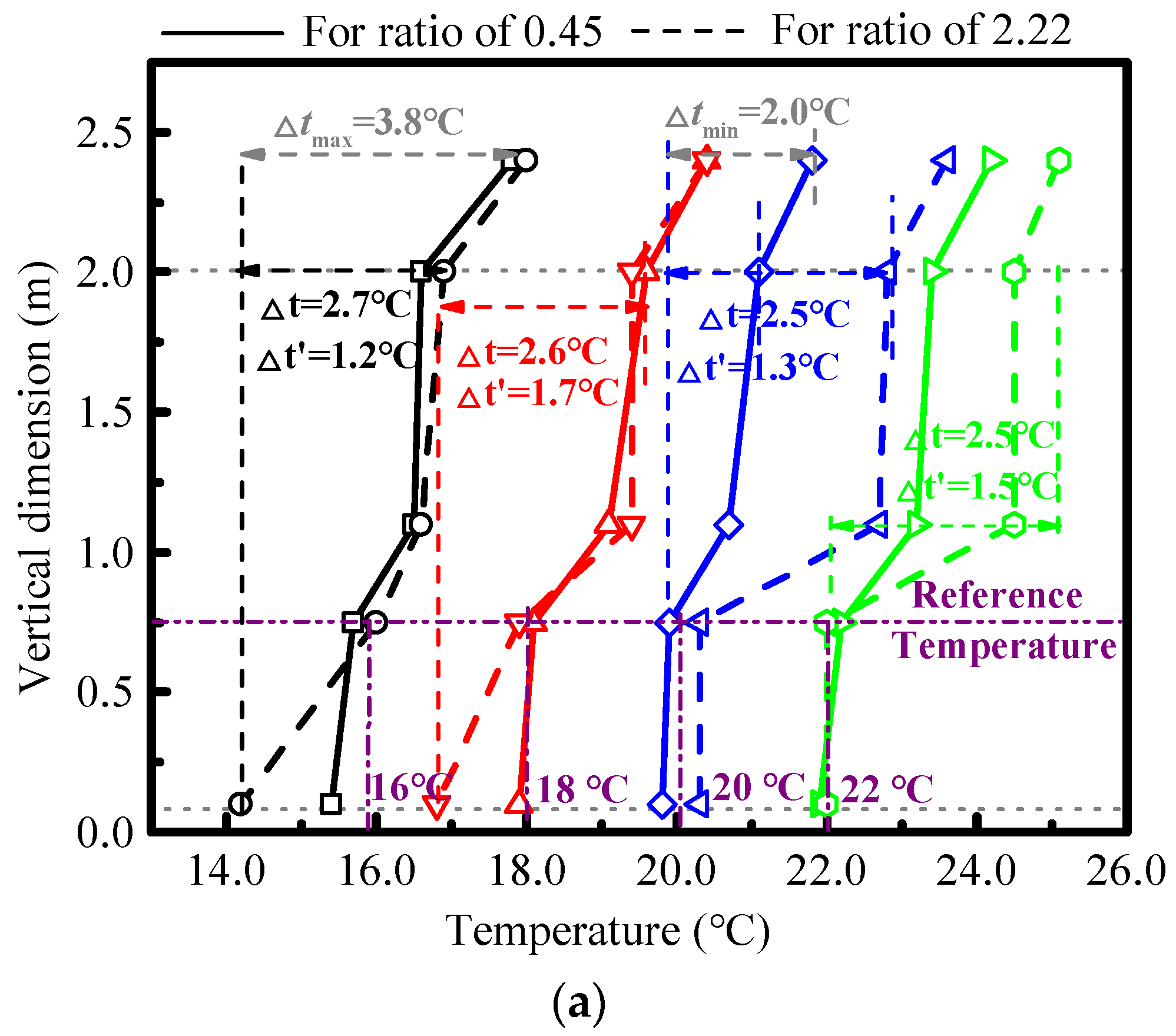
4.1.2. Comparison of the Proposed Heating Panels with Two Aspect Ratios
4.2. Heat Transfer Performance and Economy of the Proposed Heating Panels
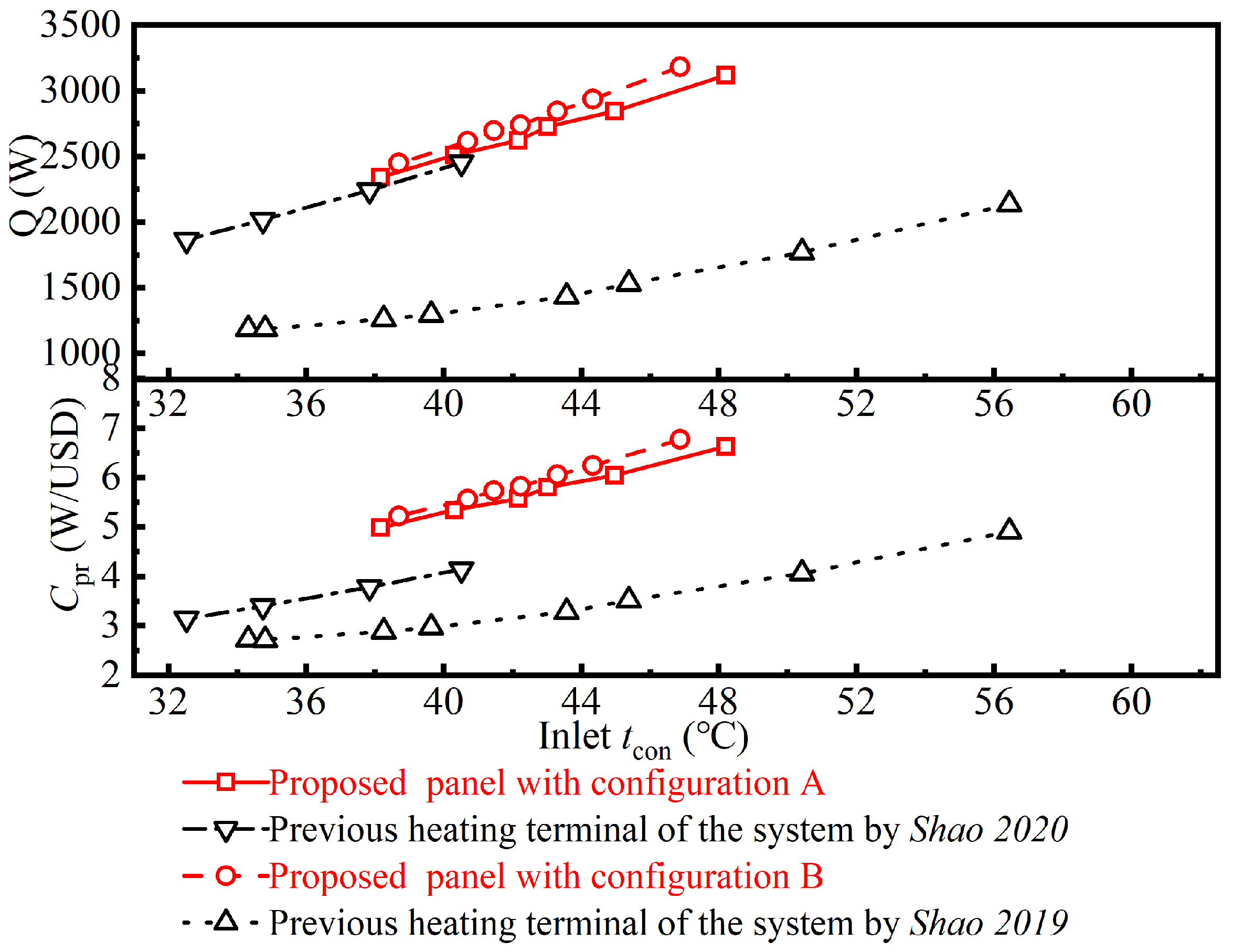
4.2.1. Comparison with Previous Heating Terminals
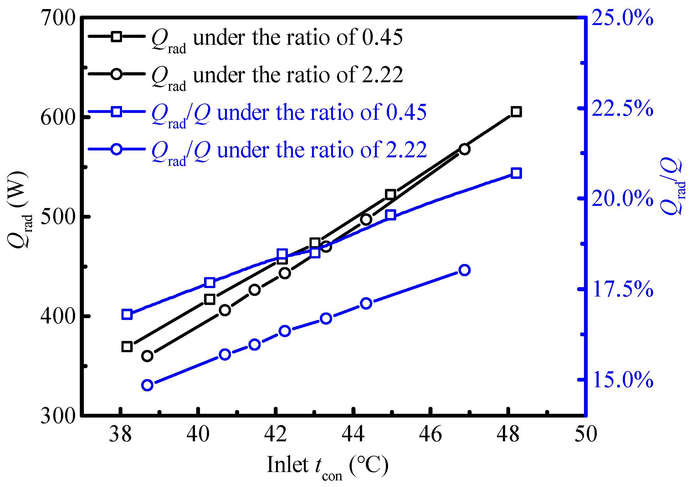
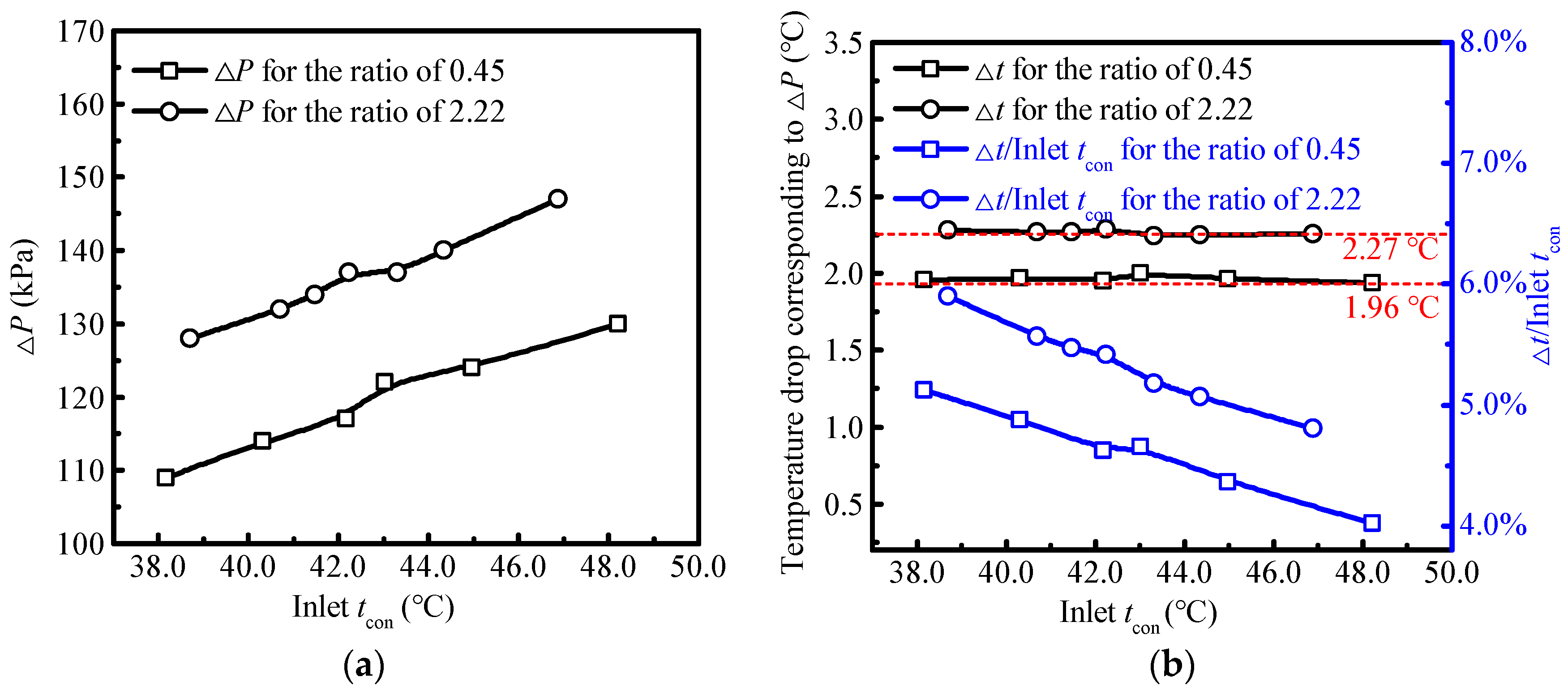
4.2.2. Comparison of the Proposed Heating Panels with Two Aspect Ratios
4.3. System Efficiency Investigations of the Proposed Heating Panels
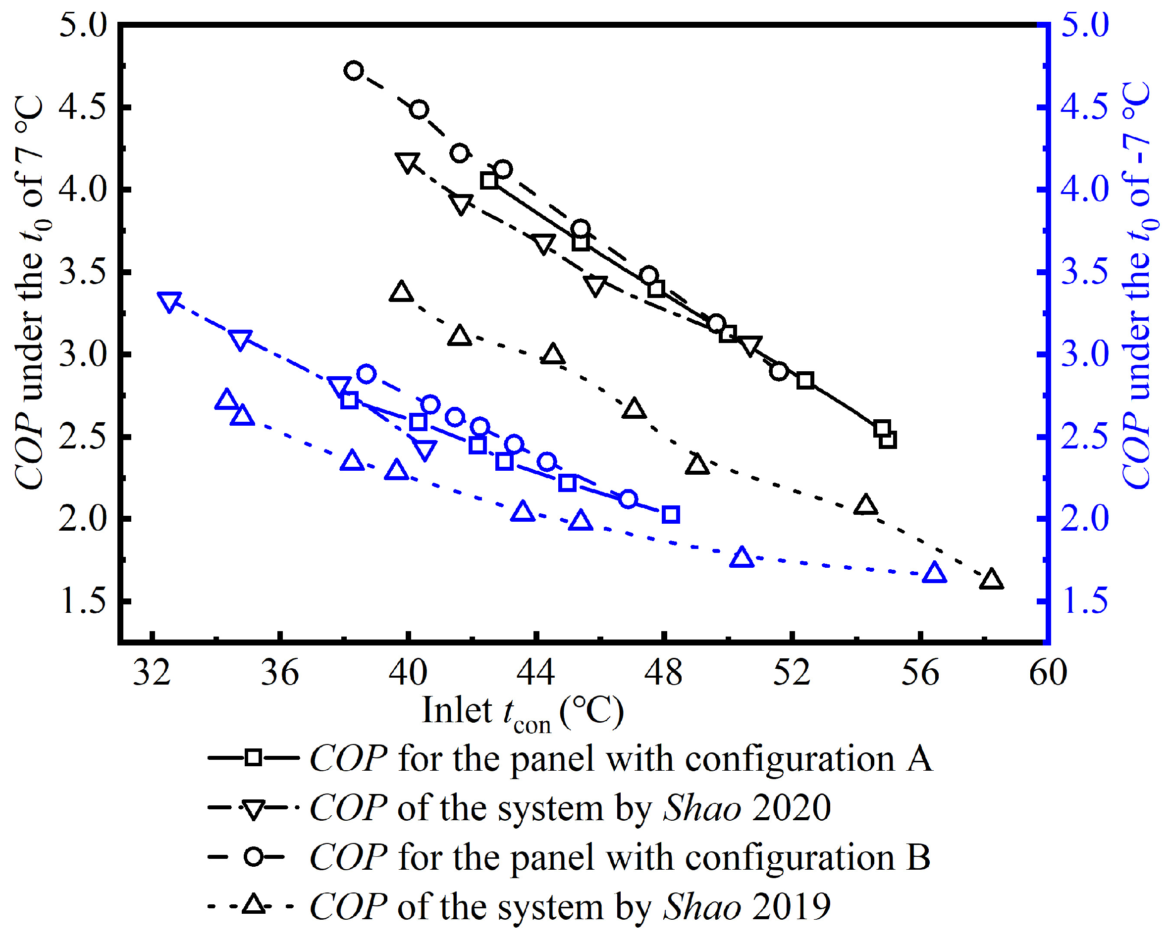
4.3.1. System COP Comparisons with Previous Heating Terminals
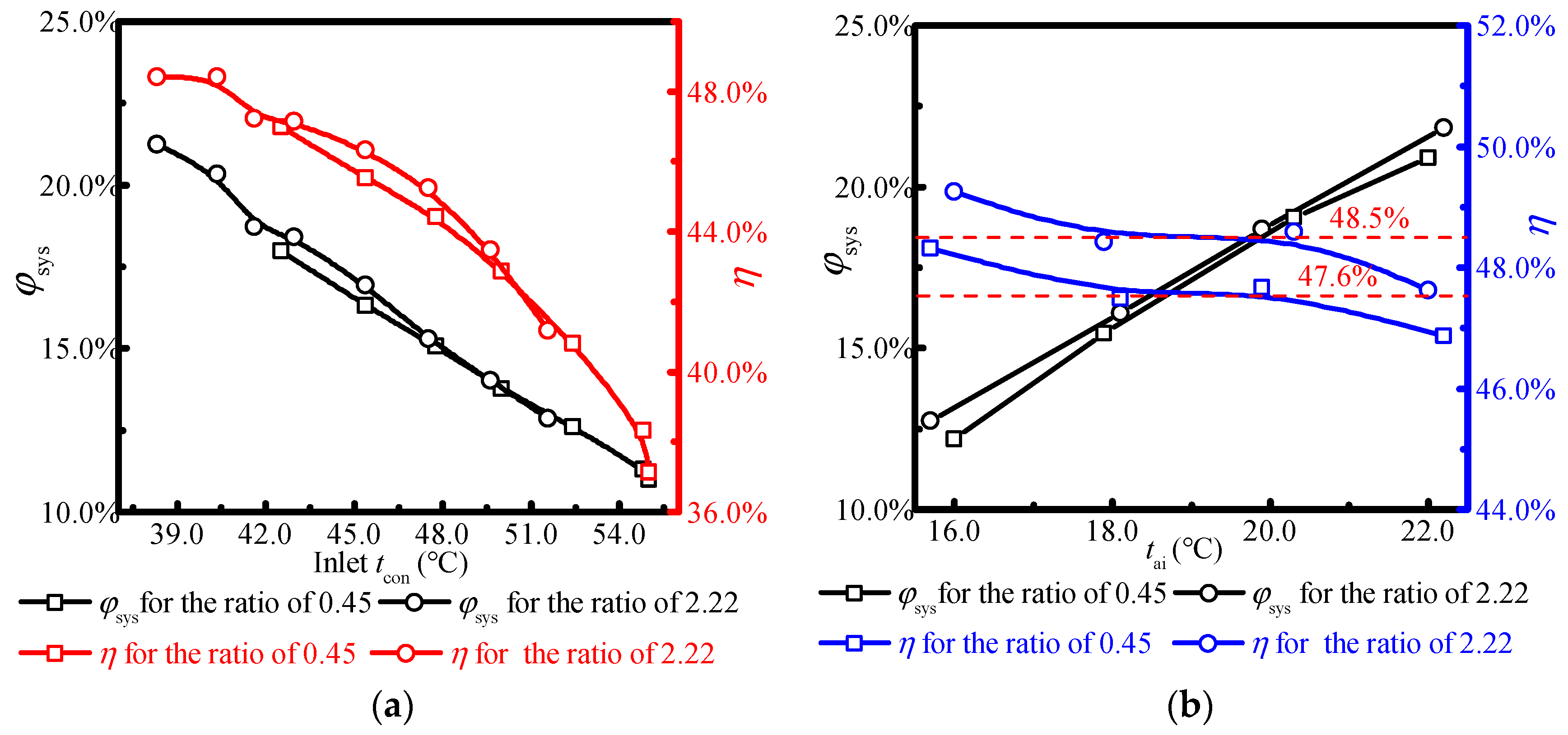
4.3.2. System Exergy Efficiencies of the Proposed Heating Panels with Two Aspect Ratios
5. Conclusions
- The proposed novel panel is competitive in indoor thermal comfort, thermal economy performance, and system efficiencies. The indoor temperature growth rate provided by the proposed heating panels is 15.2% lower than that of a previous heating terminal. The average heating capacity per cost is 5.4 W/USD, which is 24.1%~46.3% higher than that of previous panels. The system COP of the proposed heating panel is 0.04 to 0.73 higher than that of other direct-condensation heating terminals under the same heating conditions.
- The proposed heating panel with an aspect ratio of 0.45 provides a more comfortable indoor thermal environment than that with an aspect ratio of 2.22, while the panel with a high ratio creates a warmer local environment.
- Although the panel with a low aspect ratio is more prominent in reducing flow losses, the thermal economic performance and system efficiency of the proposed heating panel with an aspect ratio of 2.22 are more competitive than that with an aspect ratio of 0.45. The annual running cost for the panel with a ratio of 0.45 is 4.7% higher than that with a ratio of 2.22. Meanwhile, the average system η for the panel with a ratio of 2.22 is 48.5%, which is 0.9% higher than that with a ratio of 0.45.
Author Contributions
Funding
Data Availability Statement
Acknowledgments
Conflicts of Interest
Nomenclature
| A | Area (m2) |
| C | Cost (USD) |
| CADD | System additional costs (USD) |
| Cc | Convection heat transfer between human body and indoor air (W∙m−2) |
| CCER | System cost-effectiveness ratio (USD∙kWh−1) |
| CICC | Initial capital cost (USD) |
| CSYS | System investment cost (USD) |
| CWs | System energy prices corresponding to energy consumption (USD) |
| E | Evaporation heat of the human body (W∙m−2) |
| Edif | Skin diffusion evaporation loss (W∙m−2) |
| Ex | Rate of exergy (kW) |
| f | Coefficient |
| G | Refrigerant flow rate (kg∙s−1) |
| h | Specific enthalpy (kJ∙kg−1) |
| I | Proportion of evaluation indicators |
| M | Metabolic rate (W∙m−2) |
| P | Pressure (Bar) |
| Pai | Water vapor pressure (Pa) |
| Q | Heating capacity (W) |
| q | Heat flux (W) |
| R | Radiation heat transfer between human body and indoor chamber (W∙m−2) |
| s | Specific entropy (kJ∙kg−1∙°C−1) |
| T | Temperature (°C) |
| Ws | system input power (W) |
| Greek symbols | |
| Δ | Variation |
| α | Heat transfer coefficient (W∙m−2∙K−1) |
| γ | Uncertainties (%) |
| ε | Radiant surface emissivity |
| η | Task efficiency (%) |
| σ | Stephen Boltzmann constant, 5.67 × 10⁻⁸ W∙m−2∙K−4 |
| φ | Exergy efficiency (%) |
| χ | Wetted perimeter (mm) |
| Subscript | |
| 0 | Dead state |
| AUST | Comprehensive temperature of the building envelope |
| ai | air |
| cl | Clothing |
| con | Condenser |
| com | Compressor |
| d | Direct measurements |
| des | Destruction |
| eva | Evaporator |
| EEV | Electronic expansion valve |
| in | Inlet |
| ind | Indirect measurements |
| ins | Instruments |
| nc | Natural convection |
| oc | Occupying construction area |
| out | Outlet |
| pip | pipeline |
| pr | Production |
| ra | Random |
| rad | Radiation |
| rev | Reversed Carnot cycle |
| s | Surface |
| Acronyms | |
| ASHP | Air source heat pump |
| HVAC | Heating, ventilation, and air conditioning |
| COP | System coefficient of performance |
| PD2 | Percentage dissatisfied caused by vertical temperature difference |
| PD3 | Percentage dissatisfied caused by floor temperature |
| PMV | Predicted mean vote |
| PPD | Predicted percentage of dissatisfied |
| RH | Relative humidity |
References
- Chen, L.; Zhao, Y.; Xie, R.; Su, B.; Liu, Y.; Renfei, X. Embodied energy intensity of global high energy consumption industries: A case study of the construction industry. Energy 2023, 277, 127628. [Google Scholar] [CrossRef]
- Yildiz, O.; Yilmaz, M.; Celik, A. Reduction of energy consumption and CO2 emissions of HVAC system in airport terminal buildings. J. Affect. Disord. 2022, 208, 108632. [Google Scholar] [CrossRef]
- Lin, B.; Wang, Z.; Sun, H.; Zhu, Y.; Ouyang, Q. Evaluation and comparison of thermal comfort of convective and radiant heating terminals in office buildings. J. Affect. Disord. 2016, 106, 91–102. [Google Scholar] [CrossRef]
- Gendelis, S.; Jakovičs, A.; Ratnieks, J. Thermal comfort condition assessment in test buildings with different heating/cooling systems and wall envelopes. Energy Procedia 2017, 132, 153–158. [Google Scholar] [CrossRef]
- ANSI/ASHRAE Standard 55-2023; ANSI/ASHRAE Standard, Thermal Environmental Conditions for Human Occupancy. American Society of Heating, Refrigerating and Air-Conditioning Engineers: Atlanta, GA, USA, 2023.
- Huang, Y.; Situ, S.; Chen, X. Experimental Study on Optimal Air Temperature for Wall-Mounted Air Conditioning Heating Comfort. Environ. Technol. 2019, 37, 64–69. [Google Scholar]
- Wang, Y.; Zhang, X.; Ji, J.; Tian, Z.; Li, Y. Numerical Simulation of Thermal Performance of Indoor Airflow in Heating Room. Energy Procedia 2019, 158, 3277–3283. [Google Scholar] [CrossRef]
- Zhang, H.; Jiang, L.; Zheng, W.; You, S.; Jiang, T.; Shao, S.; Zhu, X. Experimental study on a novel thermal storage refrigerant-heated radiator coupled with air source heat pump heating system. J. Affect. Disord. 2019, 164, 106341. [Google Scholar] [CrossRef]
- Zhang, H.; Tao, M.; Jiang, T.; Zheng, W. Investigation of thermal comfort performance and optimization of a novel refrigerant-heated radiator. Indoor Built Environ. 2022, 31, 1540–1556. [Google Scholar] [CrossRef]
- Xu, S.; Ding, R.; Niu, J.; Ma, G. Investigation of air-source heat pump using heat pipes as heat radiator. Int. J. Refrig. 2018, 90, 91–98. [Google Scholar] [CrossRef]
- Zheng, C.; You, S.; Zhang, H.; Liu, Z.; Zheng, W.; Wu, Z.; Fan, M. Defrosting Performance Improvement of Air-Source Heat Pump Combined Refrigerant Direct-Condensation Radiant Floor Heating System with Phase Change Material. Energies 2020, 13, 4594. [Google Scholar] [CrossRef]
- Jiang, T.; Zheng, C.; You, S.; Zhang, H.; Wu, Z.; Wang, Y.; Wei, S. Experimental and numerical study on the heat transfer performance of the radiant floor heating condenser with composite phase change material. Appl. Therm. Eng. 2022, 213, 118749. [Google Scholar] [CrossRef]
- Shao, S.; Zhang, H.; You, S.; Wang, Y.; Li, Y. Prediction of thermal potentials of multi-panel refrigerant heated radiator based on a mathematical model considering refrigerant flow distribution. Energy Build. 2020, 228, 110446. [Google Scholar] [CrossRef]
- Shao, S.; Zhang, H.; You, S.; Zheng, W.; Jiang, L. Thermal performance analysis of a new refrigerant-heated radiator coupled with air-source heat pump heating system. Appl. Energy 2019, 247, 78–88. [Google Scholar] [CrossRef]
- Ghaleb, A.M.; Kaid, H.; Alsamhan, A.; Mian, S.H.; Hidri, L. Assessment and Comparison of Various MCDM Approaches in the Selection of Manufacturing Process. Adv. Mater. Sci. Eng. 2020, 2020, 4039253. [Google Scholar] [CrossRef]
- Mishra, N.K.; Adnan; Sohail, M.U.; Bani-Fwaz, M.Z.; Hassan, A.M. Thermal analysis of radiated (aluminum oxide)/water through a magnet based geometry subject to Cattaneo-Christov and Corcione’s Models. Case Stud. Therm. Eng. 2023, 49, 103390. [Google Scholar] [CrossRef]
- Ordu, M.; Der, O. Polymeric Materials Selection for Flexible Pulsating Heat Pipe Manufacturing Using a Comparative Hybrid MCDM Approach. Polymers 2023, 15, 2933. [Google Scholar] [CrossRef]
- Aich, W.; Adnan; Abbas, W.; Riaz, M.B.; Ahmed, M.; Ben Said, L.; Khan, S.U. Impacts of nanoscaled metallic particles on the dynamics of ternary Newtonian nanofluid laminar flow through convectively heated and radiated surface. Case Stud. Therm. Eng. 2024, 53, 103969. [Google Scholar] [CrossRef]
- AlBaidani, M.M.; Mishra, N.K.; Ahmad, Z.; Eldin, S.M.; Haq, E.U. Numerical study of thermal enhancement in ZnO-SAE50 nanolubricant over a spherical magnetized surface influenced by Newtonian heating and thermal radiation. Case Stud. Therm. Eng. 2023, 45, 102917. [Google Scholar] [CrossRef]
- Wang, Z.; Song, M.; Wang, F.; Ma, Z.; Lin, Q. Experimental investigation and seasonal performance assessment of a frost-free ASHP system with radiant floor heating. Energy Build. 2018, 179, 200–212. [Google Scholar] [CrossRef]
- Dincer, I.; Cengel, Y.A. Energy, Entropy and Exergy Concepts and Their Roles in Thermal Engineering. Entropy 2001, 3, 116–149. [Google Scholar] [CrossRef]
- Agberegha, L.O.; Aigba, P.A.; Nwigbo, S.C.; Onoroh, F.; Samuel, O.D.; Bako, T.; Der, O.; Ercetin, A.; Sener, R. Investigation of a Hybridized Cascade Trigeneration Cycle Combined with a District Heating and Air Conditioning System Using Vapour Absorption Refrigeration Cooling: Energy and Exergy Assessments. Energies 2024, 17, 1295. [Google Scholar] [CrossRef]
- GB/T 13754-2017; Test Methods of Thermal Output of Heating of Heating Radiators. Ministry of Housing and Urban Rural Development of the People’s Republic of China: Beijing, China, 2018.
- GB/T 7725-2022; Room Air Conditioners. State Administration for Market Regulation, Standardization Administration of the People’s Republic of China: Beijing, China, 2023.
- Dikici, A.; Akbulut, A. Performance characteristics and energy–exergy analysis of solar-assisted heat pump system. J. Affect. Disord. 2008, 43, 1961–1972. [Google Scholar] [CrossRef]
- JJF1059.1-2012; Evaluation and Expression of Uncertainty in Measurement. General Administration of Quality Supervision, Inspection and Quarantine of the People’s Republic of China: Beijing, China, 2012.
- Fanger, P.O.; Thomsen, J.O.B.; Højbjerre, J. Thermal comfort conditions in the morning and in the evening. Int. J. Biometeorol. 1974, 18, 16–22. [Google Scholar] [CrossRef] [PubMed]
- John, H.; Lienhard, I.V.; John, H.; Lienhard, V. A Heat Transfer Textbook, 4th ed.; McGraw-Hill: New York, NY, USA, 2018; Volume 6. [Google Scholar]
- BS EN ISO 7730; Ergonomics of the Thermal Environment-Analytical Determination and Interpretation of Thermal Comfort Using Calculation of the PMV and PPD Indices and Local Thermal Comfort Criteria. International Organization for Standardization: Geneva, Switzerland, 2005.
- Wu, Y.; Sun, H.; Duan, M.; Lin, B.; Zhao, H.; Liu, C. Novel Radiation-Adjustable Heating Terminal Based on Flat Heat Pipe Combined with Air Source Heat Pump. Engineering 2023, 20, 192–207. [Google Scholar] [CrossRef]
- Li, X.; Zhang, Y.; Fang, L.; Jin, Z.; Zhang, Y.; Yu, X.; Ma, X.; Deng, N.; Wu, Z. Energy, exergy, economic, and environmental analysis of an integrated system of high-temperature heat pump and gas separation unit. Energy Convers. Manag. 2019, 198, 111911. [Google Scholar] [CrossRef]
- Cengel, Y.A.; Boles, M.A. Thermodynamics: An Engineering Approach, 5th ed.; McGraw-Hill: New York, NY, USA, 2006. [Google Scholar]
- Suleman, F.; Dincer, I.; Agelin-Chaab, M. Energy and exergy analyses of an integrated solar heat pump system. Appl. Therm. Eng. 2014, 73, 559–566. [Google Scholar] [CrossRef]
- Shao, S.; Zhang, H.; Fan, X.; You, S.; Wang, Y.; Wei, S. Thermodynamic and economic analysis of the air source heat pump system with direct-condensation radiant heating panel. Energy 2021, 225, 120195. [Google Scholar] [CrossRef]


| Components of the ASHP Unit | Parameters |
|---|---|
| Evaporator | Size: 0.72 m × 0.48 m × 0.23 m (L × H × W) Refrigerant: R410A Outdoor Fan: speed range of 0~900 r/s |
| Electronic expansion valve | Opening degree: 0~100% stepless regulation |
| Compressor | Displacement: 10.2 cm3/rev Frequency: 0~100 Hz |
| Gas liquid separator | Type: LG-GST102MAA |
| Reversing valve | Type: SHF-50-79(P) |
| Sight glass | Type: DanFoss SGH6 014-1660 |
| Flowmeter | Type: DMF-1 mass flowmeter, Range: 0~100 kg/h. |
| Type | Channel Version (A × χ) | Copper Tube Layout Style | Fins Layout Style | Universal Fixed Dimensions | ||
|---|---|---|---|---|---|---|
| Developed panel | Ratio of 0.45 | Information | Isosceles trapezoidal (128 mm2 × 52 mm) | Interval piping | Wire welding | 1. Diameter of copper tube: φ 6.35 × 0.5 mm 2. Composite fin size: 3 cm × 1 cm (Length × Span) |
| Profile diagram | 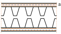 |  | ||||
| Ratio of 2.22 | Profile diagram | 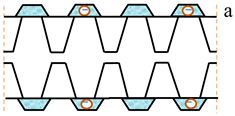 | 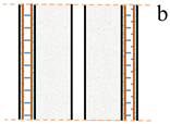 | |||
| Previously proposed panel | Type A [13] | Information | Hexagonal (128 mm2 × 48.8 mm) | Full channel piping | Wire welding | |
| Profile diagram | 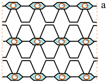 |  | ||||
| Type B [14] | Information | Hexagonal (128 mm2 × 48.8 mm) | Full channel piping | Spot welding | ||
| Profile diagram |  | 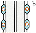 | ||||
| Parameters | Instrument Precision | Experimental Value Range | Error Range |
|---|---|---|---|
| T | ±0.5 °C | 12 °C~80 °C | ±0.63%~4.16% |
| P | 0.1% FS | 4.0 bar~29.0 bar | ±0.10% |
| RH | ± 1% | 20%~60% | ±1.67%~5% |
| G | ±0.002 kg/h | 49 kg/h~83 kg/h | ±0.0025%~0.004% |
| Ws | ±0.01 k W | 0.5 k W~1.4 k W | ±0.71%~2.00% |
| Q | - | 2.3 kW~3.5 kW | ±0.64%~4.16% |
| COP | - | 2.0~4.8 | ±0.96%~4.62% |
| Index | Position | Ratio | Range (%) | Proportions of Thermal Categories | ||
|---|---|---|---|---|---|---|
| A | B | C | ||||
| PPD | H: 0.1 m~2 m | 0.45 | 5.0~29.5 | 25% | 35% | 35% |
| 2.22 | 5.0~28.3 | 35% | 20% | 30% | ||
| PD2 | H: 0.1 m~2 m | 0.45 | 1.3~5.0 | 80% | 20% | 0 |
| 2.22 | 2.8~20.6 | 20% | 40% | 20% | ||
| PD3 | - | 0.45 | 9.9 | 100% | - | - |
| 2.22 | 9.6 | 100% | - | - | ||
| Type | Csys | CADD | CICC | ||||
|---|---|---|---|---|---|---|---|
| Components | Heat Pump Unit | Copper Tube | Steel Panel a | Fin b | |||
| Unit Price | 288.5 USD/Unit | 1.44 USD/m | 3.60 USD/m2 | 2.16 USD/m | |||
| System with novel heating panels | Parameters | 1 unit | 50 m | 4 × 2 × 0.9 m2 | 2 × 60 × 0.07 × 0.72 m2 | 15% CICC | Csys + CADD |
| Total price | 399.5 USD | 70.5 USD | 470.0 USD | ||||
| System with the previous heating terminal in ref. [13] | Parameters | 1 unit | 117 m | 6 × 1.6 × 0.9 m2 | 144 × 0.07 × 0.72 m2 | 15% CICC | Csys + CADD |
| Total price | 503.8 USD | 88.9 USD | 592.7 USD | ||||
| System with the previous heating terminal in ref. [14] | Parameters | 1 unit | 40 m | 4 × 0.9 × 1.6 m2 | 50 × 0.07 × 1.4 m2 | 15% CICC | Csys + CADD |
| Total price | 370.5 USD | 65.4 USD | 435.9 USD | ||||
| Panel Type | Number | Fluid | Position | State | Flow Rate m (kg/s) | Temperature (°C) | Pressure (kPa) | Specific Enthalpy (kJ/kg) | Specific Entropy (kJ/kg k) | Exergy Rate (kW) |
|---|---|---|---|---|---|---|---|---|---|---|
| 0 | R410A | - | Dead state | - | 7 | 101.3 | 455.16 | 2.12 | ||
| Ratio of 0.45 | 1 | Evaporator outlet | Vapor | 0.01773 | 5.30 | 922.3 | 423.44 | 1.80 | 1.18 | |
| 1′ | Compressor inlet | Vapor | 0.01773 | 9.20 | 922.3 | 427.88 | 1.82 | 1.18 | ||
| 2 | Compressor outlet | Vapor | 0.01773 | 58.70 | 2751.3 | 446.56 | 1.78 | 1.68 | ||
| 2′ | Panel inlet | Vapor | 0.01773 | 52.00 | 2751.3 | 436.02 | 1.75 | 1.66 | ||
| 3 | Panel outlet | Liquid | 0.01773 | 43.10 | 2630.3 | 272.15 | 1.24 | 1.30 | ||
| 3′ | EEV inlet | Liquid | 0.01773 | 41.40 | 2630.3 | 268.78 | 1.23 | 1.30 | ||
| 4 | EEV outlet/ Evaporator inlet | Mixture | 0.01773 | 5.72 | 957.3 | 268.78 | 1.25 | 1.20 | ||
| Ratio of 2.22 | 1 | R410A | Evaporator outlet | Vapor | 0.01764 | 4.70 | 917.3 | 422.89 | 1.80 | 1.17 |
| 1′ | Compressor inlet | Vapor | 0.01764 | 8.60 | 917.3 | 427.35 | 1.82 | 1.17 | ||
| 2 | Compressor outlet | Vapor | 0.01764 | 58.90 | 2751.3 | 446.86 | 1.79 | 1.68 | ||
| 2′ | Panel inlet | Vapor | 0.01764 | 52.30 | 2751.3 | 436.52 | 1.75 | 1.65 | ||
| 3 | Panel outlet | Liquid | 0.01764 | 42.10 | 2606.3 | 270.19 | 1.23 | 1.29 | ||
| 3′ | EEV inlet | Liquid | 0.01764 | 40.30 | 2606.3 | 266.67 | 1.22 | 1.28 | ||
| 4 | EEV outlet/ Evaporator inlet | Mixture | 0.01764 | 5.99 | 965.3 | 266.67 | 1.24 | 1.20 |
| Panel Type | Component | Exin [W] | Exout [W] | Exdest [W] |
|---|---|---|---|---|
| Ratio of 0.45 | Evaporator | 1204.5 | 1175.1 | 29.4 |
| Compressor | 1965.2 | 1683.3 | 281.9 | |
| Condenser (heating panel) | 1655.8 | 1431.3 | 224.5 | |
| Expansion valve | 1295.7 | 1204.5 | 91.3 | |
| Pipeline | 1683.3 | 1655.8 | 27.5 | |
| System | 7804.5 | 7150.0 | 654.5 | |
| Ratio of 2.22 | Evaporator | 1199.5 | 1166.6 | 32.9 |
| Compressor | 1946.5 | 1675.4 | 271.1 | |
| Condenser (heating panel) | 1648.5 | 1423.4 | 225.1 | |
| Expansion valve | 1284.7 | 1199.5 | 85.1 | |
| Pipeline | 1675.4 | 1648.5 | 26.9 | |
| System | 7754.6 | 7113.5 | 641.1 |
Disclaimer/Publisher’s Note: The statements, opinions and data contained in all publications are solely those of the individual author(s) and contributor(s) and not of MDPI and/or the editor(s). MDPI and/or the editor(s) disclaim responsibility for any injury to people or property resulting from any ideas, methods, instructions or products referred to in the content. |
© 2024 by the authors. Licensee MDPI, Basel, Switzerland. This article is an open access article distributed under the terms and conditions of the Creative Commons Attribution (CC BY) license (https://creativecommons.org/licenses/by/4.0/).
Share and Cite
Shao, S.; Xu, C. Performance Analysis of Novel Direct-Condensation Heating Panels Integrated with Air Source Heat Pump System on Thermal Economy and System Efficiencies. Energies 2024, 17, 4561. https://doi.org/10.3390/en17184561
Shao S, Xu C. Performance Analysis of Novel Direct-Condensation Heating Panels Integrated with Air Source Heat Pump System on Thermal Economy and System Efficiencies. Energies. 2024; 17(18):4561. https://doi.org/10.3390/en17184561
Chicago/Turabian StyleShao, Suola, and Chengcheng Xu. 2024. "Performance Analysis of Novel Direct-Condensation Heating Panels Integrated with Air Source Heat Pump System on Thermal Economy and System Efficiencies" Energies 17, no. 18: 4561. https://doi.org/10.3390/en17184561
APA StyleShao, S., & Xu, C. (2024). Performance Analysis of Novel Direct-Condensation Heating Panels Integrated with Air Source Heat Pump System on Thermal Economy and System Efficiencies. Energies, 17(18), 4561. https://doi.org/10.3390/en17184561