Article

A Power-RPM Reduced-Order Model and Power Control Strategy of the Dual Three-Phase Permanent Magnet Synchronous Motor in a V/f Framework for Oscillation Suppression

by
Riqing Su
1,
Yuanze Wang
1,
Hui Deng
1,
Xiong Liu
1,* and
Yuanpeng Guan
2,*
1
Energy Electricity Research Center, Jinan University, Zhuhai 519070, China
2
School of Automation, Guangdong University of Technology, Guangzhou 510006, China
*
Authors to whom correspondence should be addressed.
Energies 2024, 17(18), 4563; https://doi.org/10.3390/en17184563
Submission received: 27 July 2024 / Revised: 2 September 2024 / Accepted: 9 September 2024 / Published: 12 September 2024

Abstract

:
The dual three-phase permanent magnet synchronous motor (DTP-PMSM) under a V/f control framework is widely applied in belts, fans, pumps, etc. However, the oscillation in power and rotor speed is difficult to quantify and suppress, due to the higher-order model of the DTP-PMSM. Thus, a power-revolutions per minute (RPM) reduced-order model and power control strategy of the DTP–PMSM are proposed for oscillation description and suppression. Firstly, according to the structure and V/f control framework, the reduced-order model is proposed under a power-RPM scale with coupled performances between sub-PMSMs, and then the decoupled method is employed. Moreover, the oscillated performances of power and rotor speed are detailed in small signals. Secondly, a power control strategy is proposed, including active power feedforward for active damping and reactive power droop control for high power quality and approaching optimal torque per ampere. Compared with the traditional strategies, the proposed method can achieve a stable and efficient operation, with a higher power factor of the DTP–PMSM, less stator current, and lower electromechanical power loss. Finally, an experimental platform of the DTP–PMSM is set up for the correctness and superiority of the proposed method.

1. Introduction

Recently, there has been a significant research interest regarding the control of dual three-phase permanent magnet synchronous motors (DTP-PMSMs) due to their appealing features such as high power density, high efficiency, and robust rotor structure [1,2]. When the DTP–PMSMs are used in applications such as pumps and fans that do not require high dynamic performance, V/f control is very suitable [3]. Flux-oriented control (FOC) [4] and direct torque control (DTC) [5] require the encoder to provide precise rotor angles. However, the addition of encoders not only increases the cost of the driving device but also greatly increases the control wiring and interface circuits between the motor and the control system, making the system susceptible to environmental interference and reducing reliability. Furthermore, the sensorless algorithm based on FOC and DTC does not require an encoder but requires precise acquisition of the motor’s currents and voltages, and this inevitably increases the complexity of the control algorithm. Compared with FOC and DTC, the V/f control strategy is an open-loop sensorless control method to approximate the flux linkage as the rated value without any motor parameter; thus, it has the salient advantages of simplicity and reliability, which have attracted the attention of many researchers. However, the sneak oscillation in rotor speed and power would occur under a V/f control framework due to the interaction instability between the DTP–PMSM and its inverter [6]. Therefore, it is essential for oscillation analysis and suppression to optimize efficient operations of the DTP–PMSM.
For oscillation analysis of a DTP–PMSM, the model is fundamental. In three-phase PMSM under the V/f control framework, a full-order small-signal model is established and detailed for the impact of parameters such as speed, stator resistance, stator inductance, excitation flux, moment of inertia, and load on stability [6,7,8]. Furthermore, in literature [9], the effect of dead time of inverter is discussed on the power quality and stability of the PMSM, based on the volt-second balance principle. Moreover, based on the stator voltage and stator flux equations, the DTP–PMSM is modeled with higher orders with more coupling windings and a more complex structure [10]. However, the model of DTP–PMSM or PMSM in the V/f control framework is high order; thus, the accurate oscillation analysis and quantification of power and rotor speed are the challenges.
For the oscillation suppression and stability of power and rotor speed of the PMSM under the V/f control framework, the strategies mainly include active power feedback [8,11,12], current feedback [13,14,15,16,17], and virtual inertia control [18,19]. The literature [8] presents a power feedback loop into speed control loop for the PMSM under the V/f control framework to suppress speed oscillations. However, the speed oscillation is hard to analyze exactly under the full-order model of the PMSM, causing a hard-to-design feedback parameter and unquantifiable damping ratio. Moreover, voltage vectors are calculated complicatedly and rely on accurate real-time motor parameters. In literature [11], an active power feedback loop is inserted into the speed control loop to avoid out-of-step. However, in previous works, voltage compensation was lacking, and stator voltages of the PMSM performed with poor dynamic behavior, leading to the inferior dynamic response of the PMSM. Furthermore, in the literature [13,14,15,16,17], the current feedback loop is inserted into the speed control loop to suppress the oscillation of rotor speed indirectly and optimize operation current for high efficiency, because stator current indirectly implies the torque ripple and rotor angle in the PMSM dq frame. However, the real-time accurate estimation of rotor angle is required, resulting in increased computational complexity and poor dynamic effects. It would weaken the advantages of the PMSM under V/f control. On the other hand, in the literature [18], a virtual inertia control is inducted into PMSM under the V/f control framework, in which an inverter is operated as a virtual synchronous machine to damp oscillation. However, the starting current of this structure may be too high. The literature [19] further introduces a virtual damping coefficient, which suppresses the vibration caused by excessive starting current and rotational speed. However, the active damping is based on the speed difference between the inverter and the PMSM under the time scale of power; thus, the sneak oscillation of current would be stimulated inexplicably, and the advantage of the V/f control framework being sensorless is destroyed and lost. Moreover, due to the similar structure, the oscillation of the DTP-PMSM under the V/f control framework would potentially occur, which is seldom discussed in previous works. The previous oscillation suppression strategies can also be employed in the DTP–PMSM. However, the accurate oscillation analysis and suppression of power and rotor speed are more urgent challenges, due to the more complex structure and more coupling windings.
Moreover, the previous power and rotor speed oscillation suppression methods are based on the active power feedback, neglecting the maximum torque per ampere (TPA) and current and reactive power quality of the DTP–PMSM, even if in the PMSM [20]. Moreover, the traditional maximum TPA and current quality methods [21,22] require real-time compensation of the rotor angle. However, it is not advantageous for the V/f control framework and power and rotor speed oscillation suppression methods with poor dynamic performance and power factor.
To solve the above-mentioned problems, a power-RPM reduced-order model and power control strategy of the PMSM under the V/f control framework are proposed for power and rotor speed oscillation suppression. Firstly, the structure and the V/f control framework are detailed, and the reduced-order model of the PMSM under the V/f control framework is proposed in a power-RPM scale. Then, the essential oscillation performances of power and rotor speed are performed theoretically. Secondly, a power control strategy is proposed, including active power feedforward for active damping and reactive power droop control for high power quality and to approach the optimal TPA. Moreover, a comparison between the proposed strategy and current feedback strategies is carried out; the DTP–PMSM achieves simplified model and analysis, stable and efficient operation with lower computation, higher power factor, approaching of the optimal TPA, less stator current, and lower electromechanical power loss. Finally, the DTP–PMSM under the V/f control framework is set to verify the proposed method.
The rest of this paper is organized as follows: Section 2 presents the reduced-order model of the DTP–PMSM under the V/f control framework and oscillation characteristics of power and rotor speed. In Section 3, a power control strategy is proposed, with active power feedforward for active damping and reactive power droop control for high power quality and approaching of the optimal TPA. In Section 4, experiments are set up for verification of the proposed reduced-order model and power control strategy. Finally, the conclusion is drawn.

2. Power-RPM Reduced-Order Model and Oscillation Analysis

2.1. Power-RPM Reduced-Order Model

The DTP–PMSM is driven by dual inverters, shown in Figure 1. The DTP–PMSM has two symmetric sets of windings, which are 30° phase shift (Δθ), marked as ABC and UVW in each winding. ia, ib, ic, iu, iv, iw are phase currents, Tl is the load torque, Te is the electromagnetic torque, Jm is the inertia, and ωe is the mechanical angular velocity. The stator voltage equation and stator flux equation for DTP–PMSM in the double dq frame are depicted as Equations (1) and (2) [23], where
u d 1 u q 1 u d 2 u q 2 = R 0 0 0 0 R 0 0 0 0 R 0 0 0 0 R i d 1 i q 1 i d 2 i q 2 + ψ ˙ d 1 ψ ˙ q 1 ψ ˙ d 2 ψ ˙ q 2 + ω m e 0 1 0 0 1 0 0 0 0 0 0 1 0 0 1 0 ψ d 1 ψ q 1 ψ d 2 ψ q 2
ψ d 1 ψ q 1 ψ d 2 ψ q 2 = L d 0 L d d 0 0 L q 0 L q q L d d 0 L d 0 0 L q q 0 L q i d 1 i q 1 i d 2 i q 2 + 1 0 1 0 ψ f
R is the stator resistance; ψf is the permanent magnet flux-linkage; ωme is the rotor electrical angular velocity; ud1, uq1, ud2, uq2, id1, iq1, id2, iq2 and ψd1, ψq1, ψd2, ψq2 are the dq-axes stator voltages, currents, and the permanent magnet flux-linkage of both windings, respectively; Ld and Lq are the dq-axes inductances for the first winding and second winding; and Ldd and Lqq are the dq-axes mutual inductances between the windings.
In Equation (2), the DTP–PMSM shows the coupling effect by the off-diagonal elements Ldd and Lqq. Thus, the decoupling method for the DTP–PMSM is achieved by voltage feedforward as,
U d 1 = L q q i q 2 ω e U q 1 = L d d i d 2 ω e U d 2 = L q q i q 1 ω e U q 2 = L d d i d 1 ω e
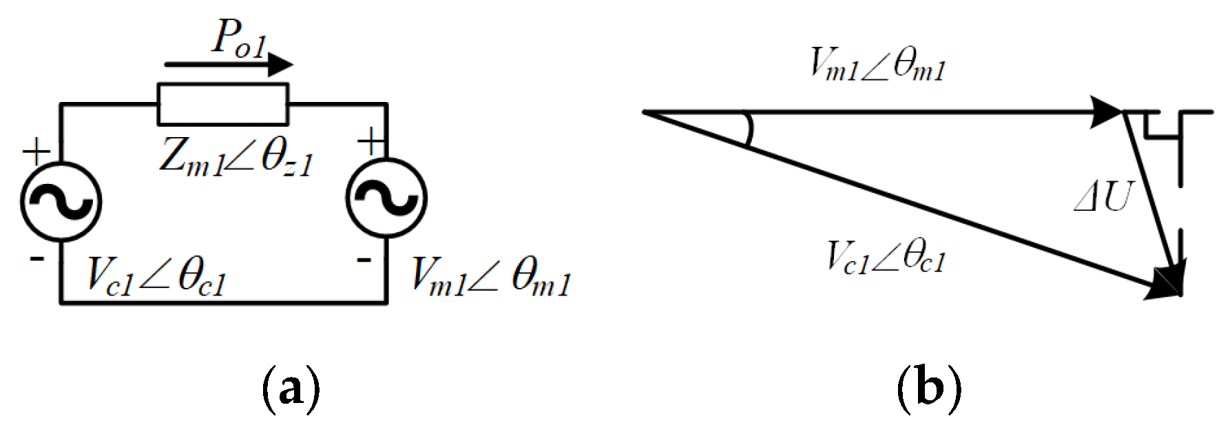
Thus, the DTP–PMSM can be equivalent to two independent PMSMs, and simplicity control is achieved. Taking the first winding as an example in Figure 2a. The voltage source Vmθm1 is the back EMF of first winding, Vc1θc1 is the equivalent voltage of inverter, and Zm1θz1 is the impedance parameter of the first winding. According to Figure 2b, the voltage vector difference, ΔU, is expressed as,
Δ U = V c 1 cos θ c 1 θ m 1 + j V c 1 sin θ c 1 θ m 1 V m 1
The current, I, is derived as,
I = Δ U Z m 1 = V c 1 cos θ c 1 θ m 1 + j V c 1 sin θ c 1 θ m 1 V m 1 Z m 1 cos θ z 1 + j Z m 1 sin θ z 1
Delivery power is as Equation (6).
S o 1 = P o 1 + j Q o 1 = V m 1 V c 1 cos θ c 1 θ m 1 + j V c 1 sin θ c 1 θ m 1 V m 1 Z m 1 cos θ z 1 + j Z m 1 sin θ z 1 ¯
From Equation (6), the active power of the inverter is derived as,
P o 1 = V c 1 V m 1 Z m 1 cos θ c 1 θ m 1 V m 1 2 Z m 1 cos θ z 1 + V c 1 V m 1 Z m 1 sin θ c 1 θ m 1 sin θ z 1
When the motor is running at a low speed, the resistance of the motor cannot be ignored. Therefore, by applying virtual negative impedance control [24], the stator resistance of the motor can be offset in the model. The voltage source on the converter side and the back electromotive force voltage source generated by the permanent magnet on the motor side are only connected through inductance. Therefore, sin(θz1) ≈ 1. Virtual negative impedance is easy to implement, which requires adding current to the controller output multiplied by resistance.
When the electrical frequency, ωme, of the motor is higher than 10 Rs/Lq at high speed, resistance can be ignored. Therefore, sin(θz1) ≈ 1.
Since the motor is operating at the rated power, the phase difference between the two voltage sources is small. Therefore, sin(θc1θm1) ≈ θc1θm1. Moreover, the dq-axis inductances of the interior PMSM are different, and voltage vectors of the inverter and PMSM are oriented around the q-axis. Hence, the motor impedance Zm1ωmeLq and Equation (5) can be simplified as,
P o 1 = V c 1 V m 1 Z m 1 θ c 1 θ m 1 = V c 1 V m 1 ω m e L q θ c 1 θ m 1
In addition, the mechanical dynamics of the first winding are governed by the following equation,
0.5 J m d ω m e d t = 0.5 T e 0.5 T l = 0.5 n 2 P o 1 ω m e 0.5 n T l
Combining the Equations (1), (6), and (7), the power-RPM reduced-order model is proposed as Equation (10), which is as follows:
ω ˙ m e P ˙ o 1 = 0 n 2 J m ω m e 3 φ f 2 ω c e 1 2 L q 0 × ω c e 1 ω m e P o 1 n T l J m 0
where ωce1 is the frequency of the first inverter, and n is the number of motor pole pairs. Similarly, the power-RPM reduced-order model in second winding is as follows:
ω ˙ m e P ˙ o 2 = 0 n 2 J m ω m e 3 φ f 2 ω c e 2 2 L q 0 × ω c e 2 ω m e P o 2 n T l J m 0
where ωce2 is the frequency of the second inverter.
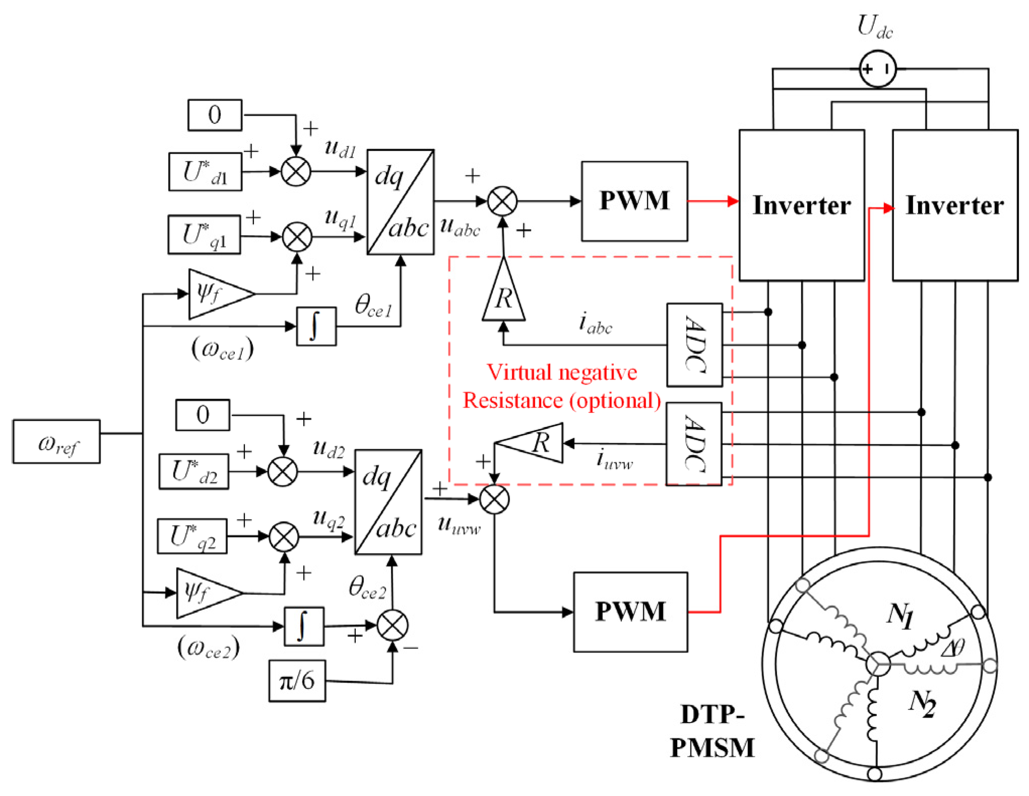
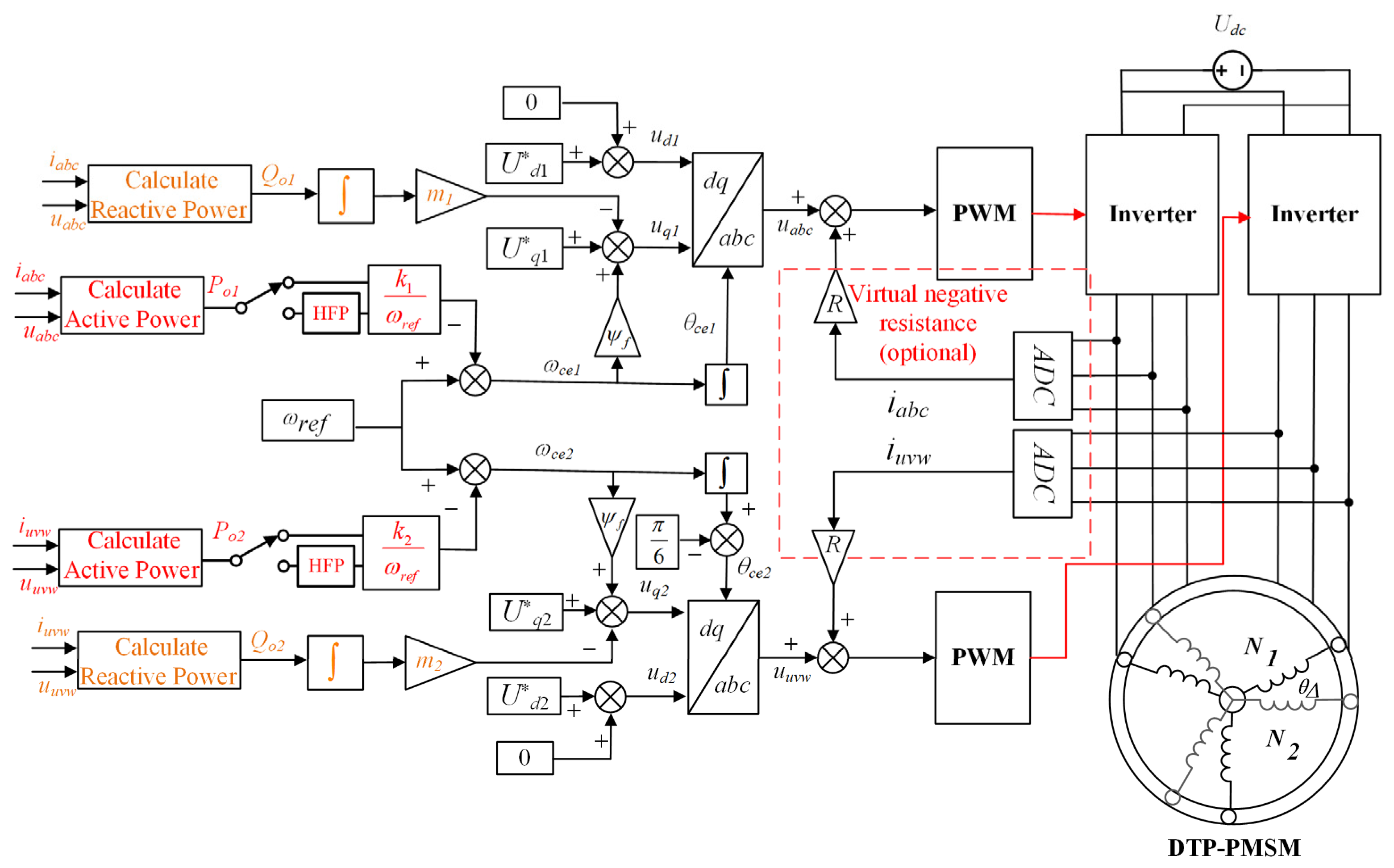
Thus, the DTP–PMSM under the V/f control framework is depicted in Figure 3. The d-axis voltage is set as zero for high voltage quality, and the q-axis voltage is obtained by the permanent magnet flux, ψf, and the electrical frequency, ωref, which is for speed regulation. The angles θc1 and θc2 are achieved by integrating ωrref for Park’s transformation. Moreover, the virtual negative resistance is optional on account of accelerating startup, due to the large resistance of PMSM at low speed.

2.2. Oscillation Analysis

Inserting small signals into Equation (8), the small-signal state Equation (12) is expressed as follows:
δ ω ˙ m e δ P ˙ o 1 = n 2 P o 1 0.5 J m ω m e 2 n 2 0.5 J m ω m e K p 1 ω c e 1 0 × δ ω m e δ P o 1 + 0 B 1 × δ ω c e 1
where K p 1 = 3 ψ f 2 / 2 L q , B 1 = 3 φ f 2 2 ω c e 1 ω m e / 2 L q .
Thus, the corresponding transfer function from δωce1 to δωme can be derived as follows:
δ ω m e s δ ω c e 1 s = n 2 J m 1 ω m e 1 B 1 s 2 + n 2 P o 1 J m ω m e 2 s + n 2 J m ω m e K p 1 ω c e 1
The oscillation frequency and damping ratio are as follows:
ω r e n K p 1 J m
ε n P o 1 2 ω m e 2 J m K p 1
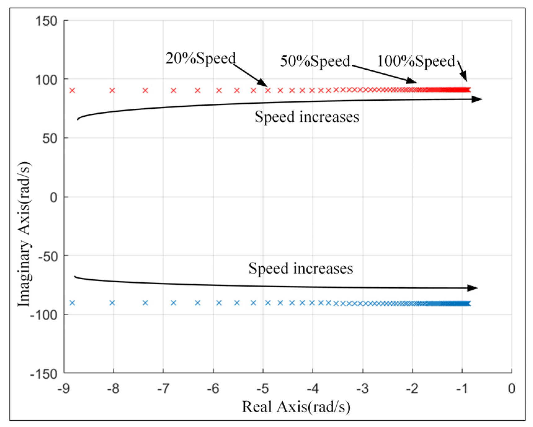
The pole locus of Equation (10) is shown in Figure 4. The pole locus will be closer to the imaginary axis as the speed increases from 0 to 100% under the rated power, which means that the damping of the system becomes smaller and smaller. Thus, the DTP–PMSM would be oscillated seriously with increasing speed. In fact, severe oscillation may cause the motor to fail to start or the load to suddenly change and become unstable during the steady state. Compared to traditional full-order models, the proposed power-RPM reduced-order model can not only quantify damping ratio and oscillation frequency but can also analyze the essence of oscillation.

3. Power Control Strategy

3.1. Active Power Feedback for Active Damping

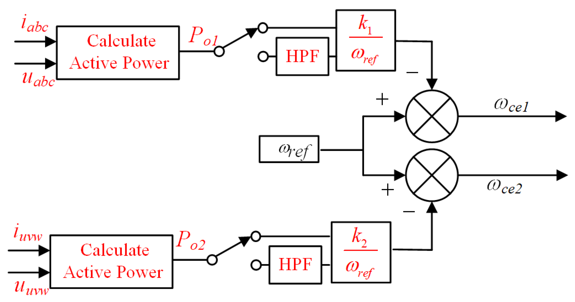
The amount of electrical frequency disturbance is proportional to the amount of power disturbance as shown in Equations (10) and (11). Therefore, it is reasonable to suppress speed oscillations by introducing active power. To improve the damping ratio and suppress oscillation, active power can be fed back into speed control loop, as in Figure 5. Furthermore, the active power can be selected to pass through a high-pass filter (HPF) with a low cutoff frequency to improve the steady-state tracking performance.
The Power-RPM reduced-order model with power feedback can be expressed as Equation (16) from Equation (10), which is as follows:
δ ω ˙ m e δ P ˙ o 1 = n 2 P o 1 J m ω m e 2 n 2 J m ω m e K p 1 ω r e f + k 1 P o 1 ω r e f K p 1 k 1 ω m e ω r e f 2 k 1 + 2 k 1 2 P o 1 ω r e f 2 × δ ω m e δ P o 1 + 0 B 1 × δ ω r e f
where k1 is active power feedback coefficient.
ωme is approximately equal to ωref, when DTP-PMSM is in steady-state operation. Thus, the corresponding transfer function from δωref and δωme can be derived as follows:
δ ω m e s δ ω r e f s = n 2 J m 1 ω m e 1 B s 2 + k 1 K p 1 + P o 1 n 2 J m 1 ω m e 2 2 k 1 2 K p 1 P o 1 ω m e 2 s + K p 1 n 2 J m 1 2 k 1 2 P o 1 2 ω m e 4
In Equation (15), when the motor operates at high speed,
1 2 k 1 2 P o 1 2 ω m e 4 and k 1 K p 1 P o 1 n 2 J m 1 ω m e 2 2 k 1 2 K p 1 P o 1 ω m e 2 . Therefore, Equation (16) can be obtained by simplifying Equation (15).
δ ω m e s δ ω r e f s = n 2 J m 1 ω m e 1 B 1 s 2 + k 1 K p 1 s + K p 1 n 2 J m
In Equation (16), the damping term k1Kp1 is determined by ψf and Lq, independent of speed and power. Thus, in order to maintain a constant damping ratio of 0.707, the coefficient k1 can be designed as follows:
k 1 = 2 n K p 1 J m
Similarly, the coefficient k2 in second winding can be designed as follows:
k 2 = 2 n K p 2 J m
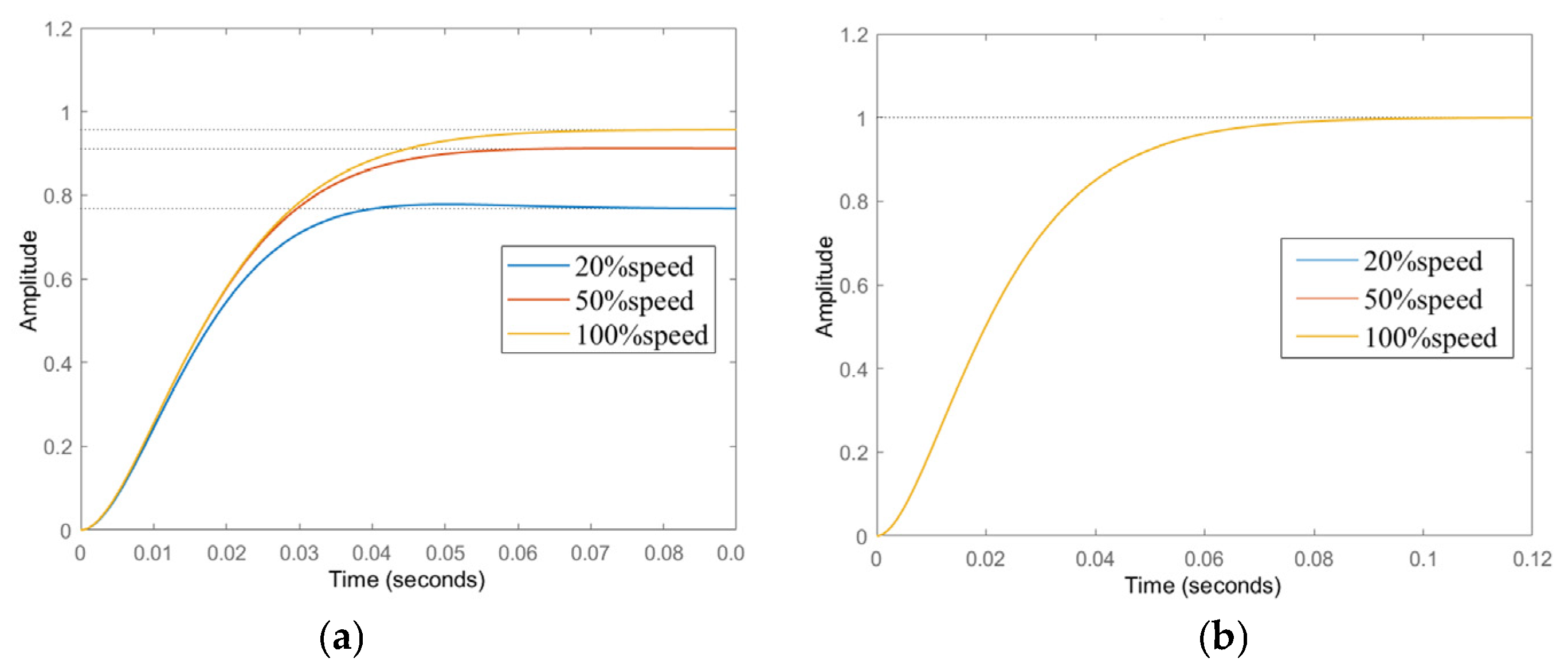
The step response of Equation (15) is as shown in Figure 6a. The steady-state deviation of speed always exists, whether it is 20% speed, 50% speed, or 100% speed. The introduced active power includes both DC and fluctuating components. The fluctuation part suppresses the oscillation, but the DC part will persist due to loading. Therefore, the rotational speed will decrease by a portion during the loading process. To eliminate the steady-state error in speed, active power is fed back through a 0.25 Hz first-order HPF. At this moment, Po1/Po2 in the Equation (15) is the fluctuating part, which is relatively small. Further illustrate the step response, as shown in the Figure 6b, with no steady-state error in velocity. HPF will not affect coefficient k1, k2 design and system stability, and can improve the tracking ability of speed.
In Figure 7, the DTP–PMSM under V/f control frame without active damping would be unstable, when the load is increased. The DTP–PMSM with current feedback scheme [17] shows an increased damping ratio in dominant poles, when the load is enlarged. However, it would be seriously affected by the closed non-dominant poles, thus, the effect of the current feedback coefficient is hardly designed and quantified. Compared with the current feedback scheme, the DTP–PMSM with proposed power feedback maintains a higher damping ratio, and the active power feedback coefficient can be designed and quantified under proposed power-RPM reduced-order model.

3.2. Reactive Power Droop Control for High Power Quality and Approaching of the Optimal TPA

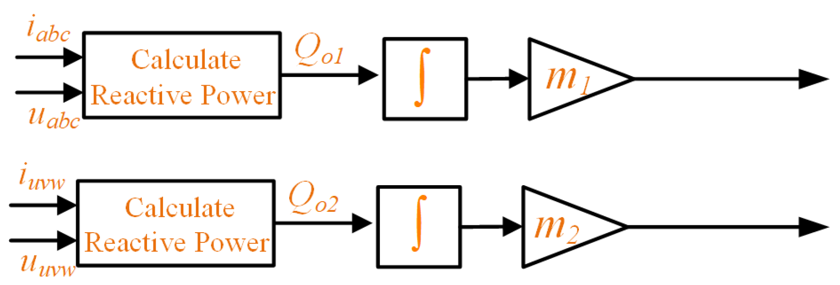
From the perspective of power, the quality and distribution of powers can be optimized to achieve high power factor, less stator current, and approach the optimal TPA of DTP–PMSM. Thus, the reactive power droop control is proposed to the V/f control framework. Taking sub-inverter 1 and sub-PMSM 1 as an example, according to Equations (4)–(6), the reactive power is derived as follows:
Q 01 V m 1 ( V m 1 V c 1 ) ω e L d
The reactive power is adjusted by voltage. The reactive power droop control is designed as Equation (20) in Figure 8
V c 1 = V c 1 m 1 Q 01 d t
where m1 is the reactive power droop coefficient, and Vc1* is the value of Vc1 at the previous moment. Taking the derivative of Equation (20), Equation (21) is obtained as follows:
V ˙ c 1 = m 1 Q o 1
Combining Equation (10) with Equation (21), the small-signal state equation is expressed as follows:
δ ω ˙ m e δ P ˙ o 1 δ V ˙ c 1 = n 2 P o 1 J m ω m e 2 n 2 J m ω m e 0 3 m 1 ψ f V c 1 2 L q 3 m 1 ψ f 2 L q V c 1 k 1 ω r e f 3 m 1 ψ f 2 L q ω r e f ω m e k 1 P o 1 ω r e f 3 m 1 ψ f 2 2 L d 0 3 m 1 ψ f 2 L d × δ ω m e δ P o 1 δ V c 1 + 0 3 m 1 ψ f V c 1 2 L q + k 1 P o 1 ω r e f 0 × δ ω r e f
Similarly, the sub-inverter 2 and sub-PMSM 2 can employ the same reactive power droop control strategy. By the control strategy, the reactive powers are distributed in self- adaptation between sub-PMSMs. Thus, the reactive powers of sub-PMSMs would be zero under stable operation. Namely, stator currents are reduced, to achieve a high power factor, and to indirectly approach optimal TPA.
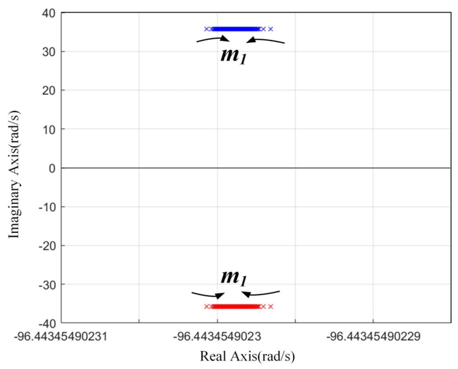
When m1 is increased, the pole locus of DTP–PMSM under rated torque load and rated speed is almost unchanged shown in Figure 9. Namely, m1 would almost certainly not impact the stability.
In the reactive power control strategy in theV/f control framework, the reactive power is distributed and injected into sub-PMSMs, to achieve a high power factor, reduce stator current, and indirectly approach the optimal TPA. The overall block diagram of the proposed algorithm is shown in Figure 10.
In summary, the comparison between the existing model methods and the model method proposed in this article, shown in Table 1. The contribution of the proposed model method is as follows:
(1)
Power-RPM Reduced-order Model is proposed to quantify oscillations and damping ratio.
(2)
The power feedback coefficient can be designed and optimized according to the formula based on Power-RPM Reduced-order Model. The effect of suppressing oscillation is excellent.
(3)
Based on Power-RPM Reduced-order Model, the proposed reactive power control can reduce stator current and reactive power, thereby improving power factor.

4. Simulation and Experimental Results

4.1. Simulation Results

The simulation results are mainly used to verify the proposed model and power control strategy of V/f control under ideal conditions. The system parameters in the simulation are consistent with the physical experimental parameters, as shown in Table 2. The simulation results can be divided into two parts: (1) suppression of speed oscillation and (2) reactive power control.
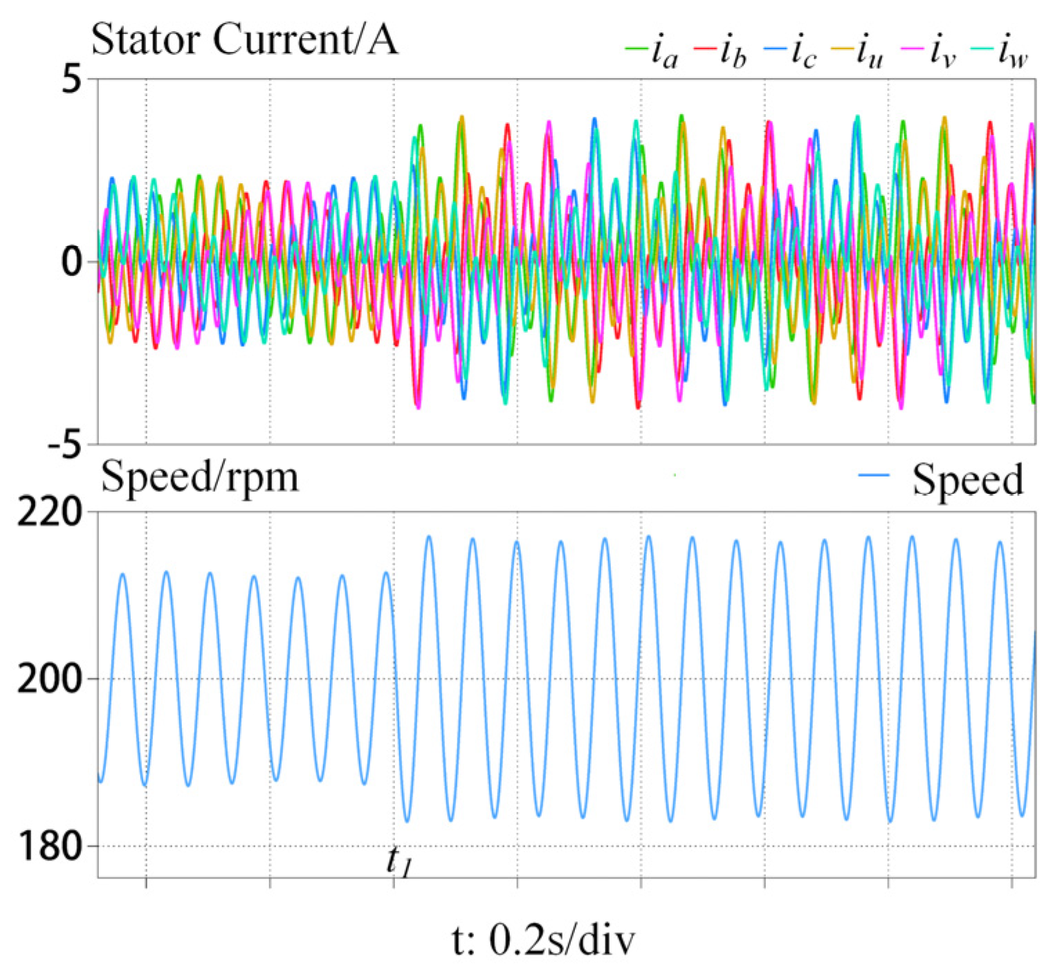
In the suppression of speed oscillation section, t1 is defined as a sudden change in load to 3 Nm, and t2 is defined as a sudden change in load from 3 Nm to 0. As shown in Figure 11, the currents and speed of the DTP–PMSM exhibit oscillations during open-loop V/f control, with an oscillation frequency of 14.094 Hz, which is consistent with previous analysis in Equation (12).
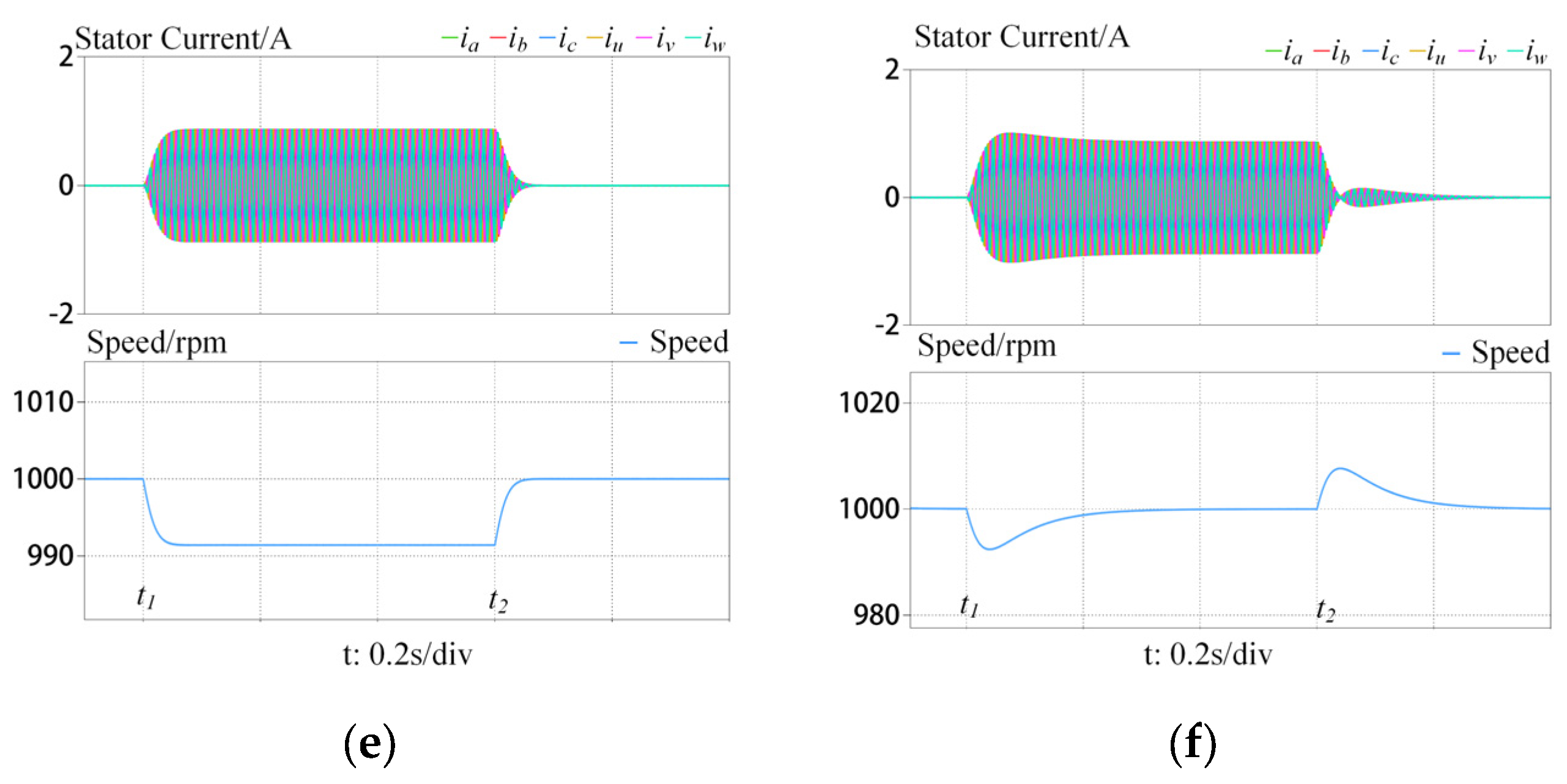
Figure 12a,c,e show the loading 3 Nm and unloading experiments of DTP–PMSM with active power feedback control at 200 rpm, 500 rpm, and 1000 rpm, respectively. The speeds, current ia, and current iu have excellent dynamic characteristics and no overshoot or oscillation during sudden load changes. However, the speeds have small steady-state errors. Thus, to eliminate the steady-state errors in speed, active power is fed back through a 0.25 Hz first-order HPF, and the simulation results are shown in the Figure 12b,d,f. The speeds can maintain the given speed without error after load switching and the currents dynamics are not affected.
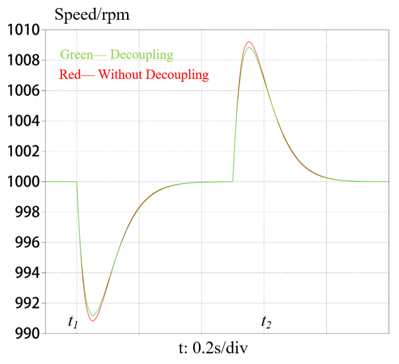
Figure 13 shows the comparative experiment of the DTP–PMSM when decoupled and uncoupled. Decoupling is based on the principle of Equation (3) applied as feedforward. The speed fluctuation with decoupling is smaller than that without decoupling, indicating the effectiveness of proposed decoupling method.
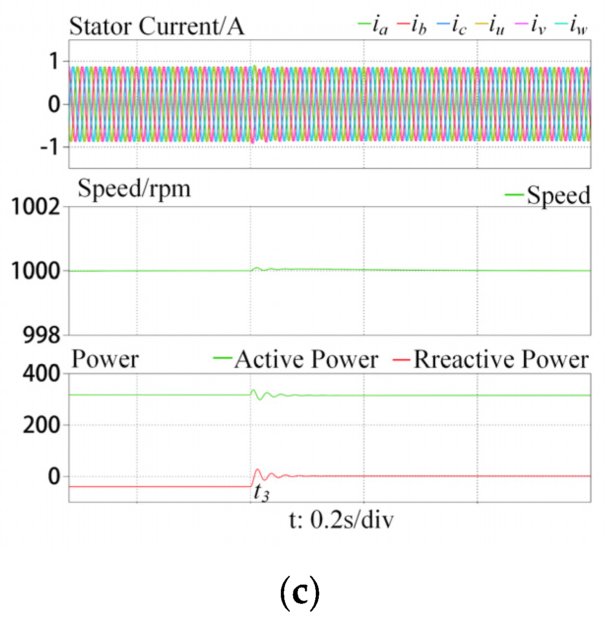
In the reactive power control section, on the basis of active power feedback, the reactive power control algorithm continues to be used, and the simulation results are shown in Figure 14. When comparing before and after the addition of the reactive power control algorithm, it does not affect the active power but can reduce the reactive power to 0, decrease the current, and increase the power efficiency of the inverter side.

4.2. Experimental Results

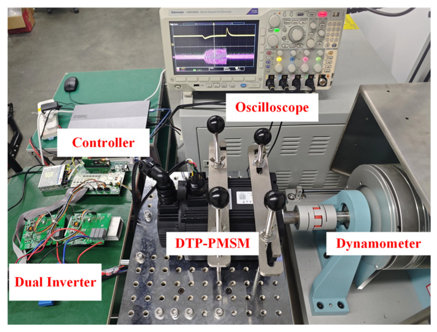
To verify the proposed model and power control strategy, a DTP–PMSM under V/f control framework is set up, shown in Figure 15, and the parameters are presented in Table 2. The experiments are designed as (1) DTP–PMSM under open-loop V/f control, (2) active power feedback control verification, and (3) reactive power control verification.
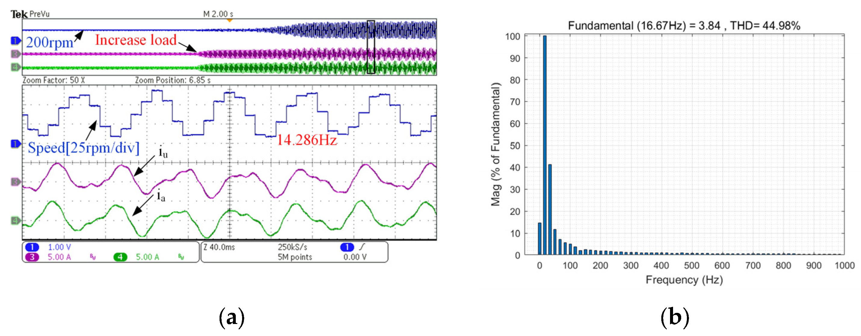
In the DTP–PMSM under an open-loop V/f control section, Figure 16 shows the loading 3 Nm experiment of the DTP–PMSM at 200 rpm. The experiment was conducted according to the diagram shown in Figure 3. The speed oscillation of the DTP-PMSM is 14.286 Hz, which is almost coincides with the previous analysis in Equation (12). The currents ia and iu also exhibit oscillations and distortions. Based on the analysis of current ia, the THD reaches 44.98%. The oscillation frequency is determined by inertia and q-axis inductance, and the inaccuracy of parameters causes oscillation frequency to deviate slightly from theoretical value.
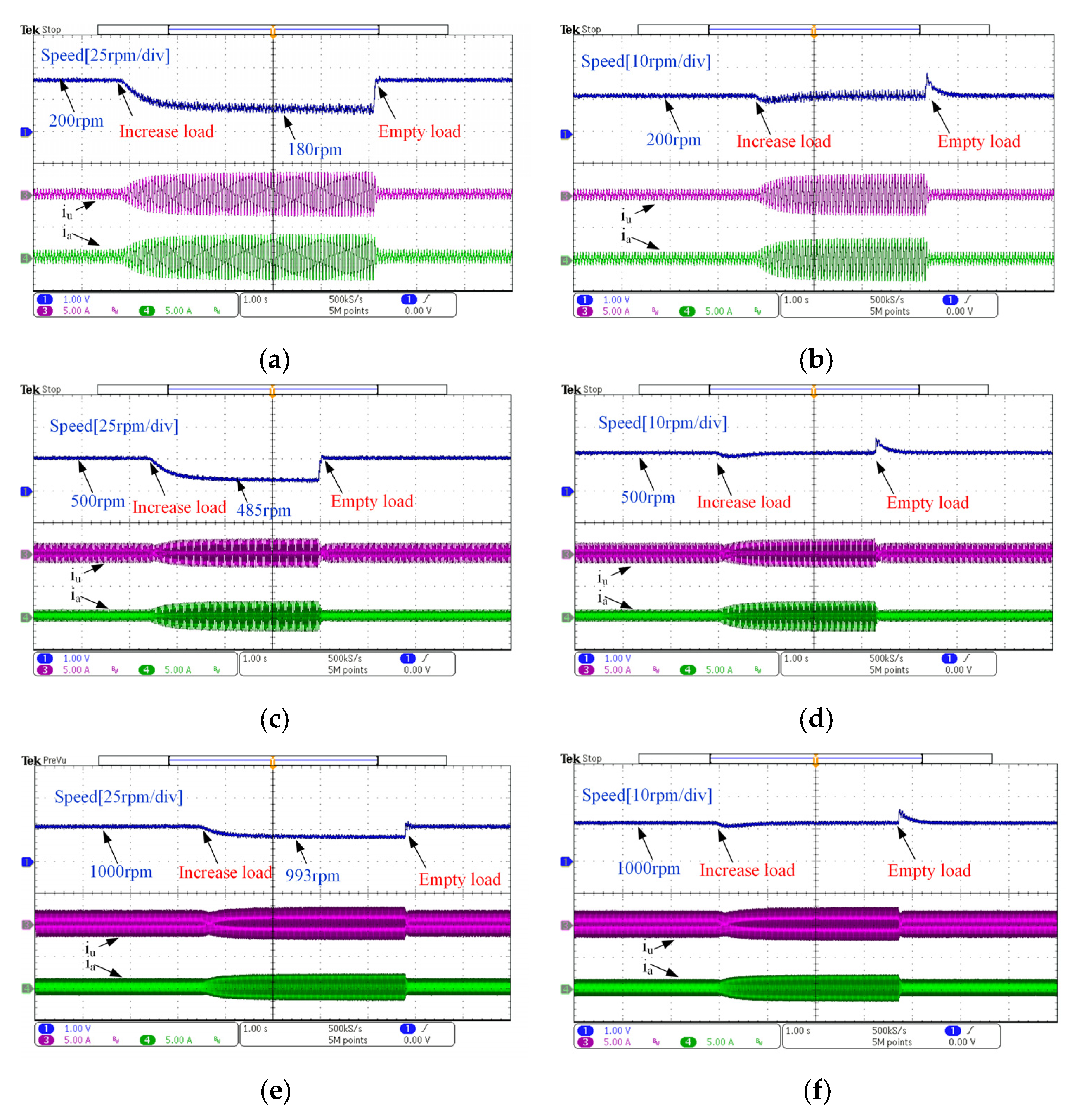
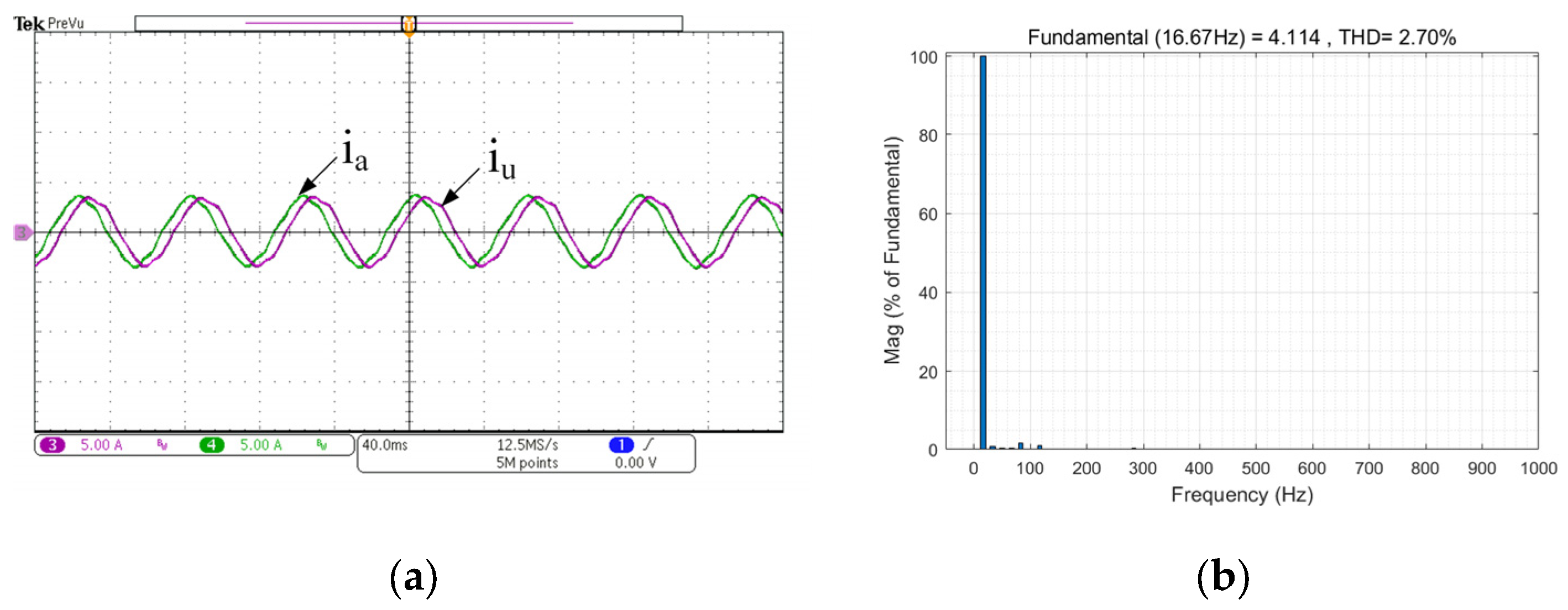
In the active power feedback control section, the implementation steps of active power feedback control are as follows: firstly, the output current iabc/iuvw of the converter is multiplied by the modulation voltage vabc/vuvw to obtain active power. Then, the design of power feedback parameters k1 and k2 through Equations (17) and (18). Finally, the active power and power feedback parameters are fed back into the speed control, as shown in Figure 5. Figure 17a,c,e show the loading 3 Nm and unloading experiments of the DTP–PMSM with active power feedback control at 200 rpm, 500 rpm, 1000 rpm, respectively. The speeds and currents ia and iu have excellent dynamic characteristics and no overshoot or oscillation during sudden load changes. Furthermore, Figure 18a shows the steady-state currents ia and iu of Figure 17a, which do not oscillate and have a THD of 2.70%, as shown in Figure 18b. However, the speeds have small steady-state errors. Thus, to eliminate the steady-state error in speed, active power is fed back through a 0.25 Hz first-order HPF, and the experimental results are shown in the Figure 17b,d,f. The speeds can maintain the given speed without error after load switching and the currents dynamics are not affected.
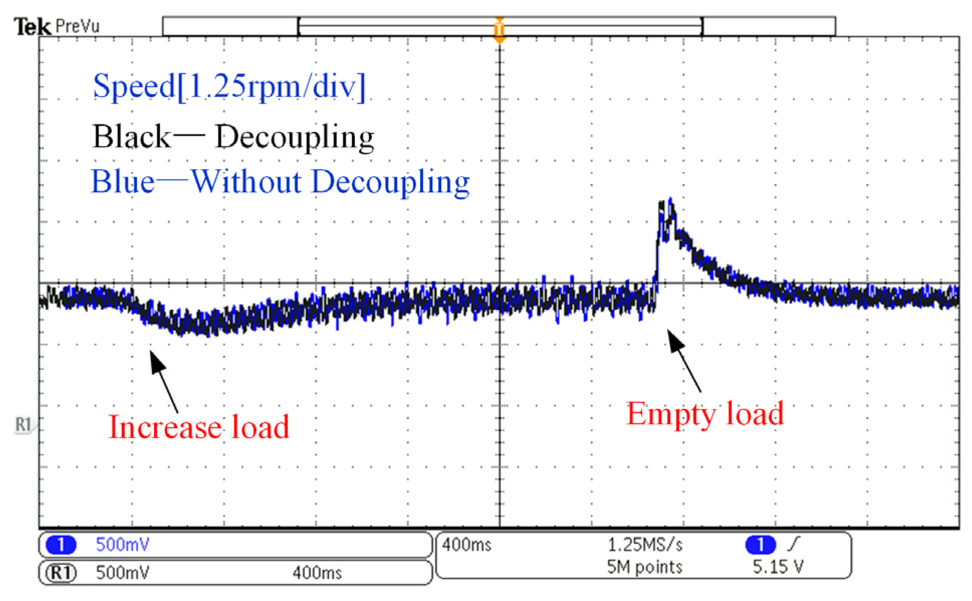
Figure 19 shows the comparative experiment of the DTP–PMSM when decoupled and uncoupled. Decoupling is based on the principle of Equation (3) applied as feedforward. The blue curve (uncoupled) fluctuates slightly more than the black curve (decoupled), indicating the effectiveness of the proposed decoupling method in Equation (3).
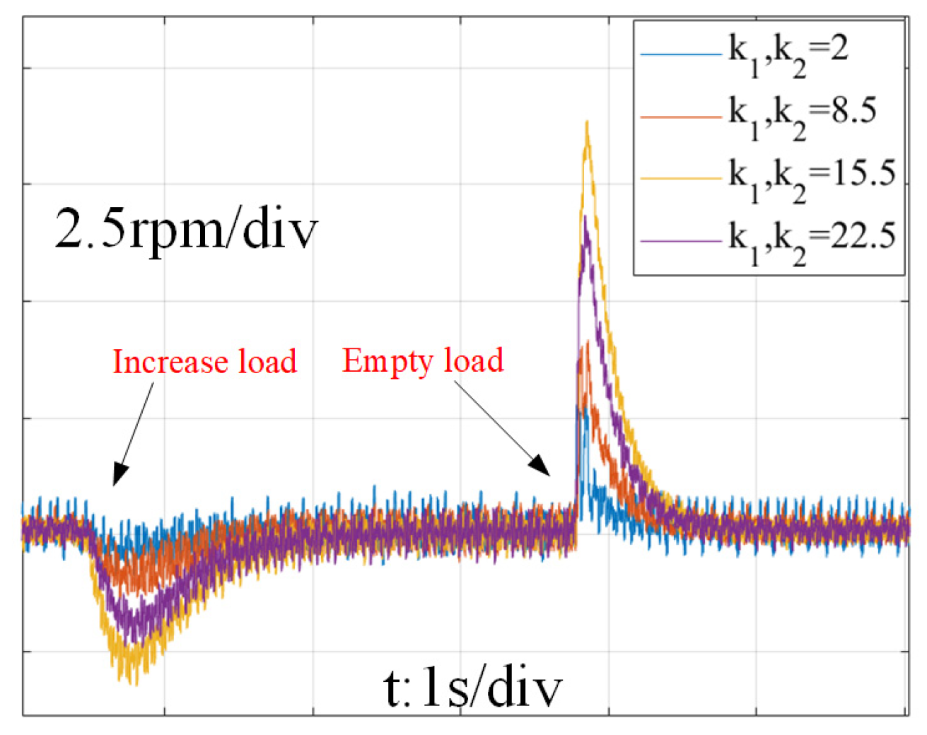
Figure 20 shows the comparative experiments with different power feedback coefficients k1 and k2. When k1 = k2 = 2, the speed exhibits oscillations in both steady-state and sudden load changes. When k1 = k2 = 15.5, 22.5, the speeds fluctuate more than 2.3 rpm at increasing load and more than 6 rpm at emptying load with the longest recovery time to the steady state. The speed has fluctuations not exceeding 2.5 rpm and no oscillation at the moment of sudden load change when k1 = k2 = 8.5, which are designed by Equations (17) and (18).
In Figure 21, compared with the current feedback method (black curve) [17], the speed with power feedback (blue curve) has no oscillation and is more stable. Conversely, the speed with current feedback has larger fluctuations and has oscillation and bigger overshoot at emptying load.
In brief, the active power feedback effect is quantified, and the corresponding coefficient can be designed to solve the issue of poor parameter selection and poor performance with a power-RPM reduced-order model. It coincides with the previous analysis in Section 3.1.
In the reactive power control section, the implementation steps of reactive power control as shown in Figure 7. The output current iabc/iuvw of the converter is multiplied by the modulation voltage vabc/vuvw to obtain reactive power. The reactive power droop coefficient m1, m2 does not affect the stability of the system and can be selected as 1. In Figure 22, the reactive power is independent of active power, whether the reactive power droop control is employed. The reactive power is reduced to 0 for the inverter, when the reactive power droop control is employed. Moreover, the current amplitude drops from 3.6 A to 2.05 A at 200 rpm, from 2.6 A to 2.05 A at 500 rpm, and from 2.1 A to 2.0 A at 1000 rpm. The amplitude of the current is significantly reduced, indirectly improving the efficiency of the motor and having good dynamic performance without any impact on the speed. It coincides with previous analysis in Section 3.2. It means that reducing the current generates a large torque, thereby improving the efficiency of the motor.

5. Conclusions

This paper proposes a power-RPM reduced-order model and power control strategy of DTP–PMSM in a V/f control framework for oscillation suppression of rotor speed. The proposed reduced-order model of the PMSM under a V/f control framework is established in the perspective of power and speed. Furthermore, the speed oscillation and active damping effect of active power feedback can be quantified in theory, compared to the fuzzy active damping assessment of traditsional methods in the higher-order models. Moreover, in the proposed power control strategy, the reactive power droop control is inserted to achieve high power quality and approach the TPA. In both theory and experimental results, the DTP–PMSM with proposed strategy achieves a more stable operation with higher current quality, lower speed ripple, more smooth and quick dynamics respond in speed, power, and current, when compared to traditional strategies. Moreover, it is a suitable way to model and control synchronous motors, such as other kinds of PMSMs and induction generators.

Author Contributions

R.S. and Y.W. wrote the original manuscript, designed the experiment, and carried out the test; H.D. offered guidance and project supervision; X.L. provided the necessary materials and equipment support; and review and editing of the paper were mainly carried out by Y.G. All the authors discussed the results and commented on the manuscript. All authors have read and agreed to the published version of the manuscript.

Funding

This work was supported in part by the National Natural Science Foundation of China under grant 52277182, in part by the Major Talent Program of Guangdong Province (2019QN01L109).

Data Availability Statement

The original contributions presented in the study are included in the article, and further inquiries can be directed to the corresponding author.

Conflicts of Interest

The authors declare that they have no known competing financial interests or personal relationships that could have appeared to influence the work reported in this paper.

References

  1. Zhao, W.; Feng, J.; Tao, T.; Wang, C.; Liu, S. High-Frequency Harmonics and Vibration Reduction for Dual Three-Phase PMSM Using Multiple Randomized SVPWM Strategy. IEEE Trans. Power Electron. 2024, 39, 11455–11467. [Google Scholar] [CrossRef]
  2. Zheng, H.; Pei, X.; Liagas, C.; Brace, C.; Zeng, X. Extended Minimum Copper Loss Range Fault-Tolerant Control for Dual Three-Phase PMSM. IEEE Trans. Ind. Appl. 2024, 60, 6263–6276. [Google Scholar] [CrossRef]
  3. Levi, E.; Barrero, F.; Duran, M.J. Multiphase machines and drives-Revisited. IEEE Trans. Ind. Electron. 2015, 63, 429–432. [Google Scholar] [CrossRef]
  4. Wang, Z.; Yu, K.; Li, Y.; Gu, M. Position sensorless control of dual three-phase IPMSM drives with high-frequency square-wave voltage injection. IEEE Trans. Ind. Electron. 2022, 70, 9925–9934. [Google Scholar] [CrossRef]
  5. Wang, X.; Wang, Z.; Xu, Z. A hybrid direct torque control scheme for dual three-phase PMSM drives with improved operation performance. IEEE Trans. Power Electron. 2018, 34, 1622–1634. [Google Scholar] [CrossRef]
  6. Li, H.S.; Zhou, Y.; Cao, Q.; Zhou, S. Mathematical derivation and analysis of the stability of open-loop control systems for permanent magnet synchronous motors. Chin. J. Electr. Eng. 2014, 1, 36–43. [Google Scholar]
  7. Cheng, A.; Jin, X. A stable V/F control method for permanent magnet synchronous motor drives. In Proceedings of the 2017 IEEE Transportation Electrification Conference and Expo, Asia-Pacific (ITEC Asia-Pacific), Harbin, China, 7–10 August 2017; pp. 1–5. [Google Scholar]
  8. Perera, P.C.; Blaabjerg, F.; Pedersen, J.K.; Thogersen, P. A sensorless, stable V/f control method for permanent-magnet synchronous motor drives. IEEE Trans. Ind. Appl. 2003, 39, 783–791. [Google Scholar] [CrossRef]
  9. Tang, Z.; Akin, B. A new LMS based algorithm to suppress dead-time effects in PMSM V/f drives. In Proceedings of the 2017 IEEE Applied Power Electronics Conference and Exposition (APEC), Tampa, FL, USA, 26–30 March 2017; pp. 3156–3162. [Google Scholar]
  10. Wang, S.; Su, J.; Lu, G.; Yang, G. Decoupling Control for Aviation Dual-Redundancy Permanent Magnet Synchronous Motor with 0° Phase Shift. IEEE Trans. Energy Convers. 2023, 38, 2929–2937. [Google Scholar] [CrossRef]
  11. Tu, W.; Xiao, G.; Suo, C.; Yang, K. A design of sensorless permanent magnet synchronous motor drive based on V/f control. In Proceedings of the 2017 20th International Conference on Electrical Machines and Systems (ICEMS), Sydney, Australia, 11–14 August 2017; pp. 1–5. [Google Scholar]
  12. Lee, K.; Han, Y. MTPA control strategy based on signal injection for V/f scalar-controlled surface permanent magnet synchronous machine drives. IEEE Access 2020, 8, 96036–96044. [Google Scholar] [CrossRef]
  13. Consoli, A.; Scelba, G.; Scarcella, G.; Cacciato, M. An effective energy-saving scalar control for industrial IPMSM drives. IEEE Trans. Ind. Electron. 2012, 60, 3658–3669. [Google Scholar] [CrossRef]
  14. Matsuki, Y.; Doki, S. High stability V/f control of PMSM using state feedback control based on nt coordinate system. In Proceedings of the 2018 International Power Electronics Conference (IPEC-Niigata 2018-ECCE Asia), Niigata, Japan, 20–24 May 2018; pp. 2224–2228. [Google Scholar]
  15. Kim, W.J.; Kim, S.H. A simple MTPA operation scheme for V/f control of PMSMs. In Proceedings of the 2019 10th International Conference on Power Electronics and ECCE Asia (ICPE 2019-ECCE Asia), Busan, Republic of Korea, 27–30 May 2019; pp. 1297–1302. [Google Scholar]
  16. Saleh, S.A. Testing a $ V/f $ Control for Permanent Magnet Synchronous Motor Drives with Wavelet Modulated Power Electronic Converters. In Proceedings of the 2023 IEEE Industry Applications Society Annual Meeting (IAS), Nashville, TN, USA, 29 October–2 November 2023; pp. 1–8. [Google Scholar]
  17. Zhang, S.; Kang, J.; Yuan, J. Analysis and suppression of oscillation in V/F controlled induction motor drive systems. IEEE Trans. Transp. Electrif. 2021, 8, 1566–1574. [Google Scholar] [CrossRef]
  18. Tao, L.; Sun, J.; Tian, Z.; Huang, M.; Zha, X.; Gong, J. Speed-sensorless and motor parameters-free starting method for large-capacity synchronous machines based on virtual synchronous generator technology. IEEE Trans. Ind. Electron. 2020, 68, 6607–6618. [Google Scholar] [CrossRef]
  19. Zhong, Q.C. AC Ward Leonard drive systems: Revisiting the four-quadrant operation of AC machines. Eur. J. Control 2013, 19, 426–435. [Google Scholar] [CrossRef]
  20. Vidlak, M.; Gorel, L.; Makys, P. Performance evaluation, analysis, and comparison of the back-EMF-based sensorless FOC and stable V/f control for PMSM. In Proceedings of the 2022 International Symposium on Power Electronics, Electrical Drives, Automation and Motion (SPEEDAM), Sorrento, Italy, 22–24 June 2022; pp. 318–323. [Google Scholar]
  21. Tang, Z.; Li, X.; Dusmez, S.; Akin, B. A new V/f-based sensorless MTPA control for IPMSM drives. IEEE Trans. Power Electron. 2015, 31, 4400–4415. [Google Scholar] [CrossRef]
  22. Kim, W.J.; Kim, S.H. MTPA operation scheme with current feedback in V/f control for PMSM drives. J. Power Electron. 2020, 20, 524–537. [Google Scholar] [CrossRef]
  23. Liu, T.; Zhu, Z.Q.; Wu, Z.Y.; Stone, D.; Foster, M. A simple sensorless position error correction method for dual three-phase permanent magnet synchronous machines. IEEE Trans. Energy Convers. 2020, 36, 895–906. [Google Scholar] [CrossRef]
  24. Choo, K.M.; Won, C.Y. Flying start of permanent-magnet-synchronous-machine drives based on a variable virtual resistance. IEEE Trans. Ind. Electron. 2020, 68, 9218–9228. [Google Scholar] [CrossRef]
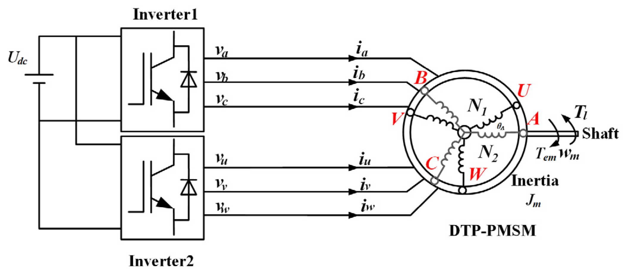
Figure 1. Inverter-driven DTP–PMSM.
Energies 17 04563 g001
Figure 2. Independent sub-PMSM and inverter. (a) Equivalent circuit. (b) The voltage vector.
Energies 17 04563 g002
Figure 3. DTP–PMSM under a V/f control framework.
Energies 17 04563 g003
Figure 4. Pole locus when speed changes at the rated torque.
Energies 17 04563 g004
Figure 5. Power feedback block diagram.
Energies 17 04563 g005
Figure 6. Unity step response from δwref to δwme at rated torque when applying power feedback. (a) Without HPF. (b) With HPF.
Energies 17 04563 g006
Figure 7. Pole loci of DTP–PMSM under the V/f control flamework (a) without feedback, (b) with current feedback [17], and (c) with power feedback.
Energies 17 04563 g007
Figure 8. Reactive power control strategy.
Energies 17 04563 g008
Figure 9. Pole locus of DTP–PMSM under V/f control flamework when m1 is increased.
Energies 17 04563 g009
Figure 10. Proposed power control strategy of dual three-phase PMSM in V/f control framework.
Energies 17 04563 g010
Figure 11. V/f control oscillation phenomenon in DTP-PMSM without the power feedback control.
Energies 17 04563 g011
Figure 12. DTP–PMSM with active power feedback control (a) at 200 rpm, (b) with a HPF at 200 rpm, (c) at 500 rpm, (d) with a HPF at 500 rpm, (e) at 1000 rpm, and (f) with a HPF at 1000 rpm.
Energies 17 04563 g012aEnergies 17 04563 g012b
Figure 13. Speed with decoupling of two windings at 1000 rpm.
Energies 17 04563 g013
Figure 14. The DTP–PMSM with proposed power control (a) at 200 rpm, (b) at 500 rpm, and (c) at 1000 rpm.
Energies 17 04563 g014aEnergies 17 04563 g014b
Figure 15. Experimental platform.
Energies 17 04563 g015
Figure 16. V/f control oscillation phenomenon in DTP–PMSM without the power feedback control. (a) Speed and currents ia and iu. (b) FFT analysis of ia.
Energies 17 04563 g016
Figure 17. The DTP–PMSM with active power feedback control (a) at 200 rpm, (b) with a HPF at 200 rpm, (c) at 500 rpm, (d) with a HPF at 500 rpm, (e) at 1000 rpm, and (f) with a HPF at 1000 rpm.
Energies 17 04563 g017
Figure 18. Currents at 200 rpm. (a) Current ia and iu. (b) FFT analysis of ia.
Energies 17 04563 g018
Figure 19. Speed with decoupling of two windings at 1000 rpm.
Energies 17 04563 g019
Figure 20. Speed with different power feedback coefficients k1 and k2 at 1000 rpm.
Energies 17 04563 g020
Figure 21. Speed with power feedback (blue curve) and current feedback (black curve) at 1000 rpm.
Energies 17 04563 g021
Figure 22. DTP-PMSM with proposed power control (a) at 200 rpm, (b) at 500 rpm, and (c) at 1000 rpm.
Energies 17 04563 g022
Table 1. Method comparison in the V/f control flamework.
Control MethodWorksModelOscillation Analysis and SuppressionThe Difficulty Level of Feedback Parameter DesignPower
V/f control without active damping[6]Fourth-order model in sub-PMSMRoot locus analysis. Unable to quantify oscillations and damping ratio. Unable to suppress oscillation.None.Poor power factor.
V/f control with current feedback[17]Fourth-order model in sub-PMSMBode diagram analysis. Unable to quantify oscillations. The design of current feedback parameters cannot be quantified and is complex. Poor suppression of oscillation effects.Design based on bode diagram and unable to quantify. Complex.Poor power factor.
V/f control with power feedback.[8,11,12]Fourth-order model in sub-PMSMRoot locus analysis. Unable to quantify oscillations and damping ratio. Excellent oscillation suppression effects.Design based on root locus diagram and unable to quantify. Complex.Poor power factor.
V/f control with Power-RPM Reduced-order ModelProposedSecond-order model in sub-PMSMPole loci analysis, quantify oscillations and damping ratio in Power-RPM Reduced-order Model. Excellent oscillation suppression effects.Design based on Power-RPM Reduced-order Model and quantify. Simple.High power factor.
Table 2. System parameters.
ParametersDescriptionsValues
ψfRotor flux0.23396 Wb
Lqq-axis inductance4.13 mH
Ldd-axis inductance3.13 mH
Lqqq-axis coupling inductances between two windings2.22 mH
Lddd-axis coupling inductances between two windings1.47 mH
RsStator resistance0.5 Ω
nMotor pole pairs5
JmThe total equivalent inertia of the machine and load0.070 kg·m2
nrareRated speed1000 rpm
freSystem oscillation frequency14.286 Hz
k1Power feedback coefficient8.5
k2Power feedback coefficient8.5
m1/m2reactive power droop coefficient1
Disclaimer/Publisher’s Note: The statements, opinions and data contained in all publications are solely those of the individual author(s) and contributor(s) and not of MDPI and/or the editor(s). MDPI and/or the editor(s) disclaim responsibility for any injury to people or property resulting from any ideas, methods, instructions or products referred to in the content.