Article

Influence of Volute Casing Design Methods and Changes in Geometric Parameters on Pump Operation

1
Department Energy Conversion Engineering, Wroclaw University of Science and Technology, 50-370 Wroclaw, Poland
2
Independent Researcher, 50-370 Wroclaw, Poland
*
Author to whom correspondence should be addressed.
Energies 2024, 17(18), 4590; https://doi.org/10.3390/en17184590
Submission received: 4 August 2024 / Revised: 6 September 2024 / Accepted: 9 September 2024 / Published: 13 September 2024
(This article belongs to the Section I: Energy Fundamentals and Conversion)

Abstract

:
This article presents results from research whose purpose is to determine the impact of two main factors on the operational efficiency of a double-entry centrifugal pump. The first factor is the design methods, and the second is changes in the geometric parameters for the volute casing. The results of the numerical simulation were experimentally validated on a test stand. Within this study, volute casings were designed according to the constant velocity method and method of conservation of angular momentum of the flow. The geometric parameters were selected according to the recommendation of A. Stepanoff and A. Lomakin. Next, the following geometric parameters were changed: inlet diameter, inlet width, cross-sectional area, shape of the volute casing’s cross-section (trapezoidal vs. round) and the opening angle of the volute casing’s walls. A comparison of the two methods showed that the biggest difference between them is the influence on the shape of the pump characteristic curve. Altering the geometric parameters in trapezoidal or round volute casing cross-sections had minimal impact on the pump head and efficiency.

1. Introduction

Currently, an important issue often undertaken by many research centres is the minimisation of energy consumption in all industries. One way to achieve this goal is to reduce the energy consumption of devices by improving their design. One of the most energy-consuming machines are centrifugal pumps. Among the centrifugal pumps, there are double-entry pumps that are widely used in hot and cold water installations, refrigeration systems, power plants, the metallurgical industry and chemical processes. To improve the operation of the pump, the design of the impeller is most often changed, which has the greatest impact on the operation of the pump. However, it is a mistake not to take into account the volute casing and cooperation of the impeller and the volute casing. The liquid from the impeller must flow through the volute casing with the lowest possible losses throughout the recommended operating range. Therefore, researching the volute casing is a necessary action that can improve the efficiency of centrifugal pumps.
The methodology for designing a volute casing has not been sufficiently described. There are two methods for designing a volute casing: the constant velocity method and the method of conservation of angular momentum of the flow. However, in the available literature, there is no information on which method is better to use to obtain the necessary operation parameters of the pump. There are also no clear guidelines regarding the selection of geometric parameters of the volute casing and their values. Each of the methods presented above allows different cross-sectional areas perpendicular to the direction of flow to be obtained and indicates the tendencies of their change along the volute casing.
In addition, there are no clear guidelines on which method to use depending on the pump operating parameters. Only Gulich [1] recommends using the following design approach: (a) for nq < 25 … 35 using the constant velocity method, or (b) for nq > 25 … 35 using the method conservation of angular momentum of the flow, where nq is the specific speed of the pump (1).
n q = n · Q H 3 4
The conservation of angular momentum of the flow method assumes that the velocity in the volute casing decreases proportionally with the increase in the distance from the tongue of the volute in accordance with Equation (2) [2]:
c u · r = c o n s t ,
where cu—peripheral component of the absolute velocity at a distance r from the rotation axis.
When designing a volute casing using the constant velocity method, we assume a simplification in which the cross-sectional areas increase in proportion to the angle at which a given cross-section is placed about the tongue of the volute casing. According to Stepanoff [3], the average velocity is determined from Formula (3):
c 3 = K 3 · 2 g H ,
where K 3 —average velocity coefficient in the volute casing [3]; its value depends on nq.
Many authors use one of the methods and describe their recommendations regarding the selection of geometric parameters of the volute casing. On this basis, groups of supporters of particular methods can be identified. Supporters of the constant velocity method include Aizenstein M. [4], Stepanoff A. [3] and Lobanoff V. [5]. However, these authors have different approaches to the selection of the inlet width (b3) and the inlet diameter of the volute (d3). The supporters of the method of conservation of angular momentum of the flow are Pfleiderer C. [6], Lomakin A. [2], Polotskiy I. [7], Mashyn A. [8], Spiridonov E. [9] and Mihajlow A. and Maliushenko V. [10]. Among these authors, large discrepancies can also be found in the approach to the selection of geometric parameters of the volute casing.
Chang Ho Son et al. [11] studied changes in the cross-sectional area of volute casings designed by using the principle of the Archimedean spiral according to Stepanoff [3]. The authors increased and decreased the cross-sectional area by 10% and 30%. The analysis of the conducted research shows that as the cross-sectional area increases, the head–capacity curve (Q-H curve) and efficiency curve become flatter, and when the area decreases, the curvature of the characteristics increases. These data are confirmed by the work of Yi Tao et al. [12]. The findings indicated that enlarging the cross-sectional area of the volute slightly reduces the efficiency at the optimal operating point (1.0Qopt). However, under a non-optimal flow rate, the efficiency improves. A volute casing with a larger cross-sectional area causes a broader range of high efficiency.
Beena D. Baloni et al. [13] compared volute casings made using the conservation of angular momentum of the flow method and the constant velocity method for a centrifugal fan. The authors concluded that the flow in a volute casing designed according to the constant velocity method provides better flow conditions. However, the study used a compressible medium, so the results should be verified for water.
Tao Wang et al. [14,15] presented their method of designing a volute casing, wherein the lowest hydraulic losses in the volute casing are achieved. According to the authors, volute casings designed using the conservation of angular momentum method are imperfect in operation. The authors claim that the actual velocity distribution does not conform to the theory of conservation of angular momentum.
The authors of [16] investigate a low-specific-speed centrifugal pump using the constant velocity method. The volute throat area was decreased by 25 and 50% during the research. The decrease in area led to the head–capacity curve becoming steeper. Movement of the best efficiency point (BEP) to the design point was also observed. Furthermore, the article investigated the impact of the volute gap. The authors attribute the improved pump performance (higher head delivered by the impeller) to the improved slip factor across all flow rates. The authors compared pumps with volute casings designed by one method and did not set for themselves the task of comparing different design methods. J. H. Kim et al. [17] changed the design of the impeller and volute casing. The volute casing that was shaped like a trapezoid and was designed according to the Stepanoff theory cooperated best with the modified impeller. Sunsheng Yang et al.’s [18] research showed that it is better to use a round cross-sectional shape for the volute casing. The difference in pump efficiency for rectangular and trapezoidal shapes is insignificant. The authors compared only the volute casing according to the Stepanoff theory.
Chunjun Ji et al. [19] studied the main factors related to the diffuser and volute affecting the performance of a centrifugal compressor. The authors obtained an increase in polytropic efficiency of 4.5% due to changes in the cross-sectional area and shape, the shape of the tongue and the connection of the outlet pipe with the volute. Studying the mixed flow pump, the authors of [20] concluded that the main factors for the satisfactory design of the volute are the variation pattern of the volute cross-sections and the shape of the volute tongue. Instead, the shape of the volute cross-section has a minor effect on the volute performance. Zhenmu Chen et al. [21] also researched the optimum design of the volute tongue shape. The change in the volute tongue led to an increase in the pump efficiency from 72.7% to 75.01%.
In another article [22], the authors also changed the geometric parameters of the volute casing. The study aimed to optimise the geometry of the volute casing to achieve optimal mechanical properties of the pump casing. The geometry has been changed taking into account the condition that the stress should not be beyond the material strength given the fragility of cast iron. Optimised volute casings have high mechanical capability but also have negligible reduced performance and efficiency due to changes in the hydraulic design of the volute-shaped segment.
The volute casing is often the object of research in studying pulsations. To investigate the pressure characteristics on the inner wall of the volute casing, the authors of [23] installed a multichannel pressure sensor. The authors claim that the intensity of the pressure pulsation decreases with the increase in the rotational speed. In the research reported in [24], the authors concluded that an increase in the area of the volute throat reduces the intensity of turbulence in the pump. It leads to a reduction in pump pressure pulsations as a result of diminishing the rotor–stator interaction. Changing the tongue types is also an important element that affects the parameters of the pump [25]. Dong R. et al. [26] investigated the gap between the tongue and the impeller. Increasing the gap up to about 20% of the impeller radius led to a decrease in the level of noise and vibration of the pump, while a further increase led to a negative effect on performance.
Daniel O. Baun et al. [27] studied the influence of moving the impeller relative to the geometrical centre of a circular volute in a centrifugal pump. At the best relative position, the authors achieved an increase in efficiency compared to the base positions for the circular and spiral volutes. While studying the issue of head–flow curve instability in centrifugal pumps, the authors of [28] concluded that the greatest losses are concentrated on the volute tongue and volute diffuser at high flow rates. Studies [29] of the influence of the volute inlet diameter of low-specific sewage pumps showed a small influence on the speed distribution of the impeller and a large influence on the volute casing.
In article [30], the authors have already tried to determine the influence of the geometric parameters of the volute casing on the pump operation. It considered a different centrifugal pump with a similar specific speed for the volute casing (nq = 23) but larger geometrical parameters of the pump flowing part (the impeller diameter in article [30] is 850 mm and in the present article is 270 mm). The completed models were not enough to accurately determine the influence of the geometric parameters. Different forms of cross-sections and angle openings of the walls of the volute casing were not considered. A numerical study was carried out without confirmation on an experimental stand [30]. Therefore, there is a need for the continuation and expansion of the study of the influence of volute design, especially with validation in the form of an experiment.
The influence of the geometry of the outlet casing also noticeably affects the operating parameters of impellers. In article [31], Lu Rong et al. investigate a high-speed submersible axial flow pump. One of their focuses was the cooperation of the diffuser with the impeller. The flow loss was investigated using entropy generation. At a nominal flow rate, losses are mostly concentrated at the impeller outlet and inside the diffuser. By changing the design of the impeller, the authors increased the target efficiency by 8.34%. It is worth noting that article [31] considers a submersible axial pump without a volute. Loss characterisation in a centrifugal impeller is studied in detail in the article by Bo Chen et al. [32]. With the help of the PIV experiment, the locations and distribution of the nearest vortex formations were established.
The presented literature review indicates the importance of researching the operating process of pumps with volute casings. The literature analysis showed insufficient determination of the impact of the geometrical parameters and the adopted method of calculating the volute casing on the energy properties of the pump. Therefore, this article aims to research and analyse the impact of the volute casing on the double-entry pump operation parameters.

2. Research Methodology

2.1. Object of Research

The object of the research is a double-entry centrifugal pump with optimal operation parameters: flow rate Qopt = 105 m3/h, head H = 25 m, rotational speed n = 1460 rpm, specific speed for the volute casing nq = 23 and for impeller nq = 16.
Based on the reference pump, 12 models of volute casings were created using the constant velocity method and the method of conservation of angular momentum of the flow. In addition to the design methods, this research took into account the geometric parameters of the volute casing (Table 1) selected according to the recommendations of Stepanoff A. [3] and Lomakin A. [2]. The following geometric parameters were changed in the volute casing (Figure 1): volute casing inlet width b3, volute casing inlet diameter d3, the shape of cross-sections and the opening angle of the walls.
The location of the tongue in the volute casing was changed due to the change in the inlet diameter to the volute (d3). The position of the diffuser outlet cross-section was constant for all volute casings. The diffuser parameters of the new volute casings correspond to the reference one.

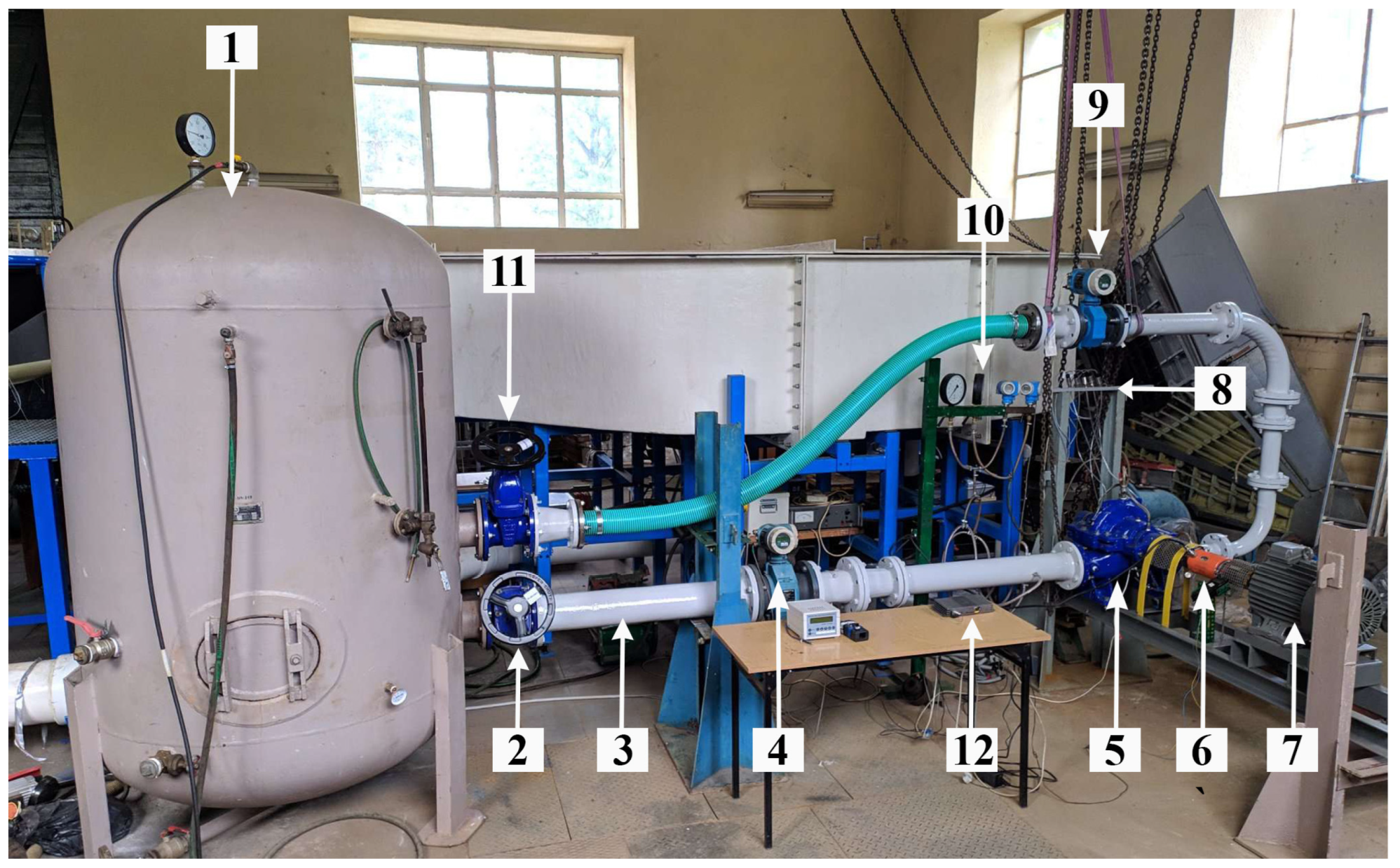
2.2. Experimental Research

In order to validate the numerical model of the reference pump, an experimental stand was built. The experiment aimed to compare the results of the numerical simulation of a double-entry pump with the pump operating parameters obtained during a real experiment.
The experimental stand is shown in Figure 2 and was constructed as a closed circuit in accordance with the recommendations of ISO 9906 [33]. The main characteristics of the laboratory measurement equipment are presented in Table 2. The relative marginal errors of the flow rate, head, mechanical power and efficiency are 0.5%, 0.3%, 1.2% and 1.4%, respectively.
The main element of the stand was the pump assembly, which consisted of a 10 kW electric engine and the tested double-entry pump. A frequency converter was used to regulate the pump operation rotation speed.
The experimental stand enables measurement and automatic reading of operating parameters such as the static pressure at the inlet and outlet of the pump, flow rate, torque on the shaft, shaft rotation speed and electrical power. The working medium was clean water at a temperature of 20 °C. The pressure distribution measurement was started after the pump had been running for at least 15 min to obtain stable operating parameters. During the experiment, the liquid temperature and rotational speed were monitored. The measurement data were collected using a specially created recording module. The module converted the analogue signal of the sensors into a digital signal. This signal was sent to the laptop. The obtained data were transformed using a specially developed program to comma-separated values.
The parameters were measured at 13 flow rate points with a difference between adjacent points of 10%. Data from the measuring devices were received every second. For one flow rate point, the measurement time lasted 30 s. Then, the data obtained for 30 s were averaged.

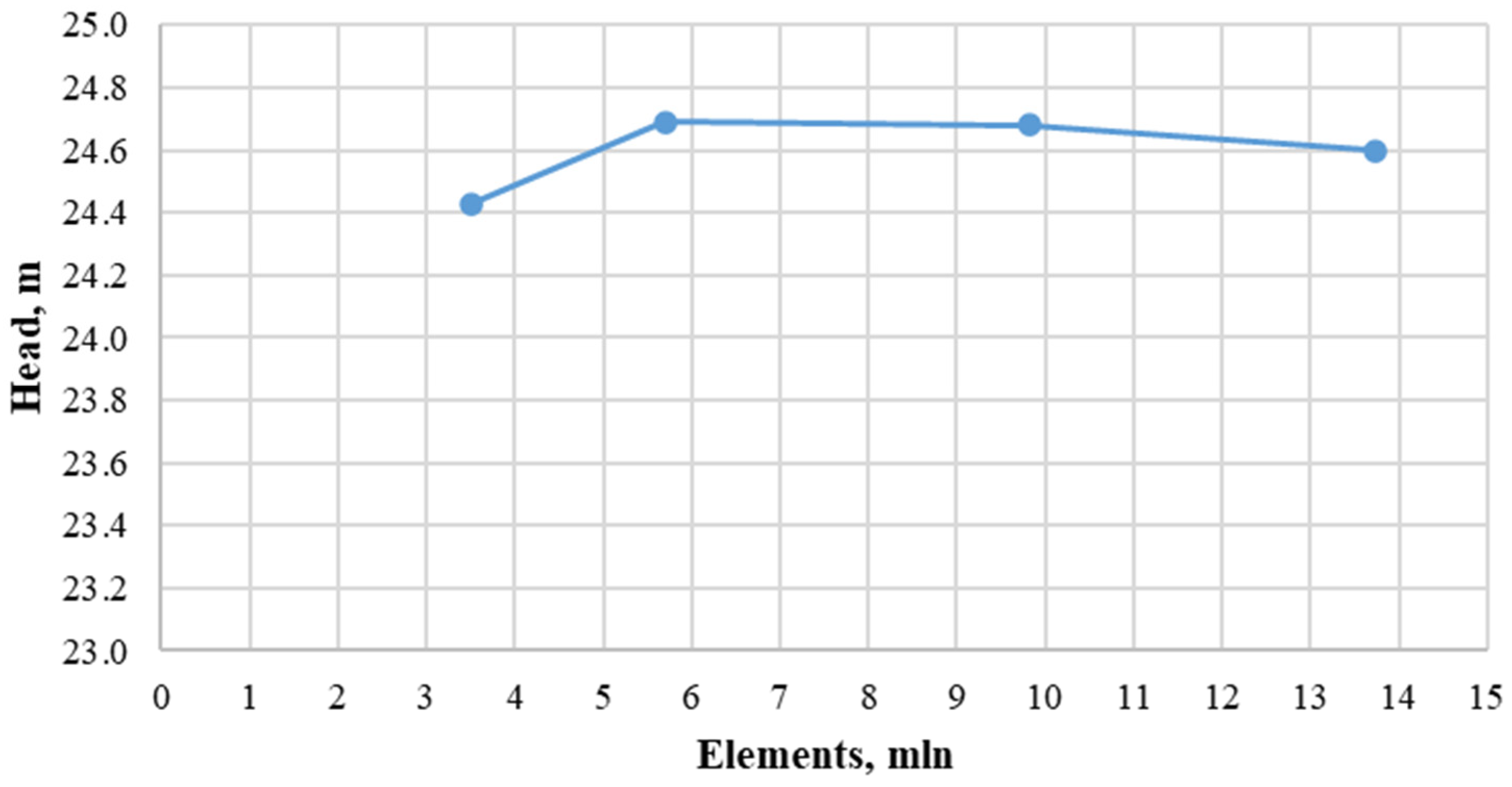
2.3. Numerical Studies

Due to the fact that the volute casing is the main component of the double-entry pump housing, it is not possible to examine all volute casings by changing them in a real pump. That is why numerical simulation was chosen as the main method for examining the volute casing geometry. Numerical research aims to compare the operation parameters of the pump and the operation process of volute casings created using different methods while maintaining different geometric parameters.
The expected result of the research is differences in the pump’s operating characteristics, including the head and efficiency of the pump, hydraulic losses in the volute casing and liquid flow parameters in the cross-sections of the volute casing. Based on the obtained characteristics, an analysis of the influence of the described volute casing design methods and geometric parameters was carried out.
To perform numerical simulation, the geometry of the tested pump was obtained by 3D scanning of a real object. Based on the data obtained, a three-dimensional model of the flow part of the pump elements was built.
The unstructured mesh was generated in Ansys ICEM CFD (Figure 3a). Tetra elements were made in the centre of the flow body, and layers of prisms were used near the walls. The size of the elements provides a recommended Y+ value of 30–300. In order to reduce the elements of the computational grid, the analysed computational area consisted of half of the flow part of the double-entry pump. Half-pump simulations were compared with full-pump simulation results. The difference was less than 0.5%.
The computational model (Figure 3b) consists of an inlet and outlet pipeline, a volute casing, an impeller, an inlet casing and the sidewall gaps (semi-transparent colour). The total number of elements was assumed to be approximately 10 million according to the mesh independence test (Figure 4). The influence of the mesh quality on the calculation time and quantity of the mesh elements on the Y+ value was also taken into account when choosing the final mesh to conduct numerical research.
The pump operation was simulated using Ansys 2022 CFX software. This program discretises the spatial domain using an element-based finite volume. The Rhie–Chow algorithm was used to implement the scheme for the pressure–velocity coupling in CFX.
Steady-state simulations were used. The Reynolds-Averaged Navier–Stokes (RANS) method with the standard k–ε turbulence model was used for simulation. A convergence criterion of 0.0001 was adopted for all equations. The approximate number of iterations every simulation was 2500. A mass flow rate with normal flow direction was specified at the inlet, and an opening pressure and direction were set at the outlet. The interfaces between the rotary and stationary components were stage rotor interfaces.
The pump model with a reference volute was validated on an experimental stand. The deviation of the numerical simulation results from the experiment for the head was 3.5%, and for efficiency, it was 3% at 1.0Qopt, which is an acceptable level of discrepancy for numerical simulation (Figure 5).

3. Research Results and Their Analysis

3.1. Influence of the Volute Casing Design Method

A comparative analysis of 13 tested volute casings was carried out, which demonstrated a significant impact of the design methods on the pump operating parameters. The volute casings were designed in accordance with the constant velocity method and Stepanoff’s geometric recommendations (selection of sizes b3, d3) with a trapezoidal and circular shape of the cross-section.
An example cross-sectional form is shown in Figure 1. For each cross-sectional shape, the volute casings were designed with different wall opening angles: 20, 30 and 40 degrees. The volute casings designed in accordance with the method of conservation of angular momentum of the flow and Lomakin’s geometric recommendations (selection of sizes b3, d3) had identical cross-sectional shapes and wall opening angles as the volute casings made using the constant velocity method. All volute casings were compared with each other and with the reference volute casing.
The impact of the design method was analysed in terms of the pump efficiency and head and hydraulic losses in the volute casing.

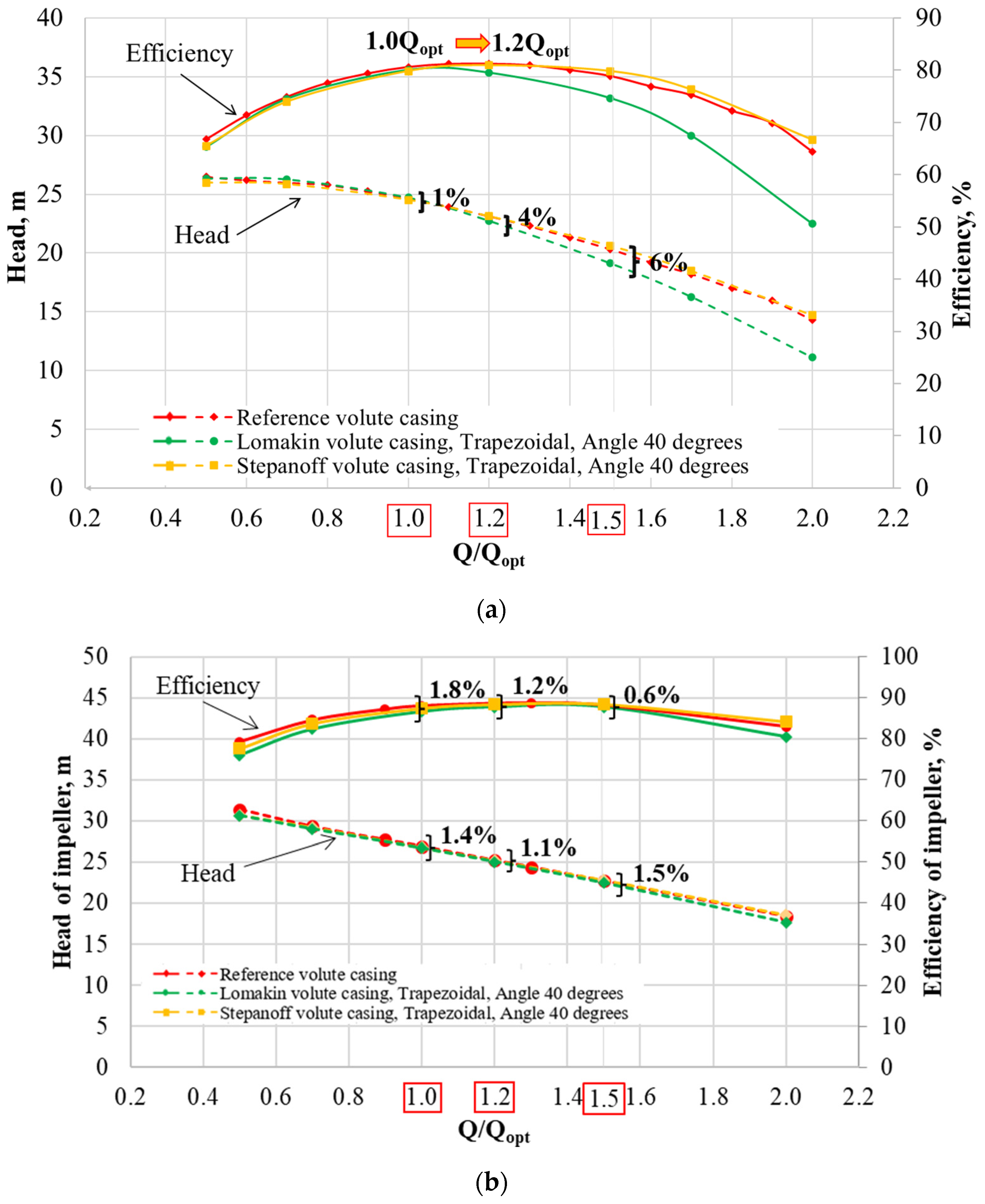
3.1.1. Impact on Pump and Impeller Efficiency

The research results of volute casings at 1.0Qopt are shown in Table 3. As can be seen from Table 3, the change in the pump’s working parameters is insignificant. The pump characteristics for other flow rates are shown graphically in Figure 6a. Figure 6b shows the influence of the volute casing on the impeller’s working parameters.
Figure 6a shows the charts of selected volute casings that best show the influence on the pump characteristics. The tests were carried out in the flow range from 0.5Qopt to 2.0Qopt to check the trend of changing the analysed parameters with the increase in flow rate. Since volute casings with a different wall opening angle and cross-sectional shape give very similar results, they are not shown in Figure 6a.
The results of the simulation of the efficiency of the pump (Figure 6a) with a Stepanoff volute casing (wall opening angle 40°) are presented with a solid curve in yellow, while the results with the Lomakin volute casing (wall opening angle 40°) are presented with a solid curve in green. The results for the pump with the reference volute are shown with a red solid curve.
As can be seen from the analysis of Figure 6a, the pump efficiency in percentage terms does not change significantly. At the optimal point (1.0Qopt), the efficiency of the pump with the Lomakin and Stepanoff volute casings is 80%, and with the reference volute casing, it is 80.5%. Moving to the right side of the efficiency characteristic, it can be seen that the Lomakin efficiency curve slopes steeply. This means that for Lomakin volute casings, the range of the best efficiency is from 1.0Qopt to 1.2Qopt. Since the efficiency curve is steep, it is recommended to operate the pump from 0.9Qopt to 1.2Qopt.
In the case of the curves for the reference and Stepanoff volute casing, they are flatter, which means that the range of best efficiency operation is much larger (from 1.0Qopt to 1.4Qopt and from 1.0Qopt to 1.5Qopt). In Figure 6a, it can be seen that for both the Stepanoff and reference volute casings, the highest efficiency point, which is 81%, shifted to the right from above the optimal efficiency and was located around the 1.2Qopt point.
From Figure 6b, we can see that the volute casing does not have a big influence on the impeller efficiency as well as on the efficiency of all pumps. The largest difference in the impeller efficiency between pumps with the same impeller and different volute casings is 1.8% at 1.0Qopt and 1.2% at 1.2Qopt. The curves practically overlap each other. Therefore, we cannot claim that one of the curves is steeper than the other, as was the case with the curve of pump efficiency (Figure 6a).
Based on the analysis performed, it can be concluded that both the Stepanoff and the reference volute casings are better than the Lomakin volute casing in terms of efficiency. Additionally, moving the best efficiency point (BEP) to the right side indicates oversizing the volute casings. Changing the volute casing did not strongly affect the working parameters of the impeller.

3.1.2. Influence on the Pump and Impeller Head

The results of the influence of the volute casing design method on the head are also shown in Figure 6a,b and Table 3. The curves are shown with dashed curves marked in red, green and yellow, respectively, as in the previous description.
Based on the analysis of Figure 6a, it was found that the head characteristics of the pump with volute casings designed using different methods coincide. The difference in the head value between the pumps with the various volute casings is less than 1% at 1.0Qopt. The head value for the pump with the Stepanoff volute casing is 24.5 m, with the Lomakin volute casing—24.7 m and with the reference volute casing—24.7 m. A visible change in the characteristics can be observed on the right side of 1.0Qopt. At point 1.2Qopt, the difference is 4%. Moving farther to the right, the difference between the head of the pumps with various volute casings increases. It reaches 6% at point 1.5Qopt.
The analysis of Figure 6a shows that within the recommended pump operating range (0.8–1.1Qopt), none of the volute casing design methods significantly affects the pump head.
Figure 6b shows even less impact when changing the volute casing on the impeller head than on the pump head. The difference in the head value is 1.4% at 1.0Qopt. This difference practically does not change in the entire operating range. At 1.5Qopt, the value of the difference is 1.5%.

3.1.3. Cross-Sectional Area of the Volute Casing

The choice of design method affects the determination of the cross-sectional area of the volute casing. As can be seen from Figure 7a, the Stepanoff volute casing, which was designed according to the constant velocity method, has the largest area, while the Lomakin volute casing, which was designed according to the method of conservation of angular momentum of the flow, has the smallest area. According to Figure 7a, the change in cross-section is linear. The sudden change in the angle of inclination of the curves in the Pl360 cross-section is caused by the greater distance between Pl360 and the diffuser outlet and is larger than between the other cross-sections (Figure 7b). Figure 7b shows the arrangement of cross-sections marked on the abscissa of Figure 7a. The differences in cross-sectional areas between the Lomakin and Stepanoff volute casings are 2% at Pl 045 and 4% at Pl 360.

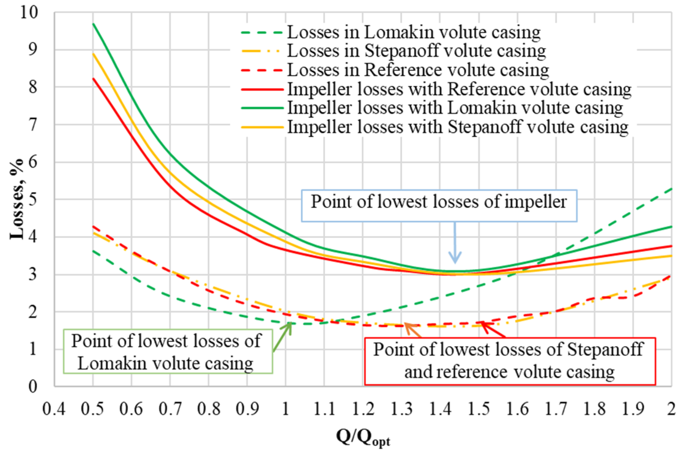
3.1.4. Volute Casing and Impeller Losses

Figure 8 shows the results of hydraulic losses for the reference volute casing (red), Lomakin volute casing (green) and Stepanoff volute casing (yellow) with a wall opening angle of 40° and a trapezoidal cross-sectional shape.
The design method has the most visible impact on hydraulic losses in the volute casing. The difference in losses between the Lomakin and Stepanoff volute casings at 1.0Qopt is 15%.
The small cross-sectional area of the Lomakin volute casing, shown in Figure 7a, causes the lowest value of losses, which is 1.7 m (Figure 8) at 1.0Qopt.
When the flow rate decreases (in Figure 8, moving along the curve to the left from the point of lowest losses of the Lomakin volute casing), the losses increase due to the increase in swirling flow losses. As the flow rate increases (in Figure 8, moving the characteristic to the right), the losses increase. This fact is related to the increase in the velocity of the flow and, accordingly, the increase in losses associated with its friction against the walls. An advantage of the smaller cross-sectional area of the Lomakin volute casing is the coincidence of the point of lowest losses with the optimal operating point at the design flow rate point. However, the disadvantage is the narrow range of work with high efficiency.
In the case of the Stepanoff and the reference volute casings at an optimal flow rate (1.0Qopt), we observe higher hydraulic losses (2.0 m) compared to the Lomakin volute casing (1.7 m). This is due to the larger cross-sectional area. Such an area leads to high swirling flow losses that are greater than those in the Lomakin volute casing. The point of least losses of the Stepanoff volute casing shifts to the right concerning the optimal flow rate. It is 1.63 m at 1.5Qopt. This is due to the low fluid velocities compared to the Lomakin volute casing. They lead to lower friction losses on the volute casing walls. The advantage of a larger cross-sectional area is the widening of the operating range with minimal losses resulting from flow turbulence and low friction losses. Nevertheless, the disadvantage of this method is the displacement of BEP from the designed point in the direction of high flow rate.
The losses in the same impeller cooperating with the Lomakin, Stepanoff and reference volute casings were compared (Figure 8). The loss curves in the impeller are practically parallel to each other. In contrast to the losses in the Lomakin volute casing, in the impeller cooperating with this volute casing, there is no sharp change in the loss at a flow rate higher than 1.0Qopt. The point of the smallest losses in the impeller for all cases of cooperation with the volute casings is 1.45Qopt. The greatest losses are observed in the impeller cooperating with the Lomakin volute casing. The value of the losses is 4.12 m at 1.0Qopt. For the impeller working with the Stepanoff and reference volute casings, this value is 3.87 and 3.66 m. Taking into account the information from Figure 6, it can be noted that changing the parameters of the volute casing has a greater effect on the working process of the volute casing and, as a result, the overall operation of the pump than on the operation of the impeller.

3.1.5. Summary of the Influence of the Volute Casing Design Method

The presented analysis shows that the constant velocity method gives a flatter Q-H curve end efficiency curve of the pump than the method of conservation of angular momentum of the flow. The considered volute casings designed by these methods differ in cross-sectional area. As in articles [11,16], the reduction in the area of the cross-sections led to an increase in the steepness of the head–capacity curve. Designing a volute casing with a large cross-sectional area, in accordance with the constant velocity method (Stepanoff volute casing), leads to displacement of the highest efficiency point to a greater flow rate by reducing friction losses in this flow rate range. This is consistent with the conclusions given in article [12]. The advantage of this method is a wide range of pumps operating with high efficiency (from 1.0Qopt to 1.5Qopt) due to minimal hydraulic losses in this range. The disadvantage of this method is the impossibility of obtaining the smallest losses at the designed operating point. A summary of the compared operating parameters of the volute casings and pump is presented in Table 4.
Volute casings designed using the method of conservation of angular momentum of the flow will have a small cross-sectional area (Lomakin volute casing). As a result, we obtained lower hydraulic losses than in the Stepanoff volute casing. However, the negative effect is a small range of pumps operating with high efficiency (from 1.0Qopt to 1.2Qopt).

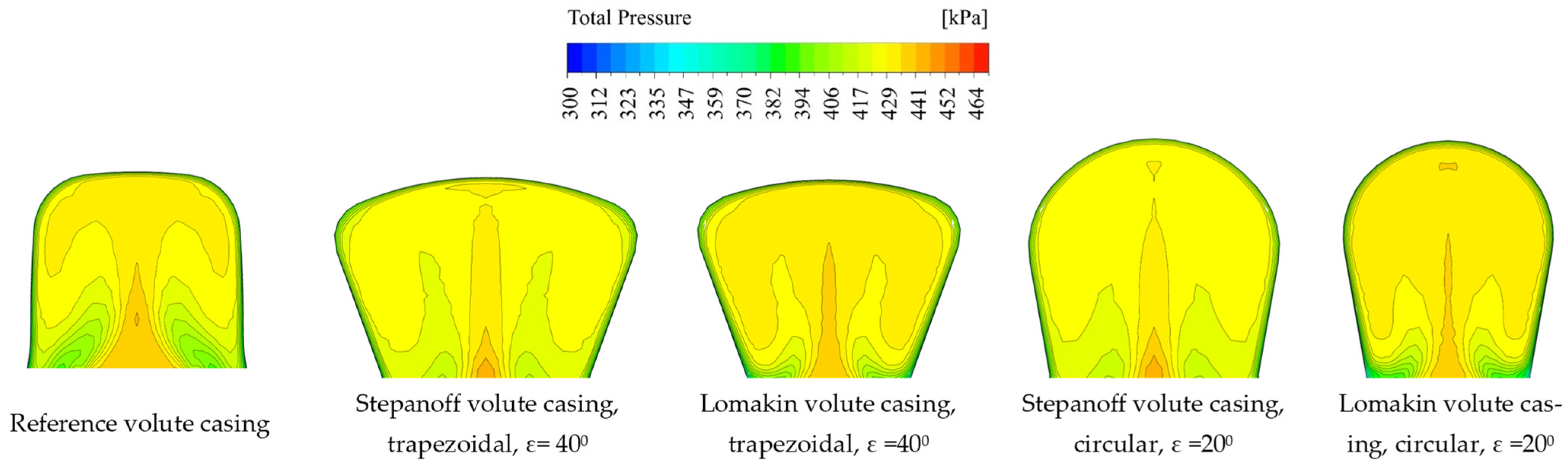
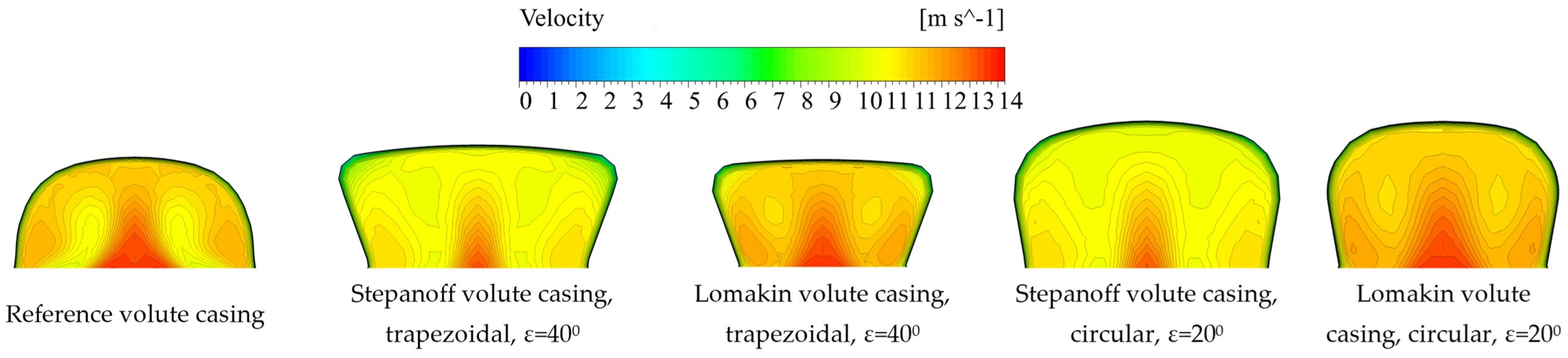
3.2. Influence of the Geometric Parameters of the Volute Casing
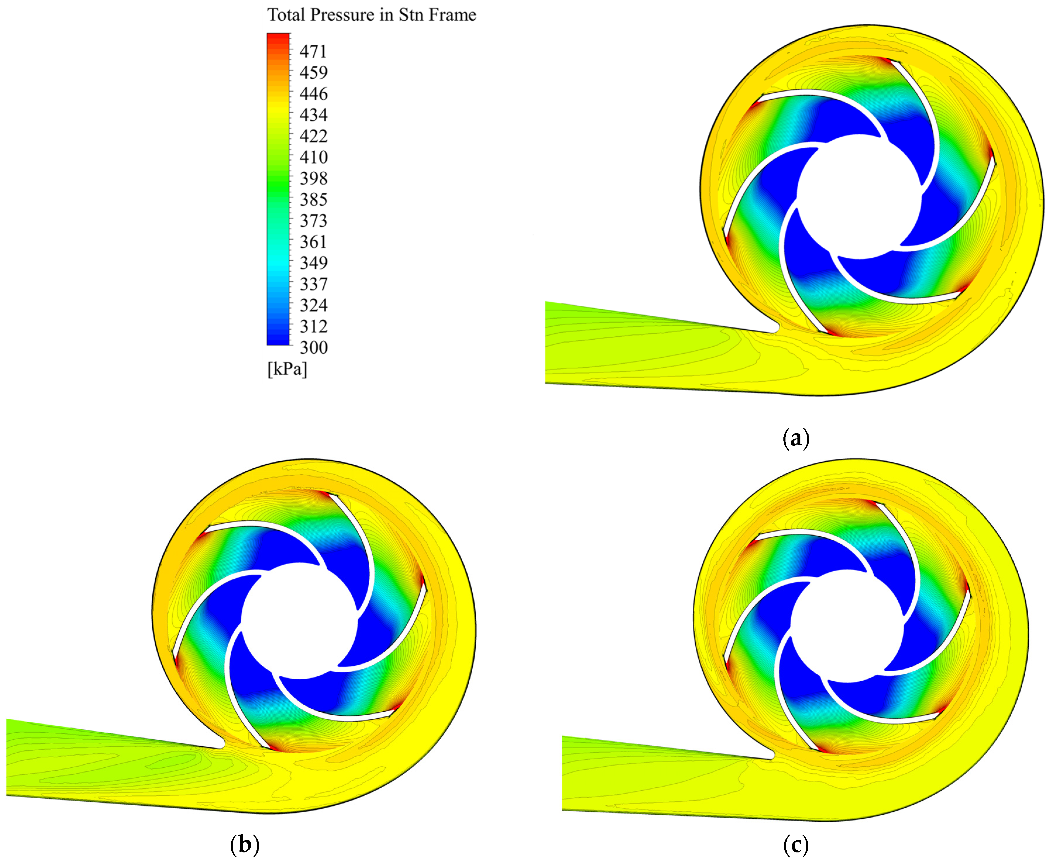
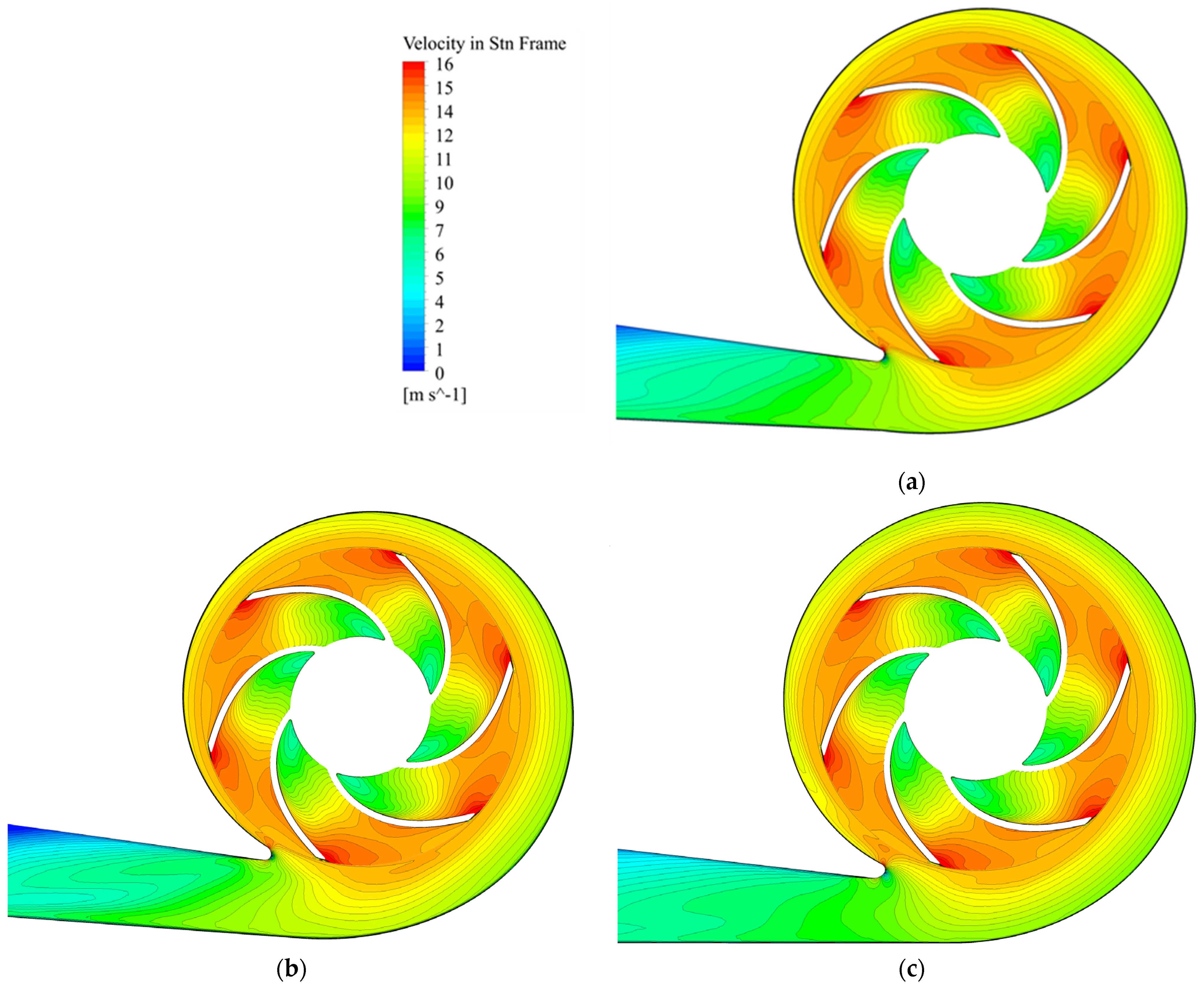
The conducted studies showed a small influence of the geometric parameters on the pump head. Changing the opening angle of the walls with a trapezoidal or circular cross-sectional shape of the volute casing affects the pump’s head by less than 1% at a flow rate other than 1.0Qopt. With 1.0Qopt, the changes are not noticeable. The change in the shape of the cross-section did not show major differences between the volute casings. This difference is approximately 1%. In contrast to the conclusions of the article by San Sheng Yang et al. [18], in this study, the volute casing with a rounded cross-section did not perform better than the other volutes.
The presented analysis shows that changing the geometric parameters does not affect the operation of the pump. Creating a volute casing that keeps a constant wall opening angle and a trapezoidal cross-section is more difficult from the point of view of keeping a constant wall thickness. Such a small impact of the geometric parameters makes it possible to choose a volute casing shape that is more convenient for processing and access by mechanical tools.

3.3. Flow Structure

The distribution of the total pressure for the 1.0Qopt in the cross-sections of the analysed volute casings is shown in Figure 9 and Figure 10. The remaining cross-sections (Figure 7b) were also analysed. Since they have very similar distributions, they are not presented in Figure 9 and Figure 10.
The difference in the total pressure distribution for volute casings designed using the conservation of angular momentum of the flow method (Lomakin volute casings) and the constant velocity method (Stepanoff volute casing) is not very clearly defined, which corresponds to small changes in the pump operating parameters. The analysis of Figure 9 and Figure 10 shows that the total pressure distribution in the Stepanoff volute casing is more uniform at the inlet to the volute casings than in the case of the Lomakin volute casing, where low pressure regions are visible at the inlet. As is known, the distribution of total pressure depends on the distribution of velocity (Figure 11 and Figure 12) near the inlet. All presented cross-sections started from an inlet diameter d3 of the volute casing and did not include space between the impeller and volute casing (see Figure 1a). The Stepanoff volute casing has a bigger d3 than the reference or Lomakin volute casing. This difference also affects the apparent distribution of the flow structure near d3.
The liquid flowing out of the impeller has a higher velocity than the liquid in the sidewall gaps and at the volute casing wall. This results in a difference in the dynamic pressure, which creates an uneven distribution of total pressure. The liquid that continues to flow in the volute casing creates characteristic vortices on both sides of the cross-section of the volute casing. This trajectory of liquid flow causes a total pressure distribution similar to an “unfolded umbrella” (Figure 9 and Figure 10). In the area of the volute casing in the spaces around the impeller, the low dynamic pressure causes an uneven distribution of the total pressure and a local increase in the velocity of the liquid near the volute casing wall and a change in the direction of flow. This complicated movement of the flow in the cross-section is directed along the volute casing and creates two side vortices that carry all the liquid out of the volute casing.
Differences in the flow structure are caused by the different widths of the volute casing inlet (sidewall gaps), the wall opening angle and the cross-sectional area of the volute casing. Perpendicular walls for the volute casing exhibit the greatest difference in the structure of the flow, as seen in the case of the reference volute casing. The Lomakin volute casing has a larger higher total pressure area at the centre of the cross-section, which is caused by the smaller cross-sectional area and correspondingly higher velocities.
A comparison of total pressure distributions in middle longitudinal cross-sections of the impeller and volute casings is shown in Figure 13. It is difficult to notice any differences in the flow structure in the impeller.
The total pressure in the volute casing around the impeller is practically uniform and similar in all pictures. The total pressure typically decreases from the inlet of the volute casing to the upper part. An unevenness of pressure is observed in the area of the volute casing from the tongue to the Pl 90 cross-section, from the tongue to the Pl 360 cross-section (for the schematic placement of this cross-section, see Figure 7b) and in the diffuser. In the first case, the Lomakin volute casing has a stable total pressure compared to the significant changes in the Stepanoff. In the second case, the difference is not so big, but the distribution and sizes of zones with the same values are different. The non-uniformity of the flow in these segments of the volute casing occurs due to the different heights of the cross-sections. Since the heights of the cross-sections were different, it was not possible to maintain the exact same height of the tongue in all volute casings.
The absolute velocity distribution in the impeller is similar and uniform for pumps with all volute casings. The velocity typically decreases from the inlet of the volute casing to the upper part (Figure 14). There are differences in the same place as in Figure 13 caused by different heights and of course different areas of cross-sections in the volute casing. The growth rate of the area from intersection Pl 45 to Pl 360 depends on the design method.

4. Conclusions

This article presents and discusses a comparison of design methods and the influence of the geometric parameters of the volute casing of a double-entry pump on its operating parameters and flow structure in the volute casing.
The volute casings were designed according to the method of conservation of angular momentum of the flow (Lomakin) and the constant velocity method (Stepanoff). The study of volute casings included changing the opening angle of the walls (20, 30 and 40 degrees) and the shape of the cross-section (circular and trapezoid). Based on the analysis of the obtained research results, the following conclusions were formulated:
  • The constant velocity method (Stepanoff volute casing) gives a flatter head–capacity curve shape of the pump characteristics than the method of conservation of angular momentum of the flow (Lomakin volute casing). The pump with the Lomakin volute casing has a steep Q-H curve and efficiency curve.
  • The pump efficiency difference between volute casings is less than 1% at 1.0Qopt. The BEP for the pump with Lomakin volute casings is at the design point. In the case of Stepanoff volute casings, the BEP is shifted towards a higher flow rate (1.2Qopt). There is also a larger pump operating range with the highest efficiency (from 1.0Qopt to 1.5Qopt) than in the case with Lomakin volute casings (from 1.0Qopt to 1.2Qopt).
  • The design method of the volute casing has the greatest impact on hydraulic losses. The difference in losses between the Stepanoff and Lomakin volute casings at 1.0Qopt is 15%. The smaller cross-sectional area of the Lomakin volute casings causes smaller hydraulic losses at 1.0Qopt than the Stepanoff volute casings, while from 1.2Qopt, the losses are greater. In the case of Stepanoff volute casings, the reference point of least losses (1.63 m) is shifted to the right about the optimal flow rate.
The disadvantage of a smaller cross-sectional area is that the optimal operating range is narrow, and the head and efficiency curves of the pump are steep.
As the flow rate decreases, the losses due to swirling flow increase. At overload, friction losses suddenly increase.
4.
Design methods have no significant effect on the head in the recommended operation range. The difference between the pumps with various volute casings is less than 1% at 1.0Qopt. The difference increases with the increase in flow rate and reaches 6% at point 1.5Qopt (Table 3).
5.
Changing the geometric parameters such as the cross-sectional shape and wall opening angle did not have a significant impact on the pump’s operating parameters.
6.
The fluid flow presented in the longitudinal cross-section does not show significant differences in the flow structure for volute casings. Small differences are observed in the area of the tongue and in the diffuser. They depend on the different heights of the cross-sections of the volute.
7.
For the researched double-entry centrifugal pump, the volute casing designed according to the method of constant velocity works most efficiently. A pump with such a volute casing has a wider range of work with high efficiency, which is needed in the process of operation.
8.
The investigated change in the volute casing parameters has practically no effect on the impeller for the investigated pump.
Based on the presented analysis, we can conclude that when designing a volute casing, the choice of method is important. The geometric parameters of the cross-section should be oriented towards matching other pump components, minimising the material, the ease of production of castings and the possibility of their further processing.
The recommendations given in the article are typical for a pump with a low-specific speed. Further research on pumps with high- and middle-specific speed characteristics is necessary.

Author Contributions

Conceptualisation, A.C. and O.M.; methodology, A.C. and O.M.; validation, A.C. and O.M.; investigation, A.C. and O.M.; data curation, A.C.; writing—original draft preparation, A.C.; writing—review and editing, O.M. and P.S.; visualisation, A.C.; supervision, O.M. and P.S.; project administration, P.S. All authors have read and agreed to the published version of the manuscript.

Funding

This research received no external funding. The calculations were performed using resources provided by the Wroclaw Centre for Networking and Supercomputing (http://wcss.pl, accessed on 1 July 2024), grant 444.

Data Availability Statement

The original contributions presented in the study are included in the article. Further inquiries can be directed to the corresponding author.

Conflicts of Interest

The authors declare no conflicts of interest.

References

  1. Gülich, J.F. Centrifugal Pumps; Springer: Berlin/Heidelberg, Germany, 2014; ISBN 978-3-642-40113-8. [Google Scholar]
  2. Lomakin, A. Tsentrobezhnyye i Osevyye Nasosy; Mashinostroyeniye: Saint Petersburg, Russia, 1965. [Google Scholar]
  3. Stepanoff, A.J. Centrifugal and Axial Flow Pumps: Theory, Design and Application; Wiley: Hoboken, NJ, USA, 1957; ISBN 978-0-471-82137-3. [Google Scholar]
  4. Aizenstein, M. Tsentrobezhnyye Nasosy Dlya Neftyanoy Promyshlennosti; Gostoptekhizdat: Moscow, Russia, 1957. [Google Scholar]
  5. Lobanoff, V.S.; Ross, R.R. Centrifugal Pumps: Design and Application, 2nd ed.; Gulf Publishing Company: Houston, TX, USA, 1992; ISBN 0-87201-200-X. [Google Scholar]
  6. Pfleiderer, C.; Petermann, H. Strömungsmaschinen, 7th ed.; Springer: Berlin/Heidelberg, Germany, 2005. [Google Scholar]
  7. Polotskiy, I.; Bognitskaya, F.; Agulnik, R. Raschet Otvodyashchikh Ustroystv Tsentrobezhnogo Nasosa; Rudnev, S., Ed.; PMB CINTIhimneftemash: Moscow, Russia, 1967. [Google Scholar]
  8. Mashin, A. Raschet i Proyektirovaniye Spiral’nogo Otvoda; Moskovskiy Energeticheskiy Institut: Moscow, Russia, 1980. [Google Scholar]
  9. Spiridonov, E.; Prokhasko, L. Raschet i Proyektirovaniye Tsentrobezhnykh Nasosov; YUUrGU: Chelyabinsk, Russia, 2004; ISBN 5-696-02887-X. [Google Scholar]
  10. Mihajlow, A.; Maliushenko, V. Konstruktsiya i Raschet Tsenrobezhnikh Ustroystv Vysokogo Davleniya; Maszinostroienie: Moscow, Russia, 1971. [Google Scholar]
  11. Son, C.H.; Jin, H.B.; Kim, M.J.; Chung, W.J. Spiral Casing of a Volute Centrifugal Pump. J. Mech. Sci. Technol. 2014, 28, 2697–2706. [Google Scholar] [CrossRef]
  12. Tao, Y.; Yuan, S.; Liu, J.; Zhang, F. Influence of Cross-Sectional Flow Area of Annular Volute Casing on Transient Characteristics of Ceramic Centrifugal Pump. Chin. J. Mech. Eng. 2019, 32, 4. [Google Scholar] [CrossRef]
  13. Baloni, B.D.; Channiwala, S.A.; Mayavanshi, V.K. Pressure Recovery and Loss Coefficient Variations in the Two Different Centrifugal Blower Volute Designs. Appl. Energy 2012, 90, 335–343. [Google Scholar] [CrossRef]
  14. Gou, Q.; Xiao, S.; Wang, T.; Yan, J. Analysis and Comparison of Two Kinds of Design Approaches for Volutes of Centrifugal Pump. Energies 2023, 16, 6128. [Google Scholar] [CrossRef]
  15. Wang, T.; Yu, H.; Fang, Y.; Xiang, R.; Kan, N.; Yan, J. A New Design for Energy-Saving Volutes in Centrifugal Pumps. Phys. Fluids 2022, 34, 115119. [Google Scholar] [CrossRef]
  16. Khan, M.F.; Gjernes, T.; Guenther, N.; Hickey, J.-P. Impact of Volute Throat Area and Gap Width on the Hydraulic Performance of Low-Specific-Speed Centrifugal Pump. Modelling 2024, 5, 659–672. [Google Scholar] [CrossRef]
  17. KIM, J.-H.; Oh, K.; Pyun, K.; Kim, C.-K.; Choi, Y.-S.; Yoon, J.-Y. Design Optimization of a Centrifugal Pump Impeller and Volute Using Computational Fluid Dynamics. IOP Conf. Ser. Earth Environ. Sci. 2012, 15, 2025. [Google Scholar] [CrossRef]
  18. Yang, S.; Kong, F.; Chen, B. Research on Pump Volute Design Method Using CFD. Int. J. Rotating Mach. 2011, 2011, 137860. [Google Scholar] [CrossRef]
  19. Ji, C.; Wang, Y.; Yao, L. Numerical Analysis and Optimization of the Volute in a Centrifugal Compressor. In Proceedings of the Challenges of Power Engineering and Environment; Cen, K., Chi, Y., Wang, F., Eds.; Springer: Berlin/Heidelberg, Germany, 2007; pp. 1352–1356. [Google Scholar]
  20. Ji, C.; Wang, Y. The Design and Flow Simulation of the Volute Casing of a Mixed Flow Pump. In Proceedings of the 2011 International Conference on Electronic & Mechanical Engineering and Information Technology, Harbin, China, 12–14 August 2011; Volume 2, pp. 820–823. [Google Scholar]
  21. Chen, Z.; Nguyen, V.T.T.; Tran, N.T. Optimum Design of the Volute Tongue Shape of a Low Specific Speed Centrifugal Pump. J. Electr. Electron Syst. 2017, 6, 2332-0796. [Google Scholar] [CrossRef]
  22. Golbabaei Asl, M.; Torabi, R.; Nourbakhsh, S.A. Experimental and FEM Failure Analysis and Optimization of a Centrifugal-Pump Volute Casing. Eng. Fail. Anal. 2009, 16, 1996–2003. [Google Scholar] [CrossRef]
  23. Zhang, Y.-L.; Li, J.-F.; Wang, T.; Xiao, J.-J.; Jia, X.-Q.; Zhang, L. Pressure Distribution on the Inner Wall of the Volute Casing of a Centrifugal Pump. Sci. Technol. Nucl. Install. 2022, 2022, 3563459. [Google Scholar] [CrossRef]
  24. Jia, X.; Li, Y.; Zhang, J.; Yan, C.; Lin, Z.; Zhu, Z. Research on the Effects of Volute Area Ratios on Centrifugal Pump Internal Flow and Noise. Phys. Fluids 2024, 36, 075111. [Google Scholar] [CrossRef]
  25. Han, Z.; Yang, S.; Chen, J.; Wang, W. Research on the Effect of Various Tongue Types on Large Volute Pumps. J. Phys. Conf. Ser. 2024, 2707, 012031. [Google Scholar] [CrossRef]
  26. Dong, R.; Chu, S.; Katz, J. Effect of Modification to Tongue and Impeller Geometry on Unsteady Flow, Pressure Fluctuations, and Noise in a Centrifugal Pump. J. Turbomach. 1997, 119, 506–515. [Google Scholar] [CrossRef]
  27. Baun, D.O.; Köstner, L.; Flack, R.D. Effect of Relative Impeller-to-Volute Position on Hydraulic Efficiency and Static Radial Force Distribution in a Circular Volute Centrifugal Pump. J. Fluids Eng. 2000, 122, 598–605. [Google Scholar] [CrossRef]
  28. Li, X.; Zhu, Z.; Li, Y.; Chen, X. Experimental and Numerical Investigations of Head-Flow Curve Instability of a Single-Stage Centrifugal Pump with Volute Casing. Proc. Inst. Mech. Eng. Part A J. Power Energy 2016, 230, 633–647. [Google Scholar] [CrossRef]
  29. Tan, L.; Zhang, D.; Shi, W.; Zhou, L.; Cai, X. Influence of Volute Basic Circle Diameter on the Pressure Fluctuations and Flow Noise of a Low Specific Speed Sewage Pump. J. Vibroeng. 2017, 19, 3779–3796. [Google Scholar] [CrossRef]
  30. Chernobrova, A.; Sotnyk, M.; Moloshnyi, O.; Antonenko, S.; Boiko, V. Influence of Different Volute Casings Theoretical Methods Design on Pump Working Processes. J. Phys. Conf. Ser. 2021, 1741, 12014. [Google Scholar] [CrossRef]
  31. Rong, L.; Böhle, M.; Yandong, G. Improving the Hydraulic Performance of a High-Speed Submersible Axial Flow Pump Based on CFD Technology. Int. J. Fluid Eng. 2024, 1, 013902. [Google Scholar] [CrossRef]
  32. Chen, B.; Li, X.; Zhu, Z. Investigations of Energy Distribution and Loss Characterization in a Centrifugal Impeller through PIV Experiment. Ocean Eng. 2022, 247, 110773. [Google Scholar] [CrossRef]
  33. International Organization for Standardization. ISO 9906 Rotodynamic Pumps—Hydraulic Performance Acceptance Tests—Grades 1, 2 and 3, 2nd ed.; ISO: Geneva, Switzerland, 2012. [Google Scholar]
Figure 1. (a) Placement of the investigated geometric parameters of the volute casings; example view (b) circular and (c) trapezoidal shape of the cross-section of the volute casings.
Energies 17 04590 g001
Figure 2. The double-entry pump experimental stand: 1—tank; 2, 11—valve; 3—inlet pipe; 4, 9—electromagnetic flowmeter; 5—double-entry pump; 6—couplings, torque meter and photo/contact tachometer; 7—electrical engine; 8—pressure sensors; 10—manometers and electronic pressure transmitters with display; 12—specially created recording module.
Energies 17 04590 g002
Figure 3. (a) Example mesh; (b) Computational model of the pump.
Energies 17 04590 g003
Figure 4. Mesh independent test.
Energies 17 04590 g004
Figure 5. Comparative characteristics of experiment and numerical simulation (CFD) results: head and efficiency curves.
Energies 17 04590 g005
Figure 6. Head and efficiency with the volute casing: reference, Stepanoff and Lomakin of (a) pump; (b) impeller.
Energies 17 04590 g006
Figure 7. (a) Cross-sectional area changes in volute casings; (b) Cross-sections of the volute casing used for flow analysis.
Energies 17 04590 g007
Figure 8. Comparative characteristics of losses in impeller and Stepanoff, Lomakin and reference volute casings.
Energies 17 04590 g008
Figure 9. Comparison of total pressure distributions in Pl360 cross-sections for reference, Stepanoff and Lomakin volute casings with flow rate 1.0Qopt.
Energies 17 04590 g009
Figure 10. Comparison of total pressure distributions in Pl 180 cross-sections for reference, Stepanoff and Lomakin volute casings with flow rate 1.0Qopt.
Energies 17 04590 g010
Figure 11. Comparison of absolute velocity distributions in Pl360 cross-sections for reference, Stepanoff and Lomakin volute casings with flow rate 1.0Qopt.
Energies 17 04590 g011
Figure 12. Comparison of absolute velocity distributions in Pl180 cross-sections of volute casings with flow rate 1.0Qopt.
Energies 17 04590 g012
Figure 13. Comparison of total pressure distributions in middle longitudinal cross-sections with flow rate 1.0Qopt for (a) reference volute casing; (b) Lomakin volute casing (trapezoidal, ε = 40°); (c) Stepanoff volute casing (circular, ε = 20°).
Energies 17 04590 g013
Figure 14. Comparison of absolute velocity distributions in middle longitudinal cross-sections with flow rate 1.0Qopt for (a) reference volute casing; (b) Lomakin volute casing (trapezoidal, ε = 40°); (c) Stepanoff volute casing (circular, ε = 20°).
Energies 17 04590 g014
Table 1. Geometric parameters of volute casings.
ParameterReference
Volute Casing
Lomakin
Volute Casing
Stepanoff
Volute Casing
MethodDoes not correspond to any methodConservation of angular momentum of the flowConstant velocity
Inlet width (b3)60 mm40 mm
b 3 = b 2 + 0.05 · d 2
52 mm
b 3 = 2 · b 2
Inlet diameter (d3)276 mm281 mm
d 3 = 1.033 1.05 · d 2
297 mm
d 3 = ( ρ + 1 ) · d 2
Cross-sectional shapeRectangularTrapezoidal and circularTrapezoidal and circular
Opening angle of the walls (ε)020°, 30°, 40°20°, 30°, 40°
where d2—diameter of the impeller outlet, b2—width of the impeller outlet, ρ —coefficient determining the diameter d3 [3].
Table 2. Main characteristics of the laboratory measurement equipment.
Sensor TypeMeasured QuantityRangeAccuracy
Electromagnetic flowmeterFlow rate8.5–283±0.5%
Electromagnetic flowmeterFlow rate19–636±0.5%
Electronic pressure transmitters with displayPressure0–1 MPa±0.05%
Electronic pressure transmitters with displayPressure0–0.2 MPa±0.05%
ThermometerTemperature0–60 °C±1%
Torque meterTorque on the shaft0–100 Nm±0.5%
Photo/contact tachometerSpeed rotation5–100,000 rpm±0.05%
Frequency converter with wattmeterElectrical power0–100 A,
380–460 V
±3.0%
Table 3. Geometric parameters of volute casings at 1.0Qopt.
ShapeεEfficiency, %Head, mLosses, mShapeεEfficiency, %Head, mLosses, m
Lomakin volute casingStepanoff volute casing
Circular20°80.1524.641.60Circular20°80.0824.702.00
Trapez.20°80.0524.641.60Trapez.20°80.0724.712.05
Circular30°79.9724.671.62Circular30°80.1224.601.96
Trapez.30°79.8524.601.65Trapez.30°79.9324.542.04
Circular40°80.1424.721.58Circular40°80.0224.561.95
Trapez.40°80.0324.681.65Trapez.40°79.8524.522.02
Table 4. Comparison of volute casings and pump operating parameters.
ParameterReference
Volute Casing
Stepanoff
Volute Casing
Lomakin
Volute Casing
Pump efficiency at 1.0Qopt80.5%80%80%
The point of highest
efficiency at appropriate flow rate
81% at 1.2Qopt81% at 1.2Qopt80% at 1.0Qopt
Pump operating range
with the highest efficiency
1.0Qopt–1.4Qopt1.0Qopt–1.5Qopt1.0Qopt–1.2Qopt
Hydraulic losses in the volute casing at 1.0Qopt1.94 m2.0 m1.7 m
Value of least loss at appropriate flow rate1.63 m at 1.3Qopt1.63 m at 1.5Qopt1.7 m at 1.0Qopt
Hydraulic losses in the impeller working with different volute casings at 1.0Qopt3.66 m3.87 m4.12 m
Value of least loss at appropriate flow rate3.0 m at 1.45Qopt3.0 m at 1.45Qopt3.1 m at 1.45Qopt
Head at 1.0Qopt24.68 m24.70 m24.50 m
Disclaimer/Publisher’s Note: The statements, opinions and data contained in all publications are solely those of the individual author(s) and contributor(s) and not of MDPI and/or the editor(s). MDPI and/or the editor(s) disclaim responsibility for any injury to people or property resulting from any ideas, methods, instructions or products referred to in the content.

