Article

Investigation of the Arc Characteristics in a Nozzle with C4F7N/CO2 Mixtures

1
State Key Laboratory of Power Grid Environmental Protection, Wuhan 430074, China
2
School of Electrical Engineering, Shenyang University of Technology, Shenyang 110870, China
*
Author to whom correspondence should be addressed.
Energies 2024, 17(18), 4593; https://doi.org/10.3390/en17184593
Submission received: 13 August 2024 / Revised: 9 September 2024 / Accepted: 11 September 2024 / Published: 13 September 2024
(This article belongs to the Special Issue Energy, Electrical and Power Engineering: 3rd Edition)

Abstract

:
C4F7N is considered the most promising alternative to SF6 due to its higher liquefaction temperature, and it is generally mixed with buffering gases such as CO2 in engineering applications. This paper establishes a two-dimensional axisymmetric nozzle arc model based on magnetohydrodynamics, calculating the nozzle arc for air, SF6, and C4F7N/CO2 mixtures. The simulation model’s accuracy is validated by comparing the calculation results for air with experimental data. This study focuses on comparing and analysing the temperature distribution, arc voltage, and energy balance characteristics of the nozzle arcs for SF6 and C4F7N/CO2 mixtures. By comparing the physical properties of the two gases, the differences in their arc characteristics are explained. Finally, the influence of different C4F7N concentrations on the arc characteristics of the mixed gas is compared. The results show that the arc voltage of the C4F7N/CO2 mixtures is higher than that of the other two gases and increases asymptotically with the decrease in current. Among the three gases, the main form of arc energy dissipation is axial thermal convection, and both radial heat transfer and axial thermal convection are more significant in the C4F7N/CO2 mixtures, resulting in the lowest arc temperature, which is more conducive to arc extinguishing. This study provides an in-depth explanation of the differences in arc morphology and temperature between SF6 and C4F7N mixed gases by comparing their ρ C p and ρ h . The findings offer theoretical support for the design and optimisation of new environmentally friendly circuit breakers.

1. Introduction

Since the 1970s, various high-voltage equipment in power systems has begun using SF6 as a filling medium, significantly reducing the insulation distance and volume of electrical equipment [1,2,3]. The global warming potential (GWP) of SF6 is 23,900 times that of CO2, and it remains in the atmosphere for a long time, making it one of the greenhouse gases with restricted emissions [1,4]. Therefore, finding environmentally friendly gas-insulating media to replace SF6 has become a focus and priority of research for scholars worldwide [5,6]. The insulating performance of C4F7N gas is twice that of SF6, and its GWP is only 10% of that of SF6, garnering widespread attention from scholars at home and abroad; it is considered one of the most promising candidate gases to replace SF6 [7,8,9,10]. Due to its higher liquefaction temperature, CO2 and other buffer gases are generally mixed with it in engineering applications [11,12,13].
Since the advent of C4F7N, many scholars have conducted studies on its insulation properties. Research by Schneider Electric found that under the minimum operating temperature of −15 °C, the impulse withstand level of the C4F7N/air mixed gas is superior to that of SF6 [14]. NECHMI and others found that in a quasi-uniform electric field, a mixed gas containing 20% C4F7N at a pressure of 0.1 MPa can achieve the same dielectric strength as sulphur hexafluoride (SF6) [15]. Hopf’s experiments revealed that the insulation performance of C4F7N/CO2 under DC voltage is similar to that of SF6 [16]. C. YI and colleagues calculated the insulation performance of C4F7N/CO2 and C4F7N/N2 mixtures, and the results indicated that adding a small amount of C4F7N to CO2 can significantly improve the insulation performance of the mixed gas [17]. Y.P. Tu added N2 and CO2 buffer gases to C4F7N, comparing the effects of N2 and CO2 on DC breakdown voltage. Under the same pressure, the performance of C4F7N/CO2 was superior [18]. H. Sun’s research found that the GIL filled with 0.5 MPa of environmentally friendly C4F7N/CO2 mixtures exhibits polarity effects under operational impulse voltage, like SF6 gas, with better insulation performance under positive polarity, where the 50% breakdown voltage is significantly higher than under negative polarity [19]. Existing research results have proven that the insulation performance of C4F7N/CO2 mixtures is sufficient to replace SF6, but for gas media used in circuit breakers and other high-voltage switchgear, it must have good insulation and arc-extinguishing performance. Currently, there are few reports on the arc-extinguishing performance of C4F7N/CO2 mixtures, and studying the characteristics of the arc inside the nozzle is important for evaluating the arc-extinguishing performance of this gas.
Based on the aforementioned reasons, this paper establishes a nozzle arc simulation model based on magnetohydrodynamics to conduct a comparative analysis of the nozzle arc characteristics of air, SF6, and C4F7N/CO2 mixtures. The simulation was conducted using commercial finite element software combined with self-developed code. The accuracy of the model is verified by comparing the simulation results of air arcs with experimental data. This study focuses on comparing the arc temperature, arc voltage, and energy balance characteristics of SF6 and C4F7N/CO2 mixtures. Additionally, the temperature distribution characteristics of the arc are further explained through a comparative analysis of the physical properties of the two gases. Finally, the impact of different C4F7N concentrations on the arc characteristics of the mixed gas is examined. The findings of this study can provide guidance for the design and optimisation of environmentally friendly gas circuit breakers.

2. Mathematical Modelling of Electric Arc

2.1. Fundamental Equation Governing the System

In the nozzle arcing process, it is assumed that the arc and the surrounding gas are in a state of local thermodynamic equilibrium. Owing to the symmetrical nature of the nozzle structure, the physical process can be accurately modelled using the time-averaged Navier–Stokes (RANS) equation [20]. Table 1 provides the units of the symbols used in the formulas.
Mass conservation equation:
ρ t + · ρ V = 0
Momentum conservation equation:
t ρ V + · ρ V V = p + · τ + J × B
Energy conservation equation:
t ρ ε + · V ρ ε + p = · k T τ · V + σ E 2 q
Electromagnetic equations:
J = σ E
· σ φ = 0
E = φ
× B = μ m J
Lorentz force:
J × B = 1 μ m × B × B = B 2 2 μ m + 1 μ m · B B

2.2. Turbulence Model

In the field of fluid dynamics, the k-ε turbulence model is widely employed as a numerical simulation method to describe the motion of fluids in turbulent states. The k-ε turbulence model incorporates five constants outlined in Table 2. To make the simulation results more accurate, this paper modifies the parameters of the turbulence model, with the actual values used shown in Table 2 [21].

2.3. Radiation Model

This study employs a semi-empirical model based on the net radiation coefficient described in Reference [22] to calculate radiation losses. The model assumes that the maximum temperature, T m a x , is located along the axis of symmetry and monotonically decreases with the arc radius. It defines the region where the radial temperature ranges from 0.83 T m a x to T m a x as the core region of the arc, considering that this region only radiates energy outward without absorbing it. The radial distance from 0.83 T m a x to T m a x is defined as the radius of the core region ( R 83 ). The relationship between the net radiation loss per unit volume per unit time, q , and the net radiation coefficient is defined by Equation (9).
q e = 4 π ε p , T , R a r c
The conductive radius of the arc ( R 4 k ) is defined as the distance from the radial position where the arc temperature is 4000 K to the maximum temperature ( T m a x ). Additionally, the arc radius ( R a r c ) is defined as the average value of the core region radius ( R 83 ) and the conductive radius ( R 4 k ), as specified in Equation (10):
R a r c = R 83 + R 4 k 2
The net radiation loss of the arc core region is given by Equation (11):
Q = 0 R 83 q e 2 π r d r
Based on the experimental results from the literature [22], the region defined by the arc radius R 4 k r R 83 is considered the reabsorption zone, where radiation losses from the core region are reabsorbed, as shown in Equation (12):
q a r q 0 = 1.1 R 4 k + R 83 2 r R 4 k R 83 2
In this equation, q a represents the volumetric radiation source, and q 0 is the maximum volumetric energy source for radiation reabsorption within the range of R 83 to R 4 k , given by Equation (13):
q 0 = Q P C T A e q
In this equation, Q represents the radiative flux at the boundary of the arc core region, and P C T is the percentage of energy reabsorbed, defined as 0.8 according to the experimental results from the literature [22]. A e q denotes the equivalent area of the reabsorption zone, given by Equation (14):
A e q = R 1 R 2 1.1 R 4 k + R 83 2 r R 4 k R 83 2 2 π r d r
Throughout the entire arc region, a positive value of q indicates the flux of radiative energy loss, specifically expressed by Equation (15):
q = q e , r R 83 q a , R 83 < r R 4 k

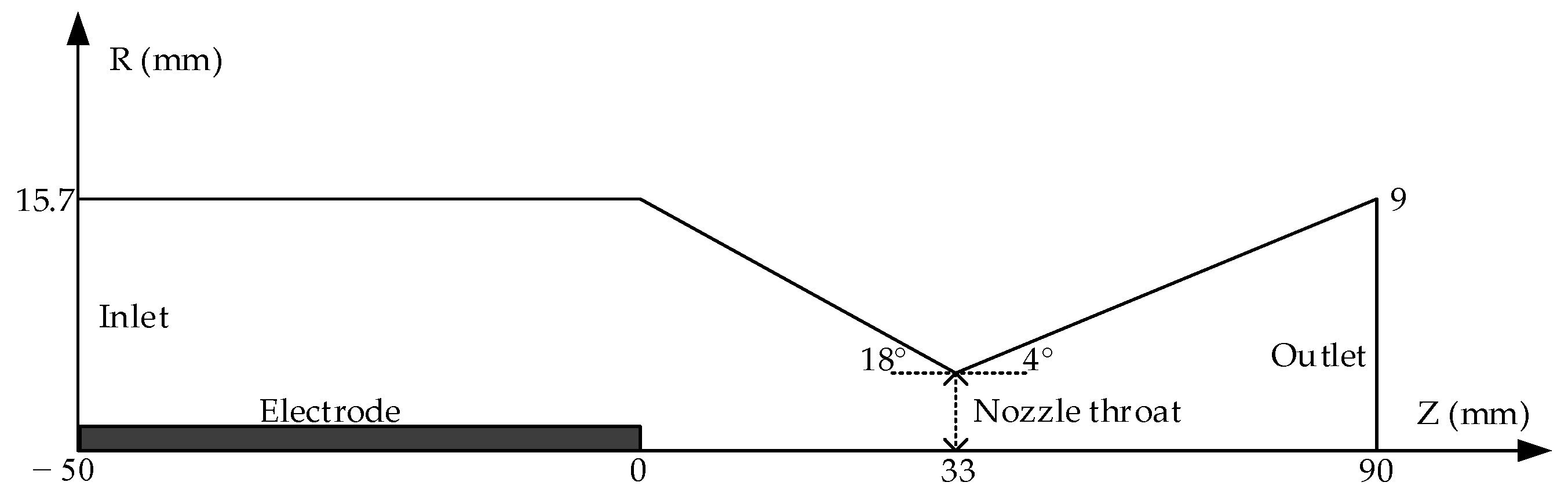
2.4. Geometric Model and Boundary Conditions

The calculation model is shown in Figure 1, which displays detailed dimensions of the nozzle structure. The arc length is 90 mm, and the downstream electrode tip is located at the nozzle exit (not shown in the figure). The upstream contact is the high-voltage contact, set as a solid, with the boundary condition set in the flux form of the current continuity equation. The downstream exit is grounded, and all other regions are gas domains.
According to the boundary conditions described in Reference [21], the upstream inlet of the nozzle is set as a pressure inlet boundary condition. The gas enters the nozzle from a pressurised tank at 10 bar stagnation pressure and 300 K stagnation temperature through an isothermal process. At the inlet, the turbulence intensity is set to 5%, and the turbulence characteristic length l is set to 0.07 times the inlet diameter. The outlet pressure is set to 1 bar to ensure that the airflow inside the nozzle is supersonic without shock waves. The turbulence boundary conditions at the outlet are set with the axial gradient of k and ϵ\epsilonϵ being zero. Other solid surfaces are set to no-slip boundary conditions, meaning the perpendicular velocity at the surface is zero, and the surfaces are set as adiabatic (i.e., no heat conduction).

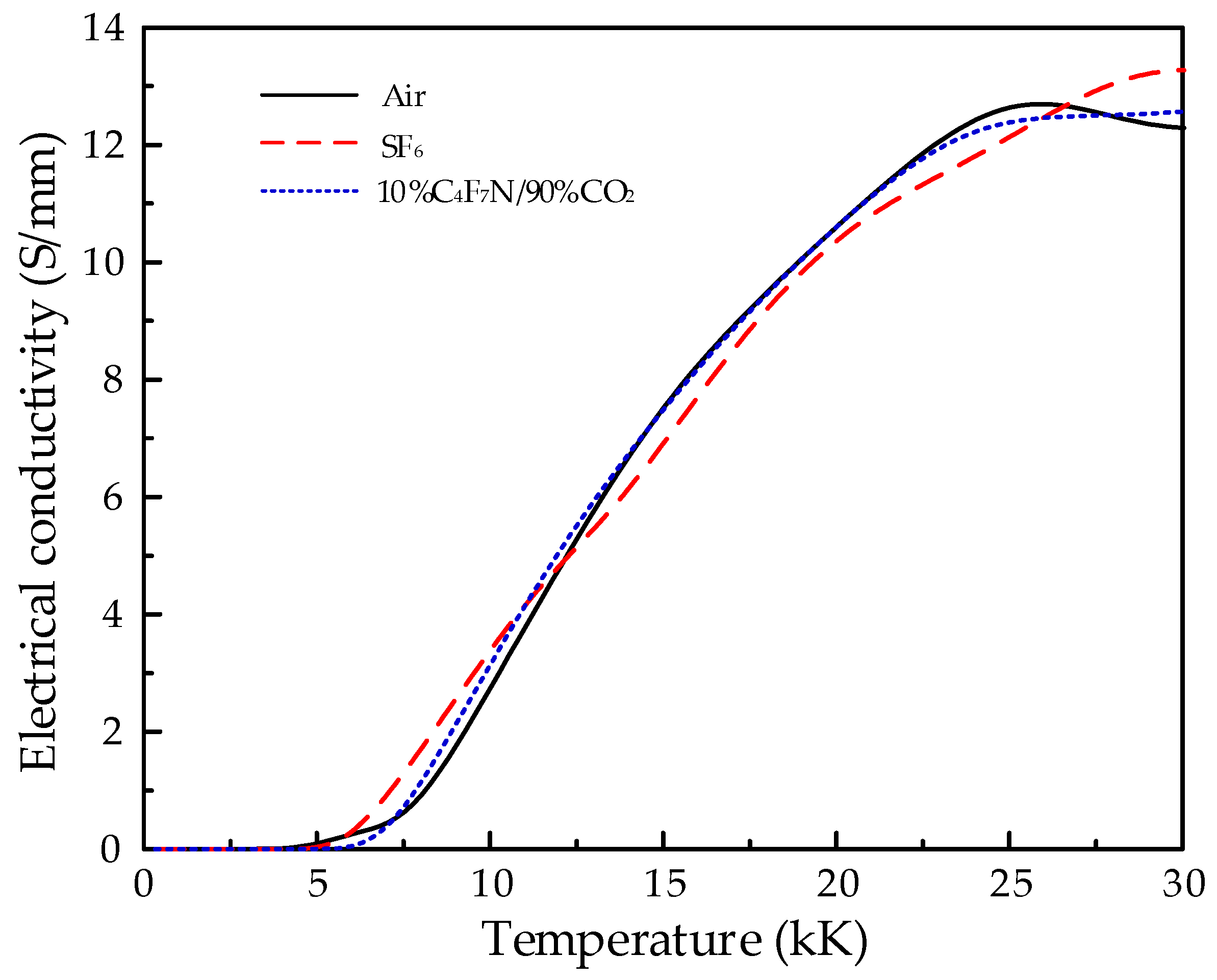
2.5. Parameters of Gas Conductivity

In establishing the arc model, the temperature dependence of gas conductivity is considered the most critical factor. Figure 2 presents the data on the conductivity of the three gases involved in this study as a function of temperature [23].

3. Comparative Study of Arc Characteristics between Environmentally Friendly Gases and SF6

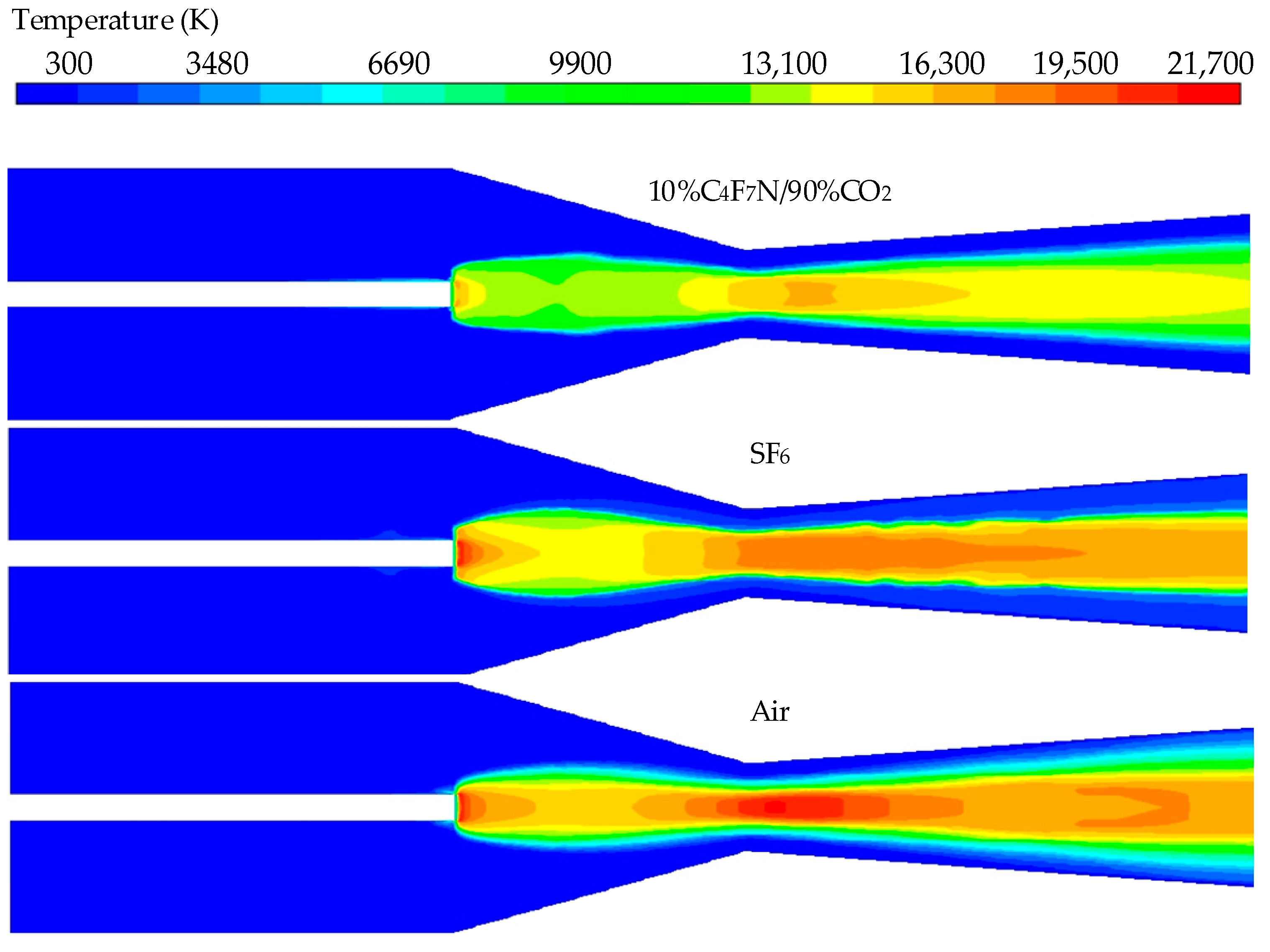
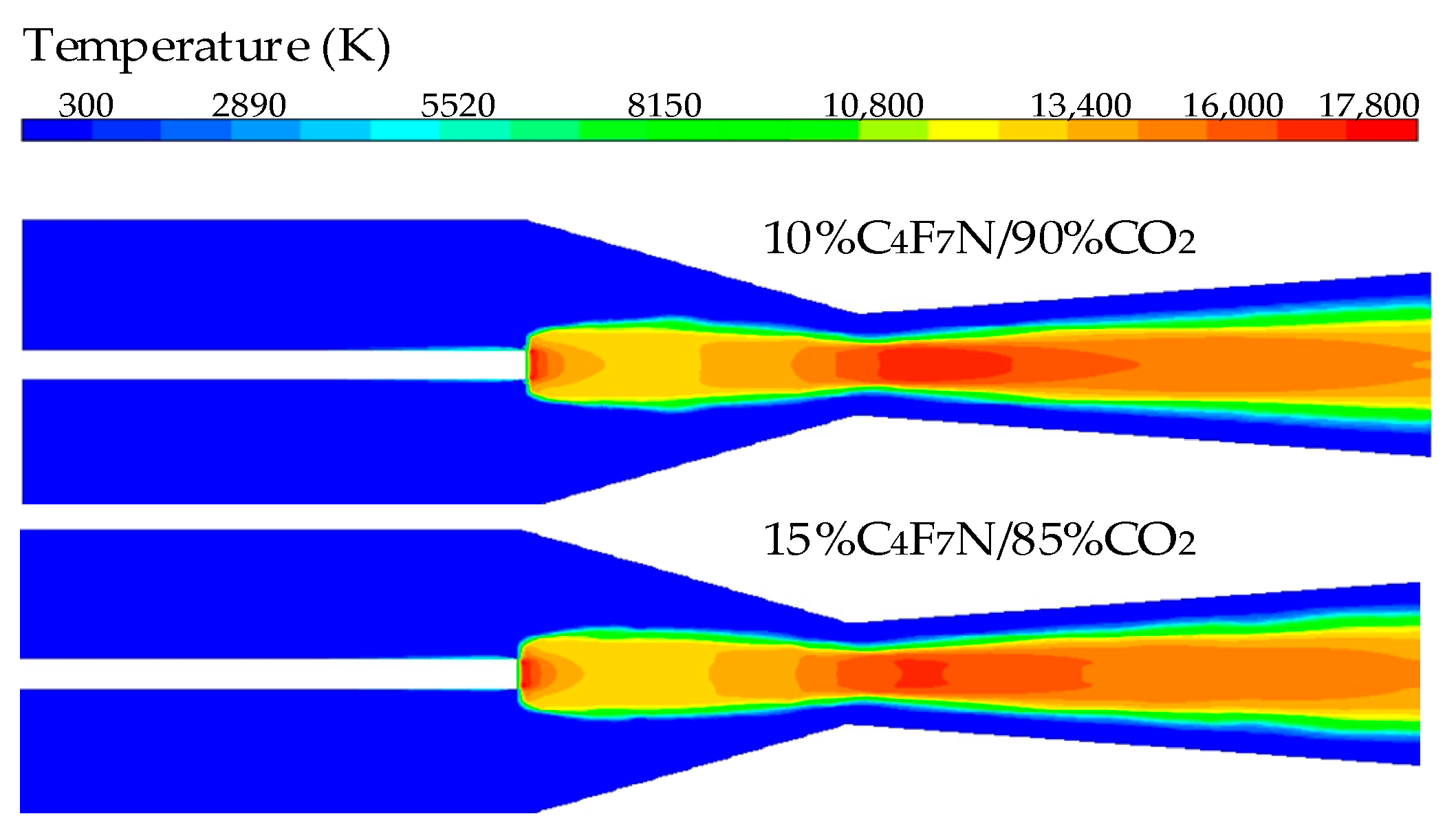
3.1. Temperature Distribution

The temperature distribution of three different media at a stagnation pressure of 10 bar and a current of 2000 A is shown in Figure 3. The high-temperature regions are concentrated near the nozzle, with the air arc temperature being relatively high. The maximum temperature of the 10%C4F7N/90%CO2 mixtures reaches 17,800 K, which is significantly lower than that of pure SF6 gas. The SF6 arc exhibits a noticeable constricted shape, while the 10%C4F7N/90%CO2 mixtures have a distinct low-temperature area near the nozzle.
Below 4000 K, the arc is essentially in an insulating state, and the position at 4000 K is defined as the arc radius, as shown in Figure 4. From Figure 4, it is evident that before the nozzle throat (shown in Figure 1), the arc radius of SF6 is noticeably larger than that of the 10%C4F7N/90%CO2 mixtures; after the throat, the arc radii of SF6 and the 10%C4F7N/90%CO2 mixtures are similar, but both are smaller than that of air. This is because, within the wide temperature range of 4000 to 15,000 K, neither SF6 nor the C4F7N/CO2 mixtures undergo decomposition reactions, thus lacking peak specific heat. As the arc radius decays from the high-temperature area to the low-temperature region, there is no bonding reaction to inhibit the temperature decay, which can significantly reduce the arc radius. Additionally, below 3000 K, SF6 and the C4F7N/CO2 mixtures have a higher thermal conductivity, which further enhances energy transfer.
To compare the temperature trends of two different gases, three typical cross-sections within the nozzle were selected under a direct current condition of 2000 A. These sections correspond to the upstream middle at z = 15 mm, the nozzle throat at z = 33 mm, and the downstream middle at z = 60 mm, as shown in Figure 1. The radial temperature distribution of the three media at these sections is depicted in Figure 5.
As depicted in Figure 5, at the three characteristic cross-sections, each of the three gas media displays a distinct high-temperature core area at the nozzle throat, where the temperature gradient is most pronounced. Moreover, the high-temperature zones upstream and downstream of the nozzle are narrower, resulting in a slower rate of arc cooling. In SF6 gas, the radial temperature distribution features a pronounced high-temperature core area. Within this area, the arc gradient is smaller. In the reabsorption zone (from the arc core area out to 4000 K), the temperature gradient is larger and the area narrower, indicating that radial energy transfer processes play a dominant role here, extinguishing the arc through radial conduction. The rate of radial temperature decrease in the 10%C4F7N/90%CO2 mixtures is significantly greater than that in the other two gases, indicating that the radial energy transfer in the 10%C4F7N/90%CO2 mixtures is more significant and more conducive to arc quenching.

3.2. Arc Voltage

Using three types of gases, the arc voltage of the nozzle was calculated by solving the magnetohydrodynamics equations, and the arc voltage from 250 to 3000 A is shown in Figure 6. Compared with the experimental results of air media in the literature [24], the calculated arc voltages for all three media exhibit a monotonically decreasing trend. For air as the gas medium, due to the selection of turbulence parameters, when the current is less than 1500 A, the calculated arc voltage is lower than the experimental values; when the current reaches or exceeds 1500 A, the calculated arc voltage approximates the experimental values, with differences fully within the experimental error range. The calculated arc voltage in SF6 is noticeably lower than that of the other two gases, and the voltage changes little when the current ranges from 500 to 1500 A. The arc voltage of the 10%C4F7N/90%CO2 mixtures is higher than the other two gases and changes more gradually as the current decreases.
Table 3 summarises the basic arc characteristics of SF6 and C4F7N mixed gases at a current of 2000A. A comprehensive comparison reveals that the arc temperature of C4F7N mixed gases is lower than that of SF6, which also leads to the arc voltage of C4F7N mixed gases being higher than that of SF6.

3.3. Energy Balance

The energy transfer process within an arc significantly impacts its temperature distribution. To investigate the effect of energy transfer on arc temperature and guide the research for SF6 alternative gases, it is necessary to analyse the principal energy transfer processes within the arc region. The energy input is Joule heating, with a substantial proportion of energy being transferred through radiation, radial heat conduction, axial heat convection, and radial heat convection. Therefore, an analysis of these four forms of energy transfer is essential. The energy balance for three gases at 2000 A is presented in Table 4, where positive values represent input and negative values represent losses.
As indicated by Table 4, the proportions of radiation losses and radial heat conduction are similar between the 10%C4F7N/90%CO2 mixtures and SF6. In the entire arc region, the proportion of radiation losses is relatively low, having a minimal impact on arc cooling. This is because only a small portion of the energy radiated from the arc core is lost through radiation, while the majority is reabsorbed. During the arc extinction process, radial heat conduction and axial heat convection play major roles. This is attributed to the presence of supersonic flow within the nozzle, where the airflow can carry heat away from the outlet, and a distinct cold flow area forms at the throat, which helps rapidly reduce the radial temperature of the arc. Radial heat conduction in the 10%C4F7N/90%CO2 mixtures is higher than that in SF6, which also explains why the temperature decrease at the arc’s edge is faster in the 10%C4F7N/90%CO2 mixtures.
For SF6, the main energy dissipation process is axial heat convection, with 62% of the energy lost through axial heat convection. The 10%C4F7N/90%CO2 mixtures exhibit a stronger axial convection effect, with 81% of the temperature lost through axial heat convection, which is also why the temperature at the outlet is lower for the 10%C4F7N/90%CO2 mixtures compared to SF6. The radial convection of the 10%C4F7N/90%CO2 mixtures is significantly higher than that of SF6.

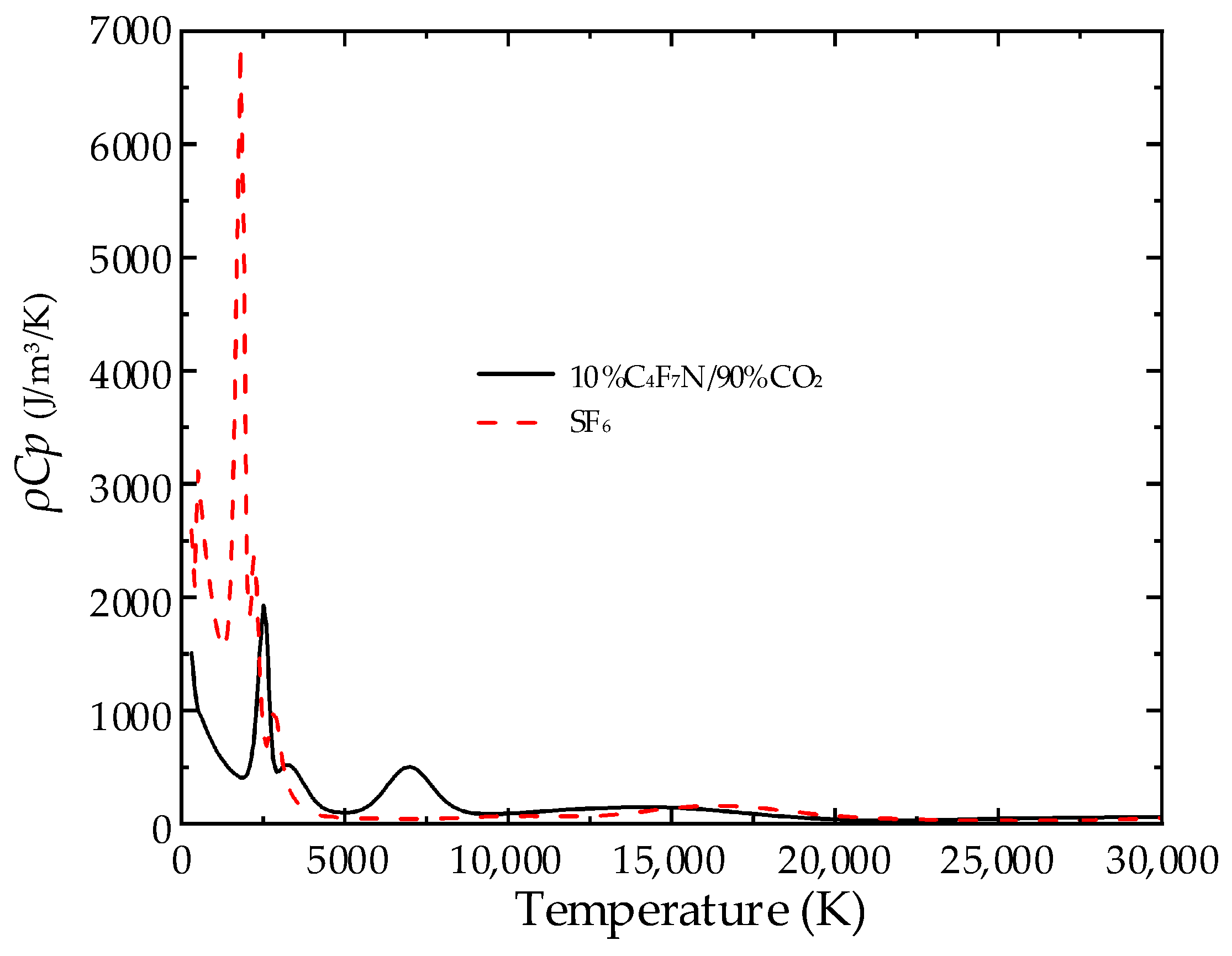
3.4. Analysis of Gas Physical Properties

The physical properties and radiation coefficients of the gas medium collectively determine the discharge characteristics of high-temperature, high-pressure electric arcs. Differences in the physical properties of various media materials result in diverse arc characteristics. To further explore the differences in arc quenching performance between SF6 and the C4F7N/CO2 mixtures, this section will investigate the impact factors of arc characteristics from the perspective of gas material physical properties.
The stability of a fluid largely depends on its viscosity coefficient. The curves showing the changes in the viscosity coefficients of the two gases with temperature are presented in Figure 7.
Due to the nozzle arc resembling a free jet, its flow stability is influenced by the critical Reynolds number. Under the same pressure gradient, a lower viscosity coefficient results in a higher critical Reynolds number. As shown in Figure 6, between 5000 and 15,000 K, SF6 has a higher viscosity coefficient compared to the mixtures. Consequently, the mixtures possess a higher critical Reynolds number relative to SF6, and the effects of turbulence are also more subdued.
The enthalpy dissipation of the gas medium, i.e., the absolute heat per unit volume of substance (ρh characteristic), plays a crucial role in the energy transfer process of the arc. The curves of the product of density and enthalpy of the two gases as a function of temperature are depicted in Figure 8.
As indicated by Figure 8, near approximately 2000 K, the ρh value for SF6 reaches its peak; conversely, the mixtures display a monotonically decreasing trend. Below 2000 K, the ρh value of the mixtures is significantly higher than that of SF6. Within the 2000 to 20,000 K range, the mixtures exhibit slightly higher ρh values than SF6; however, beyond 20,000 K, the ρh values of the two media become similar. Due to SF6 having a higher density compared to the mixtures, it exhibits a slower velocity under the same pressure gradient, thereby enhancing the role of the mixture’s enthalpy dissipation in the energy transfer process.
The energy required to raise the temperature of a unit volume of gas medium by 1 K (ρCp characteristic) affects the strength of conductive heat transfer during the energy transfer process. The curves depicting the product of density and specific heat at constant pressure for the two gases as a function of temperature are illustrated in Figure 8.
From Figure 9, it can be observed that below 4000 K, the ρCp values of SF6 exhibit several peaks; when exceeding 4000 K, these values gradually decrease, with a smaller peak reappearing around 16,000 K. Similarly, the mixtures show multiple peaks below 7000 K. Beyond 7000 K, the trend in the mixtures is similar to that of SF6 beyond 5000 K, with both showing a smaller peak near 16,000 K.
Below 4000 K, the higher ρCp values enhance the cooling capability of the gas medium at the edges of the electric arc, allowing the cold airflow to rapidly remove energy from the arc’s edges. Beyond 4000 K, the lower ρCp values lead to weakened energy transfer in the core area of the arc, consequently narrowing the high-temperature region. Additionally, due to the good heat transfer properties of the SF6 arc with the environment, it recovers quickly after the current zero-crossing. Considering the significant impact of turbulence on the arc, ρCp substantially affects the radial temperature distribution and radius of the arc and directly determines the electrical conductivity.

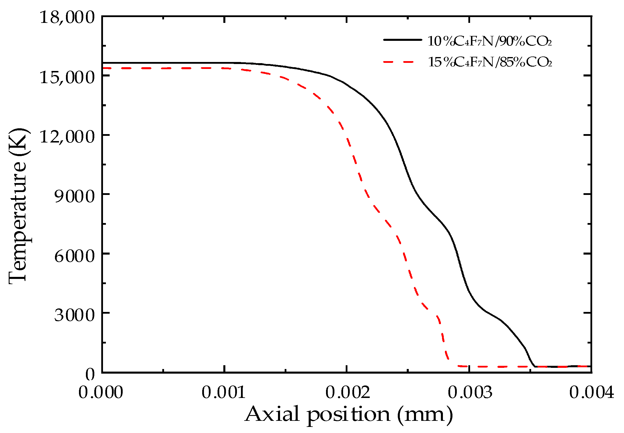
3.5. The Impact of C4F7N Content on Arc Characteristics

The temperature distribution cloud maps of the two gases at 2000 A and the radial temperature distribution at the nozzle throat are shown in Figure 10 and Figure 11 under different C4F7N contents. From Figure 10 and Figure 11, it can be seen that the arc shape remains consistent across different contents; as the C4F7N content increases, the arc temperature slightly decreases, with the 15%C4F7N/85%CO2 mixtures experiencing a faster drop in temperature and a noticeable reduction in arc radius. Therefore, the 15%C4F7N/85%CO2 mixtures have a stronger radial heat conduction capability, and increasing the C4F7N content is beneficial for arc extinction. However, as the C4F7N content increases, the GWP of the mixtures also becomes higher [25].

4. Conclusions

Based on the theory of magnetohydrodynamics, this paper uses the Prandtl mixing length model to describe turbulence and a semi-empirical model to describe radiation. Calculations were performed on the nozzle arcs of 10%C4F7N/90%CO2, SF6, and air, with a comparative analysis conducted on both arc characteristics and physical parameters. By comparing the ρ C p and ρ h of SF6 and C4F7N mixed gases, this paper uncovers the deeper reasons for the differences in their arc morphology and temperature. The results provide important theoretical support for the development and optimisation of environmentally friendly high-voltage circuit breakers, demonstrating both innovation and practical value. The results indicate the following:
  • Under the influence of gas blowing, the primary energy dissipation process of the arc is axial convection, where the axial temperature gradient of the 10%C4F7N/90%CO2 mixtures’ arc is significantly higher than that of the SF6 gas under the same blowing intensity. This indicates that the energy loss in the C4F7N mixture arc occurs more rapidly under gas blowing, making it more favourable for arc extinguishing.
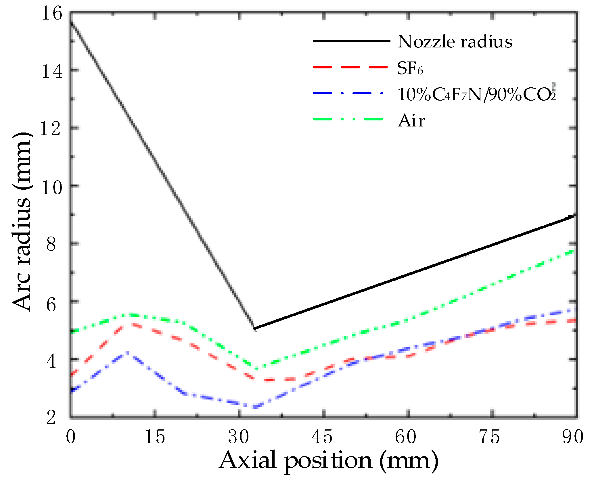
  • Through the comparison of physical parameters, it is concluded that the lower viscosity coefficient of the mixed gas results in a weaker turbulence effect compared to pure SF6 gas. The larger ρ h value of the mixed gas below 4000 K enhances the heat dissipation process at the electrical boundary, while the larger ρ C p value above 4000 K increases the arc radius, which is unfavourable for arc extinguishing.
  • The 15%C4F7N/85%CO2 mixtures exhibit stronger radial heat conduction, resulting in a lower arc temperature. Therefore, increasing the C4F7N content is beneficial for arc extinguishing.

Author Contributions

W.W.: Conceptualisation, investigation, and writing—original draft; X.Y.: Funding acquisition, writing—review and editing, and resources; X.L.: Methodology and supervision; D.G.: Software, validation, data curation, and visualisation; Z.G.: Resources, project administration, and supervision. All authors have read and agreed to the published version of the manuscript.

Funding

This research was funded by the Open Fund of the State Key Laboratory of Power Grid Environmental Protection (No. GYW51202301431).

Data Availability Statement

The original contributions presented in the study are included in the article, further inquiries can be directed to the corresponding author.

Conflicts of Interest

The authors declare no conflicts of interest.

References

  1. Simmonds, P.G.; Rigby, M.; Manning, A.J.; Park, S.; Stanley, K.M.; McCulloch, A.; Henne, S.; Graziosi, F.; Maione, M.; Arduini, J.; et al. The increasing atmospheric burden of the greenhouse gas sulfur hexafluoride (SF6). Atmos. Chem. Phys. 2020, 20, 7271–7290. [Google Scholar] [CrossRef]
  2. Xiao, A.; Owens, J.G.; Bonk, J.; Zhang, A.; Wang, C.; Tu, Y. Environmentally friendly insulating gases as SF6 alternatives for power utilities. In Proceedings of the 2019 2nd International Conference on Electrical Materials and Power Equipment (ICEMPE), Guangzhou, China, 7–10 April 2019. [Google Scholar]
  3. Owens, J.G. Greenhouse gas emission reductions through use of a sustainable alternative to SF6. In Proceedings of the 2016 IEEE Electrical Insulation Conference (EIC), Montreal, QC, Canada, 19–22 June 2016. [Google Scholar]
  4. Kovács, T.; Feng, W.; Totterdill, A.; Plane, J.; Dhomse, S.; Gómez-Martín, J.C.; Stiller, G.P.; Haenel, F.J.; Smith, C.; Forster, P.M.; et al. Determination of the atmospheric lifetime and global warming potential of sulfur hexafluoride using a three-dimensional model. Atmos. Chem. Phys. 2017, 17, 883–898. [Google Scholar] [CrossRef]
  5. Li, X.; Liu, L.; Wang, W.; Geng, Z. Analysis of breaking characteristics of C4F7N/CO2 mixture gas in circuit breaker. Energies 2024, 17, 2638. [Google Scholar] [CrossRef]
  6. Nechmi, H.E.; Michelarakis, M.; Haddad, A.; Wilson, G. Clarifications on the behavior of alternative gases to SF6 in divergent electric field distributions under AC voltage. Energies 2021, 14, 1065. [Google Scholar] [CrossRef]
  7. Kieffel, Y. Characteristics of g³—An alternative to SF6. In Proceedings of the 2016 IEEE International Conference on Dielectrics (ICD), Montpellier, France, 3–7 July 2016. [Google Scholar]
  8. Chen, L.; Zhang, B.; Li, X.; Yang, T. Decomposition pathway of C4F7N gas considering the participation of ions. J. Appl. Phys. 2018, 51, 153001. [Google Scholar] [CrossRef]
  9. Gao, W.; Posada, L.; Shiravand, V.; Shubhashish, S.; Price, C.; Zhang, B.; Potyrailo, R.; Younsi, K.; Shan, S.; Ndiaye, I.; et al. Decomposition characteristics of C4F7N-based SF6-alternative gas. IEEE Trans. Dielectr. Electr. Insul. 2018, 25, 1340–1350. [Google Scholar] [CrossRef]
  10. Andersen, M.; Kyte, M.; Andersen, S.; Steffensen, A.L.; Sørensen, S.R.; Nielsen, C.J. Environmental and insulation characteristics of C4F7N as an alternative to SF6. Environ. Sci. Technol. 2017, 51, 1321–1329. [Google Scholar]
  11. Chen, J.; Smith, A.; Johnson, P. Decomposition mechanism of C4F7N/CO2 gas mixture based on molecular dynamics. AIP Adv. 2023, 13, 024401. [Google Scholar]
  12. Miller, B.; Thompson, D.; Evans, R. Detection of decomposition products of C4F7N/CO2 gas mixture. Sci. Direct. 2022, 18, 104567. [Google Scholar]
  13. Williams, M.; Roberts, T.; Brown, H. Calculation of thermodynamic physical properties of C4F7N/CO2 mixed gas. IEEE Trans. Dielectr. Electr. Insul. 2021, 26, 1949–1955. [Google Scholar]
  14. Preve, C.; Maladen, R.; Piccoz, D. Method for validation of new eco-friendly insulating gases for medium voltage equipment. In Proceedings of the 2016 IEEE International Conference on Dielectrics (ICD), Montpellier, France, 3–7 July 2016. [Google Scholar]
  15. Nechmi, H.E.; Beroual, A.; Girodet, A.; Vinson, P. Fluoronitriles/CO2 gas mixture as promising substitute to SF6 for insulation in high voltage applications. IEEE Trans. Dielectr. Electr. Insul. 2016, 23, 2587–2593. [Google Scholar] [CrossRef]
  16. Hopf, A.; Britton, J.A.; Rossner, M.; Berger, F. Dielectric strength of SF6 substitutes, alternative insulation gases and PFC-gas-mixtures. In Proceedings of the IEEE Electrical Insulation Conference (EIC), Montreal, QC, Canada, 18–22 June 2017. [Google Scholar]
  17. Yi, C.; Yuan, Z.; Tu, Y.; Zhang, Y.; Wang, C. Measurements of discharge parameters in C3F7CN/CO2 and C3F7CN/N2 gas mixtures by SST. IEEE Trans. Dielectr. Electr. Insul. 2020, 27, 1015–1021. [Google Scholar] [CrossRef]
  18. Tu, Y.; Ai, X.; Cheng, Y.; Jin, H.; Wang, C. DC breakdown characteristics of C3F7CN/N2 gas mixtures. Trans. China Electrotech. Soc. 2018, 33, 5189–5195. [Google Scholar]
  19. Sun, H.; Zhang, C.; Shen, M.; Liu, Y.; Wang, X.; Li, J. Study on the operating impulse insulation characteristics of environmentally friendly C4F7N/CO2 gas mixtures. High Volt. Appar. 2021, 57, 90–95. [Google Scholar]
  20. Liu, J. Modelling and Simulation of Air and SF6 Switching Arcs in High Voltage Circuit Breakers. Ph.D. Thesis, University of Liverpool, Liverpool, UK, 2016. [Google Scholar]
  21. Zhang, Q. Modelling of Turbulent SF6 Switching Arcs. Ph.D. Thesis, University of Liverpool, Liverpool, UK, 2014. [Google Scholar]
  22. Yan, J.; Nuttall, K.; Fang, M. A comparative study of turbulence models for SF6 arcs in a supersonic nozzle. J. Phys. Appl. Phys. 1999, 32, 14–19. [Google Scholar] [CrossRef]
  23. Plasma Data Exchange Project. Available online: http://plasma-data.net/index (accessed on 3 August 2024).
  24. Fang, M.T.C.; Ramakrishnan, S.; Meserle, H.K. Scaling laws for gas-blast circuit-breaker arcs during the high current phase. IEEE Trans. Plasma Sci. 1980, 8, 357–362. [Google Scholar] [CrossRef]
  25. Bian, C.; He, B.; Lin, X.; Liu, Y.; Lou, H.; Kong, L.; Dai, X.; Wu, S.; Meng, F.; Liu, Y. Research on Interruption Performance of Environmentally Friendly C4F7N Mixed-Gas-Insulated Switchgear. Energies 2022, 15, 6500. [Google Scholar] [CrossRef]
Figure 1. Nozzle geometry (not to scale).
Energies 17 04593 g001
Figure 2. The conductivities of air, SF6, and 10%C4F7N/90%CO2.
Energies 17 04593 g002
Figure 3. Temperature distribution in different gases.
Energies 17 04593 g003
Figure 4. Arc radius in different gases.
Energies 17 04593 g004
Figure 5. Radial temperature distribution of the arc at a stagnation pressure of 10 bar and a DC current of 2000 A.
Energies 17 04593 g005aEnergies 17 04593 g005b
Figure 6. V-I characteristics.
Energies 17 04593 g006
Figure 7. Kinetic viscosity curves of two gases with temperature variation at 1 bar.
Energies 17 04593 g007
Figure 8. ρh characteristics of two gases with temperature.
Energies 17 04593 g008
Figure 9. ρCp characteristics of two gases with temperature variation at 1 bar.
Energies 17 04593 g009
Figure 10. Temperature distribution under different C4F7N proportions.
Energies 17 04593 g010
Figure 11. Temperature distribution of nozzle throat under different C4F7N proportions.
Energies 17 04593 g011
Table 1. Each symbol and its unit.
SymbolInterpretation and Unit
BMagnetic induction intensity (T)
EElectric field intensity (V/m)
JCurrent density (A/m2)
T Temperature (K)
V Velocity vector (m/s)
kHeat conductivity (w/(m·K))
pPressure (Pa)
q Net radiation loss per unit volume and time (w/m3)
tTime (seconds)
μmMagnetic conductivity (H/m)
ρDensity (kg/m3)
σConductivity (S/m)
τPressure tensor (Pa)
φElectric potential (V)
Table 2. Values of the five parameters in the k-ε model.
Constant ParameterValue
σk1
σε1.3
C0.09
C1.44
C2e1.92
Table 3. Basic arc characteristics of SF6 and C4F7N/CO2 mixtures at a current of 2000 A.
Gas TypeMaximum Temperature (kK)Voltage (V)Arc Radius-z = 15 mm (mm)Arc Radius-z = 33 mm (mm)Arc Radius-z = 60 mm (mm)
SF621.160053.254.1
10%C4F7N/90%CO217.87253.62.44.4
Table 4. Energy balance.
Gas TypeEnergy Input (106 W)Radiation Loss (%)Radial Heat Conduction (%)Axial Convection Heat Transfer (%)Radial Convection Heat Transfer (%)
Air1.34−11.7−25.5−74.214.5
SF61.14−12.2−29.9−73.18.5
C4F7N/CO21.44−9.72−34.9−81.218.6
Disclaimer/Publisher’s Note: The statements, opinions and data contained in all publications are solely those of the individual author(s) and contributor(s) and not of MDPI and/or the editor(s). MDPI and/or the editor(s) disclaim responsibility for any injury to people or property resulting from any ideas, methods, instructions or products referred to in the content.

