Article

Parametric Study of the Effects of a Vortex Generator on the Combustion Characteristics of Liquid Petroleum Gas and Physical Air–Fuel Flow on a Slot Burner

by
Amornrat Kaewpradap
* and
Maneeratanaporn Phoothornsri
Department of Mechanical Engineering, Faculty of Engineering, King Mongkut’s University of Technology Thonburi, Bangmod, Thungkhru, Bangkok 10140, Thailand
*
Author to whom correspondence should be addressed.
Energies 2024, 17(18), 4608; https://doi.org/10.3390/en17184608
Submission received: 29 July 2024 / Revised: 5 September 2024 / Accepted: 12 September 2024 / Published: 13 September 2024
(This article belongs to the Section I2: Energy and Combustion Science)

Abstract

:
We conducted a numerical study of the effects of a vortex generator (VG) on the combustion characteristics and physical fluid flow of LPG on a porous bluff-body slot burner (PBSB) model, validating the numerical and experimental results of the temperature distribution and mixture flow velocity. The VG position (fuel (F) and air (A) slots), direction (clockwise, CW, and counterclockwise, CCW), aspect ratio (AR), and distance (S) were investigated parametrically in our porous vortex generator slot burner (PVGSB) model. According to our results, the VGSB model with a VG angle of 60°, CW direction, aspect ratio of 0.4, and VG distance of 0 mm enhanced the flame temperature by 24.4% due to a greater vortex influence. Moreover, applying a reverse triangular bluff body to the VGSB model had a stronger effect on the vortices and swirl flow of the mixture compared to the cylindrical bluff body, achieving 34.9% higher combustion temperatures compared to the referenced PBSB model. This numerical study of using LPG combustion on a slot burner with VGs and a reverse triangular bluff body, which we refer to as the VGSB model, could be applied to enhancing physical air–fuel flow and the flame temperature as characteristics of combustion.

1. Introduction

In 2022, the demand for cooking gas, or liquefied petroleum gas (LPG), in Thailand increased by 9% compared to 2021 [1], although its cost is relatively low. Most LPG is obtained from refining crude oil and natural gas separation processes. LPG mainly consists of hydrocarbons such as propane (C3H8) and butane (C4H10) and is colorless, odorless, lighter than water, and heavier than air, in addition to being easy to ignite and having a high heating value. The flame temperature of LPG is about 1900–2000 °C, making it useful as fuel for household cooking, industrial plants, the petrochemical industry, and transportation. When used for transportation, LPG is compressed into pressurized cylinders and has specified hose safety standards [2]; additional safety standards have also been created for LPG usage in other applications, such as cooking burners and cylinders [3]. The increase in LPG consumption in the cooking, industrial, and transport sectors has been summarized by the Department of Alternative Energy Development and Efficiency [4]. Moreover, the physical and thermal properties of LPG have been studied and included in these safety investigations [5]. Generally, LPG is used for premixed, partially premixed, and non-premixed combustion because, during complete combustion (with a premixed flame or blue flame), high premixed flame length ratios were observed in premixed and partially premixed combustion scenarios due to the premixing between air and fuel. In order to improve the properties of partially premixed flames, experimental studies on the lift-off, blowout, and drop-back of LPG flames in a tubular burner were conducted [6]. Premixed flames can also be obtained from premixed and partially premixed combustion; however, the risk of flashback flames should be considered [7]. Thus, non-premixed combustion has been utilized in the industrial sector to avoid flashback flames and the risk of explosion. In parts of the industrial sector that utilize LPG combustion, slot burners can be used to provide uniform and high flame temperatures that are appropriate for the food, glass, and metal industries. They should be designed with appropriate lengths to make LPG suitable for use in various applications. In practice, slot burners have a higher heat flux than other burners.
In past research, the heat transfer characteristics of slot burners and premixed impinging flame jets have been examined [8]. Rectangular jet burners were shown to induce a more uniform heat flux than that of a ring jet, and Reynolds number effects were discussed in [9]. The nature of the flames and LPG emissions of an inverse diffusion flame (IDF) using a coaxial burner were also investigated in [10]. To improve the combustion flame of an IDF burner, a swirler was applied to obtain a more stable flame; however, the flame length of the burner without the use of a swirler became more stable due to an increase in the fuel velocity. Wider and shorter flames were observed, and the soot-free-length flame (SFLF) increased with the air velocity. The use of a swirler was shown to improve the premixing of fuel and air, making the blue zone flame longer, and the rotation effect of a 30° swirl angle was shown to promote good mixing with low CO and NOx emissions. Moreover, punched triangular vortex generators (PTVGs) and punched rectangular vortex generators (PRVGs) were utilized to control boundary layer separation in [11]. The optimal installation angle was shown to be 12° with a 3.0 mm distance between the vortex generators. Furthermore, small vortex generators reduced drag forces when installed at 50% of the chord length. Two-dimensional triangular and semicircular vortex generators were used to study the flow and turbulent heat transfer of the hybrid nanofluid DWCNT–TiO2. The results showed that the Reynolds number and volume fraction were higher due to an increase in the Nusselt number and a drop in pressure. The influence of the semicircular vortex generator resulted in a higher Nusselt number than that of the triangular generator. The efficiency of a semicircular vortex generator increased the Nusselt number at a height of 1.0 mm [12]. A numerical study of fluid flow and heat transfer in rectangular channels, such as the common-flow-down, common-flow-up, and mixed-flow directions, was performed in [13]. A delta-shaped winglet longitudinal vortex generator (LVG) was applied with air as a working fluid to predict the Nusselt numbers of smooth channels. Mixed LVGs with greater numbers of rows and larger AR values resulted in higher Nusselt numbers at every Reynolds number. However, the overall performance was reduced by installing a single row of LVGs. The common-flow-up direction and AR = 0.2 provided the best Nusselt number and overall performance. Research related to the effects of parallel serrated fin angles heat exchangers has also been conducted [14]. A serrated fin at a 60° angle gave the highest heat transfer rate and friction factor [15]. Consequently, its pressure drop was greater. This resulted in a lower efficiency than for a serrated fin, while a 90°-angle fin showed the poorest efficiency due to its low heat transfer. Although its pressure drop was smaller, it was close to a 30° fin angle. Moreover, many studies on heat transfer using VGs in the smooth tubes of air-cooled condensers showed improved thermal performance owing to the enhancement of the Reynolds number by a delta winglet pair of VGs [16,17,18]. The previous study showed that fluid flow was influenced by the vortex generator. It extended the mixing time between fuel and air and caused combustion to be more complete [19]. The EHD in wire was also studied for the enhancement of convection heat transfer [20]. In addition, flame stability and the characteristics improved by inverse diffusion flame burners [21,22,23] and bluff bodies [24,25] were previously investigated.
A slot burner was developed, as shown in the previous study; however, many problems related to the flame analysis and combustion characteristics have rarely been investigated. The current research aims to study a thermal analysis, improve combustion characteristics, and achieve higher flame temperatures using a numerical slot burner model with VGs. Following the mathematical modeling of non-premixed combustion, the direction, aspect ratio, angle, and distance between the VGs and shapes of the bluff body were varied to study the flame temperature distribution.

2. Methodology

2.1. Combustion Equation

The fuel–air chemical equations were applied to the chemical equilibrium in the desired reaction, as shown in Equation (1) [26]. Following the chemical reaction of hydrocarbons, LPG combustion was also simulated using stoichiometric combustion.
C u H v O w N x S y + u + v 4 + w 4 + y O 2 + 3.76 N 2 u CO 2 + v 2 H 2 O + y SO 2 + 3.76 u + v 4 + w 4 + y N 2

2.2. Equivalent Ratio

The equivalence ratio (Φ) is the ratio between the actual fuel–air mass flow rate and the stoichiometric fuel–air mass flow rate, as shown in Equation (2). When Φ = 1, Φ < 1, and Φ > 1, these are referred to as stoichiometric, lean, and rich mixtures, respectively.
Φ = ( fuel / air ) actual ( fuel / air ) stoichiometric

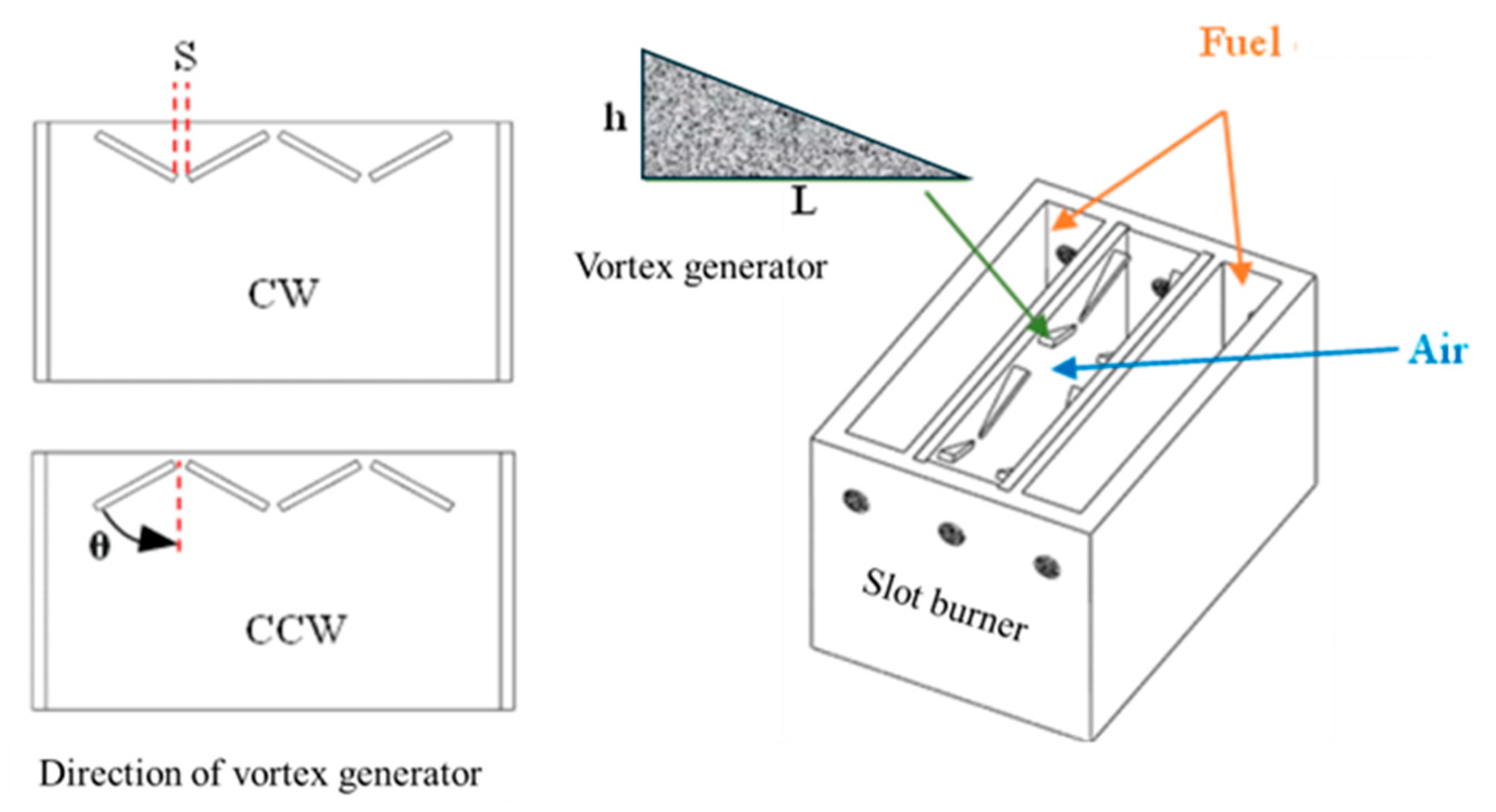
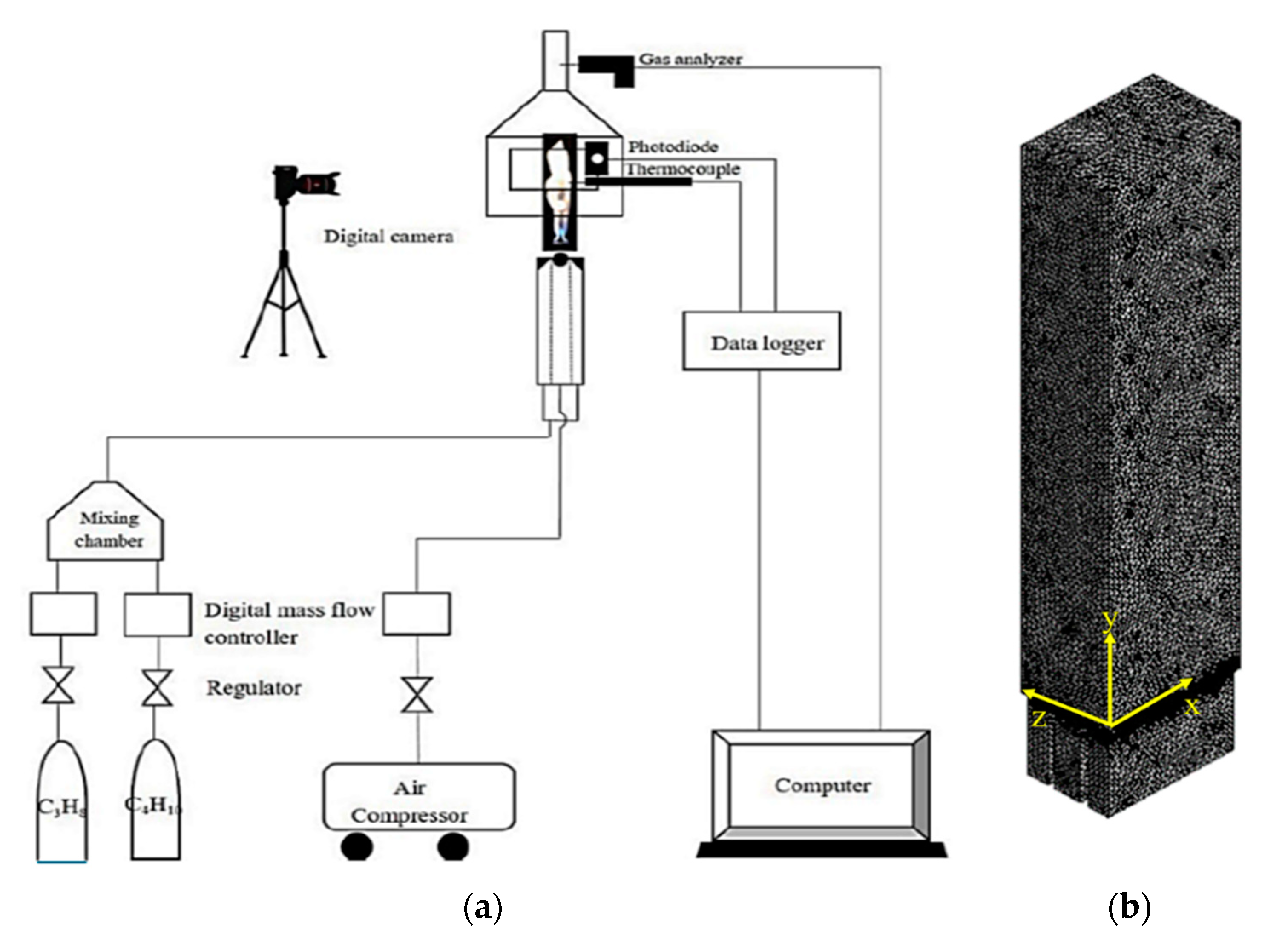
2.3. Slot Burner Model

Slot burners are widely used for industrial purposes. The burner is made from stainless steel 304, which is composed of physical (8.0 g/cm3 density) and thermal (500 J/kg K heat capacity, 16.2 W/m K thermal conductivity, and 0.44 radiation emissivity) properties. They are rectangular and possess an air outlet between two fuel outlets. The slot burner is equipped with two exit fuel slots with an 8 mm fuel slot width, 10 mm fuel slot width, and 50 mm length, as shown in Figure 1. To improve the combustion characteristics of slot burners, we combined them with porous media and bluff bodies on the previous slot burner, referred to as PSB and PBSB [25], which are presented in Figure 1. In our previous study, LPG combustion characteristics were improved by a PBSB, which was used as the reference model in this study. Flame temperatures of 845.2 K, 1298.0 K (1025 °C, referenced in [25]), and 1254.6 K were obtained on the PBSB (referenced research) at 1.5 cm, 6.0 cm, and 10.0 cm, which are lower than the adiabatic flame temperature of LPG (2000–2200 °C or 2273–2473 K). Thus, we aimed to improve the mixture flow to increase the flame temperature.
In this study, a vortex generator (VG) was combined with the referenced PBSB to study the mixture flow and flame temperature and is referred to as a porous vortex generator slot burner (PVGSB) model. Figure 2 shows the VG’s position in the PBSB model. The parameters studied were the position, angle, direction, aspect ratio (AR = h/L), and distance. Table 1 shows the computational conditions of LPG combustion on the PVGSB model with VG parameters, while the model itself is presented in Figure 3. The VG’s position between the fuel (F) and air (A) slots was varied in cases P1 and P2. VG angles of 30°, 45°, and 60° were investigated in cases P3, P2, and P4, respectively. Clockwise (CW) and counterclockwise (CCW) VG directions were applied in cases P4 and P5. In cases P5, P6, and P7, aspect ratios of 0.2, 0.3, and 0.4 were studied. Moreover, VG distance variations of 0, 1.0, and 2.0 mm were applied and compared in cases P7, P8, and P9, respectively.
In addition, the bluff body used in our previous study showed a higher velocity of air, which induced fuel flow and enhanced combustion characteristics [25]. Therefore, in this study, we added the bluff body to increase airflow velocity with the VG on the slot burner, creating PVGSB and VGSB models in which the LPG combustion characteristics and mixture flow were investigated, as shown in Figure 3a and Figure 3b, respectively. Table 2 shows the computational conditions of LPG combustion on the VGSB model with bluff-body shapes. Moreover, the numerical investigation of LPG combustion on the VGSB model with cylindrical (VGSB-C), triangular (VGSB-T), and reverse triangular (VGSB-RT) bluff-body shapes are presented in Table 3. The dimensions of bluff body were an 8.0 mm cylindrical diameter for VGSB-C and 8.0 mm triangle sides for VGSB-T and VGSB-RT.

2.4. Combustion Model Analysis

Following the experimental results of referenced research, this research involved a numerical simulation using ANSYS Fluent 2021R1 student version to study the combustion characteristics of non-premixed fuel and air, consisting of propane (C3H8) and butane (C4H10) in a 70:30 ratio by volume, with a 20 L/min airflow at room temperature (300 K) and atmospheric pressure (1.01 bar). In this study, the numerical model was calculated during 200,000-500,000 mesh elements which the small mesh size was related to number of mesh element This study focused on applying 200,000–500,000 mesh elements for the numerical calculation, whereas the mesh size was smaller with the increase in the number of mesh elements. The flow was maintained under non-slip conditions and the energy in the combustion model. The viscous function was applied using the transition model under non-premixed combustion in a steady state. The positions at the top of the burner and at an elevation of 30 mm above the burner were considered.
Figure 4a shows the schematic of the experiment from referenced research and Figure 4b shows the mixing domain for air and fuel in the vortex generator slot burner (VGSB) model. Following the experimental conditions from the referenced study, the combustion of LPG consisting of propane (C3H8) and butane (C4H10) in a 70:30 ratio by volume at Φ = 1, with a 20 L/min airflow at room temperature (300 K) were applied as the boundary conditions at the burner inlet for simulation model and are shown in Table 3.
The combustion factors consist of oxidation mixed with fuel and ignited by heat. LPG combustion involves oxidation with a 70:30 propane–butane mixture at a stoichiometric ratio from which the products of carbon dioxide (CO2) and water (H2O) are obtained. Following the combustion equation, the mass conservation, momentum conservation, and energy conservation were applied in the numerical model, as presented in Equations (3)–(15) [27]. The conservation of mass (or continuity equation) and the conservation of momentum under inertial (non-accelerating) conditions were applied to LPG combustion on the slot burner model and calculated using Equations (3) and (4), while the stress tensor was calculated with Equation (5). The second term on the right-hand side is the effect of volume dilation. The axial and radial momentum conservation are shown in Equation (6). In the transport equation for the transition model, the intermittency ( γ ) was calculated by Equations (7)–(10). The destruction or relaminarization sources were analyzed using Equation (11), where Ω is the vorticity magnitude. The constants for the intermittency equation are shown in Equation (12). The energy applied for LPG combustion is shown in Equation (13). The first three terms of energy transfer represent conduction, species diffusion, and viscous dissipation, respectively. The energy equation for the non-premixed combustion model is shown in Equation (14). Total enthalpy can be defined as shown in Equation (15), where Y j is the mass fraction of species j.
ρ t +   · ρ v = S m
t   ρ v +   ·   ρ v v = - P + · τ ̿ + ρ g +   F
τ ̿ = μ   v + v   T 2 3   ·   v   I
t ρ v x + 1 r x r ρ v x v x + 1 r r r ρ v r v x = - P x + 1 r x r μ 2 v x x -   2 3 ·   v   + 1 r r r μ v x r + v r x + F x
=   - P r + 1 r x r μ v r x + v x r + 1 r r r μ 2 v r r - 2 3 · v     2 μ v r r 2 + 2 3 μ r ·   v + ρ v z 2 r + F r
t ρ v r + 1 r x r ρ v x v r + 1 r r r ρ v r v r
· v = v x x + v r r + v r r
ρ γ t + ρ U j γ x j = P γ 1 - E γ 1 + P γ 2 - E γ 2 + x j μ + μ t σ γ γ xj
P γ 1 = C a 1 F length   ρ S γ F onset C γ 3
E γ 1 = C e 1 P γ 1 γ
P γ 2 = C a 2   ρ Ω γ F turb
E γ 2 = C e 2 P γ 2 γ C a 1 = 2 ;
C e 1 = 1 ;   C a 2 = 0.06 ;   C e 2 = 50 ;   c γ 3 = 0.5 ;   σ γ = 1.0
t ρ E + · v ρ E + p = · k eff T - j h j J j + τ ̿ eff · v + S h
t ρ H + · ρ v H = · k t c P H + S h
H = j Y j H j

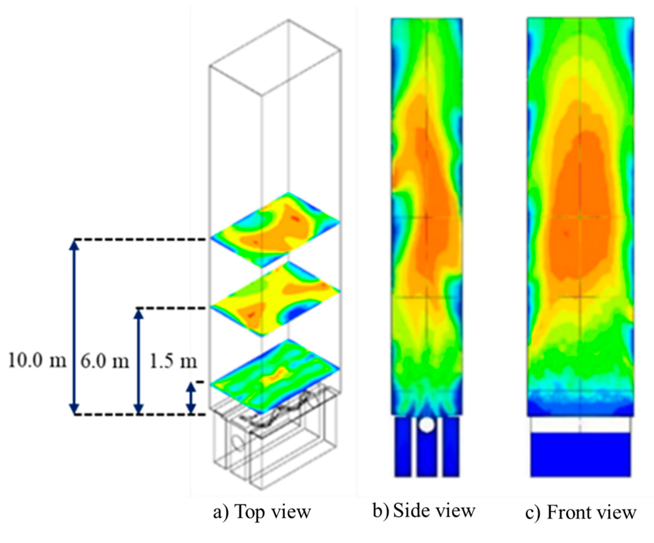
2.5. Temperature Distribution Analysis

Following our calculation of the combustion model, the temperature distribution was analyzed using the above combustion equations. The color scale of temperature distribution was applied to compare the flame temperatures in the reaction zone and unburned zone. The example of temperature distribution was analyzed on three planes, which were defined above the burner at elevations of 1.5, 6.0, and 10.0 cm, as shown in Figure 5a. The average temperature distributed on each plane was determined. The combustion characteristics of the middle plane at a side view and front view are shown in Figure 5b and Figure 5c, respectively.

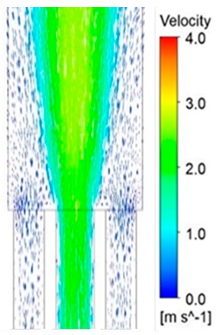
2.6. Velocity Streamline Analysis

According to our numerical calculations, the mixture flow was analyzed to observe the velocity streamline, flow direction, vortex flow, and the flows of other physical mixtures. The velocity streamline was applied to demonstrate fuel–air mixing and to predict combustion characteristics. Figure 6 shows an example of the analysis of the air and fuel velocity streamlines on the burner. The mixing between air (from the air slot) and fuel (from the fuel slots), the burner’s geometrical effects, and the flow behavior of the vortex were studied.

3. Results and Discussion

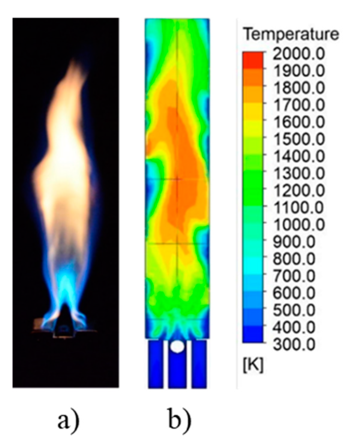
3.1. Validation of the PBSB Model

Velocity Profile on the PBSB

Following the validation of the model through the simulation results, the air and fuel flow velocities on the front and side views of the PBSB model were obtained and are shown in Figure 7a,b. The simulation results showed that the air velocity was raised by the influence of the bluff body and a vortex flow was observed. The fuel induced by the higher-velocity air stream is also observed in Figure 7b.
Following the numerical methodology, LPG combustion was analyzed on the PBSB model to validate the previous experimental results at Φ = 1.0. Figure 8 shows the (a) flame shape and (b) temperature distribution from the side view of the PBSB. Figure 9 shows the (a) flame shape and (b) temperature distribution from the front view of the PBSB. The results showed that the flame temperature distribution above the burner was lower than in the reaction zone and the unburned zone, which was comparable to the experimental results. As a lower temperature around the flame was observed in the experimental result, a lower temperature distribution influenced by environmental temperature was also represented. The comparison between the simulation and experimental results showed that the flame shape and temperature distribution represented a premixed flame and luminous flame reaction zone. Following combustion mechanisms, the chemical reaction was applied and the flame temperature from LPG combustion was obtained by numerical analysis. For the space above the reaction, referred to as the unburned zone, a diffusion flame with a higher temperature than in the reaction zone was observed owing to its lower air velocity; hence, heat accumulation occurred due to reburned fuel from the reaction zone. The obtained simulation results showed that the temperature distribution in the reaction and unburned zones was the same as that of the experimental results. It was concluded that the boundary conditions for the simulation setup were validated and acceptable. Simulated flame temperatures of 856.2 °C, 1529.02 °C, and 1545.6 °C were observed at 1.5 cm, 6.0 cm, and 10.0 cm over the burner’s surface. When comparing the experimental and simulation results, a 1.31% difference was obtained, and 500,000 mesh elements were applied. This model could be applied and modified for further investigations.

3.2. Combustion Analysis of the Porous Vortex Generator Slot Burner (PVGSB) Model

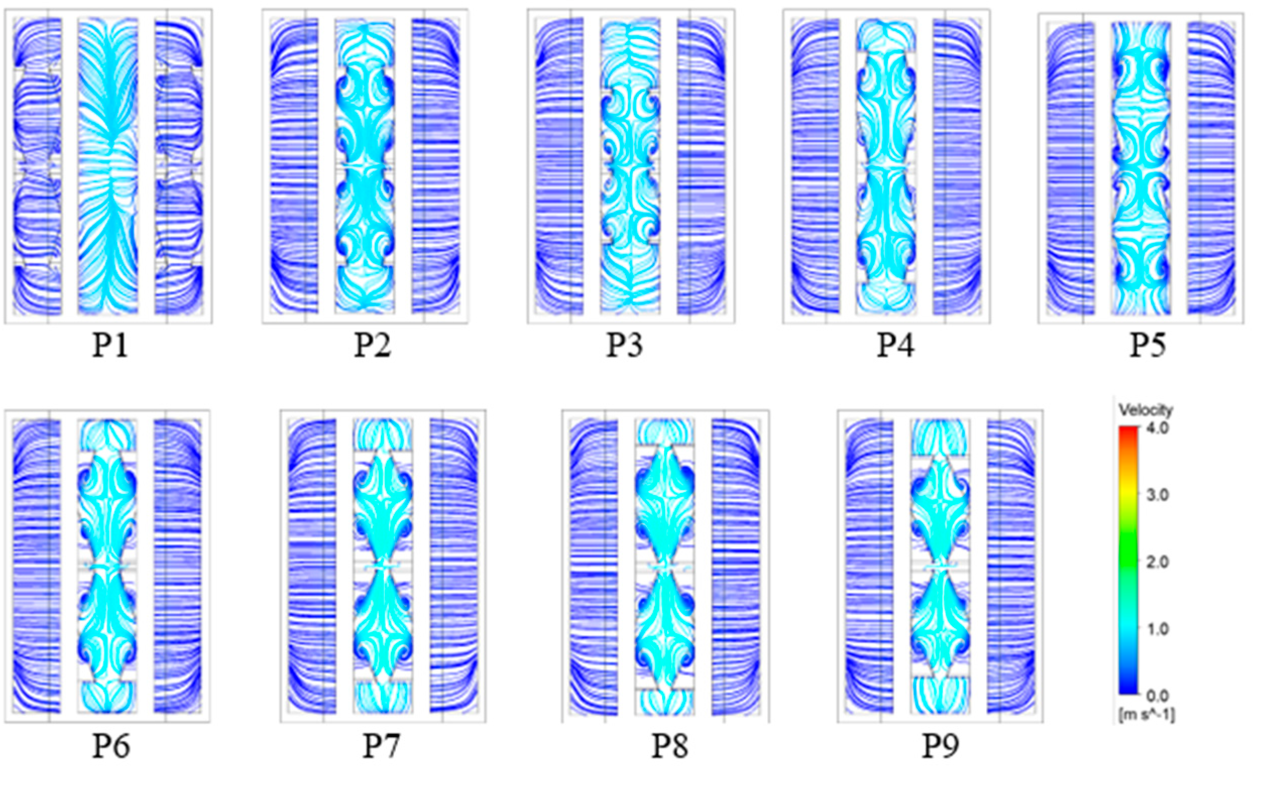
3.2.1. Velocity Profile of the PVGSB

The PVGSB model was developed from a PBSB with the vortex generator (VG) parameters of position, angle, direction, aspect ratio, and distance, which are given in Table 1 for cases P1–P9. Figure 10, Figure 11 and Figure 12 show the velocity streamlines of fuel and air for the top view, side view, and front view of the PVGSB, respectively. Following the numerical conditions, a comparison of the velocity streamline affected by the position of the VG on either the fuel (F) or air (A) slot is shown in P1 and P2. Figure 10 and Figure 11 show the velocity streamline from the top and side views of the PVGSB model, respectively. Then, cases P2–P9 were conducted for the other parameters with VG added to the air (A) slot. When the vortex angle increased from 30° to 45° and 60°, as shown in cases P3, P2, and P4, a vortex was observed for the top view, and the air and fuel velocity streamlines looked similar on the side view and front view of the PVGSB. The parameters related to the VG directions of clockwise (CW) and counterclockwise (CCW) were also studied and compared in cases P4 and P5, respectively. The results show that the vortex flow was influenced in both the CW and CCW directions. Another important parameter of VG, the aspect ratio (AR), was varied by 0.2, 0.3, and 0.4 and studied in cases P4, P6, and P7, respectively. Moreover, the velocity streamline from the front view of the PVGSB model is shown in Figure 12. When the AR increased to 0.3 and 0.4, reduced vortex and swirl velocity streamline were observed from the top view and side view of the PVGSB. Moreover, the VG distances of 0, 1.0, and 2.0 mm were used to study the physical mixture flow, as presented in cases P9, P7, and P8. When the distance between VGs was greater, the velocity streamline from the top view and side view of the burner model looked similar. However, a wider VG distance affected the non-uniform velocity streamline on the front view of the PVGSB.
Figure 13 shows the average air velocities in the x, y, and z axes on burner models and cases P1-P9 are compared. The results show that the air velocity on the PVGSB burner model could be enhanced at a VG angle of 60°, CW direction, and AR = 0.4. Moreover, the superficial velocity was observed at 0, 0.1 and 0.2 mm of VG distance for the x, y and z axes due to the decrease in the air slot area and affected the vortex flow.

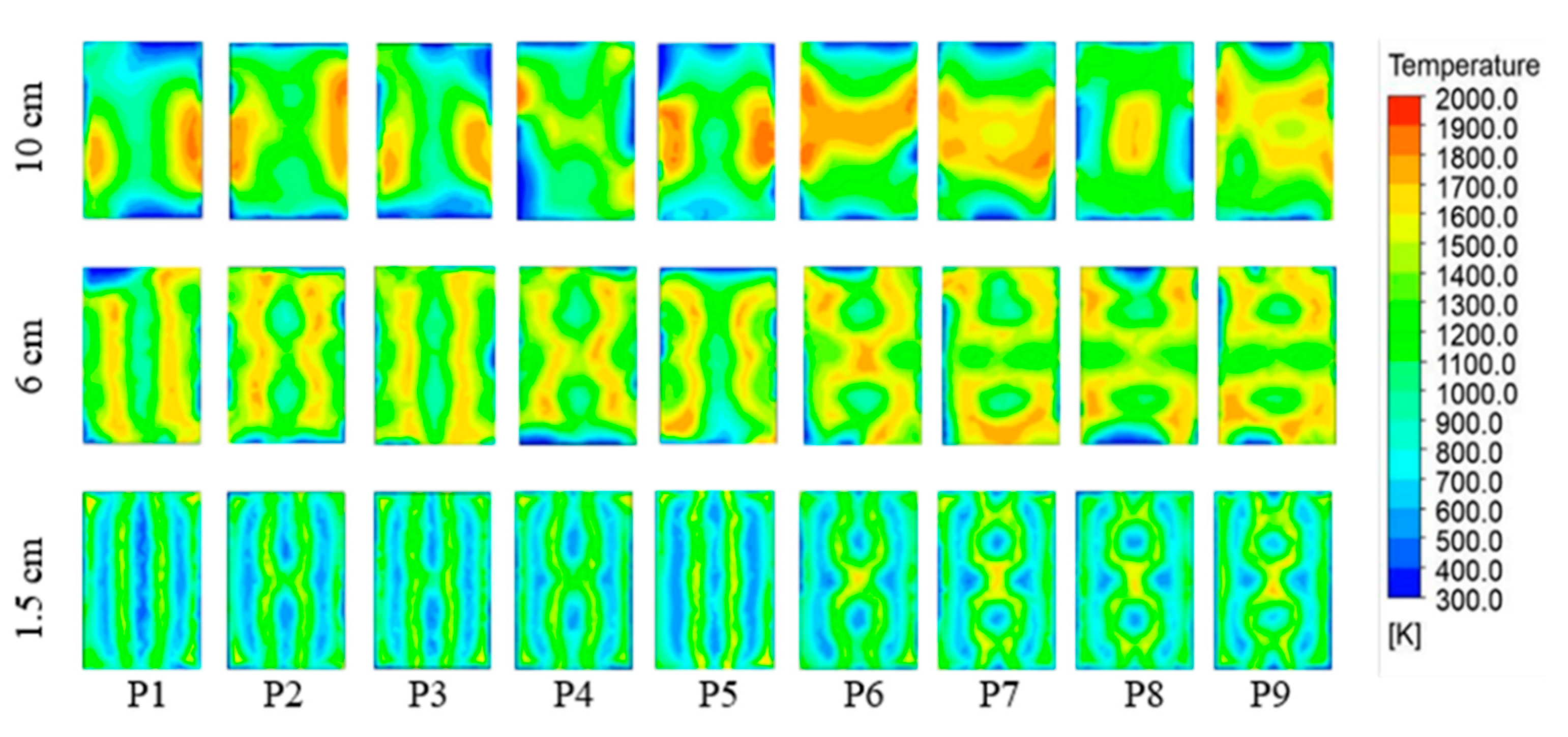
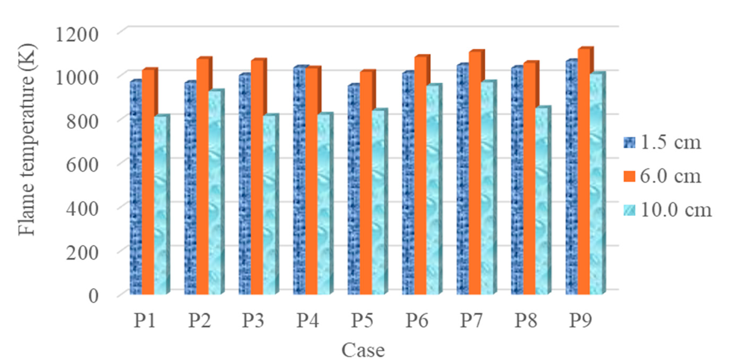
3.2.2. Temperature Distribution on the PVGSB

Following the parametric study of the PVGSB model (Figure 6), the temperature distributions of fuel and air from the top and side views of the PVGSB, as affected by the position of the VG on the fuel (F) and air (A) slots, are shown in P1 and P2. Figure 14, Figure 15 and Figure 16 show the temperature distribution on the side and top views of the PVGSB when the VG was added to a slot burner. Figure 14 shows the temperature distribution from the top view of the PVGSB when the VG was added to the air (A) slot of the slot burner. Compared to when the VG was added to the fuel (F) slot, a higher flame temperature was observed, as illustrated in Figure 15. The VG was applied to the air (A) slot when studying the other parameters in cases P2–P9. The increase in the vortex angle of 30°, 45°, and 60° affected the velocity streamlines, which were similar for cases P3, P2, and P4, respectively. However, the vortex flow and a higher temperature were observed at a 60° vortex angle (P4). The results obtained by varying the VG direction either clockwise (CW) or counterclockwise (CCW) were compared in cases P4 and P5. The results showed a reduced temperature distribution in case P5 (CCW) compared to case P6 (CW) due to worse mixing of the mixture; moreover, a higher flame temperature was observed in case P6 (CW). In addition, the aspect ratio (AR) and VG distance were also studied. The aspect ratios of 0.2, 0.3, and 0.4 were analyzed in cases P4, P6, and P7, respectively. When the AR increased to 0.3 and 0.4, wider temperature distributions and higher temperatures in the reaction zone were observed from both the side and top views of the PVGSB. In addition, the VG distances of 0, 1.0, and 2.0 mm were applied to study the physical mixture flow in cases P9, P7, and P8. Figure 16 shows the flame temperature at 1.5, 6.0, and 10.0 cm above the burner for the PVGSB model. When the distance between the VGs was greater, a lower temperature distribution was observed on the side view, and the lowest temperature distribution was shown at a 2.0 mm VG distance.

3.3. Combustion Analysis of the Vortex Generator Slot Burner (VGSB) Model

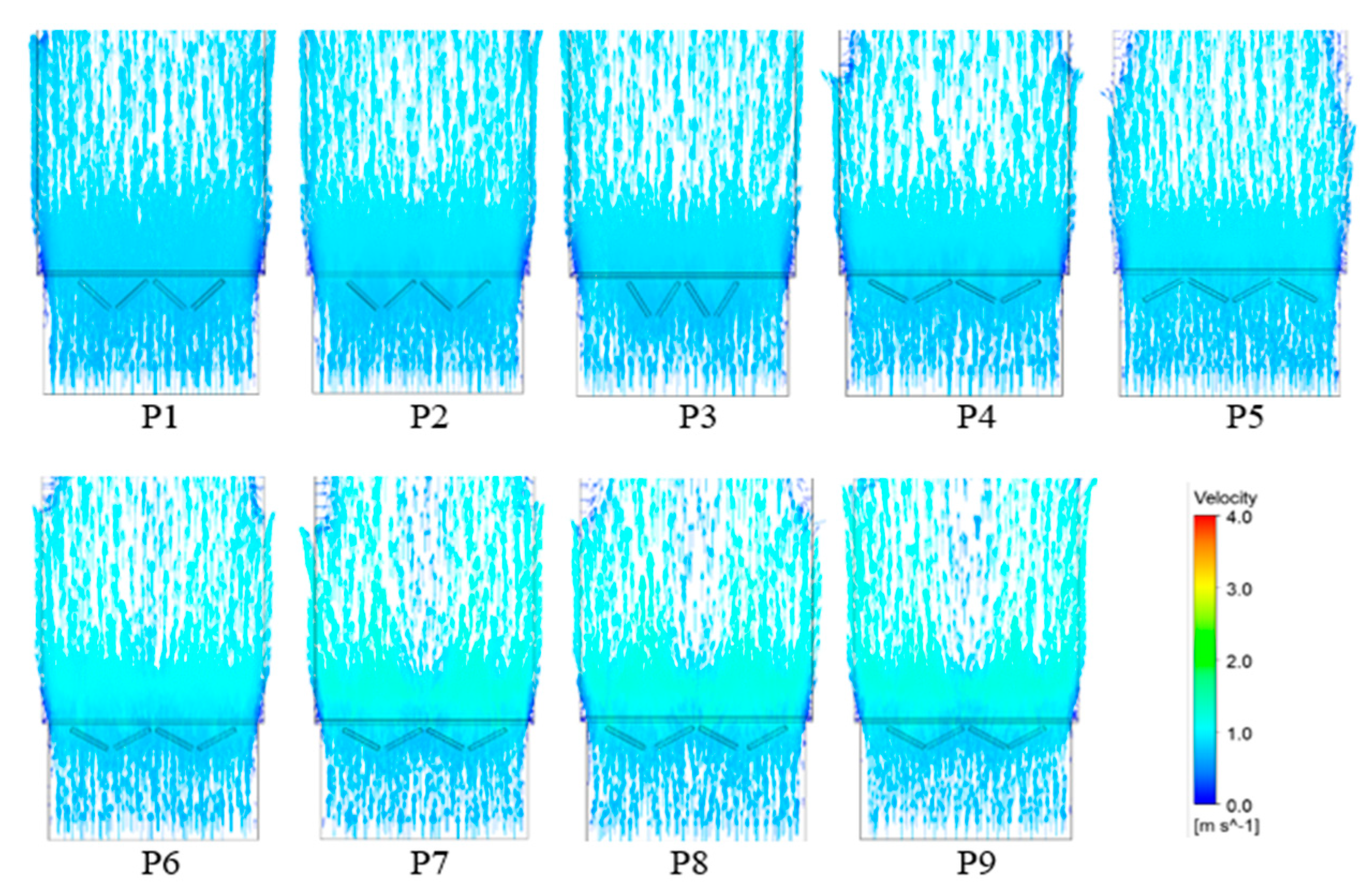
3.3.1. Velocity Profile on the VGSB

The velocity streamlines from the top view, side view, and front view of the VGSB model are shown in Figure 17, Figure 18 and Figure 19. Following our numerical study of the temperature distribution, the influence of the bluff bodies on air and fuel velocity were investigated in the VGSB model. The cylindrical, triangular, and reverse triangular bluff-body shapes were applied on the VGSB-C, VGSB-T, and VGSB-RT models. Figure 17 and Figure 18 show the velocity streamline from the top view of the VGSB model. Compared to the VGSB-C model, a stronger vortex was observed on the top view, side view, and front view of the VGSB-T and VGSB-RT models. The velocity streamline from the top view of the VGSB model is also shown in Figure 19. Though a vortex was observed on both the VGSB-T and VGSB-RT models, a higher velocity and swirl flow were also shown on the VGSB-RT model. The higher velocity, vortex, and swirl flow observed on the VGSB-RT model could enhance the flame temperature due to the well-mixed air and fuel.

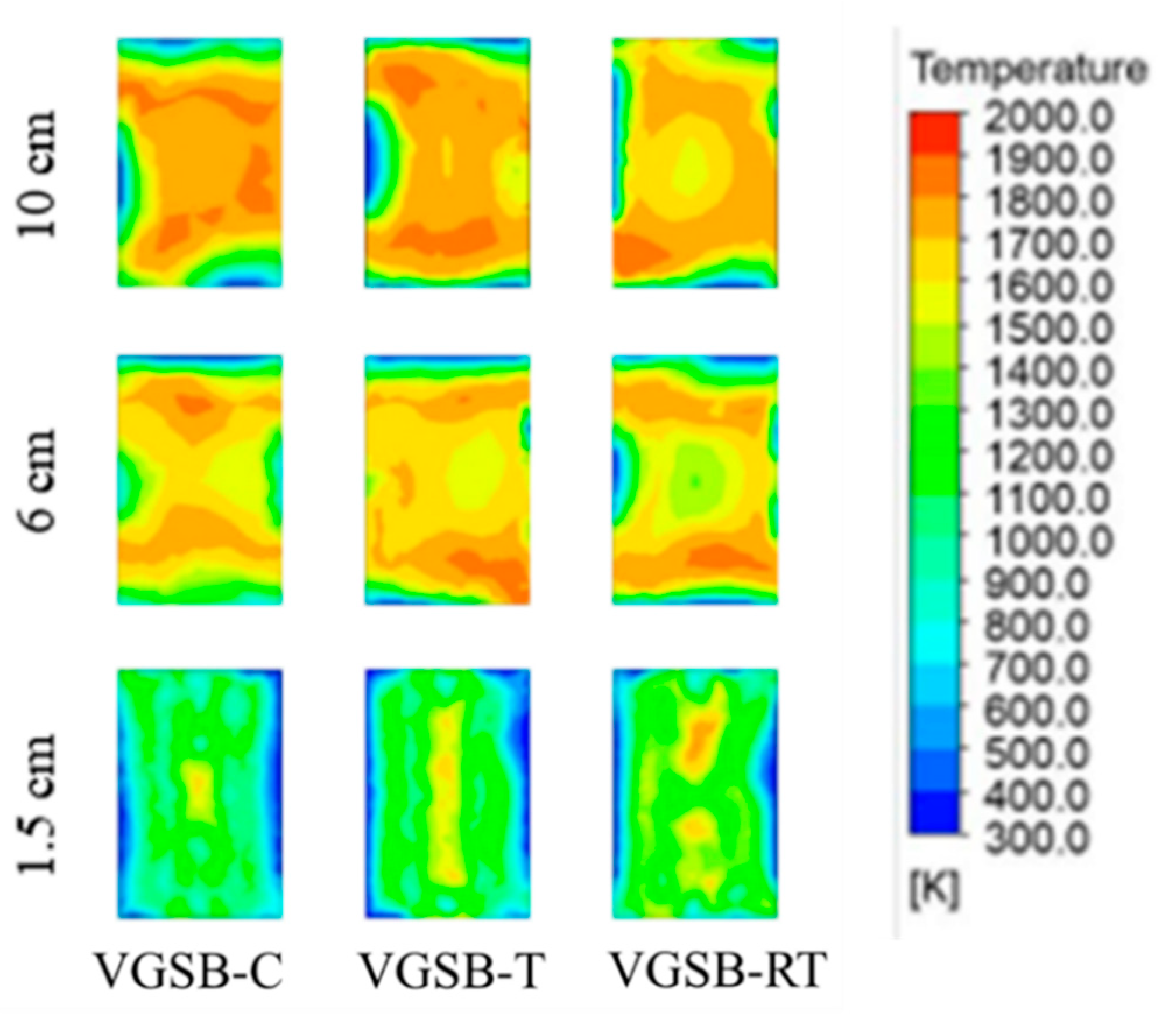
3.3.2. Temperature Distribution in the VGSB

Following the numerical study of the PVGSB model, the parameters of the VG were examined. Figure 20 shows the temperature distribution from the side view of the VGSB model. For case P9, flame temperatures of 1065.2 K, 1120.1 K, and 1006.2 K were observed at 1.5 cm, 6.0 cm, and 10.0 cm, and the flame temperature was approximately 24.4% higher at 1.5 cm due to the vortex generator. Figure 21 shows the flame temperature at 1.5, 6.0, and 10.0 cm above the burner for the VGSB model. As the influence of bluff bodies was examined in previous research on PBSBs, it was interesting to study the bluff bodies designed for the PVGSB. Thus, cylindrical, triangular, and reverse triangular bluff-body shapes were used with VG and are referred to as the VGSB-C, VGSB-T, and VGSB-RT models, respectively.
Moreover, the flame temperatures at 1.5, 6.0, and 10.0 cm above the burner for the VGSB model are summarized in Figure 22. Compared to the VGSB-C model, the widest temperature distribution and highest temperature (1154.8 K) on VGSB-RT were observed on the side view and top view of the VGSB model. Moreover, the flame temperature on the VGSB-T and VGSB-RT models was improved. In addition, the reverse triangular bluff body with a VG on the VGSB model enhanced the combustion and showed a 34.8% higher flame temperature compared to the PBSB model.

4. Conclusions

This research focused on how a vortex generator affected the physical fluid flow and LPG combustion characteristics of our referenced porous bluff-body slot burner model (PBSB). The temperature distribution and mixture flow velocity on the PBSB model were validated with the experimental results of our referenced research. The parameters of VG position (fuel (F) and air (A) slots), direction (CW and CCW), aspect ratio (AR), and distance (S) were investigated in our enhanced PBSB model, referred to as the PVGSB model. It was found that the VGSB model with a VG angle (A) of 60°, a CW direction, an aspect ratio (AR) = 0.4, and a VG distance (S) = 0 mm could enhance the flame temperature by 24.4% at 1.5 cm over the burner surface due to a greater influence of the vortex. Moreover, the reverse triangular bluff body applied to the VGSB model had a stronger effect on the vortex and swirl mixture flow compared to the cylindrical bluff body. The vortices occurring at the exit channel and the increased air velocity were induced by the reverse triangular bluff body applied to the VGSB model, which promotes air–fuel mixing, leading to 34.9% higher combustion temperatures compared to the referenced PBSB model. Our numerical study of LPG combustion on a slot burner with a VG and reverse triangular bluff body, or the VGSB model, could be applied to enhancing the combustion characteristics of physical air–fuel flow and flame temperature.

Author Contributions

Investigation, M.P.; Writing—review & editing, A.K. All authors have read and agreed to the published version of the manuscript.

Funding

This research project was funded by the Thailand Science Research and Innovation (TSRI) Basic Research Fund: Fiscal year 2023 under grant number [FRB670016/0164].

Data Availability Statement

The original contributions presented in the study are included in the article, further inquiries can be directed to the corresponding author.

Acknowledgments

The authors thank the Department of Mechanical Engineering, Faculty of Engineering, King Mongkut’s University of Technology Thonburi for the financial support and experimental facilities.

Conflicts of Interest

The authors declare no conflict of interest.

Nomenclature

Abbreviations
ARAspect ratio [-]
C a 1 Constant value of two for the intermittency equation [-]
C a 2 Constant value of 0.006 for the intermittency equation [-]
C e 1 Constant value of one for the energy equation [-]
C e 2 Constant value of 50 for the energy equation [-]
  F Gravitational   body   forces     F = ρ g , [N/m3]
F length Empirical correlation for length of the transition region [-]
HEnthalpy [kJ/mol]
J j ̿ Diffusion flux of species j [kg/m2 s]
k eff Effective thermal conductivity [W/m K]
k t Turbulent thermal conductivity [W/m K]
PStatic pressure [bar]
SDistance between VGs [mm]
S h Heat of chemical reaction [kJ/mol]
SmMass added on continuous phase [kg]
Symbols
μ Dynamic viscosity [N. s/m2]
ΦEquivalence ratio [-]
γ Intermittency
τ̿Stress tensor [N/m2]
Ω Vorticity magnitude [Hz]
θVortex generator angle [°]

References

  1. Energy Policy and Planning Office, Energy Overview. Available online: https://anyflip.com/qivjx/nvxn/ (accessed on 1 January 2024).
  2. PTT, Knowledge and Safety with Cooking Gas. Available online: http://www.gastechelectronics.com (accessed on 1 September 2023).
  3. Office of Energy Policy and Planning, LPG. Available online: https://www.eppo.go.th/images/Infromation_service/Publication/Knowledge/LPG%20fuel.pdf (accessed on 25 December 2023).
  4. Department of Alternative Energy Development and Efficiency, Ministry of Energy, Training Textbook for Persons Responsible for Thermal Energy, Part 2, Chapter 3, Theory of Combustion. Available online: http://www2.dede.go.th/bhrd/old/file_handbook.html (accessed on 7 September 2023).
  5. Engineering Toolbox, Gas Density. Available online: https://www.engineeringtoolbox.com/gas-density-d_158.html (accessed on 7 September 2023).
  6. Ministry of Energy, Regulations and Methods of Storage, Assignment of Responsible Special Personel, and Exemption to Follow the Hazardous Substances Act 1992 (B.E.2535) for Areas of Liquefied Petroleum Gas Responsible by the Department of Energy Business. Available online: http://elaw.doeb.go.th/document_doeb/EN/347_0001.pdf (accessed on 15 May 2024).
  7. Jugjai, S. Combustion; Chulalongkorn University Press: Bangkok, Thailand, 2004; pp. 49–55, 91–95, 206–207, 234–235, 575–577. [Google Scholar]
  8. Kwok, L.C.; Leung, C.W.; Cheung, C.S. Heat Transfer Characteristics of Slot and Round Premixed Impinging Flame Jets. Exp. Heat Transf. 2003, 16, 111–137. [Google Scholar] [CrossRef]
  9. U.S. Centennial of Flight Commission, 1991, Aerodynamic Resistance and the Use of Aerodynamic Coefficients. Available online: https://www.centennialofflight.net/essay/Theories_of_Flight/TH-OV.htm (accessed on 15 May 2024).
  10. Patel, V.; Shah, R. Experimental investigation on flame appearance and emission characteristics of LPG inverse diffusion flame with swirl. Appl. Therm. Eng. 2018, 137, 377–385. [Google Scholar] [CrossRef]
  11. Caliskan, S. Experimental investigation of heat transfer in a channel with new winglet-type vortex generators. Int. J. Heat Mass Transf. 2014, 78, 604–614. [Google Scholar] [CrossRef]
  12. Zheng, Y.; Yang, H.; Mazaheri, H.; Aghaei, A.; Mokhtari, N.; Afrand, M. An investigation on the influence of the shape of the vortex generator on fluid flow and turbulent heat transfer of hybrid nanofluid in a channel. J. Therm. Anal. Calorim. 2021, 143, 1425–1438. [Google Scholar] [CrossRef]
  13. Ke, Z.; Chen, C.L.; Li, K.; Wang, S.; Chen, C.H. Vortex dynamics and heat transfer of longitudinal vortex generators in a rectangular channel. Int. J. Heat Mass Transf. 2018, 132, 871–885. [Google Scholar] [CrossRef]
  14. Promthaisong, P.; Promvonge, P.; Khanoknaiyakarn, C.; Skullong, S. Numerical Heat Transfer Investigation in a Solar Receiver Heat Exchanger Channel with Punched Elliptical-Winglet Vortex Generators. Eng. J. 2021, 25, 105–114. [Google Scholar] [CrossRef]
  15. Raykowski, K.A. Optimization of a Vortex Generator Configuration for a 1/4-Scale Piper Cherokee Wing; Embry-Riddle Aeronautical University: Daytona Beach, FL, USA, 1999; p. 24. [Google Scholar]
  16. Du, X.; Feng, L.; Li, L.; Yang, L.; Yang, Y. An investigation on the influence of the shape of the vortex generator on fluid flow and turbulent heat transfer of hybrid nanofluid in a channel. Int. J. Heat Mass Transf. 2014, 75, 368–380. [Google Scholar] [CrossRef]
  17. Fouatih, O.M.; Medale, M.; Imine, O.; Imine, B. Design optimization of the aerodynamic passive flow control on NACA 4415 airfoil using vortex generators. Eur. J. Mech. B/Fluids 2016, 56, 82–96. [Google Scholar] [CrossRef]
  18. Olfian, H.; Zabihi Sheshpoli, A.; Mousavi Ajarostaghi, S.S. Numerical evaluation of the thermal performance of a solar air heater equipped with two different types of baffles. Heat Transf. 2020, 49, 1149–1169. [Google Scholar] [CrossRef]
  19. PTT, Factors that Make the Combustion Complete. Available online: https://dscng.pttplc.com (accessed on 8 September 2023).
  20. Hamdi, M.; Rouaud, O.; Tarlet, D.; Havet, M. Experimental investigation on convective heat transfer enhancement by EHD in wire to plate configuration. Therm. Sci. Eng. Prog. 2021, 26, 101086. [Google Scholar] [CrossRef]
  21. Mahesh, S.; Mishra, D.P. Flame stability and emission characteristics of turbulent LPG IDF in a backstep burner. Fuel 2008, 87, 2614–2619. [Google Scholar] [CrossRef]
  22. Mahesh, S.; Mishra, D.P. Flame structure of LPG-air Inverse Diffusion Flame in a backstep burner. Fuel 2010, 89, 2145–2148. [Google Scholar] [CrossRef]
  23. Rabee, B.A. The Effect of Inverse Diffusion Flame Burner-Diameter on Flame Characteristics and Emissions. Energy 2018, 160, 1201–1207. [Google Scholar] [CrossRef]
  24. Bagheri, G.; Hosseini, S.E.; Wahid, M.A. Effects of bluff body shape on the flame stability in premixed micro-combustion of hydrogen-air mixture. Appl. Therm. Eng. 2014, 67, 266–272. [Google Scholar] [CrossRef]
  25. Sudjan, T.; Jugjai, S.; Kaewpradap, A. Combustion Characteristics of C3H8/C4H10 Flames affected by Air Flow Bluff Body on Non-Premixed Slot Burner. Suranaree J. Sci. Technol. 2021, 28, 010044. [Google Scholar]
  26. Strehlow, R.A. Combustion Fundamentals, McGraw-Hill Series in Energy, Combustion and Environment; McGraw-Hill College: New York, NY, USA, 1985; p. 27. ISBN 0-07-Y66599-0. [Google Scholar]
  27. Ansys Innovation Courses. Available online: https://innovationspace.ansys.com/courses/wp-content/uploads/2020/06/Governing-Equations-of-Fluid-Dynamics-Lesson4-Conservation-of-Momentum-Handout.pdf (accessed on 25 January 2024).
Figure 1. Burner models. (a) Slot burner (SB) model, (b) porous slot burner (PSB) model, and (c) porous bluff body slot burner (PBSB).
Energies 17 04608 g001
Figure 2. VG positions on the PSB model.
Energies 17 04608 g002
Figure 3. Burner models with a vortex generator. (a) Porous vortex generator slot burner (PVGSB) model and (b) Vortex generator slot burner (VGSB) model.
Energies 17 04608 g003
Figure 4. Simulation boundary for (a) the schematic of the referenced experiment and (b) VGSB model.
Energies 17 04608 g004
Figure 5. Example of the temperature distribution.
Energies 17 04608 g005
Figure 6. Example of the velocity streamline analysis.
Energies 17 04608 g006
Figure 7. Air and fuel flow velocity vectors from the side view of the PBSB.
Energies 17 04608 g007
Figure 8. Comparison of LPG combustion from the experiment and simulation consisting of (a) the flame shape and (b) temperature distribution from the side view of the PBSB.
Energies 17 04608 g008
Figure 9. Comparison of LPG combustion from the experiment and simulation consisting of (a) the flame shape and (b) temperature distribution from the front view of the PBSB.
Energies 17 04608 g009
Figure 10. Velocity streamlines from the top view of the PVGSB model.
Energies 17 04608 g010
Figure 11. Velocity streamlines from the side view of the PVGSB model.
Energies 17 04608 g011
Figure 12. Velocity streamlines from the front view of the PVGSB model.
Energies 17 04608 g012
Figure 13. Comparison of average air velocities in the x, y, and z axes on burner models for cases P1–P9.
Energies 17 04608 g013
Figure 14. Temperature distribution from the side view of the PVGSB model.
Energies 17 04608 g014
Figure 15. Temperature distribution from the top view of the PVGSB model.
Energies 17 04608 g015
Figure 16. Flame temperatures at 1.5, 6.0, and 10.0 cm above the burner for the PVGSB model.
Energies 17 04608 g016
Figure 17. Velocity streamlines from the top view of the VGSB model.
Energies 17 04608 g017
Figure 18. Velocity vectors from the side view of the VGSB.
Energies 17 04608 g018
Figure 19. Velocity vectors from the front view of the VGSB.
Energies 17 04608 g019
Figure 20. Temperature distributions from the side view of the VGSB model.
Energies 17 04608 g020
Figure 21. Temperature distributions from the top view of the VGSB model.
Energies 17 04608 g021
Figure 22. Flame temperatures at 1.5, 6.0, and 10.0 cm above the burner for the VGSB model.
Energies 17 04608 g022
Table 1. Computational conditions of LPG combustion in the PVGSB model with VG parameters.
CasePositionAngle (θ)DirectionAspect RatioDistance
FA30°45°60°CWCCW0.20.30.4012
P1
P2
P3
P4
P5
P6
P7
P8
P9
Table 2. Computational conditions of LPG combustion on the VGSB model with bluff-bodyshapes.
CasePositionAngleDirectionAspect RatioDistanceBluff-Body Shape
A60°CW0.40 mm
VGSB-CCylinder
VGSB-TTriangle
VGSB-RTReverse triangle
Table 3. Boundary conditions.
Boundary Condition at the Burner InletUnitValue
C3H8 [%]0.7
C4H10 [%]0.3
Airflow rate [L/min]20
Air pressure [Pa]202,650
Fuel pressure[Pa]101,325
Fuel inlet velocity[m/s]0.0537
Mesh [elements]200,000–500,000
Emissivity [-]0.44
Heat transfer coefficient [W/m2·K]400
Disclaimer/Publisher’s Note: The statements, opinions and data contained in all publications are solely those of the individual author(s) and contributor(s) and not of MDPI and/or the editor(s). MDPI and/or the editor(s) disclaim responsibility for any injury to people or property resulting from any ideas, methods, instructions or products referred to in the content.

