Article

The Effects of Turbine Guide Vanes on the Ignition Limit and Light-Round Process of a Triple-Dome Combustor

1
Institute of Engineering Thermophysics, Chinese Academy of Sciences, Beijing 100190, China
2
School of Aeronautics and Astronautics, University of Chinese Academy of Sciences, Beijing 100049, China
3
National Key Laboratory of Science and Technology on Advanced Light-Duty Gas-Turbine, Beijing 100190, China
4
Qingdao Institute of Aeronautical Technology, Qingdao 266500, China
*
Author to whom correspondence should be addressed.
Energies 2024, 17(18), 4636; https://doi.org/10.3390/en17184636
Submission received: 24 June 2024 / Revised: 27 August 2024 / Accepted: 31 August 2024 / Published: 17 September 2024

Abstract

:
This experimental study investigated the influence of different turbine guide vane parameters on the ignition limit and light-round processes in a triple-dome combustor. It was found that for the triple-dome combustor, the minimum fuel/air ratios at the ignition limit all show a trend of initial decrease followed by subsequent increase with the growth of incoming air mass flow rate. The ignition fuel/air ratio decreases with the increase in turbine blockage ratio, and the optimal scheme is achieved with a blockage ratio of 0.8. Under the condition where the incoming air mass flow rate is 0.089 kg/s, the light-round time decreases with the increase in fuel/air ratio, and the light-round time of the combustor without guide vanes is shorter than that of the other schemes. With the increase in incoming air mass flow rate, the light-round time of the schemes with guide vanes is shortened. Under the same incoming air mass flow rate and fuel/air ratio, the increase in the blockage ratio will lead to an increase in the light-round time of the triple-dome combustor.

1. Introduction

The development of high-performance aviation engines is moving toward low fuel consumption, high thrust-to-weight ratio, and high-temperature rise. This development requires modern aviation engine combustors operating under a high fuel/air ratio and high outlet temperature conditions [1,2]. The traditional engine design method is to design and then iteratively optimize the compressor, combustor, and turbine components separately. However, the combustor and turbine component design method under extreme thermal load is gradually evolving to an integrated coupled design method, which controls the high-temperature and low-temperature regions at the exit of the combustor to ensure that the hot spots pass exactly through the channels between the guide vanes, while the cold spots traverse the surface of the blades, which achieves efficient blade cooling and improves the lifespan of turbine blades.
Most research on interactions between combustor and turbine focuses on the impact of the combustor exit hot spots and temperature distribution on the downstream turbine. However, there is a lack of studies regarding the influence of the turbine on the upstream combustor. In the 1980s, Escudier [3] found that variations in the outlet flow area affect the shape and velocity of the upstream recirculation zone. Hilgert [4] et al. investigated the aerothermal interaction of the coupled combustor and turbine based on the Large Eddy Scale Turbine Rig (LSTR) test bench.
The high subsonic test bench, with a swirl combustion chamber and turbine coupling, built by the University of Oxford [5], enables research into the interaction between swirl and turbulence, focusing on the characteristics of turbine guide vanes regarding upstream flow fields and changes in aerothermal parameters. Zhejiang University [6] has installed turbine guide vanes at the outlet of an annular combustor, carrying out ignition and light-round experiments with or without guide vanes on the test bench. Ye Chenran et al. [7] found that the circumferential ignition time is shorter in annual combustor equipment with turbine guide vanes. They compared it with the results of the Large Eddy Simulation and discovered that the ignition and light-round time were tallied with the experimental values. By studying the ignition process in different combustors, Wang Hui [8] discovered that the turbine guide vanes cause flame shape deviation and alter the direction of propagation. In numerical simulation, NASA [9] conducted research on the flow field of the combustor coupled with the turbine guide vanes and found that different arrangements of guide vane affect the outlet velocity field distribution. Klapdor [10] performed a Reynolds-averaged numerical simulation on the effect of the presence or absence of guide vanes at the outlet of rich-burn, quench, and lean-burn combustors on the organization of the upstream flow field. The study indicated that the guide vanes have a significant impact on the axial velocity near the downstream region of the main combustion zone in the combustor. Zhou Jie et al. [11,12] conducted a numerical simulation study on the flow and heat transfer at a turbine outlet by the Very Large Eddy Simulation method and the SST k-ω turbulence model under a high Reynolds number, considering the coupling between combustor and turbine.
Most of the research on the ignition and light-round processes was conducted in single-dome model combustors, to multi-dome linear combustor models and multi-dome swirling sector combustors, to annual combustors. Renou [13] found that the flame propagation velocity of single-dome combustors is positively correlated with the turbulence intensity. Bach [14] et al., using high-speed cameras, discovered that in annular combustors, flame propagation occurs in a “sawtooth” pattern between adjacent nozzles. Machover [15] et al., through observing the ignition process in non-premixed multi-nozzle annular combustors, discovered differences in flame propagation speed between the two sides of the nozzles due to centrifugal force provided by the swirlers.
Barré [16] et al. investigated the ignition process of a multi-nozzle combustor by combining experimental and Large Eddy Simulation methods. They discussed the flame propagation process and time at different nozzle spacings. They found that the larger nozzle spacing led to the longer time required for the light-round, and a critical spacing for the flame propagation mechanism was found. Mastorakos and Machover [17] also investigated the ignition and light-round process of a swirl combustor. Their research revealed that the centrifugal force provided by the swirler accelerates the atomization and mixing of air and fuel, which would be more conducive to the ignition and thus reduce the ignition light-round time. Philip [18,19,20] et al. investigated the effects of different ignition methods, flow conditions, ignition energy, and other factors on the probability of successful methane gas ignition using the Large Eddy Simulation.
Contemporary research on the ignition limits and light-round processes in multi-head combustors generally approaches the combustion chamber as a unified entity. Numerical simulations or experimental analyses are typically performed using outlet boundary conditions prescribed at the turbine end. However, the presence of turbine guide vanes can lead to significant changes in the outlet boundary conditions of the combustor, resulting in alterations in the velocity distribution within the combustor, thus affecting the ignition and light-round processes. Therefore, integrating the combustion chamber and turbine guide vanes into a single system for experimental investigation offers a more accurate assessment of the ignition limits and light-round processes within the combustion chamber. Therefore, there is a need for in-depth research on the influence of turbine guide vanes on ignition and light-round processes in combustors.
This study focuses on experimental investigations of the coupling between the combustion chamber of a triple-dome aircraft engine model and the turbine guide vanes. Various turbine guide vane configurations were tested to explore their effects on the ignition and light-round process within the combustor. The study examines how different parameters of the turbine guide vanes influence the ignition boundary and light-round process within the combustor.

2. Experimental Setup

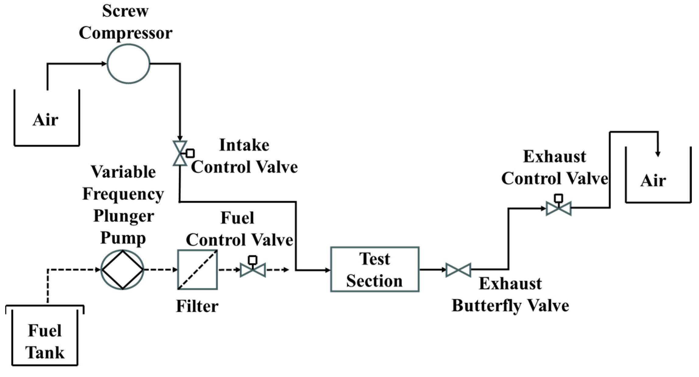
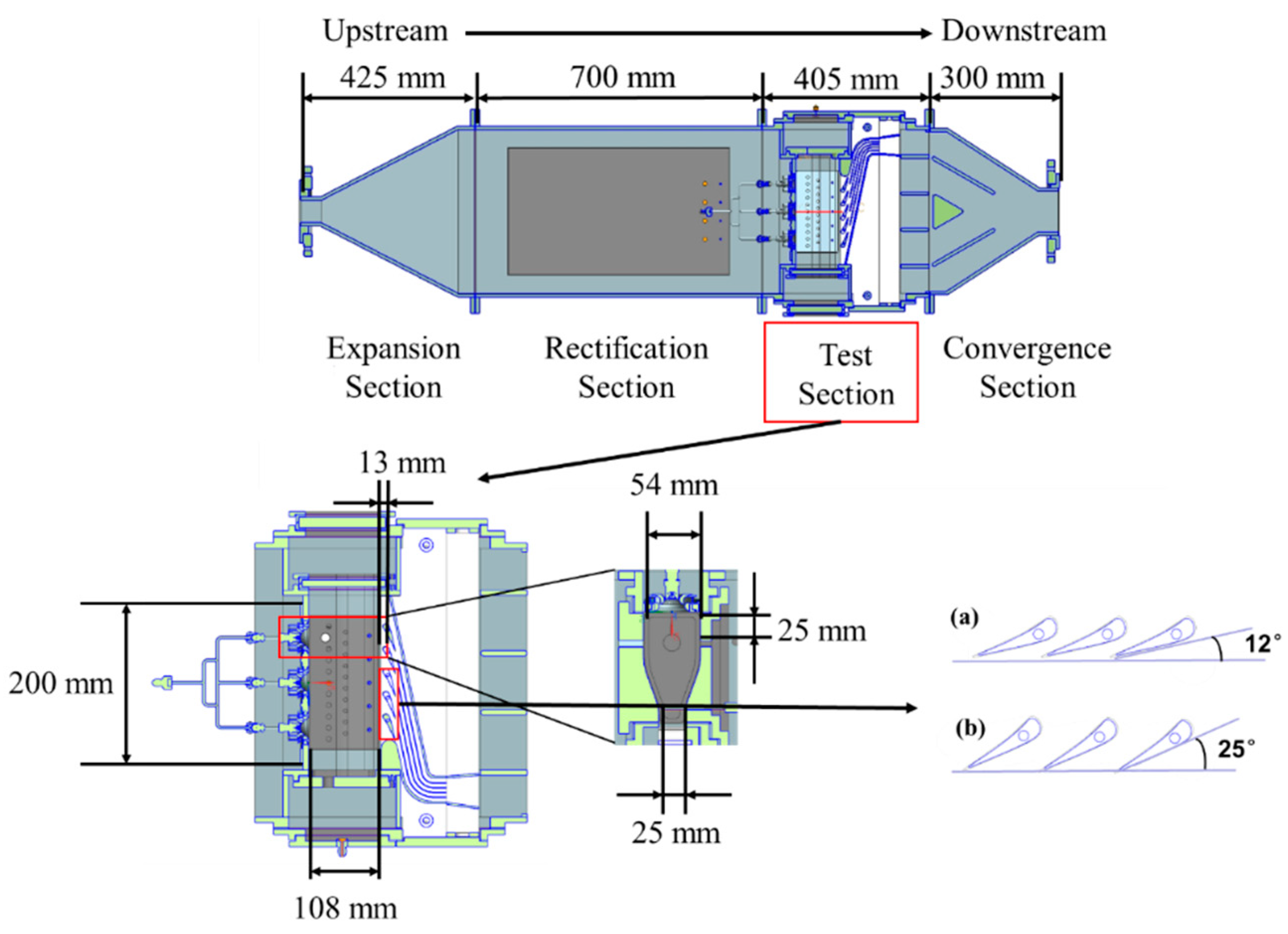
2.1. Flow Configuration

The experimental system in this paper is shown in Figure 1. Air was compressed by a screw compressor, dried, and then supplied to the combustor. The inlet air mass flow rate was regulated by an adjusting valve and mass flow meter in a range from 0.076 kg/s to 0.143 kg/s. The operating temperature and pressure were set to 300 K and 101.3 kPa, respectively, for all the examined cases. As shown in Figure 2, the air was delivered to an expansion section (425 mm), settled down in a rectification section (700 mm), and delivered to a turbine guide vane coupled with the triple-dome combustor test section (405 mm) and exhausted through a convergence section (300 mm). The fuel (RP-3) was delivered to the manifold by an oil pump at the same operating temperature as air with a mass flow rate range from 6.60 kg/h to 12.73 kg/h. Figure 2 also shows the dimensions of the triple-dome combustor section. The length of the triple-dome combustor section is 108 mm, and the total height is 200 mm, with the height of each dome being 67 mm, which also means that the space between adjacent nozzles is 67 mm. The widths of the combustor are 54 mm and 25 mm at the inlet and outlet of the chamber, respectively. The triple-dome combustor section is equipped with three centrifugal atomizing nozzles simultaneously supplied with fuel. The air was swirled by a dual-stage swirler with 19.5 mm and 48 mm for the first and second stage swirler diameters, respectively, for increasing fuel and air mixing and stabilizing the flame. Five turbine guide vanes were installed 13 mm downstream of the combustor to investigate the effect of turbine guide vanes on the ignition and light-round process of the triple-dome combustor. Details of the turbine guide vanes’ arrangement are shown in Figure 2a,b. The guide vane blockage ratio is designed between 0.6 and 0.8 (corresponding attack angles range from 25 degrees to 12 degrees), with intervals of 0.05; yields of 6 different turbine guide vane conditions are shown in Table 1. Sonic was not achieved in all the turbine guide vane conditions.
A specialized high-energy igniter designed for aviation engines with a spark energy of 2~3 J and a frequency of 3–5 Hz ignition was located 10 mm downstream from the swirler outlet in the #2 dome. This igniter was used to ignite the combustor. The criteria for successful ignition are as follows: (1) a sudden increase in pressure within the combustor; (2) a stable triple-dome flame for more than 10 s observed by an industrial camera. Fulfilling either of these criteria is considered successful ignition.

2.2. Measurement Methods and Image Processing

To further analyze the effect of the guide vanes on the ignition and light-round process between the domes, a Phantom v2012 high-speed camera (Phantom, Wayne, NJ, USA) with a resolution of 1280 × 800, 4000 Hz frame rate, was used to capture the CH* chemiluminescence during the ignition process and the flame light-round process of the triple-dome ignition. A 430 nm ± 10 nm bandpass filter was mounted on the lens of the high-speed camera to filter out other optical signals when capturing the CH* signal from the flame. The original images captured by the high-speed camera were subjected to MATLAB R2021a for pseudo-color processing. Additionally, an industrial camera (Lucid Vision Labs ATX204, Lucid Vision Labs, Richmond, BC, Canada) was used to monitor the flame conditions.

3. Results and Discussion

3.1. Turbine Guide Vanes’ Effect on the Ignition Limits of the Triple-Dome Combustor

To explore the turbine guide vanes’ effect on the ignition limits of the triple-dome combustor, we conducted the ignition limits experiment under air mass flow rates from 0.07 to 0.15 kg/s for the cases from 0 to 5, as shown in Figure 3.
It can be found that, under the same inlet air mass flow rate, the ignitable fuel-to-air ratios for the cases with turbine guide vanes were consistently lower than that for the case without turbine guide vanes. For the case without turbine guide vanes, the minimum ignitable fuel-to-air ratios reached their lowest value (0.0257) at an air mass flow rate of 0.089 kg/s. Subsequently, as the air mass flow rate increased, the minimum ignitable fuel-to-air ratio for the case without turbine guide vanes gradually increased to 0.301. In the meantime, for the cases with turbine guide vanes, the minimum ignitable fuel-to-air ratio decreased significantly with the increment of the inlet air mass flow rate. When the air mass flow rate reached 0.116 kg/s, the minimum ignitable fuel-to-air ratio reached its minimum value for case 1 to case 5. As the inlet air mass flow rate continued to increase beyond this point, the minimum ignitable fuel-to-air ratio increased. However, for the highest block ratio case, the minimum ignitable fuel-to-air ratio remained nearly constant when the air mass flow rate increased.
With the blockage ratio increased from 0.6 to 0.8, the minimum ignitable fuel-to-air ratio decreased by 15%; this suggests that the arrangement of the turbine guide vanes could influence the flow field in the combustor and then influence the minimum ignitable fuel-to-air ratio, which indicates that as the blockage ratio increases, the ignition characteristics of the combustion chamber are improved. In Figure 4, X = 45 mm is the location where the turbulent kinetic energy is highest on the Y = 0 mm plane. The igniter is located at Z = −66.5 mm during the ignition boundary experiment. It is found by collecting the data of turbulent kinetic energy at Z = −70 mm~−63 mm that as the blockage ratio increases, the turbulent kinetic energy gradually increases and is always higher than the scheme without guide vanes. This confirms the conclusion that increasing the blockage ratio can significantly enhance the minimum ignition boundary.

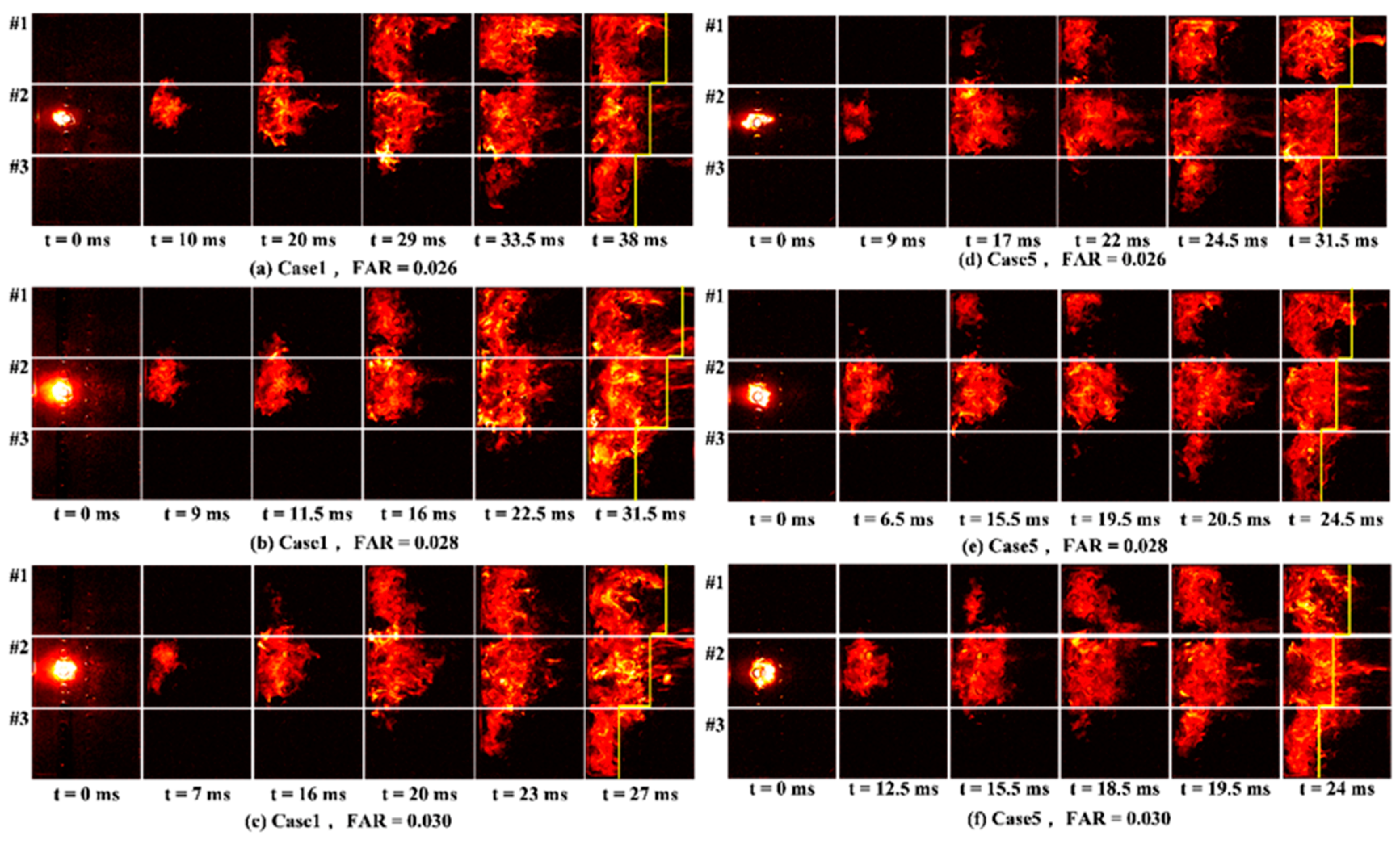
3.2. Analysis of Flame Propagation and Light-Round Processes

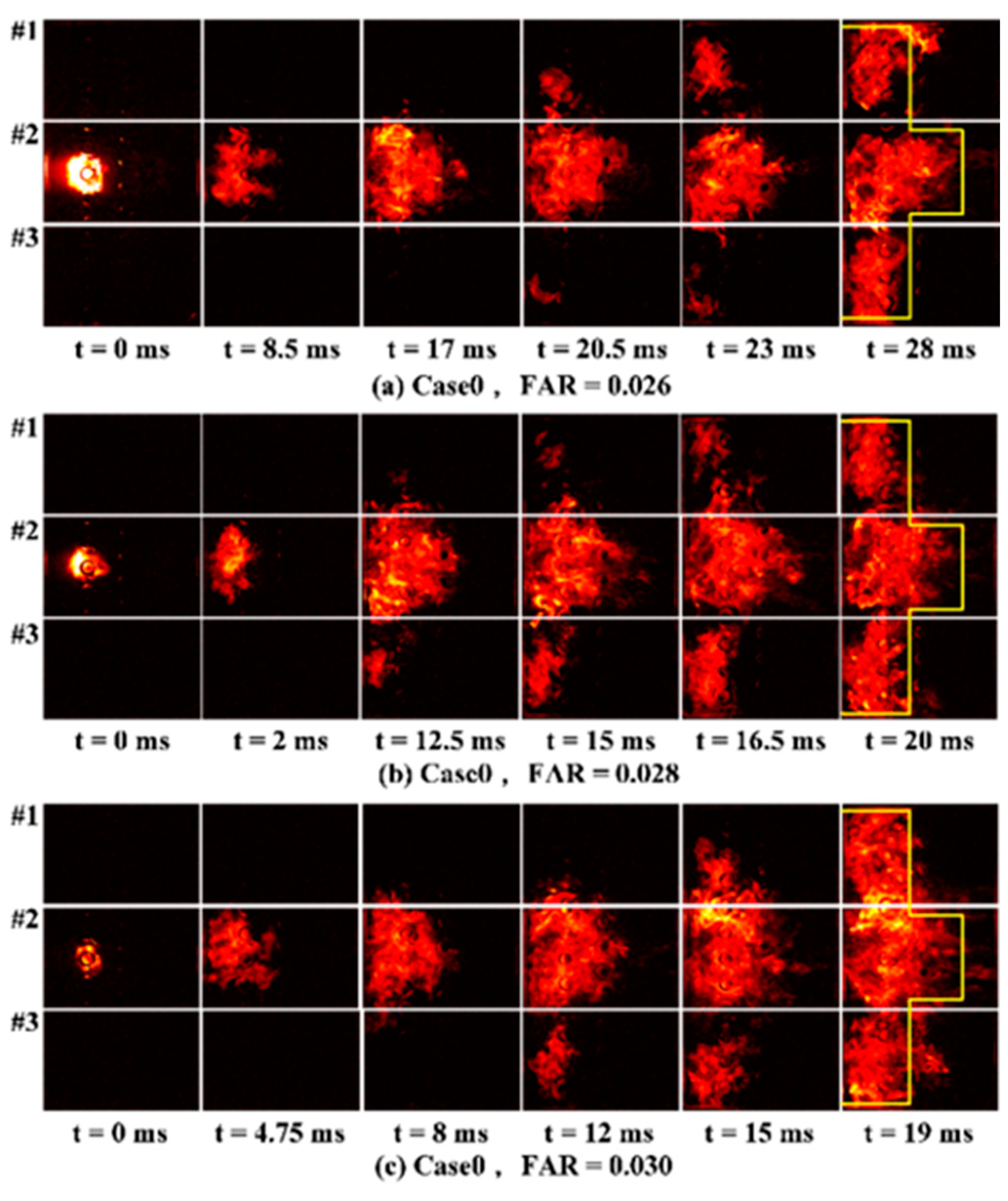
3.2.1. Turbine Guide Vane Fuel-to-Air Ratio Effect on the Light-Round Process

The time of ignition light-round and flame propagation process were measured for the schemes without guide vanes and with guide vane blockage ratios of 0.8, 0.7, and 0.6. The light-round time is defined as the time taken from the generation of the initial flame kernel to the complete ignition of the three domes. The experiments were carried out at three different fuel mass flow rates: 8.33, 8.97, and 9.61 kg/h, yielding fuel-to-air ratios from 0.026 to 0.030, as shown in Table 2.
The light-round times of the triple-dome combustor at different fuel-to-air ratios are shown in Figure 5. With an increase in the fuel-to-air ratio, the light-round time decreased for all the tested block ratios. In the meantime, the flame light-round time for the scheme without guide vanes was shorter than that for the scheme with guide vanes. The light-round time increased with the increase in the block ratio in the examined cases. To provide more details on the light-round process, the flame propagation process was imaged, as shown in Figure 6. Instantaneous flame propagation images during the light-round process of the triple-dome combustor without a guide vane under different fuel/air ratios.
Figure 6 shows the instantaneous flame propagation images during the light-round process of the triple-dome combustor under different fuel-to-air ratios from 0.026 to 0.030 for the scheme without guide vanes under the 0.089 kg/s inlet air mass flow rate. It can be found that as the fuel-to-air ratio increases, the time for the flame kernel to propagate to all three combustor domes becomes shorter. The light-round time under fuel/air ratios of 0.026, 0.028, and 0.030 are 28 ms, 20 ms, and 19 ms, respectively. This faster flame propagation can be attributed to the increased amount of fuel injected in the combustor, therefore increasing the local fuel-to-air ratio in the combustor. In the meantime, to increase the fuel injection amount, the fuel injection pressure also increased, therefore leading to improved fuel atomization, which enhanced flame ignition and propagation.
For the cases without guide vanes, the flame in the center dome propagated to the upper and lower domes nearly simultaneously, which contributed to a short light-round time in the scheme without guide vanes. After the completion of the light-round process, the flame from the middle dome #2 had already reached the outlet of the combustor, while the flames at the #1 and #3 domes had just been transferred to the vicinity of the dilution hole. The flame shape at the #1 and #3 domes appeared as a “convex” shape, as shown in Figure 6.
Figure 7 shows the instantaneous flame propagation images during the light-round process of the triple-dome combustor with guide vanes of 0.8 and 0.6 blockage ratio under fuel-to-air ratios from 0.026 to 0.030. The light-round process of the schemes with guide vanes of 0.8 blockage ratio under all the examined FAR showed a sequence in which the middle #2 dome ignited the upper #1 dome first, followed by the ignition of the lower dome (#3) by the #2 dome. Although the #1 dome ignited later than the #2 dome, the flame in the #1 dome showed higher flame propagation speed, therefore overtaking the flame in the #2 dome in the later stage of the flame propagation. At the end of the light-round process, the length of flame propagation was in the order of #1, #2, and #3.

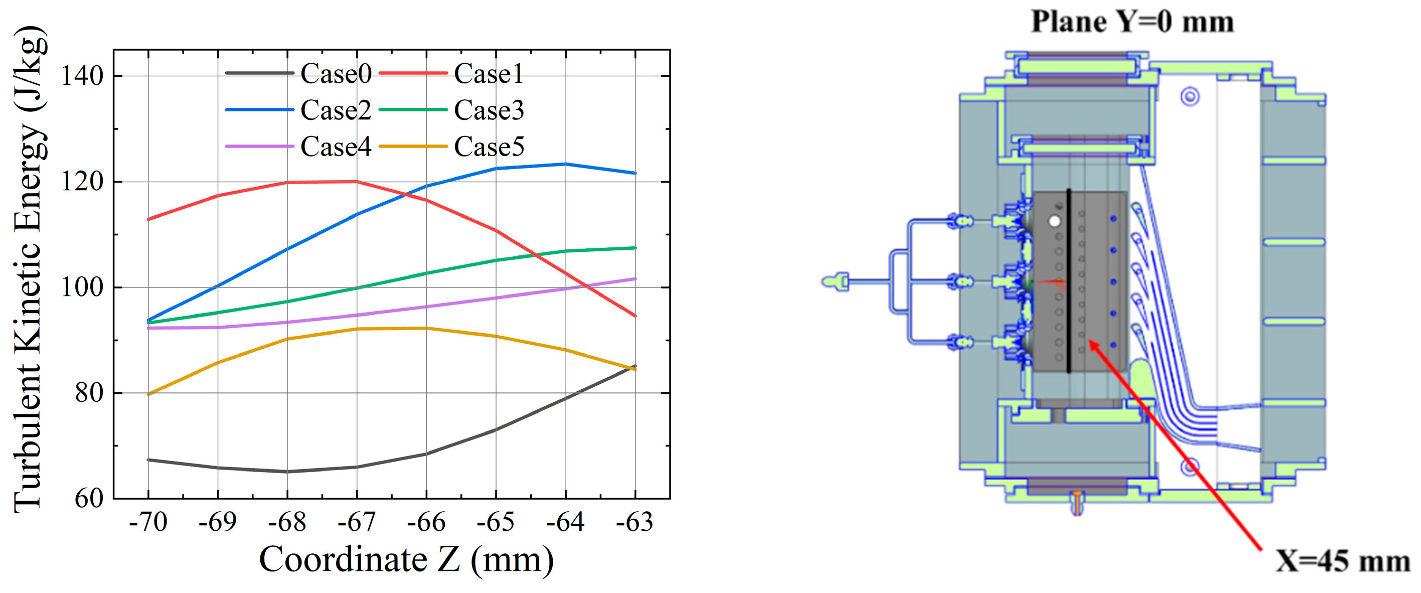
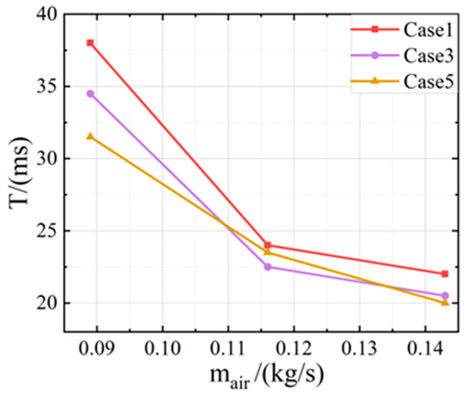
3.2.2. Mainstream Flow Rate Effect on the Light-Round Process

To study the mainstream flow rate effect on the light-round process, the combustor was operated under different mainstream mass flow rates from 0.089 to 0.143 with the fuel-to-air ratio (0.026) fixed, as shown in Table 3.
Figure 8 shows the comparison of the flame propagation time of the triple-dome combustor with different guide vane blockage ratios at various mainstream air mass flow rates. It can be observed that with an increase in the mainstream flow rate, the light-round time decreases for all the blockage ratios.
To further investigate the light-round process in the triple-dome combustor, the instantaneous flame propagation images were recorded at different mainstream flow rates and blockage ratios, as shown in Figure 9. It can be found that under the same mainstream air mass flow rate, the light-round process of the triple-dome combustor is essentially the same for different blockage ratios, as we observed in Figure 7. After being ignited by the igniter in the middle #2 dome, the flame propagated first toward the #1 dome; then, once its upper edge reached the upper wall of the combustor, the flame spread from the #2 dome toward the lower #3 dome, ultimately completing the light-round process.

4. Summary

This study focused on experimental investigations of ignition limits and light-round processes for a coupled setup of a triple-dome swirl combustor coupled with turbine guide vanes. Various scenarios were examined, including the presence or absence of turbine guide vanes and different guide vane blockage ratios. The fuel-to-air ratio and mainstream mass flow rate effects on the ignition were also examined. The main conclusions are as follows:
(1) The presence of a guide vane can increase the ignition performance of the triple-dome combustor; with the increase in the blockage ratio, the lowest ignition limit FAR under various mainstream air mass flow rates was achieved.
(2) The light-round time for both schemes with and without guide vanes decreases as the fuel-to-air ratio increases. Additionally, the light-round time increases with an increase in the blockage ratio. However, the scheme without guide vanes exhibits the shortest light-round time. The reason for the shorter light-round time in the scheme without guide vanes compared to the scheme with guide vanes lies in their different light-round processes. In the absence of guide vanes, the flame simultaneously propagates from the middle dome to the upper and lower domes, whereas in the presence of guide vanes, the flame from the middle dome propagates first towards the upper dome and then towards the lower dome, requiring relatively more time to establish a stable flame.
(3) When the fuel/air ratio remains constant, the light-round time decreases with the increase in incoming air mass flow rate.
However, this study primarily focused on specific parameter combinations and experimental conditions. Future research could explore a broader range of guide vane geometries and fuel types to further elucidate their effects on combustion chamber performance. Additionally, with advancements in numerical simulation technologies, the introduction of high-precision simulation tools combined with artificial intelligence algorithms holds promise for more accurate predictions of combustion processes in complex flow fields. Ultimately, these research findings could not only advance the optimization of aircraft engine design but also find applications in the field of new clean energy, laying a foundation for achieving more efficient and environmentally friendly combustion technologies.

Author Contributions

Investigation, Z.L., X.Z., K.W., F.L., C.R., J.Y., Y.M., C.L. and G.X.; Writing—original draft, Z.L.; Writing—review & editing, F.L. All authors have read and agreed to the published version of the manuscript.

Funding

This work was supported by the National Natural Science Foundation of China (No. 52276141) and the National Science and Technology Major Project (No. J2019-III-0006-0049). This work was supported by the Youth Innovation Promotion Association, the Chinese Academy of Science (No. Y2023043), and the Taishan Scholars Program.

Data Availability Statement

The original contributions presented in the study are included in the article, further inquiries can be directed to the corresponding author.

Conflicts of Interest

The authors declare no conflict of interest.

References

  1. Liu, D. The Development and Proposals of the Aeroengine Technology. Strateg. Study CAE 1999, 2, 24–29. [Google Scholar]
  2. Li, J.; Hu, Z. Design technology for high-temperature rise and high-heat capacity combustor. Gas Turbine Exp. Res. 2000, 13, 5–8. [Google Scholar]
  3. Escudier, M. Confined vortices in flow machinery. Annu. Rev. Fluid Mech. 1987, 19, 27–52. [Google Scholar] [CrossRef]
  4. Werschnik, H.; Hilgert, J.; Wilhelm, M.; Bruschewski, M.; Schiffer, H.-P. Influence of combustor swirl on endwall heat transfer and film cooling effectiveness at the large scale turbine rig. J. Turbomach. 2017, 139, 081007. [Google Scholar] [CrossRef]
  5. Aslanidou, I. Combustor and Turbine Aerothermal Interactions in Gas Turbines with Can Combustors. Ph.D Thesis, University of Oxford, Oxford, UK, 2016. [Google Scholar]
  6. Wang, G.; Xia, Y.; Ye, C.; Hu, K.; Linghu, C. Progress on light-round ignition dynamics in annular combustor. J. Exp. Fluid Mech. 2019, 33, 14–28. [Google Scholar]
  7. Ye, C.; Wang, G.; Fang, Y.; Ma, C. Ignition Dynamics in Annular Combustor with Turbine Guide Vanes. J. Combust. Sci. Technol. 2020, 26, 75–80. [Google Scholar]
  8. Wang, H.; Zhong, L.; Wang, G. Imaging Experiment Study of the Ignition Process in the Annular Combustion of Aero-engines. Adv. Aeronaut. Sci. Eng. 2019, 10, 861–866. [Google Scholar]
  9. Miki, K.; Moder, J.; Liou, M.S. Computational study of combustor–turbine interactions. J. Propuls. Power 2018, 34, 1529–1541. [Google Scholar] [CrossRef]
  10. Klapdor, E.V. Simulation of Combustor-Turbine Interaction in a Jet Engine. Ph.D. Thesis, Technische Universität Darmstadt, Darmstadt, Germany, 2011. [Google Scholar]
  11. Zhou, J.; Wan, P.-x.; Han, X.-s.; Mao, J.-k.; Bi, S.; Cai, K.-x. Very-Large Eddy Simulation of Turbulent Flow and Heat Transfer for Coupled Combustor-Turbine Components. J. Propuls. Technol. 2022, 43, 238–248. [Google Scholar]
  12. Wan, P.; Fan, J.; Han, X.; Mao, J. Very-large eddy simulation of impinging jet flow and heat transfer. J. Propuls. Technol. 2020, 41, 2237–2247. [Google Scholar]
  13. Machover, E.; Mastorakos, E. Spark ignition of annular non-premixed combustors. Exp. Therm. Fluid Sci. 2016, 73, 64–70. [Google Scholar] [CrossRef]
  14. Bach, E.; Kariuki, J.; Dawson, J.R.; Mastorakos, E.; Bauer, H.-J. Spark ignition of single bluff-body premixed flames and annular combustors. In Proceedings of the 51st AIAA Aerospace Sciences Meeting Including the New Horizons Forum and Aerospace Exposition, Grapevine, TX, USA, 7–10 January 2013; p. 1182. [Google Scholar]
  15. Barré, D.; Esclapez, L.; Cordier, M.; Riber, E.; Cuenot, B.; Staffelbach, G.; Renou, B.; Vandel, A.; Gicquel, L.Y.M.; Cabot, G. Flame propagation in aeronautical swirled multi-burners: Experimental and numerical investigation. Combust. Flame 2014, 161, 2387–2405. [Google Scholar] [CrossRef]
  16. Machover, E.; Mastorakos, E. Experimental investigation on spark ignition of annular premixed combustors. Combust. Flame 2017, 178, 148–157. [Google Scholar] [CrossRef]
  17. Mongia, H. Engineering aspects of complex gas turbine combustion mixers part I: High Delta-T. In Proceedings of the 49th AIAA Aerospace Sciences Meeting Including the New Horizons Forum and Aerospace Exposition, Orlando, FL, USA, 4–7 January 2011; p. 107. [Google Scholar]
  18. Philip, M.; Boileau, M.; Vicquelin, R.; Schmitt, T.; Durox, D.; Bourgouin, J.-F.; Candel, S. Simulation of the ignition process in an annular multiple-injector combustor and comparison with experiments. J. Eng. Gas Turbines Power 2015, 137, 031501. [Google Scholar] [CrossRef]
  19. Philip, M.; Boileau, M.; Vicquelin, R.; Schmitt, T.; Durox, D.; Bourgouin, J.-F.; Candel, S. Ignition sequence of an annular multi-injector combustor. Phys. Fluids 2014, 26, 091106. [Google Scholar] [CrossRef]
  20. Philip, M.; Boileau, M.; Vicquelin, R.; Riber, E.; Schmitt, T.; Cuenot, B.; Durox, D.; Candel, S. Large eddy simulations of the ignition sequence of an annular multiple-injector combustor. Proc. Combust. Inst. 2015, 35, 3159–3166. [Google Scholar] [CrossRef]
Figure 1. Diagram of Experimental System.
Energies 17 04636 g001
Figure 2. The details of the triple-dome combustor coupled with turbine guide vanes.
Energies 17 04636 g002
Figure 3. The ignition limits under different air mass flow rates for the triple-dome combustor with six operating conditions.
Energies 17 04636 g003
Figure 4. The turbulent kinetic energy for the triple-dome combustor with six operating conditions at X = 45 mm.
Energies 17 04636 g004
Figure 5. Light-round time of triple-dome combustor under different fuel/air ratios for baseline case and case 1, 3, and 5.
Energies 17 04636 g005
Figure 6. Instantaneous flame propagation images during the light-round process of the triple-dome combustor without guide vanes under different fuel/air ratios.
Energies 17 04636 g006
Figure 7. Instantaneous flame propagation images during the light-round process of the triple-dome combustor with guide vane of 0.8 and 0.6 blockage ratio under different fuel/air ratios.
Energies 17 04636 g007
Figure 8. Light-round time of triple-dome combustor of different guide vane blockage ratios under different mainstream air mass flow rates.
Energies 17 04636 g008
Figure 9. Instantaneous flame propagation images during the light-round process of the triple-dome combustor with guide vane of 0.8, 0.7, and 0.6 blockage ratios under 0.116 kg/s and 0.143 kg/s mainstream air flow rate.
Energies 17 04636 g009
Table 1. Test guide vane scheme.
SchemeTurbine GuideBlockage
Case0No0.00
Case1Yes0.80
Case2Yes0.75
Case3Yes0.70
Case4Yes0.65
Case5Yes0.60
Table 2. Light-round experimental conditions with and without turbine guide vane schemes.
mair/(kg/s)mfuel/(kg/h)Fuel-to-Air Ratio
0.0898.330.026
0.0898.970.028
0.0899.610.030
Table 3. Experiment conditions under different mainstream flow rates.
mair/(kg/s)mfuel/(kg/h)Fuel-to-Air Ratio
0.0898.330.026
0.11610.860.026
0.14313.380.026
Disclaimer/Publisher’s Note: The statements, opinions and data contained in all publications are solely those of the individual author(s) and contributor(s) and not of MDPI and/or the editor(s). MDPI and/or the editor(s) disclaim responsibility for any injury to people or property resulting from any ideas, methods, instructions or products referred to in the content.

