Article

Experimental Investigations into a Hybrid Energy Storage System Using Directly Connected Lead-Acid and Li-Ion Batteries

by
Andrei Dascalu
,
Andrew J. Cruden
and
Suleiman M. Sharkh
*
Mechanical Engineering, University of Southampton, Highfield Campus, Southampton SO17 1BJ, UK
*
Author to whom correspondence should be addressed.
Energies 2024, 17(18), 4726; https://doi.org/10.3390/en17184726
Submission received: 29 July 2024 / Revised: 28 August 2024 / Accepted: 31 August 2024 / Published: 23 September 2024
(This article belongs to the Section D: Energy Storage and Application)

Abstract

:
This paper presents experimental investigations into a hybrid energy storage system comprising directly parallel connected lead-acid and lithium batteries. This is achieved by the charge and discharge cycling of five hybrid battery configurations at rates of 0.2–1C, with a 10–50% depth of discharge (DoD) at 24 V and one at 48 V. The resulting data include the overall round-trip efficiency, transient currents, energy transfers between the strings, and the amount of energy discharged by each string across all systems. The general observation is that the round-trip efficiency drops from a maximum of around 94–95% in the first stages of the charge/discharge process, when only the Li-ion strings are active, to around 82–90% when the lead-acid strings reach a DoD of up to 50%. The most important parameters in the round-trip efficiency function are the ratio between the Li-ion and lead-acid energy available and the charge/discharge current. The energy transfer between the strings, caused by the transient currents, is negligible in the first stages of the discharge and then grows, with the DoD peaking at around 60% DoD. Finally, during the first stage of discharge, when only the Li-ion strings are active, the amount of energy discharged varies with the discharge C rate, decreasing to almost half at between 0.2 and 1C.

1. Introduction

In 1990, 80% of the total world energy demand was provided by fossil fuels and, despite all efforts, this is still the case today. The growth of renewables has been mirrored by an increase in the consumption of fossil fuels [1]. The positive side of this story is that substantial decarbonization progress has been made in the worldwide power sector. Including hydropower, by 2021, around a third of global power generation came from renewables. This is an increase from just 12% in 1990 [2]. The main reason for this is the dramatic fall in renewable power generation costs. Analyses in the REN21 and IRENA [2,3] reports show that in the last decade, before the current anomalies in the energy markets, the global average of the levelized cost of electricity produced by utility-scale PV dropped by 85%, from USD 0.38/kWh in 2010 to USD 0.057/kWh in 2020. Residential PV electricity cost decreased between 50% and 80% in the same period, dropping to around USD 0.055–0.236/kWh. Onshore and offshore wind also decreased by 56% and 48% to around USD 0.039/kWh and USD 0.084/kWh, respectively. Although dwarfed by PV and wind in terms of global capacity growth, the electricity cost of CSP also decreased by 68% in the last decade, reaching an average of USD 0.108/kWh. These figures show a growing share of variable renewable generators being connected to power systems worldwide. This is only going to accelerate in the next decades with the electrification of heat and transport. For example, in the UK, studies like Ref. [4] estimate that the total electricity consumption could double by 2050. However, running national and continental power grids with a large share of variable power generators introduces technical, operational, and economic challenges that can be solved by addressing the problem of electricity storage.
Comprehensive reviews like Refs. [5,6] have compiled dozens of research studies that estimate the energy storage requirements for grids with a high share of variable renewables. It is very difficult to calculate the exact electricity storage requirements because each country has different wind and solar profiles, as well as different hydropower potential, but a general picture emerges of more variable renewables and more storage. A generic power grid with a share of 10–70% variable renewables has relatively low energy storage requirements, below 25% of the maximum power demand (in GW) and below 0.1% of the total yearly electricity consumption (in GWh). However, some studies show that this low limit increases to 75% of the maximum GW grid demand and to around 1% of total yearly electricity consumption for 100% variable renewable grids. For the UK grid, taking into account interconnectors, renewables over-generation, nuclear power, and demand management, studies like Ref. [7] estimate that around 46 GW of storage is required for zero-carbon electricity, half of which should be long-term storage for over 4 h and up to weeks and months. The UK has around 4 GW of electrical storage installed, around 2.9 GW/26.7 GWh being pumped hydro and 1.1–1.3 GW battery storage with 1–2 h discharge duration [8]. Currently, the UK has one of the fastest-growing utility battery storage markets: “As of June 2023, the UK has more than 2.4 GW of installed battery storage capacity and a total pipeline of planned capacity exceeding 66 GW” [9]. Aurora [7] estimates that around 24 GW of storage with 1–4 h duration, generally covered by batteries, will be required for net-zero grid electricity. The above figures show that energy storage and, especially, utility battery storage are already playing a significant role in the electric power sector and their role will only increase.

1.1. Hybrid Battery Storage Systems

One specific area of electrical energy storage is hybrid storage systems. The literature is vast on the hybridisation possibilities, which include dozens of hybrid energy storage options [10,11,12,13]. The main reason why hybrid options are being considered in the literature is that each energy storage technology type performs differently in terms of its power and energy characteristics. Review articles like Refs. [10,14,15] list multiple categories of storage technologies that can provide high-power or high-energy capacity. Generally, high-power devices have hundreds of thousands of operating cycles, high round-trip efficiencies, and long operating life but also have low energy capacity and density. For example, supercapacitors have four times the power density of Li-ion batteries, can deliver more than 1 million cycles but have around 50 times less energy density than the average Li-ion chemistries [16]. Conversely, high-energy storage systems have high energy density but a lower cycle life and round-trip efficiency and a slower response time. Examples of these include a long list of various battery technologies like NaS, Li-ion, and flow batteries, as well as thermal storage technologies [17].
Complementary characteristics between high-power storage and high-energy technologies can be used to enhance the performance of energy storage systems using hybrid arrangements. The benefits of this are numerous, including an improved lifespan, cost reduction, and power quality improvements. For example, in Ref. [18], a hybrid arrangement of Li-ion batteries and flywheels acting as high-power and high-energy devices, respectively, is analysed. The results show that the flywheels reduce the stress on the battery. This was quantified as an improvement in battery life by more than 20%. Studies like Ref. [19] show a cost reduction by hybridising battery packs.

1.2. Dual-Chemistry Energy Storage System

An attractive grid energy storage option involves the hybridisation of different types of batteries. The idea is similar to other general hybrid storage options: high-power, high-cycle-life batteries can be linked with other chemistry types to obtain an improved system overall. There are multiple case studies on this system set-up around the world; for example, in the UK, the hybrid battery solution for the Energy Superhub Oxford uses 2 MW of vanadium flow batteries for heavy cycling and 50 MW of Li-ion system for longer-duration loads [20]. A similar solution can be found in Braderup, Germany, where 2 MW/2 MWh Li-ion batteries have been linked with 325 kW/1 MWh vanadium flow batteries to support a local wind farm [21,22]. The 5 MW/5.4 MWh M5BBAT project in Achen, Germany uses five types of battery: 2 MW of two lead-acid battery types, 180 kW of Na-NiCl2 batteries, and 2.8 MW of Li-ion (LFP) batteries [23,24]. In Varel, Niedersachsen, Germany, Hitachi developed an 11.5 MW/22.5 MWh hybrid Li-ion and sodium sulphur (NaS) storage solution, with Li-ion being used as the high-power component for frequent cycling and NaS acting as the high-energy component [25]. The largest hybrid battery in Poland, in Gdansk, uses 5 MW of lead-acid and 1 MW of Li-ion batteries to provide a total of 27 MWh capacity to smooth the output of the Bystra wind farm [26]. Elsewhere, Hoppecke installed hybrid lead-acid and Li-ion solutions at all scales [27]. In Ref. [28], Hitachi presents a lead-acid and Li-ion hybrid system for grid applications and discusses its sizing principles. GS Yuasa has also developed Li-ion and lead-acid hybrid systems for R&D purposes or EV charging station applications [29,30]. The German company BOSS has developed a small-scale directly parallel connected lead-acid and Li-ion hybrid system (LE300—Smart Battery System) [31]. The BOSS storage system has successfully been used in academic studies for micro-grid optimisation [32,33,34]. Khazali et al. 2024, showed that hybrid Li-ion and lead-acid BESS systems could be up to 21% lower when compared with single Li-ion storage systems [35]. Other studies on the subject are discussed in Refs. [36,37].
This paper considers the directly parallel connected lead-acid and Li-ion hybrid system option. The arguments for this decision are centred on three main points: a simple hybrid architecture, sizing flexibility, and economics. Firstly, hybrid storage systems are associated with complicated architectures; almost all the developments of hybrid systems presented above need additional power electronic equipment and control systems when compared with single-type storage. This adds extra cost because the power electronics associated with battery storage systems can be as high as 30% of the total CAPEX. A typical cost breakdown for battery storage units is around 40% for the cell cost and 30% for the peripherals, like power electronics equipment and cables [38]. However, directly connected lead-acid and Li-ion systems can operate at similar voltage ranges with high-voltage packs. This implies that the system can work within certain limits using passive components, thus eliminating the extra cost of the power converters associated with hybrid systems [13]. Secondly, hybrid arrangements have more flexibility in terms of system size. For lead–lithium hybrid systems, the lead-acid battery can cover the base of the load curves and the Li-ion battery can be optimised to supply load peaks. In this way, we do not oversize the system by utilizing high-performance chemistry when this is not really needed. The third advantage of lead–lithium systems is economics. Studies like Refs. [36,39,40] show that overall, the lead and lithium hybrid system can offer cost reductions. Additionally, lead-acid batteries are easily recyclable, and this provides the circular economics for a sustainable industry. The disadvantages of hybrid battery systems using passive architectures are limited power-sharing control and the large transient circulating currents between battery strings during the rest periods.
There are a few general studies published on directly parallel connected Li-ion and lead-acid systems. In Ref. [41], the authors develop a simple model for a directly connected lead-acid and Li-ion hybrid system for general design purposes. Papers like Refs. [42,43] discuss the behaviour of directly connected lead-lithium DC-linked systems for telecommunication applications. However, there is a gap in the literature in terms of actual performance data and detailed analysis and the modelling of these hybrid batteries.
This paper presents experimental investigations into a hybrid energy storage system comprising directly parallel connected lead-acid and lithium batteries. This is achieved by the charge and discharge cycling of a number of battery configurations at different rates and by measuring their overall round-trip efficiency, transient currents, energy transfers between the strings, and the amount of energy discharged by each string across all systems.

2. Materials and Methods

Several hybrid battery systems of different configurations were tested using GS Yuasa LEV50 Li-ion cells and SWL3300 lead-acid batteries. The main technical characteristics of the cells and batteries used in the experiments are shown in Figure 1 and Table 1.
The test equipment used in this research comprises EA ELEKTRO-AUTOMATIK products, the EA-PSI 9080-510 power supply, and the EA-EL 9080A electronic load. The programmable load and the power supply are equipped with internal data-logging options and load profile customization possibilities. The discharge profile can be loaded onto the machines using Microsoft Excel Office 365 spreadsheets and the recorded data can be stored on a standard PC in Excel format. The data transfer between the electronic load/power supply and the data logging laptop is achieved via a USB connection, using a specialized interface card. The equipment can be used in various modes but, for this project, only the ‘battery mode’ has been used. An overview of the testing arrangement is shown in Figure 2.
Figure 3 shows a schematic diagram of the test setup. On top of the internal data-logging capabilities of the load and power supply, an additional data acquisition system has been installed to make it possible to collect data over the internet, as indicated. The switching system allows different hybrid battery configurations in terms of the number of strings of each chemistry. The choice of the number of cells or batteries of each type is such that the Li-ion open circuit is higher than the lead-acid, as illustrated in Figure 4; as a result, the Li-ion battery discharges more frequently, with the lead-acid battery being kept in reserve, which reduces the degradation of the latter.
The following systems have been tested using the experimental arrangement indicated in Figure 3:
  • Hybrid System 1: 2LI&1LA (24 V)—Two strings of Li-ion and one of lead-acid at 24 V. Switches S5, S6, and S4 are closed, and S2 and S3 are opened. The power supply and electronic load switches are kept closed all the time.
  • Hybrid System 2: 1LI&1LA (24 V)—One string of Li-ion and one of lead-acid. Switches S5 and S2 are closed, along with the power supply and electronic load, and S3, S4, and S6 are opened.
  • Hybrid System 3: 1LI&2LA (24 V)—One string of Li-ion and two lead-acid strings at 24V. Switches S5, S2, and S3 are closed and S4 is opened.
  • Hybrid System 4: 1LI&3LA (24 V)—One string of Li-ion and three strings of lead-acid at 24V. Switches S2, S3, S4, and S5 are closed and S6 is opened.
  • Hybrid System 5: 1LI&1LA (48 V)—Hybrid system at 48 V using one Li-ion string and one lead-acid string.
The focus of the present paper is to experimentally determine the performance of directly parallel connected hybrid Li-ion and lead-acid systems in various parallel configurations. This has been achieved by analysing the following parameters: energy (kWh) and charge (Ah), being charged/discharged as a function of the charge/discharge rate, the depth of discharge, and the number of strings of each chemistry form; the hybrid system round-trip efficiency as a function of the DoD, charge/discharge rate, and the number of lead-acid and Li-ion strings operating in parallel.
The testing procedure is as follows:
  • Link the Li-ion and lead-acid strings and let the system rest for 3–5 h at room temperature or until the system reaches equilibrium.
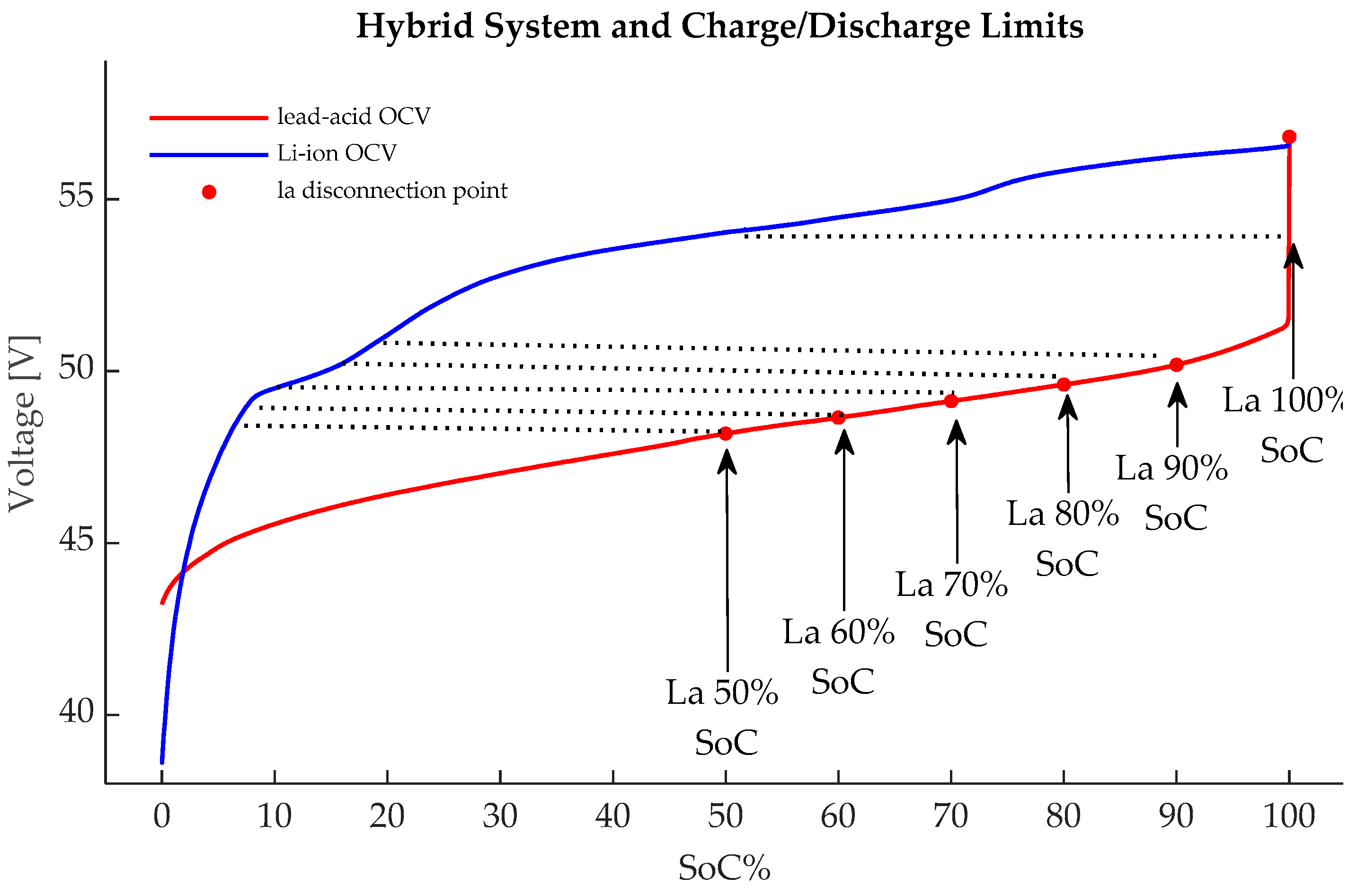
  • Cycle the system between 100% SoC, for both strings, and various SoC percentages for the lead-acid string. Since the Li-ion string discharges first, the disconnection point is set by the minimum voltage allowed by the lead-acid strings. To avoid rapid degradation, the lead-acid strings were kept above 50% SoC. The cycling intervals are as follows (see Figure 4):
    a.
    Cycling Range 1: charge/discharge of the hybrid system from 100% SoC (both Li-ion and lead-acid strings at 100% SoC and at a system voltage of 28.1 V) and discharge to 2.25 V/cell for the lead-acid cells, corresponding to a 100% lead-acid SoC.
    b.
    Cycling Range 2: charge/discharge of the hybrid system from 100% SoC (both Li-ion and lead-acid strings at 100% SoC and at a system voltage of 28.1 V) and discharge to 2.091 V/cell for the lead-acid cells, corresponding to a 90% lead-acid SoC.
    c.
    Cycling Range 3: charge/discharge of the hybrid system from 100% SoC (both Li-ion and lead-acid strings at 100% SoC and at a system voltage of 28.1 V) discharge to 2.067 V/cell for the lead-acid cells, corresponding to an 80% lead-acid SoC.
    d.
    Cycling Range 4: charge/discharge of the hybrid system from 100% SoC (both Li-ion and lead-acid strings at 100% SoC and at a system voltage of 28.1 V) discharge to 2.047 V/cell for the lead-acid cells, corresponding to a 70% lead-acid SoC.
    e.
    Cycling Range 5: charge/discharge of the hybrid system from 100% SoC (both Li-ion and lead-acid strings at 100% SoC and at a system voltage of 28.1 V) discharge to 2.027 V/cell for the lead-acid cells, corresponding to a 60% lead-acid SoC.
    f.
    Cycling Range 6: charge/discharge of the hybrid system from 100% SoC (both Li-ion and lead-acid strings at 100% SoC and at a system voltage of 28.1 V) discharge to 2 V/cell for the lead-acid cells, corresponding to a 50% lead-acid SoC.
  • Let the system rest for 3–6 h until the circulation currents between the strings become negligible.
  • Record the currents ILi-ion and Ilead-acid indicated in Figure 3, as well as the system voltage every second.
  • Repeat the steps above for the different C rates, with 0.2–1C for the lead and lithium configurations indicated. The C rate of the hybrid system is dictated by the lowest C rate sum between the two chemistries. Increasing the lead-acid strings does not automatically mean increasing the maximum discharge current for the whole system, as this might be limited by the Li-ion bank. For the 1LI&1LA system, for example, the 1C rate is 50 A, the same as the 1C rate of one Li-ion string, which is lower that the 1C rate of the lead-acid (100 Ah at 0.1C). Again, for the 2LI&1LA system, the current is limited by the Li-ion battery strings to 100 A at the 1C rate.

3. Results

The typical charge and discharge voltages and current waveforms of a 24 V hybrid battery configuration are shown in Figure 5. When discharging, the current is supplied mainly by the Li-ion battery during interval A–B. At point X, the two batteries share the constant total current equally. At C, the lead-acid battery takes over and supplies most of the current. When the discharge stops, at D, a decaying circulating current flows from the lead-acid battery to the Li-ion battery.
When charging, the Li-ion battery takes a larger share of the current initially, during the A–B interval. At B, the lead-acid battery takes over and draws more current. Towards the end of the constant-current charging period (A-D), at point C, the Li-ion battery takes over again and draws more current. After the constant-current charging period stops at D, the voltage is kept constant while the charging current in both batteries decays.
The following parameters were extracted from the waveforms:
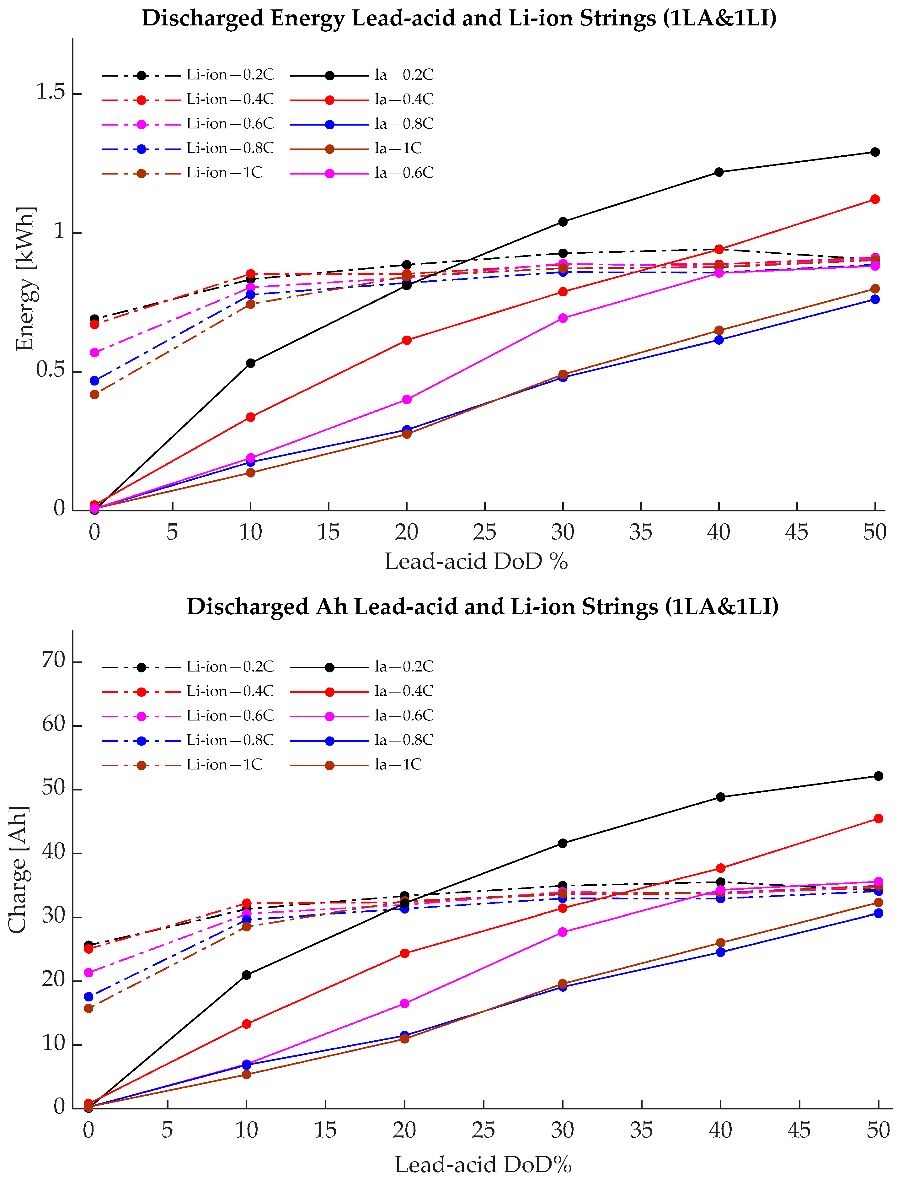
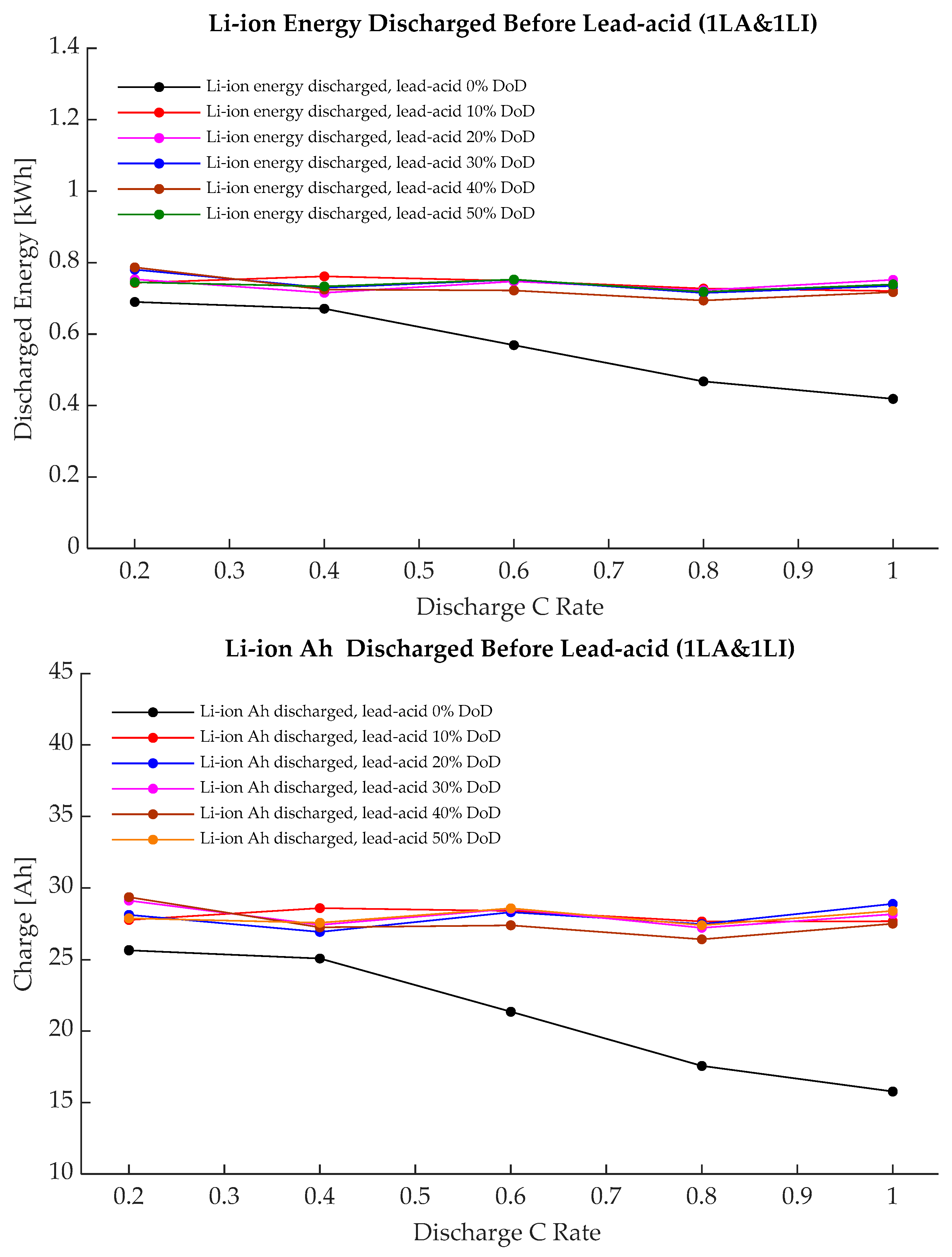
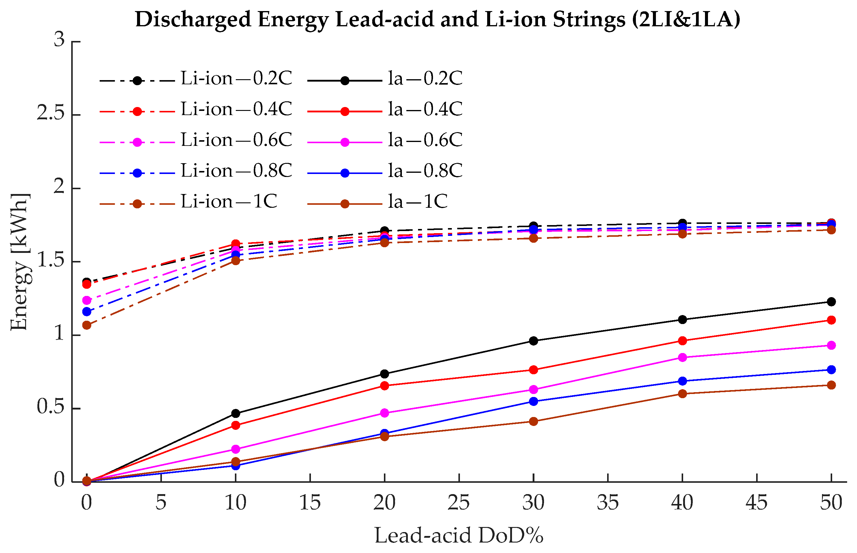
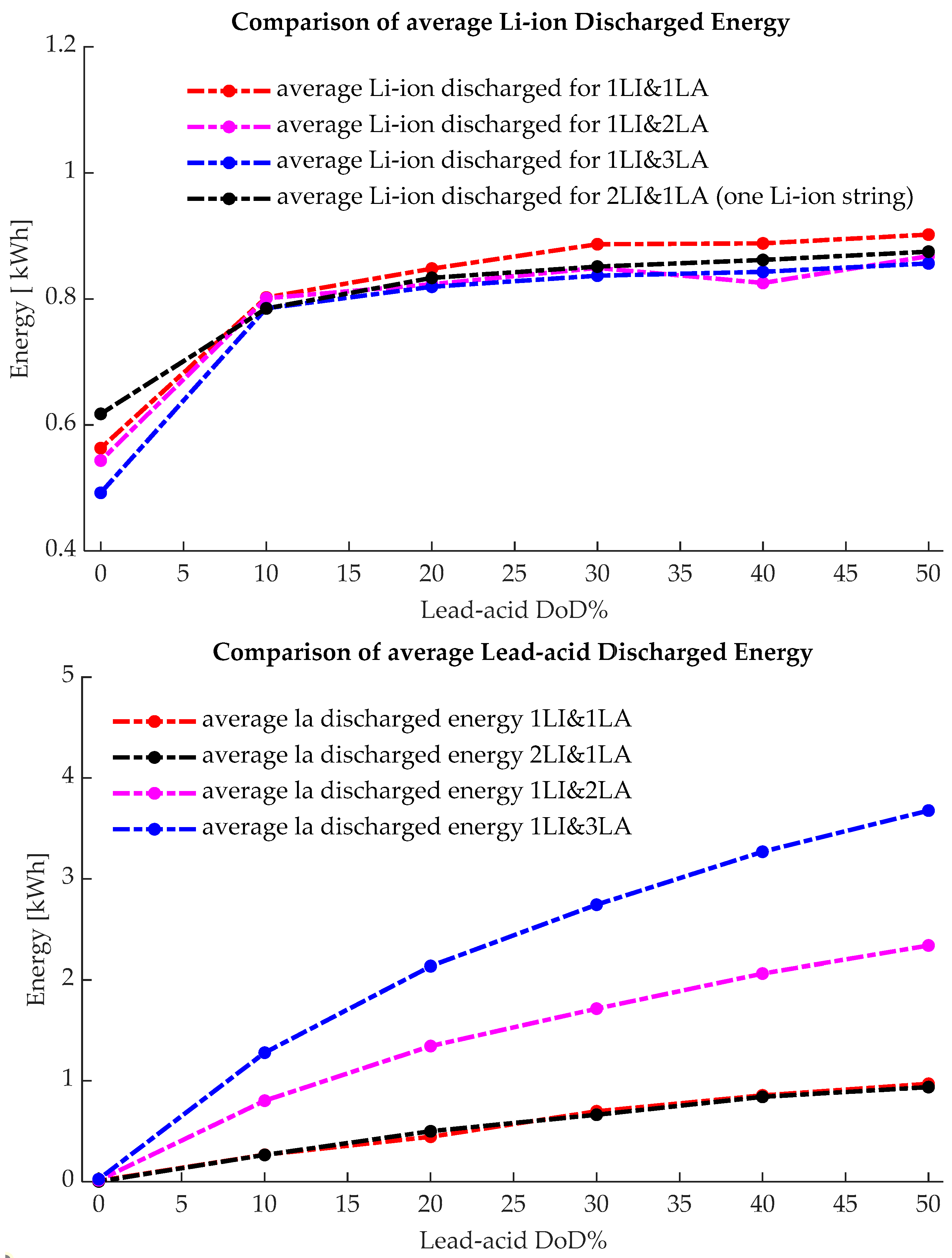
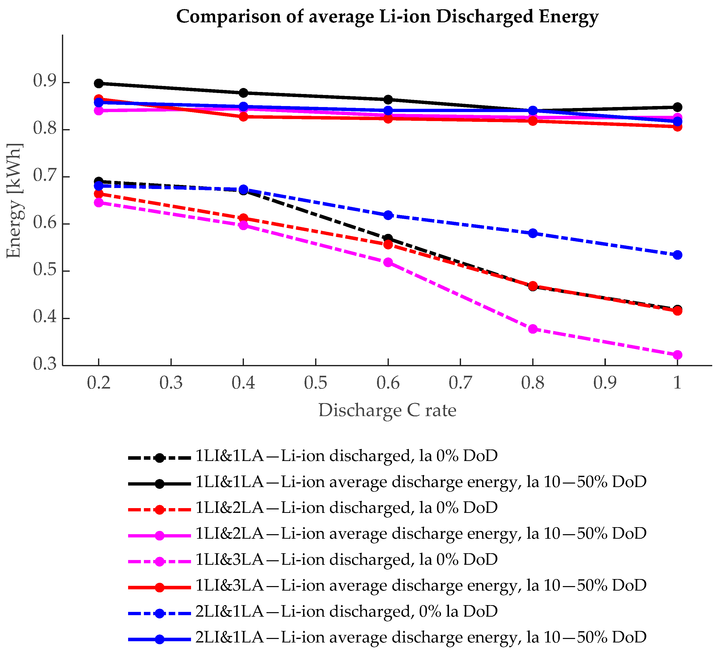
  • The energy (kWh) and charge (Ah), charged/discharged as a function of the charge/discharge rate, the depth of discharge, and the number of strings of each chemistry.
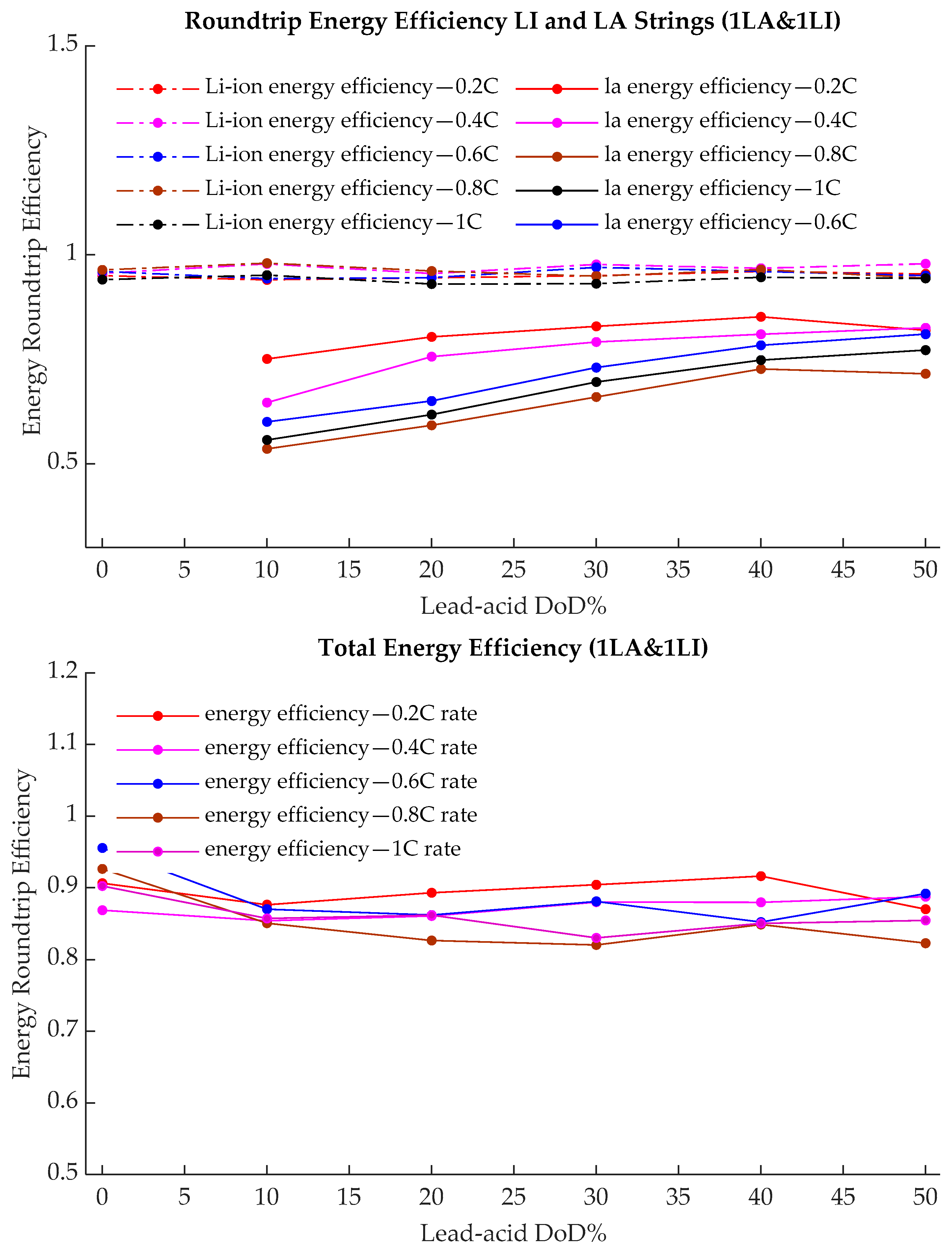
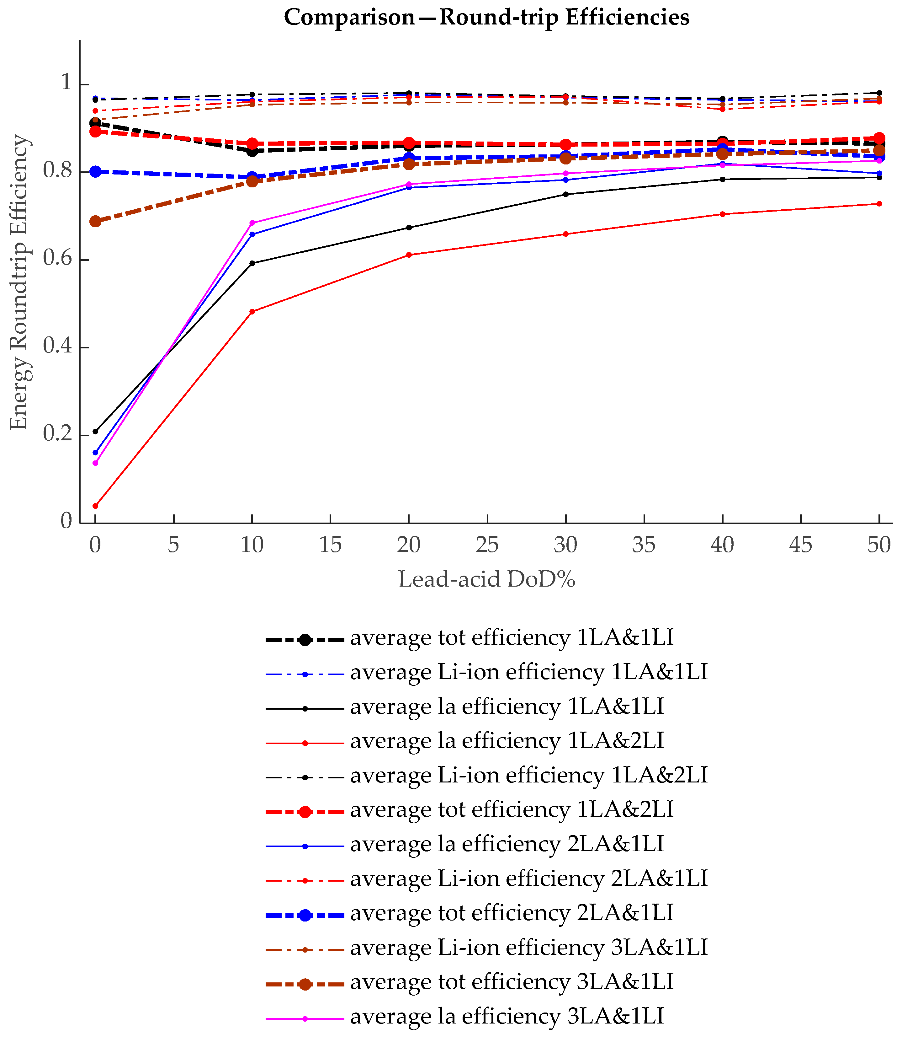
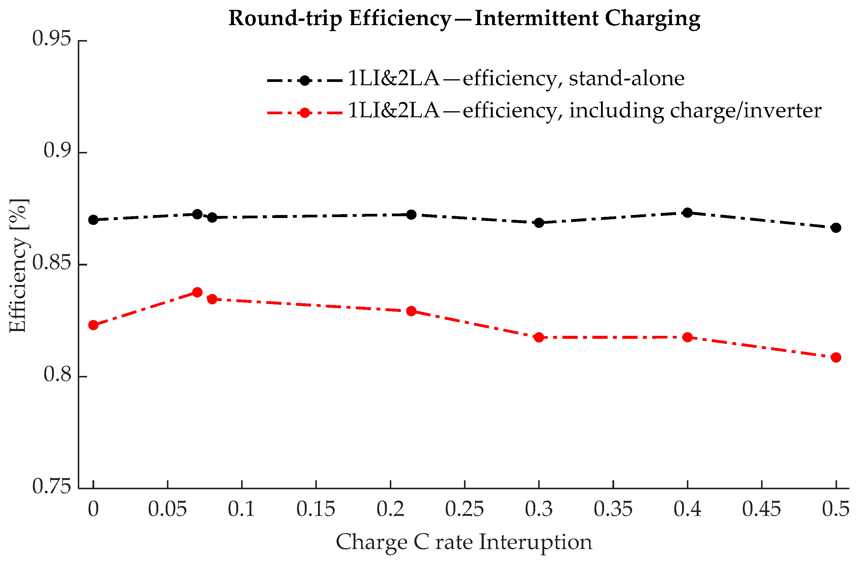
  • The hybrid system’s round-trip efficiency as a function of the depth of discharge (DoD), the charge/discharge rate, and the number of lead-acid and Li-ion strings operating in parallel.
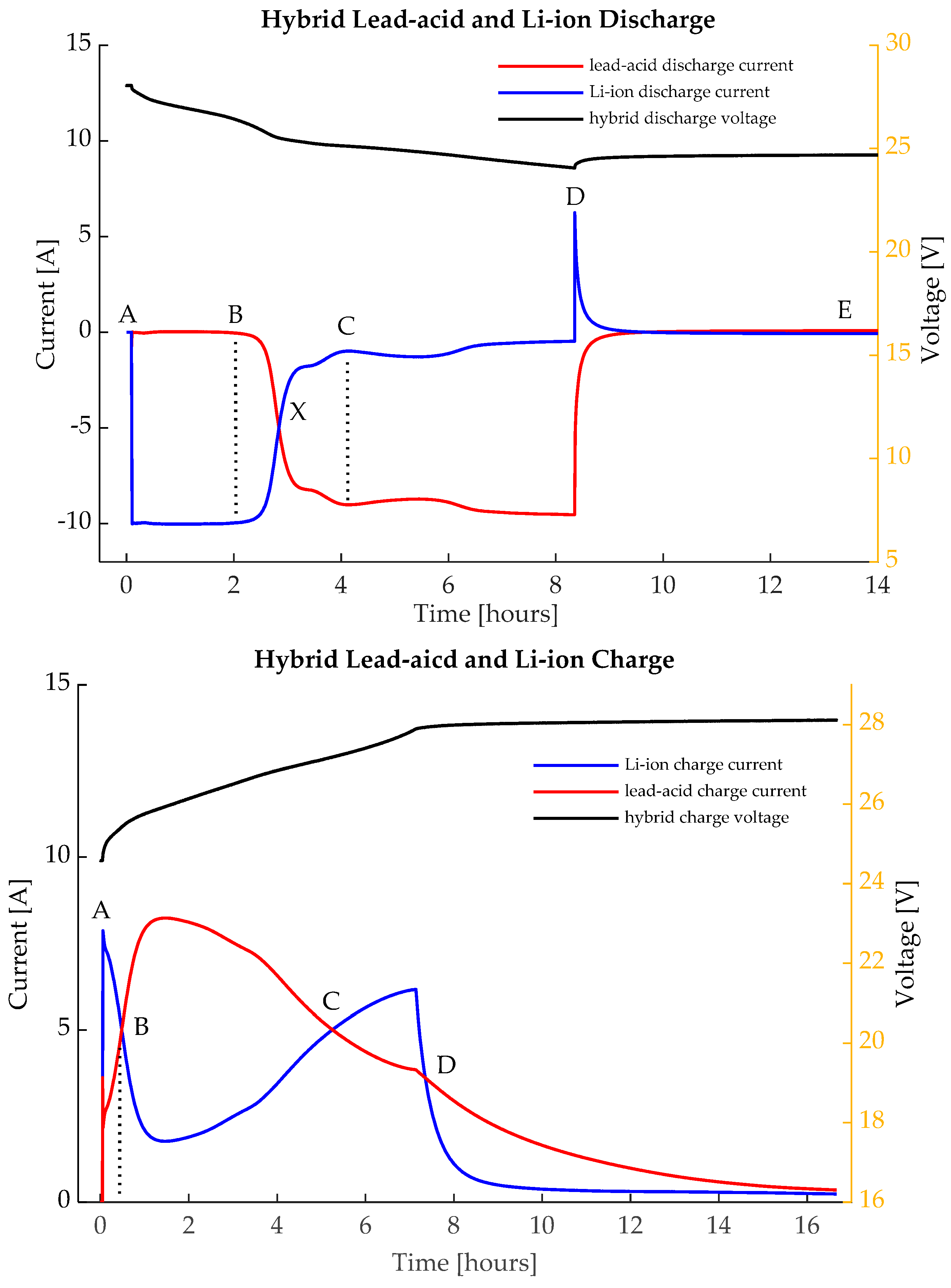
  • The Li-ion DoD, before the currents delivered by both chemistry strings become equal between points A and B and between A and X in Figure 5, as a function of the discharge rate and the hybrid configuration.
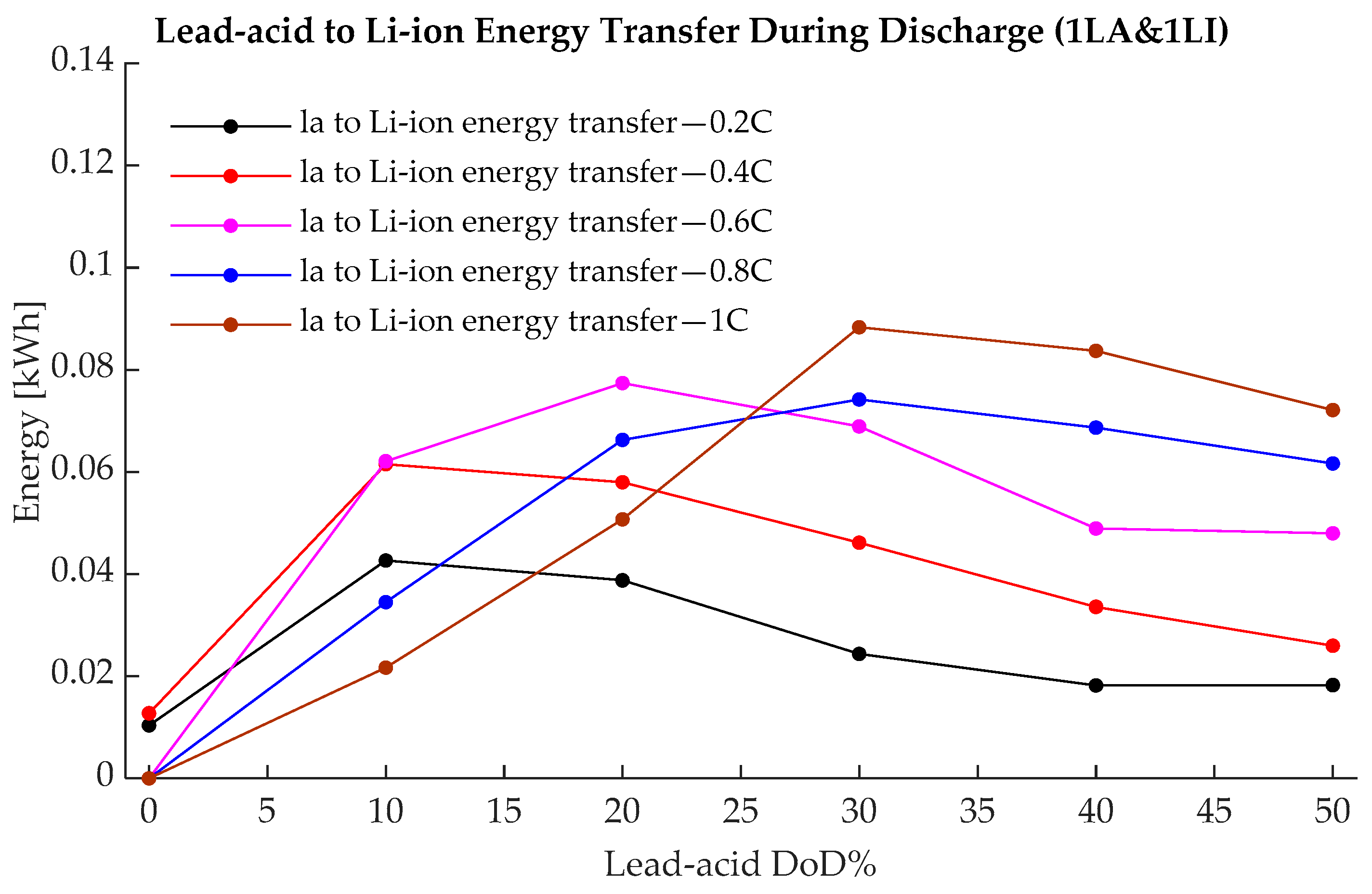
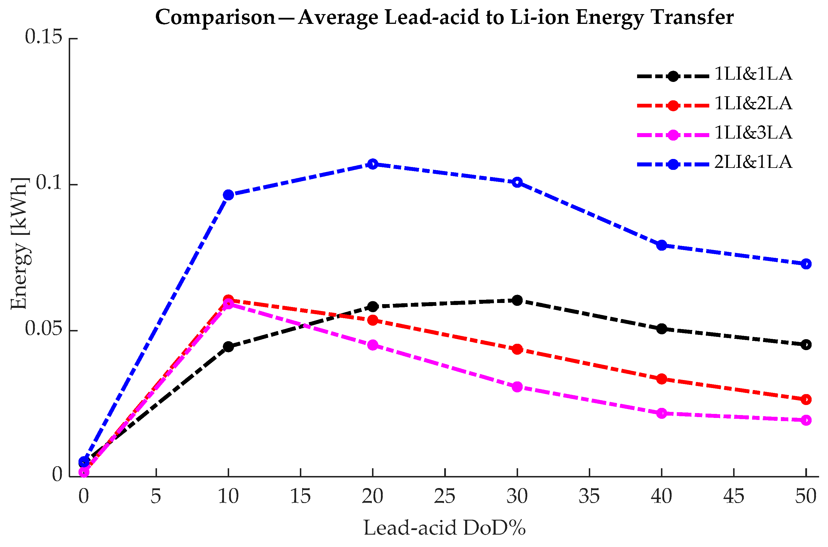
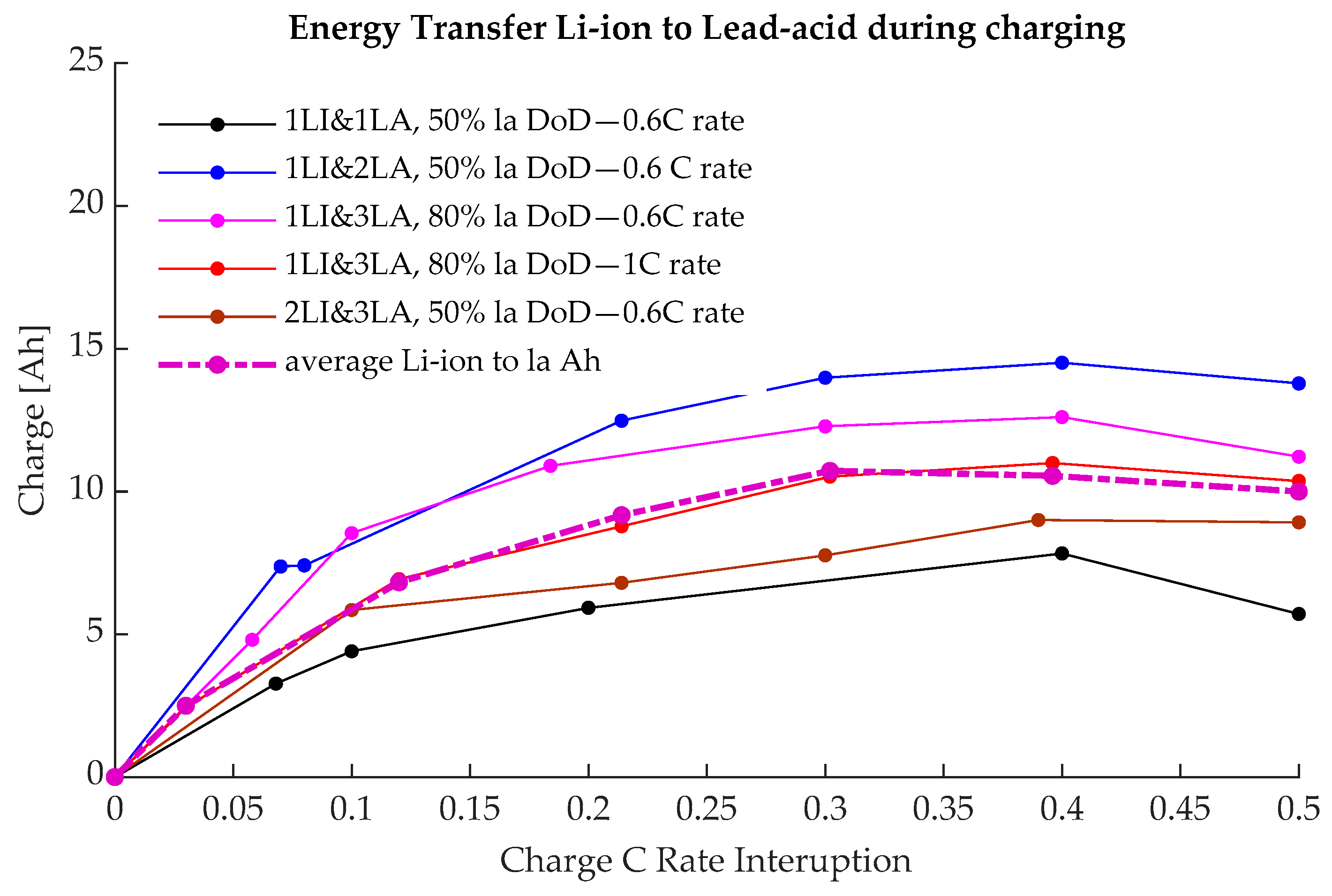
  • The energy and charge transfer between the strings, and between points D and E at the end of discharge, as a function of the lead-acid battery’s depth of discharge, discharge current, and system configuration.

3.1. Hybrid System 24 V, 1 Li-ion String, and 1 Lead-Acid (1LI&1LA)

The first arrangement analysed here is a 24 V hybrid system with only two strings, one for each chemistry type. The system was cycled between states at the charge intervals indicated in the previous section. Because in normal operating conditions, the hybrid system will never be fully discharged, the lead-acid strings were kept above 50% DoD, and all the analysis is in reference to this.
Figure 6 shows the total energy and amp-hours discharged by each system string as a function of the discharge rate and the lead-acid battery’s depth of discharge. This shows that the total energy and charge available within the same operating voltage range of the hybrid system depend on the charge/discharge C rate. This is mainly because the charge and energy available from the lead-acid string are dictated by Peukert’s law. When only the Li-ion battery is cycled, the total available charge and energy are dictated by the internal resistance of the Li-ion strings. For example, during cycling range 1, when only the Li-ion string is cycled, and the lead-acid battery is kept fully charged at 0% DoD, the total available energy ranges from 0.418 to 0.689 kWh for the 1 to 0.2C rates, respectively, as shown in Figure 6 (top). The corresponding amp-hours range from 15.765 Ah to 24.6 Ah. For the following five cycling ranges, when the lead-acid string is discharged to 10–50% DoD (cycling range 2 to 6, Section 3), the Li-ion battery’s discharged energy slowly rises to a maximum of 0.91 kWh, which corresponds to 34.9 Ah, when the hybrid strings are discharged to 50% DoD.
This finding shows that in the normal operating conditions of the hybrid system, most of the Li-ion battery’s energy capacity is available for cycling independently of the lead-acid string cycling. When the 1LI&1LA system is charged/discharged at 0.2C, a maximum of 75–76% of the available Li-ion energy [kWh] or charge [Ah] can be cycled independently for frequent charge/discharge cycles, keeping the lead-acid strings at a 100% SoC. This drops to 45–46% if the system is charged/discharged at 1C.
A total energy capacity of 2.201 kWh is available from the 1LI&1LA hybrid system when the arrangement is discharged at low C rates (0.2C for the analysed case). This includes 0.91 kWh delivered by the Li-ion strings and 1.291 kWh delivered by the lead-acid battery. The same figure drops to a total of 1.695 kWh for the 1C charge/discharge rates, with 0.91 kWh from the Li-ion string and 0.785 kWh from the lead-acid chemistry. As explained earlier, this is due to less energy and charge being available from the lead-acid string according to Peukert’s law.
Figure 7 shows the energy [kWh] and charge [Ah] discharged from the Li-ion string, for each cycling range, as a function of the charge/discharge C rate (0.2–1C) before any significant activity is noticed on the lead-acid string (i.e., the energy discharged between points A–X in Figure 5), as a function of charge/discharge rate. Like in the previous figures, the system follows the normal hybrid discharge sequence; first, the Li-ion battery discharges to around 25% SoC, when the power delivered by both chemistries equalises, and after that, the lead-acid battery slowly takes over. If the lead-acid string is discharged below 10% DoD, the energy and charge available from the Li-ion chemistry is independent of the discharge rate. For the 1LA&1LI system, this is around 0.75–0.77 kWh and 28–28.5 Ah. This means that in normal operating conditions, most of the Li-ion strings will be discharged before the lead-acid battery strings drop below a 90% SoC (also see Figure 4).
If the lead-acid string is not discharged at all, i.e., the system is cycled only within in ‘cycling range 1’, or points A to X (Figure 5), as indicated above, the energy and charge available from the Li-ion string drops as the C rate increases, as indicated by the black line in Figure 7. This is due to the voltage drop of the Li-ion battery’s internal resistance and diffusion processes. A higher discharge current will produce a higher voltage drop and the system reaches the lead-acid discharge voltage faster. This limits the Li-ion energy available for independent cycling. For the 1LI&1LA system and the tested batteries, this ranges from 0.69 kWh (25.6 Ah) for the 0.2C rate to 0.42 kWh (15.76 Ah) for the 1C rate. In other words, a fivefold increase in the charge/discharge current decreases the Li-ion energy and the charge available for independent cycling by around 38.4%.
Figure 8 shows the total lead-acid energy and charge that is charged/discharged when the hybrid system is operated in the A–X region in Figure 5, shown for each charge/discharge region. Even when the hybrid system is only operated in the A–B region, the activity of the lead-acid system is not zero. When the lead-acid string is discharged below the nominal 0% DoD, the amount of energy charged/discharged within the A–X region varies linearly with the discharged rate. There is also a small discharge when the nominal DoD is set to 0, as defined in Figure 4 (black line in Figure 8). The maximum measured lead-acid activity in the A–X region is around 4.5 Ah or 0.12 kWh. The activity of the lead-acid string, before its main bulk discharge starts, is not zero and cannot be ignored in the overall system round-trip efficiency calculations, as will be demonstrated later. Because the lead-acid cells operate at a low—below 50—round-trip efficiency in the A–X region, the small amount of lead-acid battery activity does have an impact on the overall system round-trip efficiency, especially for shallow discharges when only the Li-ion string is active.
Figure 9 (top) shows the energy round-trip efficiency for the individual chemistry strings. As expected, the energy round-trip efficiency of the Li-ion string is almost independent of the discharge rate or the DoD, and its average is around 0.95 (0.94 for the 1C rate and 0.97 for the 0.2C rate). However, this is not the case for the lead-acid string, where the round-trip efficiency depends on the DoD and the charge/discharge C rate. The lead-acid round-trip efficiency is heavily dependent on the Coulombic efficiency, which is much lower than that of the Li-ion battery, and the internal resistance, which is higher than that of the Li-ion battery. If the lead-acid string is cycled within ‘cycle range 1’, at 0–10% DoD, the average round-trip efficiency is 0.59. The higher the discharge rate, the lower the round-trip efficiency, as indicated in Figure 9 (top). For ‘cycle range 1’, this rises from 0.55 at the 1C rate to 0.75 at 0.2C.
The total hybrid system round-trip efficiency, however, is a much more complex function of parameters like the ratio between the Li-ion and lead-acid charged/discharged energy, the DoD for the entire system, the charge/energy transfer between the strings during the transient period, and the charge/discharge rate. Experimentally, the measured values of round-trip efficiency as a function of the lead-acid DoD are shown in Figure 9 (bottom).
When the Li-ion battery dominates the total charged/discharged energy, the round-trip efficiency of the hybrid system may be expected to be close to the stand-alone Li-ion round-trip efficiency. However, this is not the case, as the activity on the lead-acid string, although insignificant, is not zero, as discussed earlier (see Figure 8). For the 1LA&1LI system, when discharging, the average lead-acid current between points A and B in Figure 5 is around 500 mA when the discharge rate is 0.2C; it slowly rises to 700 mA when the rate increases to 1C. This small activity in the lead-acid string decreases the overall energy round-trip efficiency of the hybrid system in the A–B region shown in Figure 5.
The opposite happens when the lead-acid charged/discharged energy dominates. When the ratio between the charged/discharged lead-acid battery and Li-ion energy increases, the overall round-trip efficiency is closer to the stand-alone lead-acid value, as indicated in Figure 9 (bottom).
The effects of a higher discharge rate on the hybrid system are threefold. First, it has a direct impact on the lead-acid and Li-ion charged/discharged energy ratio because of Peukert’s law and, subsequently, on the overall round-trip energy efficiency. A higher discharge rate results in lower lead-acid energy being available between the cycle ranges examined and a lower charge/discharge energy ratio between the lead-acid and Li-ion batteries. Secondly, a higher C rate results in higher ohmic losses due to the internal resistances of both battery strings. Finally, as illustrated below, a higher C rate implies higher energy transfers between the strings during the transience period.
As explained above, during the discharge rest period in the D-E interval in Figure 5 (top), energy is transferred between the strings due to the different dynamic responses of the two chemistries. The amount of energy transferred from the lead-acid to the Li-ion string varies with the discharge current and the lead-acid DoD point at which the discharge process stopped. Figure 10 and Table 2 show the energy transfer curves for different C rates and lead-acid DoD points. Generally, for the 1LA&1LI system, a higher discharge rate implies a higher energy level transferred during the transient period, but this is only if the lead-acid string is discharged to below 30% DoD.
Taking all of this into account, the overall results indicated in Figure 9 (bottom) show a relatively flat round-trip efficiency as a function of the lead-acid DoD, with higher values when only the Li-ion battery is cycled.

3.2. Comparison between Hybrid System Configurations

Similar testing and analyses were performed for the 24V 1LA&1LI system and, as detailed in the previous section, have been performed for each hybrid system configuration mentioned, namely, 1LA&2LI, 2LA&1LI and 3LA&1LI. By modifying the number of Li-ion and lead-acid strings, the overall charge/discharge characteristics of the system also change. This section presents a comparison between all 24 V systems by analysing the energy that is mostly independently available (interval A–B, Figure 5) before the lead-acid strings start to discharge (see the lead-acid activity between A and X in Figure 2), the round-trip efficiency, and the transient energy transferred between the strings during the rest period. The detailed results for each system can be found in the Supplementary Materials. The comparison below presents the average values recorded for the different parameters.
Without detailing the exact energy discharge values for each hybrid system, Figure 6 (top), Figure 11, Figure 12 and Figure 13 show the overall energy discharged by each hybrid system as a function of the lead-acid DoD. The first obvious similarities are that the energy discharged by the Li-ion battery is less dependent on the discharge C rate compared with the lead-acid battery, and this is the case across all hybrid configurations. This is not surprising as even when the overall internal resistance of each chemistry bank is modified by increasing the number of strings, the fundamental charge/discharge characteristics of each chemistry type do not change. The second general observation is that doubling the string number of a particular chemistry will roughly double the energy available for a particular discharge rate from that particular battery type. For example, in the 1LA&1LI case, with a 1C charge/discharge rate and 50% lead-acid DoD, the total available lead-acid energy is 0.79 kWh. For the same charge/discharge SoC interval and C range, the value doubles to 1.96 kWh for the 1LI&2LA system and reaches 2.95 kWh for the 1LI&3LA system. Similar observations can be made when increasing the number of Li-ion strings. The differences between the systems appear when only the Li-ion strings are cycled.
Figure 14 shows a comparison between the hybrid systems analysed from the energy discharged perspective. The energy discharged by each chemistry for every hybrid system in each cycling interval is averaged across all 0.2–1C rates. This helps to illustrate the three main properties of these arrangements.
Firstly, increasing the number of lead-acid strings reduces, on average, the Li-ion energy available for independent cycling (the A–B region in Figure 5 or cycling range 1) across the tested 0.2–1C rates. When increasing the number of Li-ion strings, the opposite happens. Figure 14 (top) shows that in the A–B region, where most of the Li-ion activity takes place (lead-acid DoD is approx. 0%), the lowest Li-ion energy available for independent cycling was recorded for the 1L1&3LA system. This is 58% (0.5 kWh) of the total 0.85 kWh of Li-ion energy available for cycling in the 1LI&3LA system. On the opposite end, for the 2LI&1LA hybrid option, the average Li-ion energy available for independent cycling is 70% (0.62 kWh) of the total available energy of 0.89 kWh. This shows an increase of 24% between the two extremes. From a practical perspective, this shows that by increasing the number of lead-acid strings, which also implies reducing the overall lead-acid energy bank’s internal resistance, less Li-ion energy is available for independent cycling. The opposite happens when the number of Li-ion strings is increased or the lead-acid decreased; more Li-ion strings are then available for independent cycling. On average, increasing a hybrid system by one Li-ion string or decreasing by one lead-acid string will increase the Li-ion energy available within the A-B interval shown in Figure 5 to 8%.
Secondly, it is worth noting that even the maximum Li-ion energy available in hybrid configurations is reduced by increasing the number of lead-acid strings. For example, for the 1LI&1LA system, the total Li-ion energy available is 0.91 kWh, when the hybrid system is discharged to 50% DoD for the lead-acid battery bank. This is 7% above the total Li-ion energy of 0.85 kWh that is available in the 1LI&3LA hybrid configuration. This amounts to a 3.5% decrease per each added lead-acid string. This shows that increasing the number of lead-acid strings has a lower impact on the total Li-ion energy available in hybrid systems when compared with the Li-ion energy available for independent cycling.
Thirdly, there is a linear relationship between the number of Li-ion strings and the total Li-ion available energy. This is not the case for the lead-acid energy because of Peukert’s law; doubling the number of lead-acid strings will more than double the total lead-acid energy available for cycling. The C rate of the hybrid system is dictated by the lowest C rate sum between the two chemistries, as mentioned earlier in Section 2. Increasing the lead-acid strings does not automatically mean increasing the maximum discharge current for the whole system, as this might be limited by the Li-ion bank. This means that when more lead-acid strings are added and the discharge current is kept constant, less current will flow through each individual string, thus increasing the total lead-acid energy available according to Peukert’s law, as indicated in Figure 14 (bottom).
The overall differences between the hybrid systems presented above seem to be related to the total Li-ion energy available and the energy available for independent cycling. However, the conclusions are only valid for the analysed number of strings, which represent a medium to small battery storage system.
As discussed earlier with reference to Figure 6 (top), Figure 11, Figure 12 and Figure 13, the average Li-ion energy that is cycled independently varies with the number of Li-ion and lead-acid strings in parallel. Figure 15 details the Li-ion discharged energy in the A–B region as a function of the discharge C rate. As expected, as the charge/discharge C rate increases, the smaller the amount of available Li-ion energy during the A–B interval (defined in Figure 5). For example, in the extreme case, at the 1C rate, there is 24% more Li-ion energy available to be cycled independently for the 2LI&1LA system when compared with the 1LI&3LA hybrid system. This shows that as the C rate increases, the larger the difference is between the Li-ion energy available between the A and B points shown in Figure 5.
Figure 16 and Table 3 show the most important aspect of the hybrid system, the energy round-trip efficiency, calculated as the average across all 0.2–1C charge/discharge rates for the different hybrid battery configurations. The first major observation is that the energy round-trip efficiency depends on the overall DoD interval of the hybrid system. If the system is only cycled in the A–B region, using mostly the Li-ion strings, the energy round-trip efficiency should be close to that of the Li-ion round-trip efficiency. This is the case for the 1LI&1LA hybrid system when the measured average round-trip efficiency is 91%, if only the Li-ion part is active. However, as we add more lead-acid strings, the lead-acid string activity in the A–B interval increases, which has a detrimental effect on the overall round-trip efficiency. Figure 17 and Figure 18 show the lead-acid discharged energy during the A–B and A–X intervals. The lowest recorded lead-acid average discharge energy values are for the 2LI&1LA and 1LI&1LA systems at 0.005 kWh and, on the opposite end, for the 1LI&3LA system, the value triples to 0.015 kWh. As mentioned above, the insignificant amount of energy that is charged/discharged from the lead-acid strings decreases the overall efficiency. The main reason for this is that the coulombic efficiency for the lead-acid cells in this region is low, as discussed earlier.
In the A–B region, the average recorded values for the energy round-trip efficiency are 90–91% for the 2LI&1LA system, 80% for the 1LI&2LA system, and 68% for the 1LI&3LA system. This accounts for an efficiency drop of 10–11% for each lead-acid string added. This decrease is only visible if the Li-ion battery bank is cycled in the A–B cycling range. If the hybrid system discharges to a lower SoC for the lead-acid strings, the average energy round-trip efficiency approaches 86–87%. This is to be expected; as more lead-acid energy is being discharged, the efficiency of the system should slowly approach the stand-alone lead-acid parameters. This insight into the working parameters of the hybrid system is crucial in sizing the battery system for various applications. Keeping the ratio between the internal resistances of Li-ion and lead-acid strings as low as is practically feasible would help in delivering a directly coupled hybrid battery system that is as close as possible to fully active control of the battery strings.
If we increase the number of lead-acid strings, the peak of the energy-transferred profile shifts to the left, as indicated in Figure 19 and Table 4. The measured peak value recorded for the 1LI&1LA, 1LI&2LA, and 1LI&3LA systems is 0.06kWh; the only difference is that the peak value has shifted to the left. The maximum transferred energy between the system strings accounts for 6–7% of the total Li-ion energy available for discharge. If we compare it with the total energy discharge, the percentage of energy transferred drops to 1% for the 1LI&3LA system (the total energy discharged by the 1LI&3LA system is 5.26 kWh).
It is worth mentioning that the energy transferred between the strings only happens when the total discharge current drops to zero. This is not usually the case in practice because, depending on the load profile, the battery storage systems are continuously charging/discharging. However, analyses of the complete annual electrical load profiles for specific applications are needed to determine the true impact of the transient transfers during rest periods.

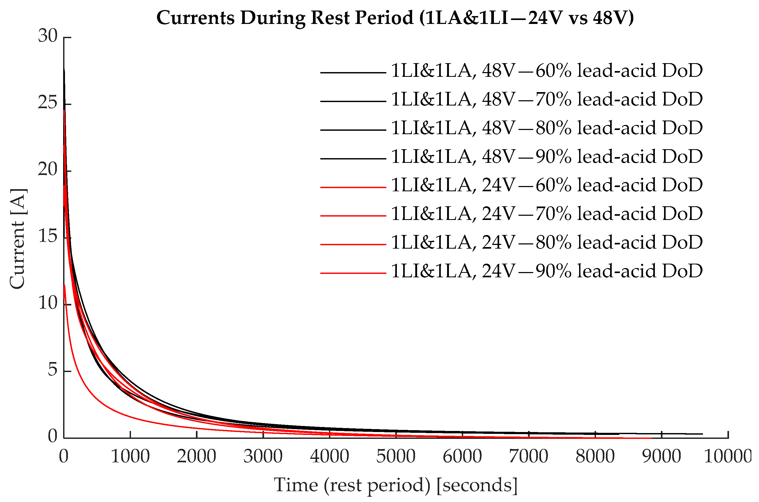
3.3. Hybrid Systems with Different Voltage Levels: 24 V vs. 48 V

Similar testing and analyses were carried out for the 48 V, 1LA&1LI hybrid system to understand how the hybrid behaviour changes when the system voltage is increased. For the 1LI&1LA 48 V system, parameters like the energy round-trip efficiency, coulombic efficiency, and total charge available remain the same as for the 24 V system. The total energy available, the Li-ion energy, discharged in the A–X region doubles as this varies linearly with the system voltage.
Figure 20 shows the lead-acid energy transfer between the strings for the 1LI&1LA—48 V system in comparison with the 1Li&1LA—24 V. The data indicated is for the 1C rate and the rest period recorded is for when the discharge process was stopped at 0 to 50% lead-acid string DoD. The total energy transferred follows the same shape as for the 24 V system, but the peak energy value doubles. The charge transferred between the strings is identical in both systems, as well as the peak transient currents during rest periods, as indicated in Figure 21.

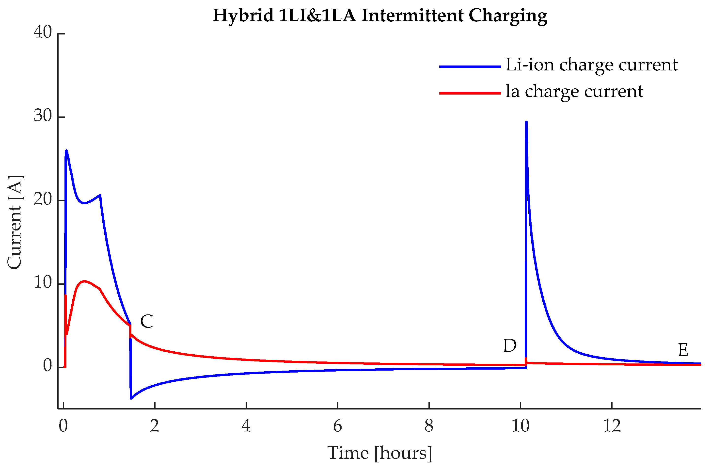
3.4. Intermittent Charging

Figure 2 (bottom) presents typical continuous charging waveforms of the investigated hybrid system. Figure 22 shows typical current waveforms during the intermittent charging of the 1LA&1LI system. If the charging process is stopped before the storage system reaches 100% SoC for both strings, energy is transferred from the Li-ions strings to the lead-acid battery. This is the opposite of what happens during discharge in the rest period. As explained above for the discharge scenario, this happens because of the different dynamic behaviour of both chemistries, which is linked to the diffusion and electrochemical processes within the cells.
Generally, it is undesirable to have energy and charge transfer between the strings as this impacts the round-trip efficiency of the system, as well as other possible degradation effects.
To illustrate the intermittent charging effects, in point C in Figure 22, the CC/CV charging process is stopped, and the system is left to rest for 8.2 h between points C and D. During this time, the Li-ion strings charge the lead-acid cells with the final top-up charge required to reach 100% SoC. At point D, the lead-acid cells reached full charge and the battery charger turned on to add the final charge to the Li-ion cells between points D and E. Depending on the total charging current being interrupted at point C, the whole charging process can take up to 1.5–2 times the normal time for continuous CC/CV charging. The transfer between C and D is massively reduced if the charger continues to inject even a small current into the system. This is important because in practical applications, like solar energy systems, it is unlikely that the charging or discharging current would be cut off abruptly, which implies that there would be little to no energy transfer between the strings.
The energy transferred between the strings has three main effects. The first is the slight efficiency loss because energy is moved from one string to the other. Depending on the current between the C and D points in Figure 22, the eventual efficiency loss is a function of the Li-ion string’s round-trip efficiency.
The second phenomenon is linked to ohmic losses. Because the internal resistance of lead-acid batteries is higher than Li-ion batteries, depending on the charging current, it can be beneficial to charge or discharge the Li-ion strings at a higher rate and, in the rest periods, to slowly transfer the energy to the lead-acid strings, thus minimizing thermal losses.
The third effect is linked with the overall battery storage system efficiency, which includes the inverter/charger operating efficiency. Figure 23 shows a typical efficiency curve for a battery storage inverter/charger as a function of its loading factor; the data are based on the SMA—Sunny Boy Storage inverter/charger. To fully charge a lead-acid cell takes anywhere between 10 and 15 h; bringing the lead-acid cells to a 100% SoC implies that a typical CC/CV charger will work for hours at the low-efficiency operating point, below a 5–10% loading factor. If the CC/CV process is stopped as it enters the CV mode, or when the current falls below a certain threshold, the Li-ion cells will take over the role of the CV charger and continue the process. In this way, we avoid drawing power from the grid at an efficiency below 90%.
To analyse the above effects, the 1LI&1LA, 1LI&2LA, 1LI&3LA, and 2LI&1LA systems were charged intermittently by cutting off the CV charging phase when the current reached the 0.5–0.1 C rate. Each time, the hybrid systems were left to rest until the circulation currents became negligible, at point D in Figure 21. The charging process was restarted immediately afterwards during the D–E interval. The maximum charge and energy transferred between the strings is very difficult to calculate as it depends on a multitude of factors like the CC charging current, the number of strings of the hybrid system, the CV current at the time of interruption, the rest time, and less obvious factors like the hysteresis of the system. The purpose of this analysis was to find the indicative charge transfers as a function of the current interruption because, from a practical perspective, this is the most important factor in approximating the overall operation efficiency. Figure 24 shows typical values for the charge transfers as a function of the interruption current value. The maximum values recorded did not rise above 15 Ah. The peak transfer occurred when the CV process was stopped between the 0.3 and 0.5C rate.
A model was built to calculate the overall hybrid system’s efficiency using the inverter/charger data in Figure 23. For illustration, typical results for the 1LI&2LA system are presented in Figure 24 and Figure 25. In this example, charge/discharge is performed at the 0.6C rate and the charging current interruption is performed at points 0.1–0.5C. The stand-alone battery energy round-trip efficiency thus measured varies very little with the charging current interruption. However, when the inverter/charger efficiency is considered, the overall efficiency drops below the initial values. As can be seen, if the system is charged continuously, the overall round-trip efficiency drop will be around 4.5% below the stand-alone values. Initially, the system efficiency rises when the system is intermittently charged, with the interruption currents between 0.05–0.1C. After the initial efficiency increase, the overall efficiency drops by 6–7% by the time it reaches the 0.5C current interruption.

4. Conclusions

This paper analyses the performance of five hybrid battery energy storage systems using Li-ion and lead-acid batteries that are connected directly in parallel, to understand their behaviour and quantify their performance. This was achieved by comparing various charging and discharging parameters across different hybrid systems with different numbers of strings and voltage levels.
The overarching conclusion is that directly coupled Li-ion (NMC) and lead-acid (VRLA) battery storage systems are possible since the arrangement is stable and the voltage profiles of the two chemistries allow for semi-active string control without power converters. This implies that part of the Li-ion energy capacity can be cycled independently of the lead-acid battery, thus offering the advantage of limiting the additional cost of power electronics that is generally associated with hybrid systems.
The first major conclusion of this study is that both the total energy available from a hybrid system and the energy available independently for frequent cycling are mainly driven by the number of lead-acid strings and the charge/discharge C rates. The number of strings modifies the total energy available by changing the equivalent electrical resistance and the dynamics of each type of battery. The Li-ion energy available for independent cycling can reach around 75–80% of the total Li-ion capacity that is available when batteries are coupled in hybrid configurations, but this happens for C rates below 0.2C. On average, across the 0.2–1C rates, each extra lead-acid string reduces the independent Li-ion capacity by around 8%. The total Li-ion energy available does not change, on average, with the number of strings, if the system is discharged below 10% DoD for the lead-acid battery; the Li-ion available energy is practically the same across all the different configurations analysed. However, the total energy available from the hybrid system depends on the lead-acid capacity; more strings imply less current per string for the same discharge current, and this means that more energy is available for cycling.
The second set of conclusions is related to the round-trip efficiency of the entire system. Again, the number of lead-acid strings relative to the Li-ion strings plays a crucial role. If we increase the number of Li-ion strings, the round-trip efficiency of the hybrid system when only the Li-ion is cycled is close to the stand-alone Li-ion efficiency values of 90–91% for the analysed cells. However, as the number of lead-acid strings is increased, the round-trip efficiency of the system drops by 10–11% per lead-acid string added. The measured round-trip efficiency value for the 1LI&3LA system when only the Li-ion is cycled drops to 68%. This happens because the lead-acid activity increases in the A–X region (Figure 5) with each added string. If the system is discharged less than 10% DoD for the lead-acid string, the system comes close to an overall 86–87%, which is relatively the same across the analysed system.
The third observation is that the charge and energy transfers between the strings are mainly driven by the number of Li-ion strings. The measured peak energy transferred between the strings is less than 7% of the total Li-ion energy that is independently available and is less than 1–2.5% of the total energy available. Also, increasing the number of lead-acid strings or the voltage of the whole system does not modify the peak transient currents and the peak energy transferred between the strings.
Finally, the paper briefly discusses intermittent charging and its effects on the overall performance of the system. The analysis indicates that energy and charge can be transferred between the strings during charging. This changes the round-trip efficiency of the complete (inverter and battery cell) hybrid storage system. Further research is needed into the control system of a hybrid system of lead-acid and lithium batteries working in parallel to improve the energy efficiency of this system type.
Further studies are required to determine the best applications for these types of systems and the performance of the battery store when coupled with other energy sources and real electrical loads. Additionally, research is needed to investigate the influence of the electrode properties of lithium-ion batteries on the performance of hybrid systems, including ones such as those using the latest developments in the field of lithium-ion batteries that are based on carbon nanotubes, as discussed in the context of Ref. [44].
No capacity degradation was observed in the reported experiments. This finding will be the subject of future research.

Supplementary Materials

The following supporting information can be downloaded at: https://www.mdpi.com/article/10.3390/en17184726/s1, The supplementary material includes the complete data for each hybrid system analysed except for the 1La&1LI system, the data for which are presented in the results section above.

Author Contributions

Conceptualization, A.D., S.M.S. and A.J.C.; methodology, A.D., S.M.S. and A.J.C.; software, A.D.; validation, A.D.; formal analysis, A.D.; investigation, A.D.; resources, S.M.S. and A.J.C.; data curation, A.D.; writing—original draft preparation, A.D.; writing—review and editing, S.M.S.; visualization, A.D.; supervision, S.M.S. and A.J.C.; project administration, S.M.S. and A.J.C.; funding acquisition, S.M.S. and A.J.C. All authors have read and agreed to the published version of the manuscript.

Funding

This research was funded by the Engineering and Physical Sciences Research Council (EPSRC) through the Centre for Doctoral Training in Energy Storage and its Applications, grant EP/L016818/1, and GS Yuasa Ltd.

Data Availability Statement

Data can be requested directly from the authors.

Acknowledgments

The authors wish to thank Peter Stevenson for his advice and support.

Conflicts of Interest

The authors declare no conflicts of interest. The funders had no role in the design of the study; in the collection, analyses, or interpretation of data; in the writing of the manuscript; or in the decision to publish the results.

Nomenclature

AhAmpere hour
BESSBattery energy storage system
CSPConcentrating solar power
DoDDepth of discharge
GW, GWhGigawatt, gigawatt hour
kW, kWhKilowatt, kilowatt hour
LI, LA/laLi-ion, lead-acid
OCVOpen circuit voltage
PVPhotovoltaic
SoCState of charge

References

  1. IEA. World Energy Outlook—2023; IEA: Paris, France, 2023; p. 661. [Google Scholar]
  2. REN21. Key Messages for Decision Makers; REN21: Paris, France, 2021; p. 32. [Google Scholar]
  3. IRENA. Renewable Power Generation Costs 2020; International Renewable Energy Agency: Masdar City, United Arab Emirates, 2021. [Google Scholar]
  4. Department for Business, Energy and Industrial Strategy. Modelling 2050: Electricity System Analysis; Department for Business, Energy and Industrial Strategy: London, UK, 2020. [Google Scholar]
  5. Zerrahn, A.; Schill, W.-P.; Kemfert, C. On the economics of electrical storage for variable renewable energy sources. Eur. Econ. Rev. 2018, 108, 259–279. [Google Scholar] [CrossRef]
  6. Schill, W.-P.; Zerrahn, A. Long-run power storage requirements for high shares of renewables: Results and sensitivities. Renew. Sustain. Energy Rev. 2018, 83, 156–171. [Google Scholar] [CrossRef]
  7. Woodward, E.; Still, C. Long Duration Electricity Storage in GB; Aurora: Oxford, UK, 2022; p. 43. [Google Scholar]
  8. Ramírez Torrealba, P.J. The Benefits of Pumped Storage Hydro to the UK; Technical Report; DNV KEMA Ltd.: London, UK, 2016; 50p. [Google Scholar]
  9. Media, S. UK Battery Storage Project Database Report. 2020. Available online: https://marketresearch.solarmedia.co.uk/products/uk-battery-storage-project-database-report (accessed on 17 September 2024).
  10. Hemmati, R.; Saboori, H. Emergence of hybrid energy storage systems in renewable energy and transport applications–A review. Renew. Sustain. Energy Rev. 2016, 65, 11–23. [Google Scholar] [CrossRef]
  11. Chong, L.W.; Wong, Y.W.; Rajkumar, R.K.; Rajkumar, R.K.; Isa, D. Hybrid energy storage systems and control strategies for stand-alone renewable energy power systems. Renew. Sustain. Energy Rev. 2016, 66, 174–189. [Google Scholar] [CrossRef]
  12. Hajiaghasi, S.; Salemnia, A.; Hamzeh, M. Hybrid energy storage system for microgrids applications: A review. J. Energy Storage 2019, 21, 543–570. [Google Scholar] [CrossRef]
  13. Zimmermann, T.; Keil, P.; Hofmann, M.; Horsche, M.F.; Pichlmaier, S.; Jossen, A. Review of system topologies for hybrid electrical energy storage systems. J. Energy Storage 2016, 8, 78–90. [Google Scholar] [CrossRef]
  14. Farhadi, M.; Mohammed, O. Energy storage technologies for high-power applications. IEEE Trans. Ind. Appl. 2015, 52, 1953–1961. [Google Scholar] [CrossRef]
  15. Lain, M.J.; Brandon, J.; Kendrick, E. Design Strategies for High Power vs. High Energy Lithium Ion Cells. Batteries 2019, 5, 64. [Google Scholar] [CrossRef]
  16. Kim, B.K.; Sy, S.; Yu, A.; Zhang, J. Electrochemical supercapacitors for energy storage and conversion. In Handbook of Clean Energy Systems; John Whiley and Sons: Hoboken, NJ, USA, 2015; pp. 1–25. [Google Scholar]
  17. IEA-ETSAP, I. Thermal Energy Storage: Technology Brief; International Renewable Energy Agency (IRENA): Masdar City, United Arab Emirates, 2013; p. 24. [Google Scholar]
  18. Dambone Sessa, S.; Tortella, A.; Andriollo, M.; Benato, R. Li-Ion Battery-Flywheel Hybrid Storage System: Countering Battery Aging During a Grid Frequency Regulation Service. Appl. Sci. 2018, 8, 2330. [Google Scholar] [CrossRef]
  19. Becker, J.; Nemeth, T.; Wegmann, R.; Sauer, D. Dimensioning and optimization of hybrid li-ion battery systems for EVs. World Electr. Veh. J. 2018, 9, 19. [Google Scholar] [CrossRef]
  20. Oxford, E.S. Powering Oxford to a Net Zero Future. 2021. Available online: https://energysuperhuboxford.org/ (accessed on 17 September 2024).
  21. PressCenter. Bosch: Double Battery for Energy Storage Facility in Braderup. 2014. Available online: https://presscenter.com/bosch-double-battery-for-energy-storage-facility-in-braderup/ (accessed on 17 September 2024).
  22. Held, L.; Gerhardt, N.; Zimmerlin, M.; Suriyah, M.R.; Leibfried, T.; Armbruster, M. Grid-friendly operation of a hybrid battery storage system. In Proceedings of the 25th International Conference on Electricity Distribution, Madrid, Spain, 3–6 June 2019. [Google Scholar]
  23. Thien, T.; Axelsen, H.; Merten, M.; Zurmühlen, S.; Münderlein, J.; Leuthold, M.; Sauer, D.U. Planning of grid-scale battery energy storage systems: Lessons learned from a 5 MW hybrid battery storage project in Germany. In Proceedings of the Battcon-International Stationary Battery Conference, Orlando, FL, USA, 12–14 May 2015; Hilton Bonnet Creek Orlando: Orlando, FL, USA, 2015; pp. 11–18. [Google Scholar]
  24. Thien, T.; Axelsen, H.; Merten, M.; Sauer, D.U. Energy management of stationary hybrid battery energy storage systems using the example of a real-world 5 MW hybrid battery storage project in Germany. J. Energy Storage 2022, 51, 104257. [Google Scholar] [CrossRef]
  25. Hayashi, K.; Mikami, Y.; Hirano, K.; Terayama, H. Development of Large-Scale Hybrid Power Storage System. 2020. Available online: https://www.hitachi.com/rev/archive/2020/r2020_04/04c02/index.html (accessed on 17 September 2024).
  26. Hitachi, L. Poland’s Largest Hybrid Battery Energy Storage System Commences Full-Scale Technology Demonstration. 2020. Available online: https://www.hitachi.eu/en/poland-largest-hybrid-battery-energy-storage-system (accessed on 17 September 2024).
  27. HOPPECKE. On the Grid: Innovative HOPPECKE Hybrid Storage System Successfully Commissioned. 2017. Available online: https://www.hoppecke.com/de/stories/show/am-netz-innovativer-hoppecke-hybrid-grossspeicher-erfolgreich-in-betrieb-genommen/ (accessed on 17 September 2024).
  28. Takeda, K.; Takahashi, C.; Arita, H.; Kusumi, N.; Amano, M.; Emori, A. Design of hybrid energy storage system using dual batteries for renewable applications. In Proceedings of the 2014 IEEE PES General Meeting|Conference & Exposition, Harbor, MD, USA, 27–31 July 2014; pp. 1–5. [Google Scholar]
  29. GS-Yuasa. GS Yuasa Power the World’s First Container Dual Chemistry Energy Storage System. 2019. Available online: https://www.yuasa.co.uk/2019/01/gs-yuasa-power-the-worlds-first-container-dual-chemistry-energy-storage-system/ (accessed on 17 September 2024).
  30. Yuasa, G. GS Yuasa Hybrid Battery for EV Charging Station—Portsmouth Port. 2021. Available online: https://www.yuasa.co.uk/2020/10/gs-yuasa-batteries-installed-in-ground-breaking-portsmouth-port-electric-vehicle-charging-station/ (accessed on 17 September 2024).
  31. BOS. BOS-LE300. 2021. Available online: https://www.bos-ag.com/products/le300/ (accessed on 17 September 2024).
  32. Elkadragy, M.M. Off-Grid Hybrid Systems Techno-Economic Study. 2020. Available online: https://uwaterloo.ca/waterloo-institute-sustainable-energy/grid-hybrid-systems-techno-economic-study (accessed on 17 September 2024).
  33. Elkadragy, M.M.; Alici, M.; Alsersy, A.; Opal, A.; Nathwani, J.; Knebel, J.; Hiller, M. Off-grid and decentralized hybrid renewable electricity systems data analysis platform (OSDAP): A building block of a comprehensive techno-economic approach based on contrastive case studies in Sub-Saharan Africa and Canada. J. Energy Storage 2021, 34, 101965. [Google Scholar] [CrossRef]
  34. Elkadragy, M.M.; Baumann, M.; Moore, N.; Weil, M.; Lemmertz, N.; Hiller, M. Contrastive Techno-Economic Analysis Concept for Off-Grid Hybrid Renewable Electricity Systems Based on comparative case studies within Canada and Uganda. In Proceedings of the 3rd International Hybrid Power Systems Workshop, Tenerife, Spain, 8–9 May 2018. [Google Scholar]
  35. Khazali, A.; Al-Wreikat, Y.; Fraser, E.J.; Sharkh, S.M.; Cruden, A.J.; Naderi, M.; Smith, M.J.; Palmer, D.; Gladwin, D.T.; Foster, M.P. Planning a hybrid battery energy storage system for supplying electric vehicle charging station microgrids. Energies 2024, 17, 3631. [Google Scholar] [CrossRef]
  36. Chung, S. Hybrid Lead-Acid/Lithium-Ion Energy Storage System with Power-Mix Control for Light Electric Vehicles. In Electrical and Computer Engineering; University of Toronto: Toronto, ON, Canada, 2016; p. 95. [Google Scholar]
  37. New Energy and Industrial Technology Development Organization (NEDO); et al. Demonstration Project in Germany Large-Scale Hybrid Power Storage System Starting to Operate in November. 2018. Available online: https://www.nedo.go.jp/english/news/AA5en_100396.html (accessed on 17 September 2024).
  38. International Renewable Energy Agency IRENA. Renewables: Costs and Market to 2030; International Renewable Energy Agency IRENA: Masdar City, United Arab Emirates, 2017. [Google Scholar]
  39. Chung, S.; Trescases, O. Hybrid energy storage system with active power-mix control in a dual-chemistry battery pack for light electric vehicles. IEEE Trans. Transp. Electrif. 2017, 3, 600–617. [Google Scholar] [CrossRef]
  40. Dascalu, A.; Fraser, E.J.; Al-Wreikat, Y.; Sharkh, S.M.; Wills, R.G.; Cruden, A.J. A techno-economic analysis of a hybrid energy storage system for EV off-grid charging. In Proceedings of the 2023 International Conference on Clean Electrical Power (ICCEP), Terrasini, Italy, 27–29 June 2023. [Google Scholar]
  41. Byrne, V.M.; Ng, P.K. Behaviour of systems mixing parallel strings of lithium-ion and lead-acid batteries for telecommunications applications. In Proceedings of the INTELEC 05-Twenty-Seventh International Telecommunications Conference, Berlin, Germany, 18–22 September 2005; IEEE: Piscataway, NJ, USA, 2005. [Google Scholar]
  42. Ng, P.K. Feasibility Study of Mixing Parallel Strings of Lithium-Ion Batteries and Lead Acid Batteries for Telecomunications Applications. In Proceedings of the 9th International Stationary Battery Conference, Orlando, FL, USA, 2–5 May 2005. Tyco/Electronics Power Systems. [Google Scholar]
  43. Feng, J.; He, Y.; Wang, G. Comparison study of equivalent circuit model of Li-Ion battery for electrical vehicles. Res. J. Appl. Sci. Eng. Technol. 2013, 6, 3756–3759. [Google Scholar]
  44. Shchegolkov, A.V.; Komarov, F.F.; Lipkin, M.S.; Milchanin, O.V.; Parfimovich, I.D.; Shchegolkov, A.V.; Semenkova, A.V.; Velichko, A.V.; Chebotov, K.D. Synthesis and study of carbon nanotube-based cathode materials for lithium-ion batteries. Neorg. Mater. Dec. Res. 2021, 12, 1281–1287. [Google Scholar]
Figure 1. Cell open circuit voltage characteristics of the batteries used in the experiments.
Energies 17 04726 g001
Figure 2. Laboratory battery-testing arrangement (left), data logger and sensors (middle), and the cells and batteries used in the experiment (right).
Energies 17 04726 g002
Figure 3. Experimental testing schematic.
Energies 17 04726 g003
Figure 4. Open-circuit voltage of the Li-ion and lead-acid batteries constituting the 24 V hybrid battery.
Energies 17 04726 g004
Figure 5. Typical 24 V hybrid Li-ion battery and lead-acid battery discharge (top) and charge (bottom) waveforms.
Energies 17 04726 g005
Figure 6. The energy [kWh] (top) and amp-hours [Ah] (bottom) discharged by the 24 V (1LI&1LA) system.
Energies 17 04726 g006
Figure 7. Li-ion battery energy and charge available during the discharge of the 1LA&1LI configuration between points A and X before the lead-acid string becomes fully active.
Energies 17 04726 g007
Figure 8. Lead-acid battery energy and charge discharged/charged during the A–X interval.
Energies 17 04726 g008
Figure 9. Round-trip energy efficiency of the individual strings (top) and total system energy round-trip efficiency (bottom).
Energies 17 04726 g009
Figure 10. Energy transfer between the strings during the D–E discharge rest period.
Energies 17 04726 g010
Figure 11. Li-ion and lead-acid discharged energy for the 1LI&2LA system.
Energies 17 04726 g011
Figure 12. Li-ion and lead-acid discharged energy for the 1LI&3LA system.
Energies 17 04726 g012
Figure 13. Li-ion and lead-acid discharged energy for the 2LI&1LA system.
Energies 17 04726 g013
Figure 14. Li-ion (top) and lead-acid (bottom) discharged energy, averaged across 0.2–1C rates, for different hybrid systems.
Energies 17 04726 g014
Figure 15. Li-ion discharged energy as a function of the discharged C rates (0.2–1C rates) for different hybrid system configurations.
Energies 17 04726 g015
Figure 16. Energy round-trip efficiency for different hybrid configurations vs. DoD.
Energies 17 04726 g016
Figure 17. Average discharged lead-acid energy during the A—B interval.
Energies 17 04726 g017
Figure 18. Average discharged lead-acid energy during the A—X interval.
Energies 17 04726 g018
Figure 19. Average energy transfer from the lead-acid to Li-ion batteries.
Energies 17 04726 g019
Figure 20. Energy transferred from the lead-acid battery to Li-ion strings in the 24 V and 48 V 1LA&1LI hybrid configurations.
Energies 17 04726 g020
Figure 21. Current during the rest period for both the 24 V and 48 V, 1LA&1LI hybrid configurations.
Energies 17 04726 g021
Figure 22. Current waveforms during the intermittent charging of the 1LI&1LA hybrid battery.
Energies 17 04726 g022
Figure 23. Inverter/charger efficiency.
Energies 17 04726 g023
Figure 24. Charge transferred from Li-ion to lead-acid during the C–D interval when the charging is interrupted vs. the equivalent C rate value of the current at the interruption point.
Energies 17 04726 g024
Figure 25. Intermittent charging round-trip efficiency.
Energies 17 04726 g025
Table 1. Battery data for the studied setup.
Battery/
Cell Type
Voltage Range [V]Capacity
[Ah]
Total
Energy [Wh]
Internal
Resistance [mΩ]
SWL330010.8–13.6 V
(Nominal 12 V)
100
(At C/10 rate)
1200
(At C/10 rate)
5.64
LEV502.75–4.1 V
(Nominal 4.1 V)
50
(At 1 C rate)
167.5 3.2
Table 2. Energy transfers between the strings due to the transient currents during the D–E rest period.
Hybrid/DoD%0%10%20%30%40%50%
1LI&1LA (0.2C)0.01830.01820.02440.03880.04270.0104
1LI&1LA (0.4C)0.02600.03360.04610.05800.06150.0128
1LI&1LA (0.6C)0.04800.04890.06890.07740.06210
1LI&1LA (0.8C)0.06170.06870.07420.06630.03450
1LI&1LA (1C)0.07210.08370.08840.05070.02170
Table 3. Energy round-trip efficiency comparison.
Hybrid/DoD%0%10%20%30%40%50%
1LA&1LI86.586.986.386.184.991.2
1LA&2LI87.886.586.386.786.589.3
2LA&1LI83.685.283.683.278.980.2
3LA&1LI68.877.981.883.184.185.0
Table 4. Average energy transferred between strings due to transient currents.
Hybrid/DoD%0%10%20%30%40%50%
1LI&1LA0.04520.05060.06040.05820.04450.0046
1LI&2LA0.02640.03350.04370.05360.06050.0015
1LI&3LA0.01930.02170.03080.04510.05920.0015
2LI&1LA0.07290.07930.10080.10710.09650.0051
Disclaimer/Publisher’s Note: The statements, opinions and data contained in all publications are solely those of the individual author(s) and contributor(s) and not of MDPI and/or the editor(s). MDPI and/or the editor(s) disclaim responsibility for any injury to people or property resulting from any ideas, methods, instructions or products referred to in the content.

