Abstract
The given power and grid frequency disturbances can cause transient oscillations and steady-state deviations in the output power of a virtual synchronous generator (VSG), which can be effectively addressed by adding transient damping. However, this approach may result in significant power overshoot. This article proposes an improved VSG control strategy based on transient electromagnetic power feedback compensation and a small-signal model reduction scheme. Firstly, the grid-connected active closed-loop small-signal models of typical VSG control and transient damping VSG control are established, respectively. The transient oscillation suppression mechanism of active power is revealed through root locus and frequency response analyses, and the power overshoot characteristics of the two control strategies are analysed by combining them with the system of zero points. Secondly, the active transient feedback compensation method and the small-signal model reduction design method are introduced in detail. Finally, comparative analysis experiments are conducted using the Matlab/Simulink and hardware-in-the-loop experimental platform. It is verified that the proposed control strategy can suppress transient oscillations in active power, prevent steady-state deviations, and effectively mitigate the power overshoot problem of the system.
1. Introduction
With the increasing penetration of renewable energy sources, power electronic devices’ low-inertia and weak-damping characteristics have profoundly impacted power grids’ dynamic performance and stability [1,2]. Energy storage systems, which are fast and flexible regarding power interaction and control mechanisms, effectively improve the inertia and damping characteristics of power electronic systems [3]. By emulating the swing equation and governor model of the synchronous generator (SG) [4], VSG technology provides voltage support and inertia simulation capabilities similar to SGs. This technology can effectively suppress power overshoot and oscillations during grid disturbances, thereby improving the frequency stability of grid-connected systems [5,6].
The incorporation of virtual inertia and damping coefficients transforms the VSG active power loop (APL) from a first-order system into a characteristic second-order oscillatory system, leading to transient oscillations and dynamic overshoot in the output power of the typical VSG (TVSG) in response to changes in the active command and grid frequency [7,8]. References [9,10] indicate that increasing the damping coefficient can suppress transient oscillations of active power and reduce dynamic overshoot. However, the damping characteristics of the TVSG are coupled with its primary frequency regulation (PFR) characteristics. Increasing the damping coefficient also intensifies the equivalent frequency regulation characteristics of the VSG, leading to a larger steady-state deviation when the grid frequency deviates from its nominal value [11,12]. Consequently, a conflict emerges between the transient and steady-state characteristics of TVSG upon grid connection. This suggests that effectively suppressing transient oscillations and concurrently rectifying the steady-state deviation induced by the fixed damping coefficients of the TVSG is a complex issue [13,14].
Scholars have undertaken extensive research to address the aforementioned conflict and enhance the system’s active response performance. This paper primarily investigates adaptive virtual inertia damping [15] and equivalent damping ratio methods [16]. Within the adaptive virtual inertia damping method, reference [17] introduces a Bang–Bang control strategy predicated on the intermittent alternation of virtual inertia. This strategy alternately sets the maximum and minimum values of virtual inertia based on the angular frequency deviation and its rate of change. However, the intermittent selection of virtual inertia can undermine the system’s stability. Reference [18] proposes a Bang–Bang control strategy grounded in continuous adaptive virtual inertia, which mitigates the transient oscillation issue induced by the intermittent setting of virtual inertia. References [19,20,21] investigate continuous adaptive control strategies based on the coordination of virtual inertia and damping coefficients from diverse control perspectives, thereby further enhancing the dynamic response characteristics of the TVSG during grid operation. However, these methods depend on fixed damping control strategies, with virtual inertia and damping coefficients remaining unchanged during steady-state conditions. This limitation fails to resolve the steady-state deviation in grid-connected active power due to the interaction between damping and PFR characteristics. Moreover, inadequate parameter adaptation can further undermine the stability of the TVSG during grid-connected operation [22].
The equivalent damping ratio method decouples the system’s dynamic and static characteristics by introducing transient damping. This approach effectively suppresses transient oscillations while addressing steady-state deviations caused by damping characteristics [23]. Reference [24] enhances transient damping by incorporating a first-order differential element into the VSG’s APL, thereby suppressing transient oscillations under active power disturbances. However, it fails to account for the high-frequency interference signals generated by the differential operation, thus limiting its practical applicability in engineering. Reference [25] introduces a VSG control strategy that utilizes band-pass damping power feedback, eliminating the need for a phase-locked loop and effectively mitigating high-frequency disturbances within the APL. Nonetheless, this implementation, which involves band-pass damping, elevates the TVSG from a second-order to a fourth-order oscillatory system, substantially augmenting the complexity associated with the design of the system’s control parameters. Reference [26] constructs transient damping by exploiting the high-frequency anti-interference characteristics of the lead-lag element, effectively suppressing high-frequency interference signals caused by the differential operation. However, the integration of the lead–lag compensator increases the control order of the APL system, which complicates the tuning of control parameters and obscures the methodology for establishing the dominant poles within the APL system’s dynamics. Reference [27] indicates that transient damping optimization control based on a first-order lead–lag element can result in significant overshoot in the active power output of the VSG during grid frequency variations. This overshoot may precipitate transient current surges and, in extreme cases, precipitate system instability. Additionally, fuzzy controllers [28] and neural network algorithms [29] are frequently employed to enhance the system’s active response performance. The VSG improvement strategy utilizing fuzzy controllers enables the adaptive adjustment of virtual inertia and damping coefficients, thereby enhancing both transient and steady-state performance. However, debugging fuzzy controllers is challenging, and system design complexity increases as the system becomes more intricate. VSG control based on neural networks can significantly improve control accuracy and system performance, but challenges such as long training times and high dependence on large datasets remain.
To address the issues above and enhance the active response performance of TVSG control, this paper proposes a VSG control strategy based on active transient feedback compensation. The proposed strategy in this paper aims to suppress system transient oscillations, mitigate steady-state deviations, and address the power overshoot issue of TVSG under disturbances. Firstly, grid-connected closed-loop small-signal models for TVSG control and transient damping VSG (TDP-VSG) are established. This paper then elucidates the conflict between suppressing transient oscillations and eliminating steady-state deviations in both control strategies. Furthermore, it examines the power overshoot issues in TVSG control under disturbances of active power commands and grid frequency. Secondly, a VSG control strategy for active transient feedback compensation (APFBC-VSG) is proposed. The transient oscillation suppression mechanism of the proposed strategy is analysed using root locus analysis, and the importance of suppressing power overshoot is demonstrated by examining the distribution trend of the system’s closed-loop zero points. Subsequently, a small-signal model step-down simplification method is proposed. The pre-reduction and post-reduction small-signal models are compared and analysed based on frequency domain response characteristics, with corresponding parameter design methods provided. Finally, comparative experiments are conducted using the Matlab/Simulink and the hardware-in-the-loop experimental platform to validate the feasibility and superiority of the proposed strategy.
2. Topology and Control Principles of TVSG
The main circuit topology and control architecture of the grid-connected TVSG are illustrated in Figure 1. Lf and Rf denote the filter inductance and the parasitic resistance of the inductance, respectively; iabc and uabc denote the three-phase voltage and current post-VSG filtering, respectively, while Lg is the line inductance.
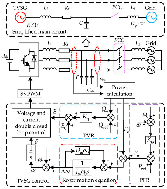
Figure 1.
TVSG topology and its control methods.
The TVSG emulates the operating characteristics of the SG to derive its rotor equation of motion, which can be expressed as follows:
where Jω is the virtual inertia parameter; Dω is the virtual damping coefficient; ω is the virtual angular frequency; ω0 is the rated angular frequency; Pm and Pe denote the virtual mechanical power and output active power of the TVSG, respectively.
The PFR and primary voltage regulation (PVR) equations for TVSG can be formulated as follows:
where Kω is the PFR coefficient; E0 is the no-load voltage of the VSG; Kq is the PVR coefficient; Qref is the reactive power adjustment command; and Qe is the instantaneous reactive power output of the TVSG.
This paper primarily focuses on optimizing the transient response performance of active power in TVSG. Given that TVSG’s grid-connected active and reactive power can achieve decoupled operation when the line impedance is predominantly inductive, the subsequent sections will exclude discussions on reactive power control and voltage–current dual-loop control [11].
3. Dynamic Response Characteristics of the TVSG
3.1. Transient Oscillation Mechanism of TVSG
The low-frequency characteristics of APL significantly impact the transient response performance of TVSG. Frequency domain analysis indicates that the voltage control loop has good followability in the low-frequency band, and the response speed of the voltage-current inner loop is significantly faster than that of the power outer loop. In this paper, the impact of the inner loop on the output characteristics of the APL in the VSG is not considered, as the focus is directed towards the system’s transient performance [23].
Based on the power transmission principle illustrated in Figure 1, the electromagnetic power output of the TVSG can be formulated as follows:
where Ug is the phase voltage of the grid; KT = 3EUg/X is the synchronization voltage coefficient; δ is the phase angle difference between the VSG and the grid voltage. Typically, δ is small, resulting in sinδ ≈ δ and cosδ ≈ 1; X is the equivalent impedance of the line. Combining Equations (1), (2) and (4), the control block diagram for TVSG grid-connected APL is illustrated in Figure 2.
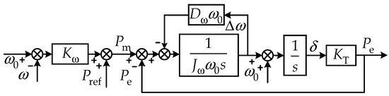
Figure 2.
Small-signal control block diagram of TVSG.
Based on Figure 2, the small-signal model of the closed-loop transfer function of the TVSG’s APL can be derived as follows:
In Equation (6),
where GPP(s) is the closed-loop transfer function of the output power for the given power disturbance; GPω(s) is the closed-loop transfer function of the output power for the grid frequency disturbance; ΔPe = Pe − Pref; Δωg = ωg − ω0; ΔPref is the given power disturbance step.
Equation (6) demonstrates that incorporating the virtual inertia Jω transforms GPP(s) into a typical second-order oscillatory system. In instances of active power disturbances or grid frequency dips, the grid-connected output active power of the TVSG undergoes transient oscillations and power overshoot issues. The damping ratio ξ and the natural oscillation angular frequency ωn of this second-order oscillatory system are defined by Equation (7).
The PFR coefficient Kω is determined by relevant standards. Consequently, Equation (7) indicates that the system damping ratio in the APL is related to Jω and Dω. Increasing Dω or decreasing Jω can enhance the damping ratio ξ, which effectively suppresses the transient oscillations in the TVSG output power. The main parameters of the TVSG are listed in Table 1.

Table 1.
VSG main circuit parameters.
Figure 3 illustrates the root locus of the closed-loop poles and zero points of the APL for the TVSG under various parameter selections. Analysis of the trend in the system’s closed-loop pole distribution reveals that the APL closed-loop system possesses a pair of conjugate poles. As the damping coefficient Dω varies in the same trend, the initial positions of the conjugate poles s1 and s2 approach the imaginary axis with an increase in Jω. This decreases the system’s damping ratio, weakening the stability and slowing the regulation rate of the TVSG. When Jω remains constant, an increase in Dω causes the conjugate poles s1 and s2 to gradually move towards two real-axis poles, as indicated by the arrows. This movement alters the system characteristics from underdamped to overdamped, which reduces the system’s response rate and steady-state control accuracy. These effects are consistent with the physical implications outlined in Equation (7).
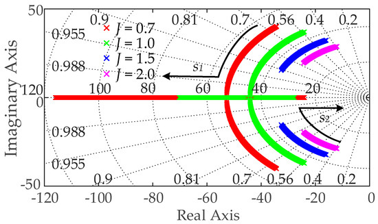
Figure 3.
The trend of pole distribution in APL small-signal model of TVSG.
3.2. Active Power Steady-State Deviation Issue
According to the self-synchronization characteristics of the TVSG during grid-connected operation [30], when the TVSG operates in a steady state, the frequency of its output voltage is determined by the grid frequency. If the grid frequency fluctuates, the grid-connected output frequency of the TVSG will deviate from the rated frequency, resulting in a frequency deviation. The active power output of the TVSG during steady-state operation is defined by Equation (8).
Equation (8) shows that when the grid frequency varies, the coupling of damping characteristics and PFR in the TVSG system can be represented as a droop control loop. The damping coefficient Dω can further exacerbate the steady-state deviation of the TVSG’s active power. The unit step response characteristics of the TVSG to given power disturbances and grid frequency disturbances are illustrated in Figure 4. The main circuit parameters are listed in Table 1.
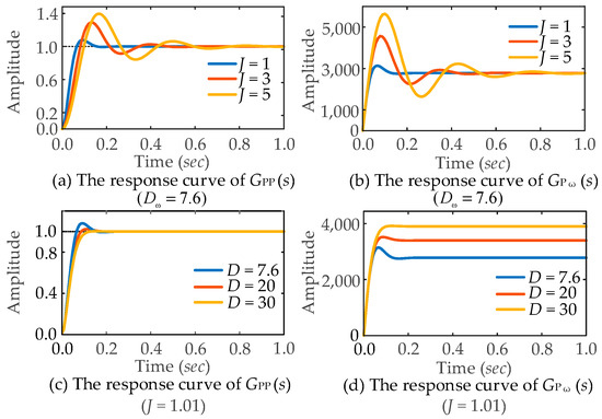
Figure 4.
Transient response characteristics of TVSG under different control parameters: (a) The response curve of GPP(s) (Dω = 7.6); (b) The response curve of GPω(s) (Dω = 7.6); (c) The response curve of GPP(s) (J = 1.01); (d) The response curve of GPω(s) (J = 1.01).
In practical engineering, to ensure that the power system has adequate inertia support, a larger virtual inertia coefficient Jω is usually selected. Figure 4a,b demonstrate that an increase in Jω intensifies the dynamic oscillation of the TVSG’s active power output. Hence, a larger damping coefficient Dω is required to meet the system’s need for power oscillation suppression. Figure 4c,d show that increasing Dω significantly enhances the TVSG control’s effectiveness in suppressing transient oscillations of the system’s active power, while gradually mitigating the power overshoot issue under grid frequency disturbances. However, increasing Dω also exacerbates the steady-state deviation of the TVSG’s active power. Therefore, the parameters Jω and Dω in TVSG control cannot be simultaneously optimized for both dynamic response and steady-state output power accuracy, necessitating a compromise in their determination.
4. Dynamic Response Characteristics of the TDP-VSG
To reconcile the dynamic and static characteristic requirements of VSG outputactive power, while mitigating dynamic power oscillations and eliminating the steady-state deviation induced by damping characteristics, an optimized transient damping control strategy based on a first-order lead–lag compensator for VSG has been developed. However, most of the existing literature focuses on analysing the performance of transient damping in suppressing transient oscillations and eliminating steady-state deviation [26]. It seldom analyses the difference between its transient response characteristics under given perturbation and grid frequency perturbation, nor does it analyse the overshoot problem caused by the implementation of transient damping. To tackle these issues, this chapter develops a frequency domain model of transient-damped VSG control based on a small-signal model. It analyses the transient oscillation mechanism and power overshoot issues in the transient damping VSG control system, focusing on the distribution trends of the closed-loop pole trajectories and zero points to understand the system’s dynamic behavior.
4.1. VSG Control with Transient Damping Characteristics
The control block diagram of the transient damping VSG employing a first-order lead–lag compensator is illustrated in Figure 5 [31]. It leverages the high-frequency anti-interference properties and low-frequency attenuation characteristics of the first-order lead–lag element within the damping control loop. This configuration ensures that the damping properties of the VSG are manifested exclusively during transient oscillations, without influencing the steady-state output of the VSG.
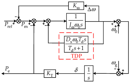
Figure 5.
Small-signal model control block diagram of TDP-VSG.
Utilizing the TDP-VSG control block diagram presented in Figure 5, the rotor motion equation for the TDP-VSG is derived as articulated in Equation (9) below:
where Td is the transient damping decay time constant, and Ds is the transient damping coefficient.
From Figure 5, the closed-loop small-signal model under given power disturbances and grid frequency disturbances is derived as follows:
where GPD(s) is the closed-loop small-signal model of the TDP-VSG’s grid-connected output power under a given power disturbance; GωD(s) is the closed-loop small-signal model of the TDP-VSG’s grid-connected output power under grid frequency disturbances; the coefficient a1 = Jωω0 + Td(Dsω0 + Kω), b1 = Kω + TdKT.
4.2. Transient Oscillation Mechanism of TDP-VSG Control
Equations (6) and (10) reveal that the introduction of transient damping adds a non-zero zero point and a pole to the APL of TVSG. The position of the zero point is related to the set decay time constant Td. To analyse the impact of TDP-VSG control parameters on the system’s stability performance, Figure 6 displays the zero-pole distribution diagrams under various Td, while the transient damping Ds is increased from 0 to 100.
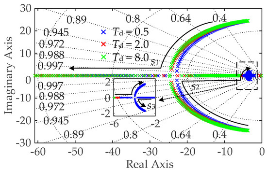
Figure 6.
The trend of pole distribution in APL small-signal model of TDP-VSG.
Comparing Equations (6) and (10), it becomes apparent that for small values of Td, Equation (10) closely approximates Equation (6), suggesting that the power compensation characteristic of transient damping is minimal. Additionally, as illustrated in Figure 6, when the transient damping Ds is constant, the system’s real pole progressively moves away from the imaginary axis as Td increases, resulting in an increased damping ratio and a decreased response rate. Therefore, to balance the stability and rapidity of the TDP-VSG system, the decay time constant is set to Td = 0.5.
From Figure 6, it is evident that at Td = 0.5, the introduction of transient damping Ds causes the real pole s3 move closer to the imaginary axis, while the conjugate poles s1 and s2 shift away from the imaginary axis, and the system continues to exhibit oscillatory characteristics. As Ds continues to increase, the conjugate poles s1 and s2 gradually transition into real poles, transforming the system from underdamped to overdamped, thereby eliminating oscillations. However, with further increases in Ds, the real poles s1 and s2 reform a conjugate pair, resulting in a reduced damping ratio and diminished stability of the TDP-VSG system, indicating that the selection margin for the transient damping coefficient Ds is quite limited.
4.3. Analysis of Active Power Overshoot Problem of TDP-VSG
To further investigate the power overshoot phenomenon in the TDP-VSG system, the zero point distributions of both the TVSG system and the TDP-VSG system are derived from Equations (6) and (10), respectively, as presented in Table 2.
Table 2.
Zero points comparison between TDP-VSG and TVSG.
As illustrated in Equation (6), the closed-loop transfer function of TVSG under active power disturbance contains no zero points. Under grid frequency disturbances, the closed-loop transfer function features a zero point −(Dsω0 + Kω)/(Jωω0) that is significantly distant from the imaginary axis, thereby exerting a minimal impact on system stability. Furthermore, as the damping coefficient Ds increases, the system’s zero points shift further from the imaginary axis. Consequently, for TVSG, increasing Ds mitigates transient oscillations and resolves the power overshoot issue induced by grid frequency disturbances, consistent with the step response characteristics of TVSG presented in Figure 4.
Rearranging the aforementioned equation yields the following:
The expression for the discriminant Δ is derived from the above equation as follows:
Based on the discriminant expression provided in Equation (13), where Δ > 0, the two zero points z1 and z2 of GωD(s) are real zero points. Their explicit expressions are as follows:
As illustrated in Table 2, the closed-loop transfer function of the TDP-VSG control under given power disturbances features a fixed zero point −1/Td. An increased Td shifts this zero point closer to the imaginary axis, leading to the TDP-VSG control’s ability to suppress transient oscillations. However, this also results in a significant overshoot in the response characteristics of GPD(s). The closed-loop transfer function GωD(s) of the TDP-VSG control under grid frequency disturbances contains zero points that vary with the transient damping coefficient Ds. Zero-point z2 is located further from the imaginary axis and continues to move further away as Ds increases, indicating that z2 exerts a weaker influence on the overshoot of the response characteristics. In contrast, zero z1 is nearer to the imaginary axis and, as Ds increases, z1 grows larger than −1/Td and progressively approaches the imaginary axis. This significantly affects the overshoot of the TDP-VSG output response characteristics.
To validate the theoretical analysis, the unit step response curves of the TDP-VSG control under given power disturbances and grid frequency disturbances, derived from the closed-loop transfer function in Equation (10), are illustrated in Figure 7. As illustrated in Figure 7a,b, with the incremental increase in transient damping, the oscillation suppression capability of the TDP-VSG system becomes increasingly pronounced. Nevertheless, power overshoot issues persist during disturbances, particularly in grid frequency disturbances. This observation aligns with the previous analysis, leading to the choice of Ds = 20 for this study. As evidenced by Figure 7c,d, transient damping exhibits a limited effect on suppressing the system’s dynamic oscillations when the decay time constant Td is very small. As Td increases, the system’s oscillation performance improves; however, the steady-state recovery time is extended. This observation is consistent with the prior analysis, leading to the choice of Td = 0.5 for this study.
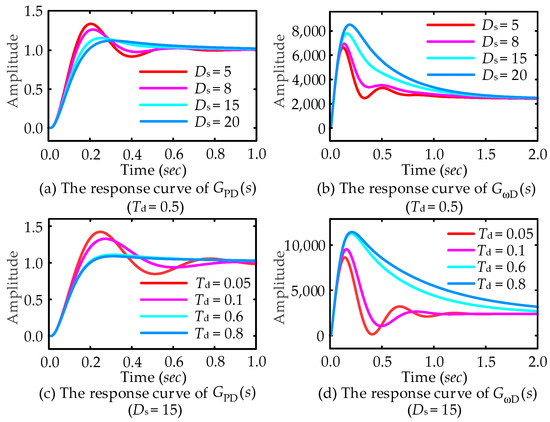
Figure 7.
Transient response characteristics of TDP-VSG under different control parameters: (a) The response curve of GPD(s) (Td = 0.5); (b) The response curve of GωD(s) (Td = 0.5); (c) The response curve of GPD(s) (Ds = 15); (d) The response curve of GωD(s) (Ds = 15).
In summary, integrating transient damping characteristics into the TDP-VSG control effectively mitigates the steady-state bias introduced by the damping features of the TVSG and attenuates transient oscillations. However, the selection range for the steady-state damping coefficient remains relatively narrow. Furthermore, a significant power overshoot exists, particularly during grid frequency disturbances.
5. Improved VSG Control Strategy Based on Active Transient Feedback Compensation
This chapter presents an enhanced VSG control strategy to tackle the substantial overshoot problem encountered by TDP-VSG under grid disturbances. This strategy is based on active power transient feedback compensation and is informed by transient damping control techniques. By developing its small-signal model for grid-connected active power, the chapter analyses the transient oscillation suppression mechanism of the active power transient feedback control and offers a comprehensive parameter design framework. This active power transient feedback control is referred to as APFBC-VSG throughout this paper for ease of subsequent analysis.
5.1. APFBC-VSG Control and Its Small-Signal Analysis
A compensation mechanism based on active power transient feedback is incorporated into the APL to mitigate transient oscillations in grid-connected power. Consequently, the enhanced APL of the VSG can be expressed by Equation (15).
where PAPFBC is the active power transient feedback compensation. Its precise formulation is provided in Equation (16).
where TFB is the decay time constant of the APFBC-VSG and KFB is the transient power compensation coefficient. This transient compensation power is active only during transient oscillations, thus having no impact on the steady-state output of the VSG. Based on Equations (15) and (16), the active closed-loop control block diagram for the APFBC-VSG control is depicted in Figure 8.
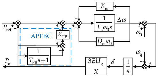
Figure 8.
Small-signal model control block diagram of APFBC-VSG.
Referring to Figure 8, the closed-loop small-signal model of the APFBC-VSG control under active power disturbances or grid frequency disturbances is formulated as presented in Equation (17).
where GPAPFBC(s) is the closed-loop small-signal model of the APFBC-VSG grid-connected output power under given power disturbances; GωAPFBC(s) is the closed-loop small-signal model of the VSG grid-connected output power under grid frequency disturbances, where a2 = Jωω0 + TFB(Dωω0 + Kω), b2 = Dωω0 + Kω + TFBKT(1 + KFB).
The steady-state deviation of the APFBC-VSG control during grid-connected operation, as derived from Equation (17), is expressed by the following equation:
In summary, setting Dω = 0 can eliminate the steady-state deviation induced by the interaction between Dω and Kω. Conversely, by comparing and analysing Equations (6) and (17), it is evident that similar to the TDP-VSG control, the APFBC-VSG control adds a zero point and a pole in its APL and changes the original distribution of zero points and poles, thereby modifying the original distribution of zero points and poles. With appropriate parameter configuration, this approach will effectively suppress transient oscillations in power and enhance system stability.
5.2. Transient Oscillation Mechanism of APFBC-VSG Control
Rearranging Equation (17) gives the following:
where c = Jωω0s2 + (Dωω0 + Kω)s + KT.
From Equation (19), it is evident that if TFBKTKFB is relatively small, Equation (19) approximates Equation (6), resulting in weaker feedback compensation and diminished effectiveness in suppressing transient oscillations in the VSG. Consequently, TFBKTKFB should not be excessively small. Furthermore, since KT is generally large, selecting a smaller TFBKFB can enhance the system’s transient stability performance.
Based on Equation (19), Figure 9 depicts the system pole distribution curves for APFBC-VSG control, varying with the decay time constant TFB and the compensation coefficient KFB. Figure 9a illustrates the pole distribution for TFB = 0.004 as KFB increases from 0 to 20. Compared to the pole distribution of TVSG control, APFBC-VSG control introduces a negative real pole sFB3 that is initially positioned far from the imaginary axis. As KFB increases, sFB3 gradually approaches the imaginary axis but remains relatively distant, thus exerting only a minor impact on system stability. With increasing KFB, the dominant poles sFB1 and sFB2 of APFBC-VSG control progressively move closer to the real axis, enhancing system stability. When KFB = 15.1, these poles transition into negative real poles, shifting the system from underdamped to overdamped. Consequently, APFBC-VSG enhances the system’s equivalent damping characteristics and effectively mitigates transient oscillations.
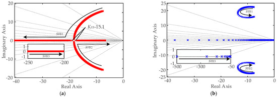
Figure 9.
The trend of pole distribution in APL small-signal model of APFBC-VSG: (a) TFB = 0.004, KFB increases from 0 to 20; (b) KFB = 2, TFB increases from 0 to 20.
Figure 9b illustrates the pole distribution at KFB = 0.8 and the decay time constant TFB increases from 0 to 2. Initially, the newly introduced dominant poles sFB1 and sFB2 in the APFBC-VSG control move away from the imaginary axis. However, as TFB increases, these poles gradually approach the imaginary axis. The displacement range of the conjugate poles is relatively small, resulting in a minor impact on the system’s damping ratio. This indicates that the choice of TFB has a limited effect on system stability. Additionally, although the conjugate poles sFB1 and sFB2 are close to the imaginary axis and primarily influence the system’s stability, the newly introduced real pole sFB3 in APFBC-VSG control approaches the imaginary axis as TFB increases. Despite this, sFB3 does not become a dominant pole and thus has a minimal effect on system stability. As TFB increases, the newly introduced real pole sFB3 in APFBC-VSG control approaches the imaginary axis.
5.3. The Characterisation of APFBC-VSG Power Overshoot Suppression
To facilitate a comprehensive analysis of the power overshoot suppression efficacy of the APFBC-VSG control strategy during grid disturbances, Table 3 presents the zero points distributions for TVSG, TDP-VSG, and APFBC-VSG under both given power disturbances and grid frequency disturbances. As derived from Equation (18), the APFBC-VSG control effectively eliminates the steady-state deviation associated with damping characteristics by setting Dω = 0. Consequently, this leads to a distinct zero distribution under grid frequency disturbances in comparison to the TVSG control, where zero point −(Dωω0 + Kω)/(Jωω0) is approximately equivalent to zero point −Kω/(Jωω0).
Table 3.
The zero points distribution under different VSG control strategies.
Based on the earlier theoretical analysis, the APFBC-VSG control exhibits a smaller TFB than the TDP-VSG control. Under given power disturbances, the zero point −1/TFB of GPAPFBC(s) is positioned significantly far from the imaginary axis, which effectively results in the absence of an overshoot in the active power response. For grid frequency disturbances, one zero point −1/TFB of GωAPFBC(s) is situated far from the imaginary axis, resulting in a minimal overshoot in the power response characteristics. Additionally, another zero point Kω of −Kω/(Jωω0) holds a larger value, causing −Kω/(Jωω0) to be smaller than −1/Td, which implies that zero point −Kω/(Jωω0) is situated further from the imaginary axis compared to zero point −1/Td. Therefore, the overshoot observed in the APFBC-VSG system response is considerably smaller than that in the TDP-VSG system.
To validate the theoretical analysis, Figure 10 presents the unit step response curves of the APFBC-VSG control under both given power disturbances and grid frequency disturbances, derived from the closed-loop transfer function in Equation (17). As illustrated in Figure 10a,b, increasing the power compensation coefficient enhances the active oscillation suppression performance of the APFBC-VSG system, significantly reducing the power overshoot under given power disturbances and grid frequency disturbances. These results align with the previous analysis; thus, the chosen value is KFB = 20. Figure 10c,d demonstrate that varying the decay time constant TFB has a negligible effect on system stability, supporting the earlier analysis. Consequently, TFB = 0.006 is selected.
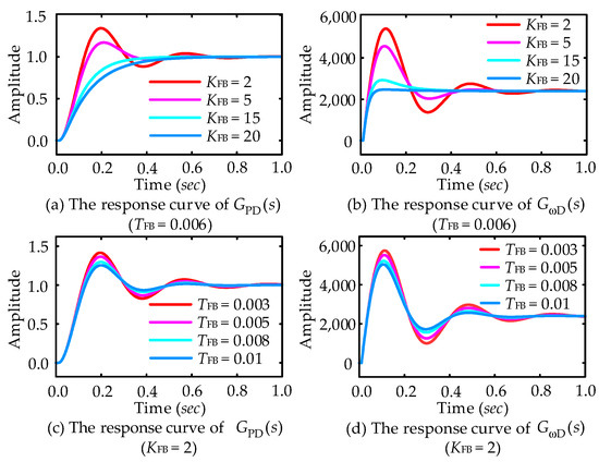
Figure 10.
Transient response characteristics of APFBC-VSG under different control parameters: (a) The response curve of GPD(s) (TFB = 0.006); (b) The response curve of GωD(s) (TFB = 0.006); (c) The response curve of GPD(s) (KFB = 2); (d) The response curve of GωD(s) (KFB = 2).
5.4. APFBC-VSG Small-Signal Model Downscaling and Parameter Design
A comparison of Equations (6) and (17) reveals that incorporating active power transient feedback compensation in the APFBC-VSG control enhances system stability. However, this modification also transforms the VSG control system from a second-order oscillatory system to a third-order system, making the determination of system control parameters more complex. Figure 9 illustrates that, with the compensation coefficient KFB held constant, variations in the decay time constant TFB have a negligible impact on the positioning of the dominant conjugate poles. KFB predominantly influences the system’s stability. Based on this analysis, this paper proposes a simplification approach for reducing the order of the small-signal model by excluding terms in the closed-loop transfer function GPAPFBC(s) that involve TFB but not KFB. The small-signal model step-down simplification method for the APFBC-VSG, denoted as GPFBC(s), is provided in Equation (20).
To validate the effectiveness of the small-signal model step-down simplification method proposed in this paper, Figure 11 presents the step response characteristic curves of the closed-loop small-signal model of the APFBC-VSG control before and after simplification, derived from Equations (17) and (20) respectively. Figure 11a shows the unit step response characteristics of GPAPFBC(s) and GPFBC(s) with TFB = 0.006 as the compensation coefficient KFB gradually increases. Figure 11b shows the unit step response characteristics of GPAPFBC(s) and GPFBC(s) with KFB = 2, as the decay time constant TFB gradually increases.
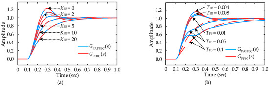
Figure 11.
Step response characteristics of the system before and after order reduction: (a) the response curve with a change in TFB; (b) the response curve with a change in KFB.
Figure 11a illustrates that as KFB increases, the step response characteristics of the reduced-order small-signal closed-loop transfer functions GPAPFBC(s) and GPFBC(s) remain nearly identical before and after the reduction. Figure 11b demonstrates that with a small TFB, the step response characteristics of the small-signal closed-loop transfer functions GPAPFBC(s) and GPFBC(s) before and after the step-down also almost coincide, confirming the efficacy of the proposed small-signal model reduction simplification method. However, with a large TFB, the zero points and poles in the APFBC-VSG control approach the imaginary axis, significantly impacting system stability and inducing oscillations in GPAPFBC(s) under active power disturbances. This observation is consistent with the earlier theoretical analysis, suggesting that TFB should be kept small.
Equation (20) shows that the simplified transfer function GPFBC(s) based on the small-signal model step-down method becomes a typical second-order oscillation system. The control parameters of the APFBC-VSG algorithm can be tuned and optimized according to the cut-off frequency requirements and phase angle constraints dictated by classical control theory for optimal system performance. From Equation (20), it can be deduced that the damping ratio and natural oscillation frequency corresponding to the APFBC-VSG system can be expressed by Equation (21).
Using Equation (21), the expressions for the phase margin and cutoff frequency corresponding to GPFBC(s) can be further derived as follows:
In accordance with classical control theory, to guarantee that the APFBC-VSG system exhibits robust stability and swift response during grid operation, ξFBC should exceed a threshold value to ensure stability, typically within the 0.707 < ξFBC < 1 range. Furthermore, the phase margin should be maintained within γFBC > 45°. Utilizing these parameter selection methodologies and substituting the derived characteristic parameter values into Equations (21) and (22), an optimal design for the compensation coefficient KFB and the decay time constant TFB can be realized.
6. Simulation Verification and Analysis
To validate the effectiveness of the proposed control strategy, a single-machine VSG grid-connected converter simulation model was developed using Matlab/Simulink, as illustrated in Figure 1. This simulation model compared the performance of TVSG control, TDP-VSG control, and the proposed APFBC-VSG control in suppressing power oscillations under given power and grid frequency disturbances. The main simulation parameters are listed in Table 1. The specific operating conditions are as follows: the system’s active power command increases from 0 kW to 15 kW at 2 s and the grid frequency increases from 50 Hz to 50.1 Hz at 4 s, and returns to 50 Hz at 6 s.
6.1. Analysis of Fixed Damping Characteristics in TVSG Control
To evaluate the influence of fixed damping characteristics on the system’s transient stability, simulation experiments with varying Dω coefficients in TVSG control were performed. The results are presented in Figure 12, which shows that the absence of damping characteristics in the TVSG control leads to a power overshoot of 7.6 kW and an oscillation duration of 1.7 s during given power disturbances. Additionally, a steady-state deviation occurs due to PFR characteristics during grid frequency variations. When Dω increases to 10, the power overshoot during given power disturbances reduces to 1.9 kW, and the oscillation time shortens to 0.6 s. However, the steady-state deviation under grid frequency disturbances rises to 3.5 kW. Consistent with the output characteristics of TVSG shown in Equation (6) and the corresponding theoretical analysis, as Dω increases, the power overshoot in TVSG control diminishes, and the adjustment time shortens, yet the steady-state deviation of the system output is further exacerbated. The simulation results and analysis confirm that increasing Dω in TVSG control effectively suppresses transient oscillations and reduces power overshoot. However, this adjustment also leads to an increase in the steady-state deviation of the output power.
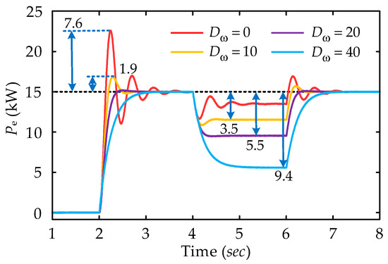
Figure 12.
Simulation results of fixed damping control under different Dω.
6.2. The Analysis of Transient Damping Characteristics of TDP-VSG Control
To analyse the effect of first-order hysteresis-based transient damping characteristics Ds on the transient stability performance of the system, simulation experiments are carried out for the TDP-VSG control with various transient damping coefficients. The simulation results are detailed in Figure 13.
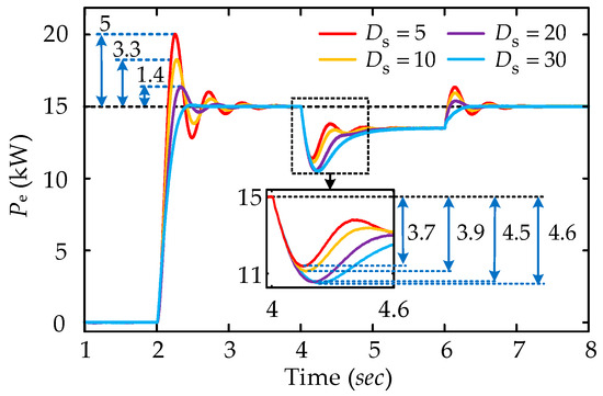
Figure 13.
Simulation results of TDP-VSG control under different transient damping coefficients.
When Ds = 5, the TDP-VSG control experiences a given power disturbance at 2 s, leading to significant transient oscillations with the power overshoot of 5 kW and the steady-state recovery time of 1.6 s. At 4 s, during the grid frequency disturbance, the TDP-VSG control effectively eliminates the steady-state deviation induced by the damping characteristics, with a peak overshoot power of 3.7 kW. A comparison of active power outputs under various transient damping characteristics indicates that the TDP-VSG’s capability to suppress transient oscillations progressively enhances as Ds increases. However, a significant overshoot issue still exists, especially in the case of grid frequency disturbance, as the overshoot of the system output power increases with the increase in Ds. The simulation results are consistent with the output characteristics and transient performance theoretical analysis of the TDP-VSG control as shown in Equation (10), demonstrating that while the introduction of transient damping effectively addresses transient oscillation suppression and steady-state deviation elimination, it leads to considerable power overshoot issues. This is particularly evident under grid frequency disturbances, where the system’s active power overshoot positively correlates with Ds.
6.3. The Analysis of Transient Damping Characteristics of APFBC-VSG Control
To validate the transient oscillation suppression capabilities of the proposed control strategy, simulation experiments were performed on the APFBC-VSG control with varying compensation coefficients KFB, as illustrated in Figure 14. The figure demonstrates that at KFB = 0, the APFBC-VSG control effectively resembles the TVSG control, exhibiting obvious transient oscillation and power overshoot during given power and grid frequency disturbances. With the implementation of transient feedback compensation and as KFB progressively increases, both transient oscillations and power overshoots in the APFBC-VSG output are substantially mitigated. When the coefficient KFB = 15, the system’s transient oscillations are eliminated, and the output power under both given power and grid frequency disturbances exhibits minimal disturbance overshoot. The simulation results are consistent with the output characteristics and transient performance theoretical analysis of the APFBC-VSG control as shown in Equation (17), validating the effectiveness of the APFBC-VSG control strategy, particularly in enhancing system stability performance.
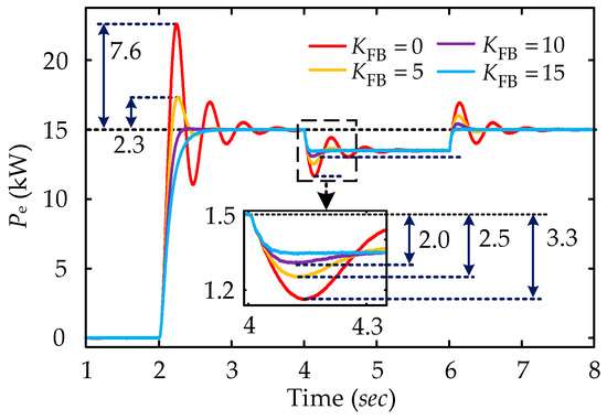
Figure 14.
Simulation results of APFBC-VSG control under different compensation coefficients.
6.4. The Analysis of Transient Oscillation Suppression Mechanism with Different VSG Control Strategies
To further illustrate the advantages of the APFBC-VSG control strategy, a comparative simulation was performed among TVSG control, TDP-VSG control, and APFBC-VSG control, each configured with optimal control parameters. Each control strategy’s dynamic and static characteristics were analysed under given power disturbances and grid frequency disturbances. The simulation parameters are as follows: for TVSG control, the steady-state damping coefficients Dω are set at 0 and 20; for TDP-VSG control, the transient damping coefficient Ds is 30 with the decay time constant Td = 0.5; for APFBC-VSG control, the transient compensation coefficient is KFB = 20 with the decay time constant TFB = 0.006. The simulation results are detailed in Figure 15, and the values of VSG response overshoot for each control strategy are summarized in Table 4.
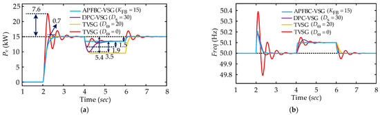
Figure 15.
Simulation results under different VSG control strategies: (a) active power output characteristic simulation curve; (b) frequency output characteristic simulation curve.
Table 4.
The overshoot characteristics of VSG systems under different VSG control strategies.
Based on the data presented in Figure 15 and Table 4, it is evident that when Dω = 0, the TVSG control exhibits substantial oscillations under both given power disturbances and grid frequency disturbances, with the power overshoot of 7.6 kW and 3.5 kW, respectively, and a prolonged transient oscillation duration. When Dω = 20, the damping in TVSG control effectively suppresses transient oscillations but leads to considerable steady-state power deviation. The TDP-VSG control, incorporating transient damping, significantly enhances system transient stability and alleviates steady-state power deviation issues. Nonetheless, it continues to exhibit substantial power overshoot problems, with the power overshoot of 0.7 kW and 3.5 kW under given power disturbances and grid frequency disturbances, respectively. In contrast, the proposed APFBC-VSG control strategy effectively mitigates system transient oscillations and power overshoot under both given power and grid frequency disturbances, significantly reduces system regulation time, and provides superior frequency response performance. Compared to alternative control strategies, it achieves faster response rates, reduced frequency deviations, and offers exceptional frequency support capabilities, fully utilizing VSG control’s damping and inertia characteristics in high renewable energy penetration scenarios.
Figure 16 illustrates the simulation results comparing currents under various VSG control strategies.
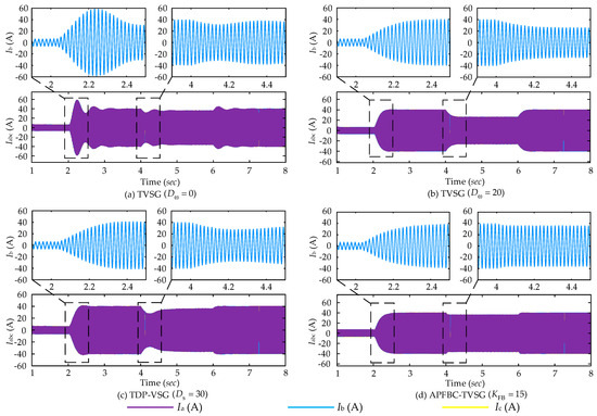
Figure 16.
Simulation results of grid-connected output current under different VSG control strategies: (a) The simulation output three phase current of TVSG (Dω = 0); (b) The simulation output three phase current of TVSG (Dω = 20); (c) The simulation output three phase current of TDP-VSG (Ds = 30); (d) The simulation output three phase current of APFBC-VSG (KFB = 15).
When Dω = 0, TVSG control demonstrates substantial oscillations in the output current, accompanied by large transient currents that may trigger overcurrent protection, potentially causing system instability. When Dω = 20, including steady-state damping, TVSG control effectively mitigates output current oscillations under grid disturbances. However, it results in an obvious steady-state deviation in active power during grid frequency disturbances, which significantly impacts the stability of the grid-connected system. The TDP-VSG control, incorporating transient damping, exhibits robust transient stability under grid disturbances. Nevertheless, power overshoot issues lead to pronounced current oscillations during grid frequency disturbances. In contrast, the proposed APFBC-VSG control exhibits minimal transient oscillations and avoids significant overshoot in the output grid current during given power disturbances and grid frequency disturbances. The system promptly returns to a steady state following disturbances, demonstrating that the proposed APFBC-VSG control effectively mitigates current oscillations and overshoot, thus offering stable power support for large-scale renewable energy integration.
7. Experimental Verification
To further validate the effectiveness of the proposed control strategy, experimental verification was carried out on a hardware-in-the-loop (HIL) system development platform, as depicted in Figure 17. The experimental procedure involved splitting the real-time model of the system. The system’s main circuit topology was uploaded to the HIL real-time simulator’s field-programmable gate array (FPGA), while the control program was loaded onto the central processing unit (CPU). A mapping relationship between the main circuit and the control program was established through the host computer interface. This configuration enabled the execution of the hardware-in-the-loop (HIL) semi-physical experiment. The control parameters used in the hardware experiments were aligned with those employed in the simulations. Test Condition 1 involved stepping the active power command Pref from 0 kW to 15 kW, whereas Test Condition 2 maintained Pref at 15 kW while increasing the grid frequency from 50 Hz to 50.1 Hz. The detailed experimental results are illustrated in Figure 18.
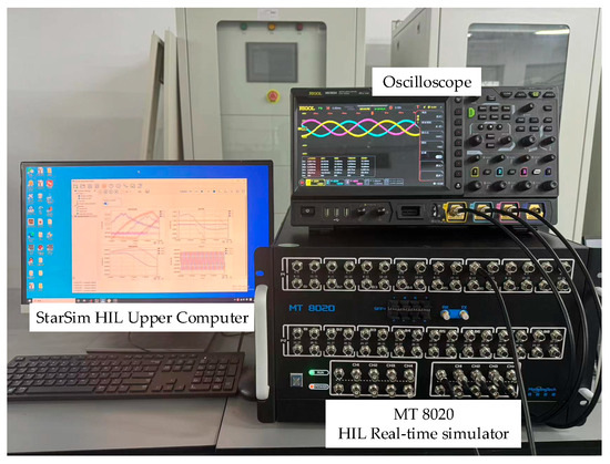
Figure 17.
HIL hardware experiment platform.
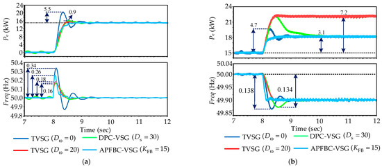
Figure 18.
Experimental results: (a) comparative experimental results of different control strategies under given power disturbance; (b) Comparative experimental results of different control strategies under grid frequency drop.
As shown in Figure 18a, when Dω = 0, the TVSG exhibits significant transient oscillations under active power disturbances, with a power overshoot of 5.5 kW and a frequency deviation of 0.34 Hz. When Dω = 20, the transient oscillations and power overshoot are effectively mitigated, reducing the system’s frequency deviation to 0.18 Hz. The inclusion of transient damping in the TDP-VSG control successfully suppresses transient oscillations during active power disturbances, resulting in a smaller power overshoot and a frequency deviation of 0.16 Hz. Notably, the proposed APFBC-VSG control almost completely eliminates transient oscillations and power overshoot during active power disturbances, achieving a frequency deviation of 0.26 Hz and enabling a smooth transition in VSG output power.
As shown in Figure 18b, when Dω = 0, the TVSG experiences significant transient oscillations when the grid frequency drops by 0.1 Hz, with a power overshoot of 4.7 kW and a frequency deviation of 0.138 Hz. When Dω = 20, the transient oscillations and power overshoot are effectively mitigated, but a substantial steady-state power deviation of 7.2 kW remains. The TDP-VSG control, incorporating transient damping, successfully suppresses transient oscillations during grid frequency drops, although it still exhibits a power overshoot of 7.2 kW, with a frequency deviation of 0.134 Hz. The proposed APFBC-VSG control effectively suppresses both transient oscillations and power overshoot during grid frequency drops and demonstrates a faster regulation rate compared to other control strategies.
In summary, TVSG control with fixed damping efficiently mitigates transient oscillations under both given power disturbances and grid frequency disturbances, but it results in substantial steady-state active power deviations. The TDP-VSG control, utilizing transient damping, resolves the steady-state deviations caused by damping characteristics under grid frequency disturbances. However, it experiences severe power overshoot issues, which may result in transient currents exceeding limits and activating overcurrent protection. In contrast, the proposed APFBC-VSG control strategy demonstrates superior performance in suppressing transient oscillations and enhancing transient response compared to other control strategies. It maintains stable output power without overshoot under both given power and grid frequency disturbances, thereby offering robust support for integrating renewable energy sources into the grid.
8. Conclusions
To tackle the challenges of transient oscillations, steady-state deviations, and power overshoot inherent in traditional VSG control strategies under given power and grid frequency disturbances, this paper proposes a VSG control strategy utilizing active power transient feedback compensation. This strategy integrates small-signal modeling with root locus distribution trends to provide a comprehensive theoretical analysis. The conclusions drawn from both simulations and HIL experiments are as follows:
- (1)
- The TVSG based on fixed damping control cannot simultaneously satisfy the system’s needs for transient oscillation suppression and steady-state deviation correction. Based on the transient characteristics simulation analysis of TVSG control, it is observed that as the fixed damping coefficient increases, the transient oscillation suppression performance of the TVSG improves, but the dynamic response rate slows down. Additionally, grid frequency disturbances result in a significant steady-state deviation.
- (2)
- Based on the transient characteristic simulation analysis of TDP-VSG control, it can be observed that introducing transient damping eliminates the steady-state deviation caused by damping characteristics. However, the system’s zero point in TDP-VSG control is positioned near to the imaginary axis, resulting in a significant power overshoot. Additionally, the transient damping coefficient is positively correlated with power overshoot during grid frequency disturbances. Thus, while TDP-VSG control effectively suppresses transient oscillations, it also encounters a substantial power overshooting problem.
- (3)
- According to the transient oscillation suppression mechanism of the APFBC-VSG control based on root locus analysis, the proposed control strategy can effectively suppress transient oscillations without increasing the steady-state deviation. The zero point distribution trend shows that the zero point introduced by the APFBC-VSG control is farther from the imaginary axis, avoiding power overshooting under given power and grid frequency disturbance.
- (4)
- Establishing the active closed-loop small-signal model for the proposed APFBC-VSG control, combined with root locus analysis of varying control parameters, reveals that the delay time constant has a negligible impact on oscillation suppression. In contrast, the transient compensation coefficient is crucial in enhancing oscillation suppression performance. A small-signal model step-down simplification method is proposed, and its effectiveness is validated through frequency response analysis comparing the model before and after reduction. This provides a solid theoretical foundation for subsequent parameter design methods.
This paper exclusively examines the transient oscillation suppression capabilities of APFBC-VSG control under given power and grid frequency disturbances. The subsequent research will focus on the proposed control strategy’s ability to enhance system stability in parallel grid connections and optimize performance when integrated with energy storage systems.
Author Contributions
Conceptualization, Y.X. and Y.C.; methodology, Y.X.; validation, Y.X., Y.C. and H.L.; formal analysis, Y.X. and H.L.; investigation, Y.X. and Y.C.; resources, R.C. and K.L.; writing—original draft preparation, Y.C.; writing—review and editing, Y.X., J.S. and Y.Y.; supervision, J.S. and Y.Y.; project administration, Y.X., R.C. and K.L. All authors have read and agreed to the published version of the manuscript.
Funding
This research was funded by Sichuan Hydrogen Energy and Multi-energy Complementary Microgrid Engineering Technology Research Center Project (2024DWNY006); Sichuan Provincial Science and Technology Funding Program: research and development of distributed PV storage system coordination control and flexible grid-connected technology (2022SZYZF01).
Data Availability Statement
Contained within the text and cited references.
Acknowledgments
This work was supported by School of Automation and Information Engineering and Sichuan University of Science & Engineering.
Conflicts of Interest
Author Ke Li was employed by the company Zonergy Co., Ltd. The remaining authors declare that the research was conducted in the absence of any commercial or financial relationships that could be construed as a potential conflict of interest.
References
- Du, W.J.; Fu, Q.; Wang, H.F. Power System Small-Signal Angular Stability Affected by Virtual Synchronous Generators. IEEE Trans. Power Syst. 2019, 34, 3209–3219. [Google Scholar] [CrossRef]
- Wu, H.; Wang, X.F. A Mode-Adaptive Power-Angle Control Method for Transient Stability Enhancement of Virtual Synchronous Generators. IEEE J. Emerg. Sel. Top. Power Electron. 2020, 8, 1034–1049. [Google Scholar] [CrossRef]
- Roldan-Perez, J.; Rodriguez-Cabero, A.; Prodanovic, M. Design and Analysis of Virtual Synchronous Machines in Inductive and Resistive Weak Grids. IEEE Trans. Energy Convers. 2019, 34, 1818–1828. [Google Scholar] [CrossRef]
- Hasanova, L. Compensation of Reactive Power of Squirrel-Cage Asynchronous Generators, Used in Wind Power Plants and Small Hydroelectric Power Stations. IFAC-PapersOnLine 2018, 51, 462–467. [Google Scholar] [CrossRef]
- Wang, Z.Y.; Yu, Y.J.; Gao, W.N.; Davari, M.; Deng, C. Adaptive, Optimal, Virtual Synchronous Generator Control of Three-Phase Grid-Connected Inverters Under Different Grid Conditions—An Adaptive Dynamic Programming Approach. IEEE Trans. Ind. Inf. 2022, 18, 7388–7399. [Google Scholar] [CrossRef]
- Skinder, K.S.; Kerdphol, T.; Mitani, Y.; Turschner, D. Frequency Stability Assessment of Multiple Virtual Synchronous Generators for Interconnected Power System. IEEE Trans. Ind. Applicat. 2022, 58, 91–101. [Google Scholar] [CrossRef]
- Sun, P.; Yao, J.; Zhao, Y.; Fang, X.; Cao, J.Y. Stability Assessment and Damping Optimization Control of Multiple Grid-Connected Virtual Synchronous Generators. IEEE Trans. Energy Convers. 2021, 36, 3555–3567. [Google Scholar] [CrossRef]
- Fang, J.Y.; Lin, P.F.; Li, H.C.; Yang, Y.H.; Tang, Y. An Improved Virtual Inertia Control for Three-Phase Voltage Source Converters Connected to a Weak Grid. IEEE Trans. Power Electron. 2019, 34, 8660–8670. [Google Scholar] [CrossRef]
- Long, B.; Liao, Y.; Chong, K.T.; Rodriguez, J.; Guerrero, J.M. MPC-Controlled Virtual Synchronous Generator to Enhance Frequency and Voltage Dynamic Performance in Islanded Microgrids. IEEE Trans. Smart Grid 2021, 12, 953–964. [Google Scholar] [CrossRef]
- Li, M.X.; Yu, P.; Hu, W.H.; Wang, Y.; Shu, S.R.; Zhang, Z.Y.; Blaabjerg, F. Phase Feedforward Damping Control Method for Virtual Synchronous Generators. IEEE Trans. Power Electron. 2022, 37, 9790–9806. [Google Scholar] [CrossRef]
- Liu, J.; Miura, Y.S.; Bevrani, H.; Ise, T. A Unified Modeling Method of Virtual Synchronous Generator for Multi-Operation-Mode Analyses. IEEE J. Emerg. Sel. Top. Power Electron. 2021, 9, 2394–2409. [Google Scholar] [CrossRef]
- Karimi, A.; Khayat, Y.; Naderi, M.; Dragicevic, T.; Mirzaei, R.; Blaabjerg, F.; Bevrani, H. Inertia Response Improvement in AC Microgrids: A Fuzzy-Based Virtual Synchronous Generator Control. IEEE Trans. Power Electron. 2020, 35, 4321–4331. [Google Scholar] [CrossRef]
- Yu, Y.; Chaudhary, S.K.; Tinajero, G.D.A.; Xu, L.N.; Bakar, N.N.B.A.; Vasquez, J.C.; Guerrero, J.M. A Reference-Feedforward-Based Damping Method for Virtual Synchronous Generator Control. IEEE Trans. Power Electron. 2022, 37, 7566–7571. [Google Scholar] [CrossRef]
- Li, C.; Li, Y.; Du, Y.; Gao, X.L.; Yang, Y.Q.; Cao, Y.J.; Blaabjerg, F. Self-Stability and Induced-Stability Analysis for Frequency and Voltage in Grid-Forming VSG System With Generic Magnitude–Phase Model. IEEE Trans. Ind. Inf. 2024, 1–11. [Google Scholar] [CrossRef]
- Hou, X.C.; Sun, Y.; Zhang, X.; Lu, J.H.; Wang, P.; Guerrero, J.M. Improvement of Frequency Regulation in VSG-Based AC Microgrid Via Adaptive Virtual Inertia. IEEE Trans. Power Electron. 2020, 35, 1589–1602. [Google Scholar] [CrossRef]
- Gao, C.W.; Wang, W.; Huang, C.Y.; Zheng, W.Q. An Improved VSG Control Strategy Based on Transient Electromagnetic Power Compensation. Sci. Rep. 2023, 13, 15045. [Google Scholar] [CrossRef]
- Alipoor, J.; Miura, Y.; Ise, T. Power System Stabilization Using Virtual Synchronous Generator With Alternating Moment of Inertia. IEEE J. Emerg. Sel. Top. Power Electron. 2015, 3, 451–458. [Google Scholar] [CrossRef]
- Thomas, V.; Kumaravel, S.; Ashok, S. Fuzzy Controller-Based Self-Adaptive Virtual Synchronous Machine for Microgrid Application. IEEE Trans. Energy Convers. 2021, 36, 2427–2437. [Google Scholar] [CrossRef]
- Shi, R.L.; Zhang, X.; Hu, C.; Xu, H.Z.; Gu, J.; Cao, W. Self-Tuning Virtual Synchronous Generator Control for Improving Frequency Stability in Autonomous Photovoltaic-Diesel Microgrids. J. Mod. Power Syst. Clean Energy 2018, 6, 482–494. [Google Scholar] [CrossRef]
- Li, D.D.; Zhu, Q.W.; Lin, S.F.; Bian, X.Y. A Self-Adaptive Inertia and Damping Combination Control of VSG to Support Frequency Stability. IEEE Trans. Energy Convers. 2017, 32, 397–398. [Google Scholar] [CrossRef]
- Jain, A.; Pathak, M.K.; Padhy, N.P. Conjoint Enhancement of VSG Dynamic Output Responses by Disturbance-Oriented Adaptive Parameters. IEEE Trans. Ind. Inf. 2024, 20, 2079–2096. [Google Scholar] [CrossRef]
- Yao, F.J.; Zhao, J.B.; Li, X.J.; Mao, L.; Qu, K.Q. RBF Neural Network Based Virtual Synchronous Generator Control With Improved Frequency Stability. IEEE Trans. Ind. Inf. 2021, 17, 4014–4024. [Google Scholar] [CrossRef]
- Xiong, X.L.; Wu, C.; Hu, B.; Pan, D.H.; Blaabjerg, F. Transient Damping Method for Improving the Synchronization Stability of Virtual Synchronous Generators. IEEE Trans. Power Electron. 2021, 36, 7820–7831. [Google Scholar] [CrossRef]
- Xu, H.Z.; Yu, C.Z.; Liu, C.; Wang, Q.L.; Zhang, X. An Improved Virtual Inertia Algorithm of Virtual Synchronous Generator. J. Mod. Power Syst. Clean Energy 2020, 8, 377–386. [Google Scholar] [CrossRef]
- Li, M.X.; Wang, Y.; Xu, N.Y.; Niu, R.G.; Lei, W.J. Control strategy of virtual synchronous generator based on band-pass damped power feedback. Trans. China Electrotech. Soc. 2018, 33, 2176–2185. [Google Scholar]
- Shuai, Z.K.; Huang, W.; Shen, Z.J.; Luo, A.; Tian, Z. Active Power Oscillation and Suppression Techniques Between Two Parallel Synchronverters During Load Fluctuations. IEEE Trans. Power Electron. 2020, 35, 4127–4142. [Google Scholar] [CrossRef]
- Cheng, H.; Shuai, Z.; Shen, C.; Liu, X.; Li, Z.; Shen, Z.J. Transient Angle Stability of Paralleled Synchronous and Virtual Synchronous Generators in Islanded Microgrids. IEEE Trans. Power Electron. 2020, 35, 8751–8765. [Google Scholar] [CrossRef]
- Awda, Y.; Alowaifeer, M. Adaptive Optimization of Virtual Synchronous Generator Based on Fuzzy Logic Control and Differential Evolution. Ain Shams Eng. J. 2024, 15, 102606. [Google Scholar] [CrossRef]
- Tian, J.B.; Zeng, G.H.; Zhao, J.B.; Zhu, X.C.; Zhang, Z.H. A Data-Driven Modeling Method of Virtual Synchronous Generator Based on LSTM Neural Network. IEEE Trans. Ind. Inf. 2024, 20, 5428–5439. [Google Scholar] [CrossRef]
- He, P.; Li, Z.; Jin, H.R.; Zhao, C.; Fan, J.L.; Wu, X.P. An Adaptive VSG Control Strategy of Battery Energy Storage System for Power System Frequency Stability Enhancement. Int. J. Electr. Power Energy Syst. 2023, 149, 109039. [Google Scholar] [CrossRef]
- Li, X.; Liu, G.L.; Yang, R.C.; Chen, G.Z. VSG control strategy with transient damping term and seamless switching control method. Power Syst. Technol. 2018, 42, 2081–2088. [Google Scholar]
Disclaimer/Publisher’s Note: The statements, opinions and data contained in all publications are solely those of the individual author(s) and contributor(s) and not of MDPI and/or the editor(s). MDPI and/or the editor(s) disclaim responsibility for any injury to people or property resulting from any ideas, methods, instructions or products referred to in the content. |
© 2024 by the authors. Licensee MDPI, Basel, Switzerland. This article is an open access article distributed under the terms and conditions of the Creative Commons Attribution (CC BY) license (https://creativecommons.org/licenses/by/4.0/).