Article

Effect of Ferrite Core Modification on Electromagnetic Force Considering Spatial Harmonics in an Induction Cooktop

1
Department of Electrical and Electronics Engineering, Pusan National University, Busan 46241, Republic of Korea
2
H&A R&D Center, LG Electronics, Changwon 51533, Republic of Korea
*
Author to whom correspondence should be addressed.
Energies 2024, 17(18), 4744; https://doi.org/10.3390/en17184744
Submission received: 29 July 2024 / Revised: 11 September 2024 / Accepted: 19 September 2024 / Published: 23 September 2024

Abstract

:
This study investigates the influence of ferrite shape modifications on the performance and noise characteristics of an induction cooktop. The goal is to optimize the air gap dimensions between ferrites and cookware, enhancing efficiency while managing noise levels. Using finite element method (FEM) simulations, we analyze the spatial distribution of magnetic forces and their harmonics. Eight ferrite shape models were examined, focusing on both outer and inner air gaps. Model #8 (reduced outer air gap) and Model #9 (reduced inner air gap) were experimentally validated. Noise measurements indicated that Model #8 reduced 120 Hz harmonic noise components, while Model #9 increased them due to enhanced excitation forces. Current measurements confirmed that Model #9 achieved higher efficiency, with RMS current reduced to 94.54% of the base model. The study reveals a trade-off between performance and noise: inner air gap reduction significantly boosts efficiency but raises noise levels, whereas outer air gap reduction offers balanced improvements. These findings provide insights for optimizing induction cooktop designs, aiming for quieter operation without compromising efficiency.

1. Introduction

Cooktops are generally categorized into two main types based on their heating method: gas and electric. Electric cooktops are further divided into radiant and induction heating types. This paper focuses on induction cooktops, which are notable for their high market share and exceptional energy efficiency. Induction cooktops use electromagnetic induction to directly heat the cookware, bypassing the need to heat the ceramic surface. This method offers several advantages, including rapid response times, ease of use, and enhanced safety [1]. However, it requires magnetic cookware, so materials like aluminum cannot be used.
Since the 1970s, the technology and operational systems of induction cooktops have been well established [2,3,4,5,6]. Ongoing research has produced numerous studies analyzing various components of induction cooktops. These studies can be broadly categorized into two main perspectives. The first focuses on advancements in switching devices and control mechanisms aimed at improving output and efficiency by optimizing the input topology [7,8,9,10,11,12,13,14,15,16]. The second perspective concerns the optimal design of induction cooktops [17,18,19,20,21,22,23,24]. Recent research has explored flex induction cooktops, which feature no fixed burners and can maintain maximum output and efficiency regardless of cookware placement. This research includes control techniques for estimating cookware load [25,26] and studies addressing acoustic noise generated by the power supply [27,28]. Despite these advancements, there is relatively limited research on the vibration and noise aspects of induction cooktops.
Several studies have focused on optimizing ferrite core shapes to improve induction cooktop performance [29,30,31,32,33,34]. For instance, research has proposed novel coil formats to enhance magnetic field distribution and heating efficiency through Finite Element Method (FEM) simulations and experimental validation [29]. Additionally, simulations analyzing the impact of different pan materials on near-field magnetic leakage have shown that introducing shields, such as short-circuited coils, can effectively reduce leakage without significantly affecting power output [30]. Optimization techniques like design of experiments (DOE) have also been used to evaluate design variables in electromagnetic devices [31]. Electromagnetic-thermal coupling, particularly in heating systems like rice cookers, has been studied to improve efficiency with magnetic flux concentrators [32], while the role of magnetic concentrators in general induction heating systems has been explored through FEM modeling [33]. Moreover, electromagnetic models based on field theory have been developed to accurately predict and enhance system performance [34].
In addition to these studies, research has also examined the electromagnetic force generated in induction cooktops and its relationship to cookware weight [35]. Research on ferrites has also examined core losses, typically using the Steinmetz equation, though the mor recent Revised Generalized Steinmetz Model provides a more accurate calculation of core losses [36]. However, there remains a noticeable gap in the literature concerning the specific impact of ferrite core geometry on electromagnetic force distribution and noise characteristics in induction cooktops. In particular, the effect of core shape on spatial harmonics and the resulting acoustic noise has received limited attention.
In this study, we address this gap by analyzing how modifications to the shape of ferrite cores affect the electromagnetic forces, vibration, and noise in induction cooktops. Our study uniquely investigates the relationship between ferrite core geometry, spatial harmonics, and electromagnetic force distribution to enhance both efficiency and acoustic performance.
We begin with an electromagnetic analysis of a base model, from which a new ferrite core design is proposed. The performance of this new design is compared with that of the base model to evaluate improvements in output efficiency. Furthermore, using the Maxwell stress tensor (MST), we analyze the excitation forces in the air gap to assess how ferrite core modifications influence vibration. Finally, experiments are conducted to validate the simulation results, focusing on current measurements and noise levels. The experimental setup, including high-precision measurement equipment such as oscilloscopes and current probes, ensures that the results are reliable and reproducible.
Through this comprehensive analysis of ferrite core shapes, we aim to provide new design insights that will contribute to the development of high-efficiency, low-noise induction cooktops. By systematically studying the effects of ferrite core geometry on electromagnetic forces and noise characteristics, this research is expected to offer practical solutions for the next generation of induction heating systems.

2. Electromagnetic Output Analysis Based on Ferrite Core

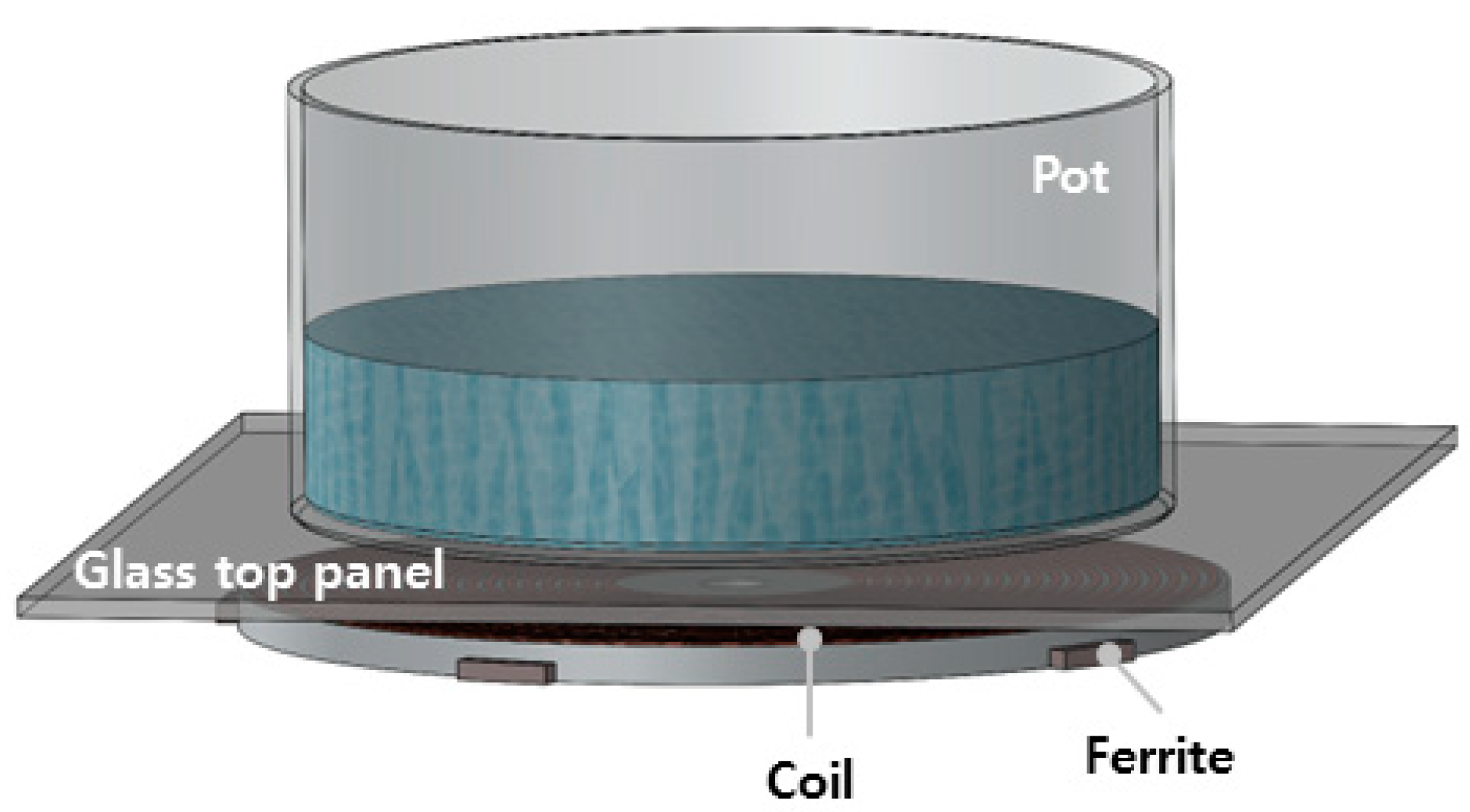
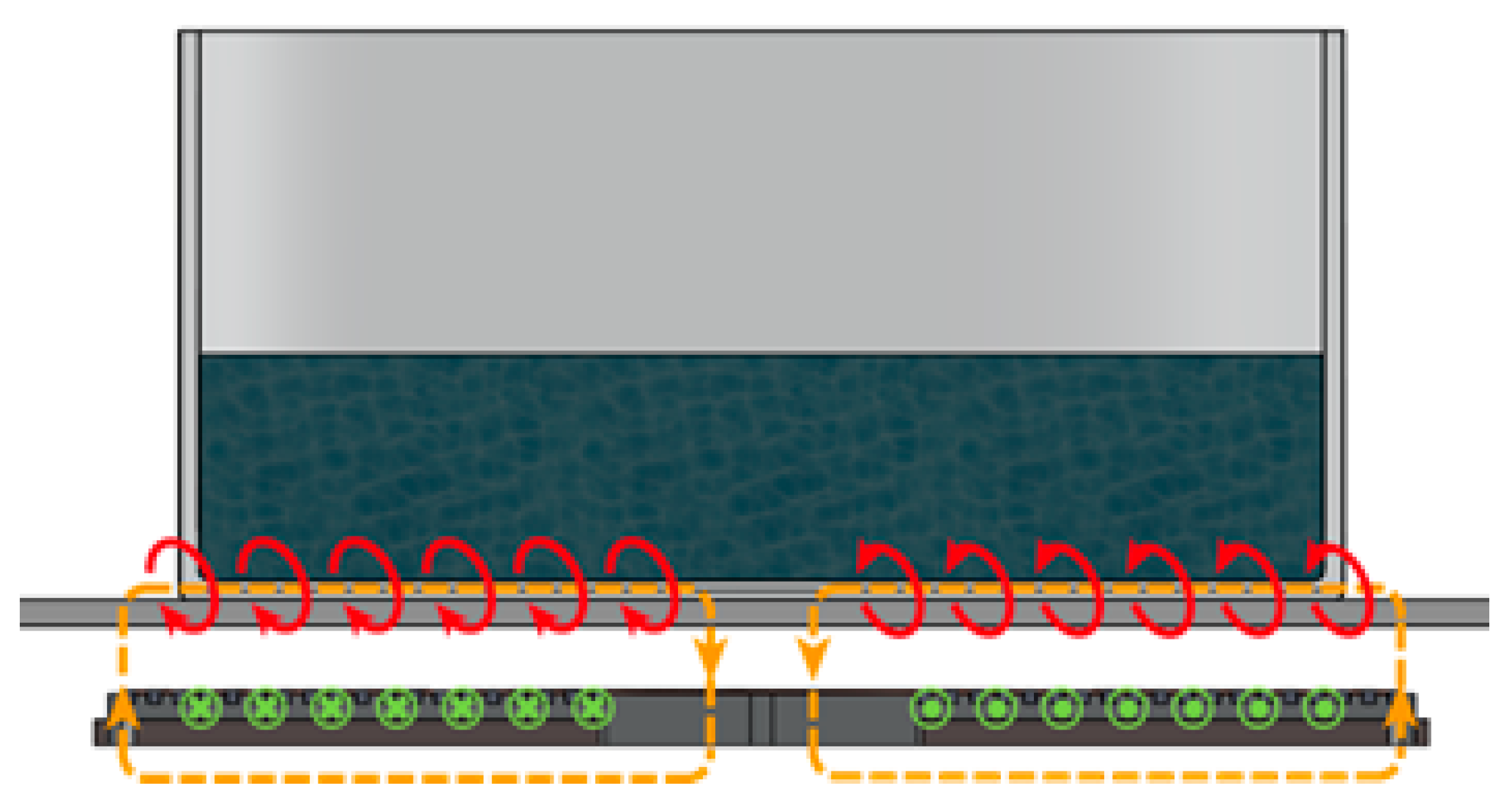
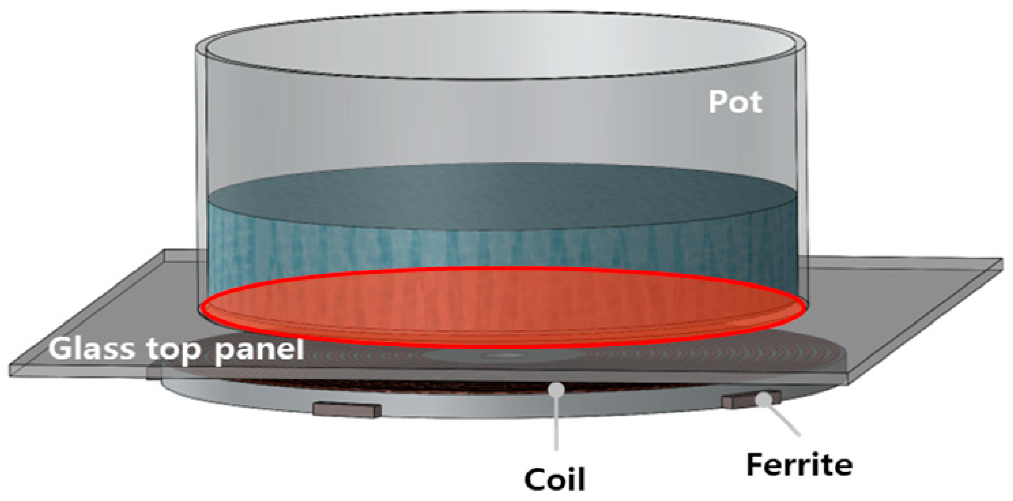
2.1. Operating Principle of the Induction Cooktop

An induction cooktop typically consists of a glass top panel, a coil, and a ferrite core, as illustrated in Figure 1. The heating process of the cookware during cooking relies heavily on Ampere’s Law, Faraday’s Law, and Joule heating. When a current ( J ) is applied to the coil, a magnetic field ( H ) is generated, as described by Equation (1):
× H = J
Ampere’s Law states that the magnetic field generated by an electric current is proportional to the current itself. When a current flows through the coil, a magnetic field is created around it. This generated magnetic field induces a voltage in the cookware through Faraday’s Law, as shown in Equation (2):
× E = B t B = μ H
According to Faraday’s Law, a change in the magnetic field linked with the coil induces a current in the cookware. In an induction cooktop, the primary magnetic field changes generated by the coil induce a current in the cookware placed on top of the cooktop, as illustrated in Figure 2. This induced current generates heat as it passes through the cookware, which has inherent resistance, a phenomenon known as Joule heating. This heat is then transferred to the cookware and its contents, facilitating efficient heating.

2.2. Output Analysis of the Base Model Using FEM

Both the coil and ferrites are crucial components that directly influence the performance of an induction cooktop. This paper analyzes the output and the force generated in the air gap of an induction cooktop with various ferrite shapes. By examining the forces involved in the heating process, we can identify factors contributing to the buzzing noise during operation. To achieve this, we use the finite element method (FEM) to predict the cooktop’s performance. The findings are then utilized to optimize the ferrite cores, aiming to reduce noise. Additionally, since the efficiency of an induction cooktop can be assessed using the cookware, stainless steel 400 series, commonly used in induction cookware, was selected for this study.
Given that the cooktop analysis included eddy current analysis, the skin effect must be considered [37]. To account for the skin effect in the bottom of the cookware, the base is divided into five layers. The mesh for the lowest layer is set to 100,000 elements, while the topmost layer of the cookware base is meshed with 10,000 elements. The ferrite cores, which focus the magnetic field generated by the coil, are meshed with 40,000 elements each. In terms of boundary conditions, to account for leakage flux, the analysis extends 70 mm beyond the cooktop.
The FEM simulations are conducted in 3D, using the model’s symmetric properties to simplify the analysis by only simulating a quarter of the model, as shown in Figure 3. This approach captures the essential characteristics and main features of the system while reducing computational complexity, allowing for efficient and focused analysis of key components or phenomena.
The performance of the induction cooktop is assessed by evaluating the ohmic losses generated at the bottom surface of the cookware. The base model features both large and small ferrites, as illustrated in Figure 4a. The analysis is conducted with a frequency of 27 kHz and a maximum current of 44 A. Figure 4b shows the eddy current analysis results for the base model, displaying the distribution of ohmic loss density at the cookware’s bottom. These results indicate that the losses are not significantly concentrated in the center, suggesting that eddy currents are mainly generated in the mid-region of the cookware rather than at the center or edges. By integrating the ohmic loss density over the volume at the bottom of the cookware, the ohmic loss output for the base model is calculated to be 1638.6 W. This value serves as a reference point for further force analysis.

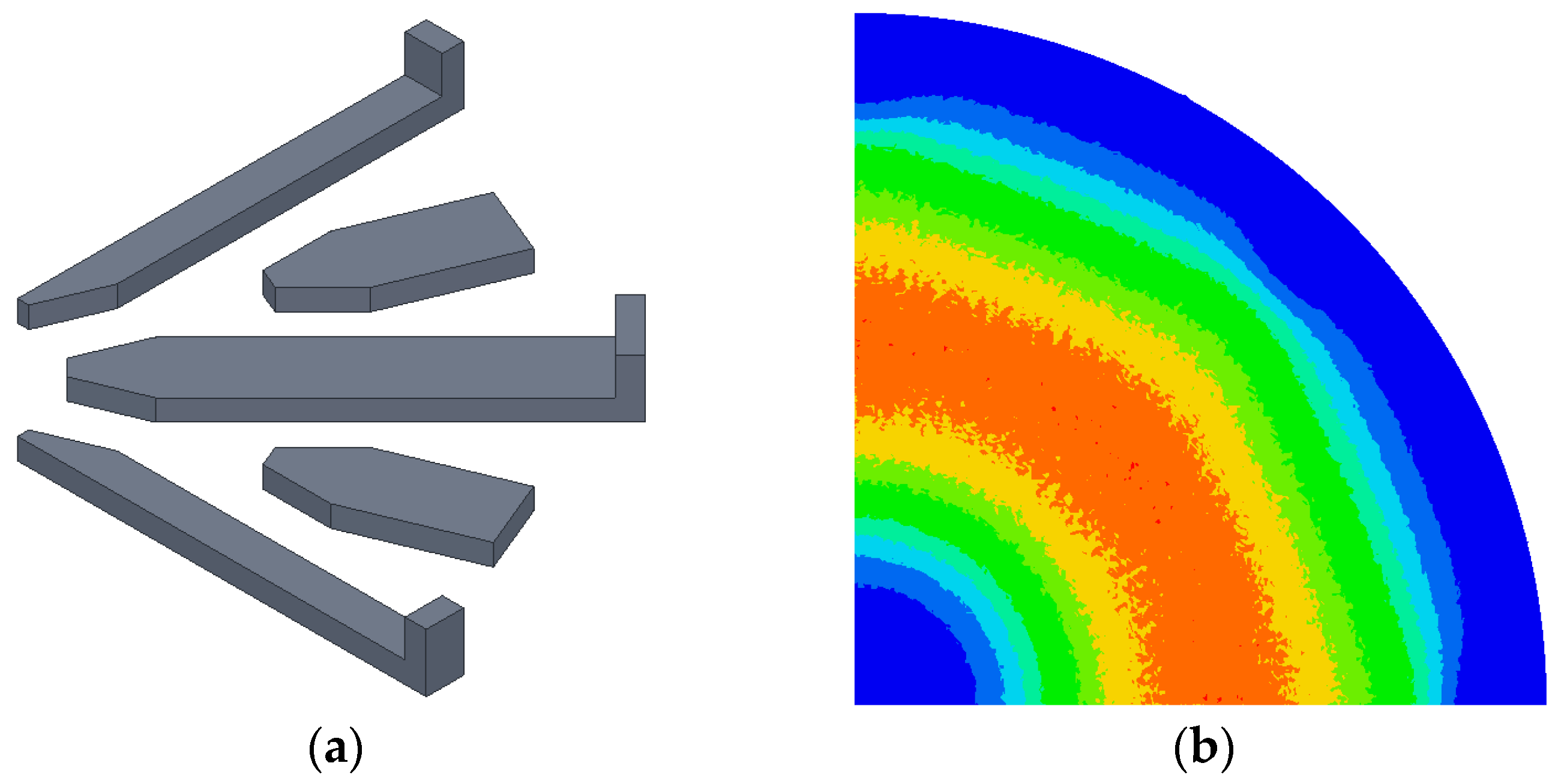
2.3. Ferrite Shape Modification Models

To precisely analyze the electromagnetic forces generated in an induction cooktop due to different ferrite shapes, it is essential to systematically evaluate the impact of each ferrite component. When a current is applied to the coil, a magnetic flux density is generated, which induces eddy currents in the cookware. Therefore, to assess the impact of different ferrite shapes, we analyze the magnetic flux density generated in the air gap.
The magnetic flux density in the air gap was measured at the midpoint between the pot and the ferrite core. Figure 5 illustrates the magnetic flux density at various measurement positions:
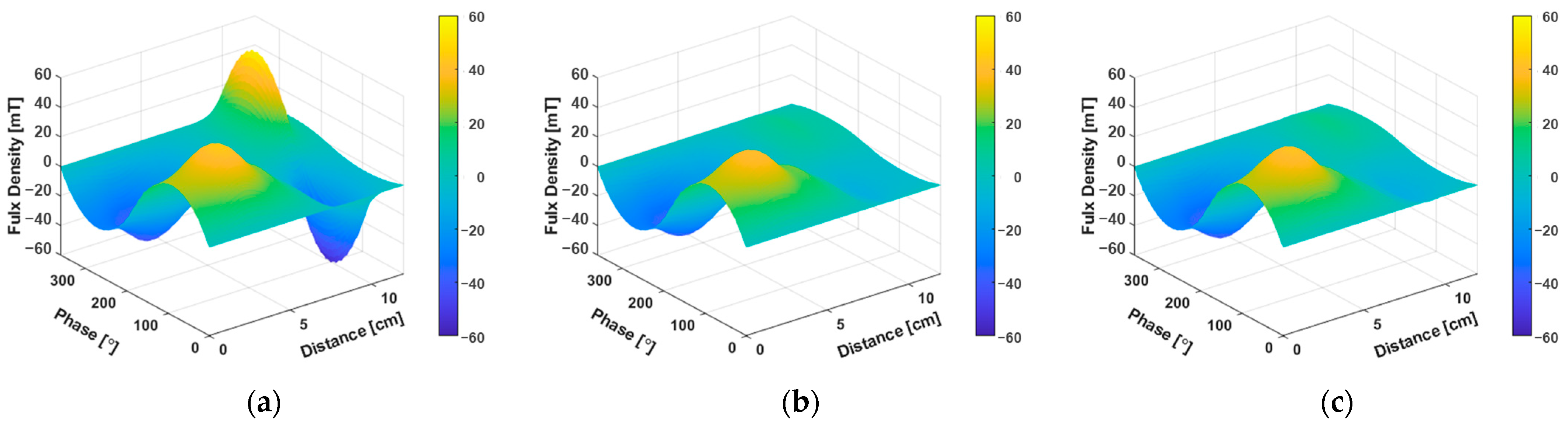
  • Figure 5a: This part shows the large ferrite. The height is higher at the outer part, shortening the air gap and resulting in a higher distribution of magnetic flux density.
  • Figure 5b: This part shows the small ferrite. The ferrite diminishes toward the outer region, leading to a lower magnetic flux density.
  • Figure 5c: This part shows the magnetic flux density in the air gap where there is no ferrite. It is evident that even without the ferrite, magnetic flux density is generated near the center of the cookware.
From these observations, we can conclude that a shorter air gap between the ferrite and the cookware results in a higher magnetic flux density, which can increase the output. To modify the distance between the ferrite and the cookware, we selected and analyzed seven different ferrite shapes, as shown in Figure 6:
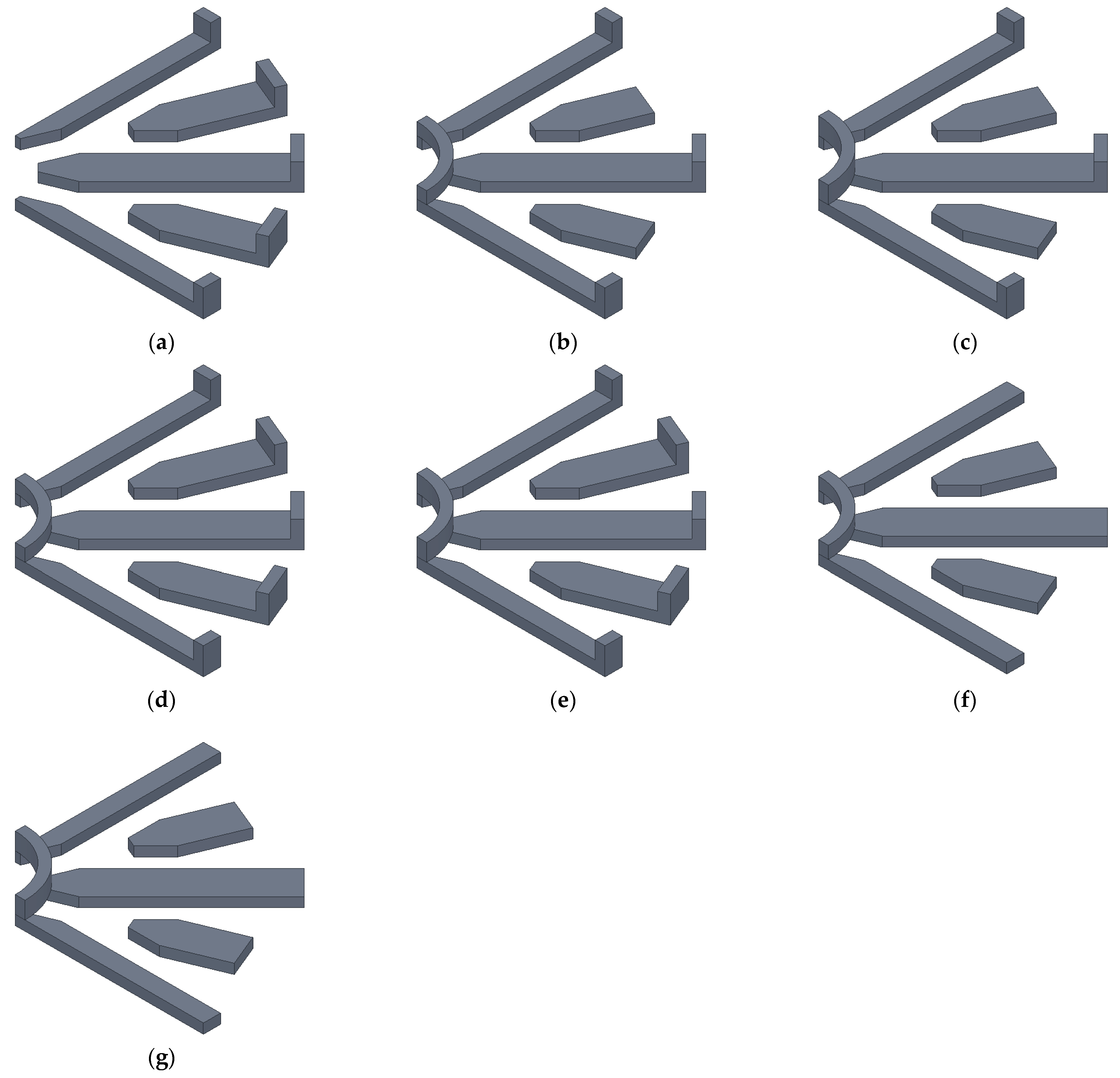
  • Model #1: Based on Figure 5a, since the outer part of the large ferrite is closer to the air gap, increasing the magnetic flux density, the outer part of the small ferrite was modified to match the large ferrite’s shape, thereby shortening the air gap.
  • Model #2 and Model #3: Circular ferrites were added to the inner part of the base model’s ferrite to shorten the air gap, with heights of 5 mm and 7 mm, respectively.
  • Model #4 and Model #5: These models combine Model #1 with Model #2 and Model #3, respectively, to observe the interaction between these shapes.
  • Model #6 and Model #7: These models isolate the effect of the inner ferrite by removing the outer end of the large ferrite from Models #2 and #3, respectively.

2.4. Output Analysis of Ferrite Shape Modification Models Using FEM

To evaluate the impact of ferrite shapes on the output of an induction cooktop, we analyzed various ferrite shape modification models. The output was assessed by calculating the ohmic losses in the cookware, similar to the method used for the base model. The frequency of the input current was set at 27 kHz, with a maximum amplitude of 44 A.
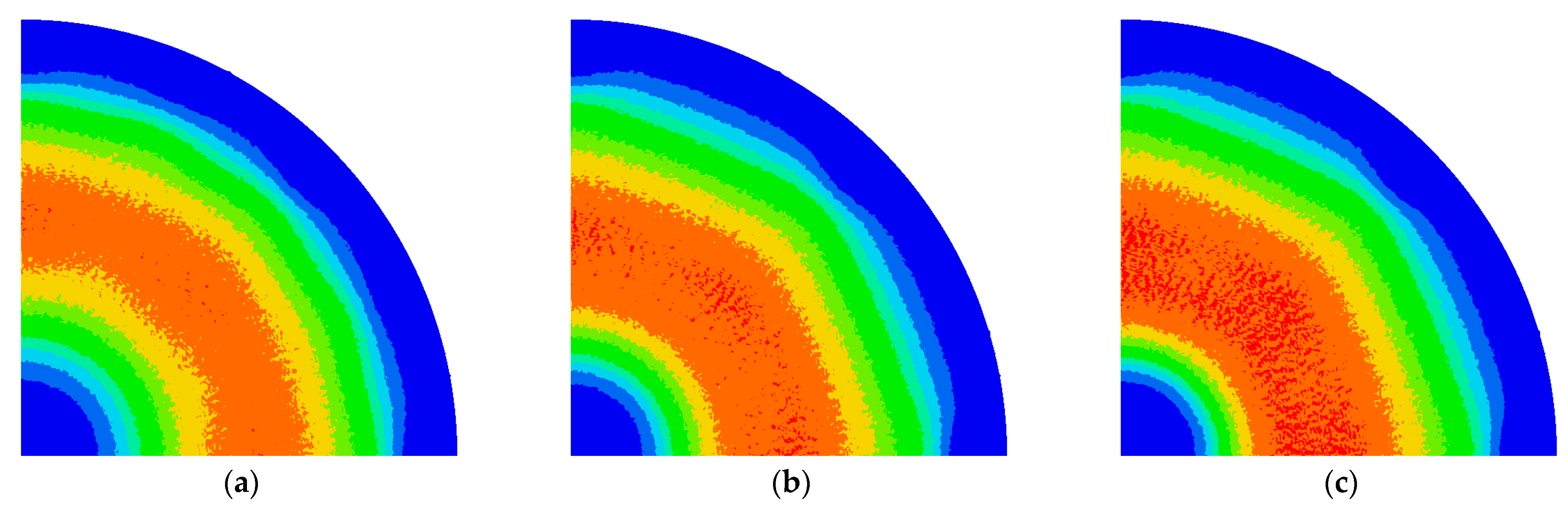
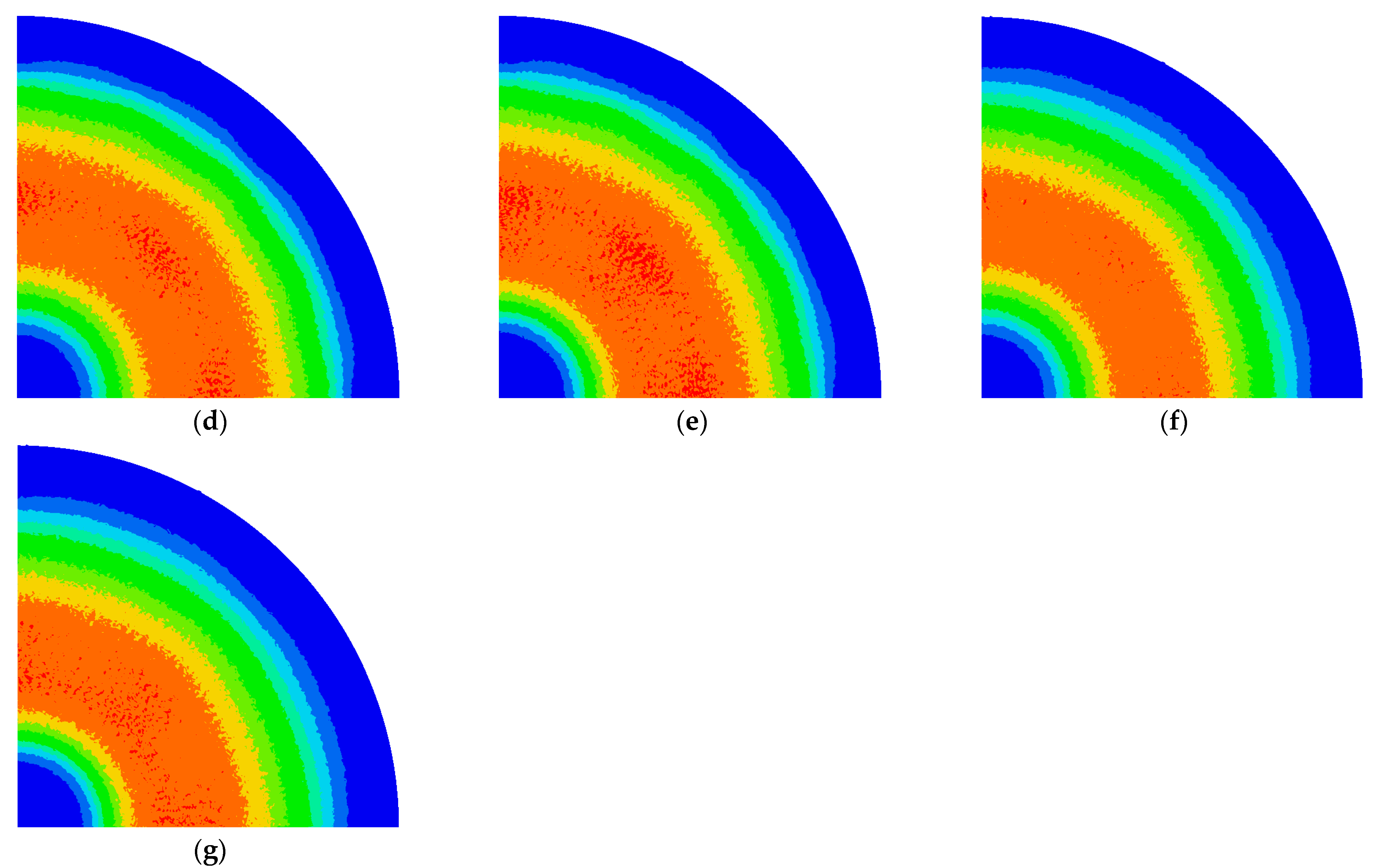
  • Model #1: This model modifies the outer shape of the small ferrite to match the outer shape of the large ferrite. The ohmic loss density distribution for Model #1 is shown in Figure 7a. The calculated output, obtained by integrating the volume of the ohmic loss density, is 1733.7 W, representing a 5.8% increase compared to the base model. Comparing this with the base model’s ohmic loss density distribution in Figure 4b, the loss area has significantly expanded towards the outer region, indicating an increase in output. Thus, altering the outer shape of the small ferrite to match that of the large ferrite enhances the output.
  • Model #2 and Model #3: These models add circular ferrites to the inner part of the base model’s ferrite to shorten the air gap. The ohmic loss density distributions are shown in Figure 7b,c, respectively. The calculated outputs are 1776.7 W for Model #2 and 1833.4 W for Model #3. Model #3, with a shorter air gap, shows a significant increase in output. This is because the addition of the inner ferrite increases the area of the ohmic loss density distribution towards the center of the cookware. Therefore, adding inner ferrites not only results in higher output but also generates more uniform heat compared to the base model.
  • Model #4 and Model #5: These models combine the modifications of Model #1 with those of Models #2 and #3. The outputs, influenced by the newly applied ferrite shapes, increase significantly compared to the previous models. Figure 7d,e show the ohmic loss density distributions for Models #4 and #5, respectively. When the small ferrite is applied, the loss area expands towards the outer part of the cookware. With the addition of the inner circular ferrite, the loss area also increases towards the center. The calculated outputs are 1868.6 W for Model #4 and 1923.6 W for Model #5, showing that the output increase from Model #1 is added to the outputs of Models #2 and #3.
  • Model #6 and Model #7: These models add circular ferrites and remove the outer end of the large ferrite. The ohmic loss density distributions are shown in Figure 7f,g, respectively. The calculated outputs are 1630 W for Model #6 and 1686.0 W for Model #7, showing a slight decrease compared to the base model. The distribution of ohmic loss density indicates a concentration towards the center of the cookware, resulting in a slight reduction in the loss area and, consequently, the output.
Table 1 lists the volumes and outputs of the ferrite for each model. From the perspective of ferrite usage, Model #1 uses more ferrite than Models #2 and #3, but the increase in output is smaller. This suggests that adding inner circular ferrites is more effective at increasing output than modifying the outer small ferrite. The ferrite usage in Model #4 is similar to that of the base model, but the output decreases, indicating that the influence of the outer end of the ferrite is significant when using the same amount of ferrite.
These results show that modifying ferrite shapes significantly impacts the output of induction cooktops. Specifically, adding inner circular ferrites is more effective at increasing output and generating uniform heat, leading to more efficient and reliable cooktops.

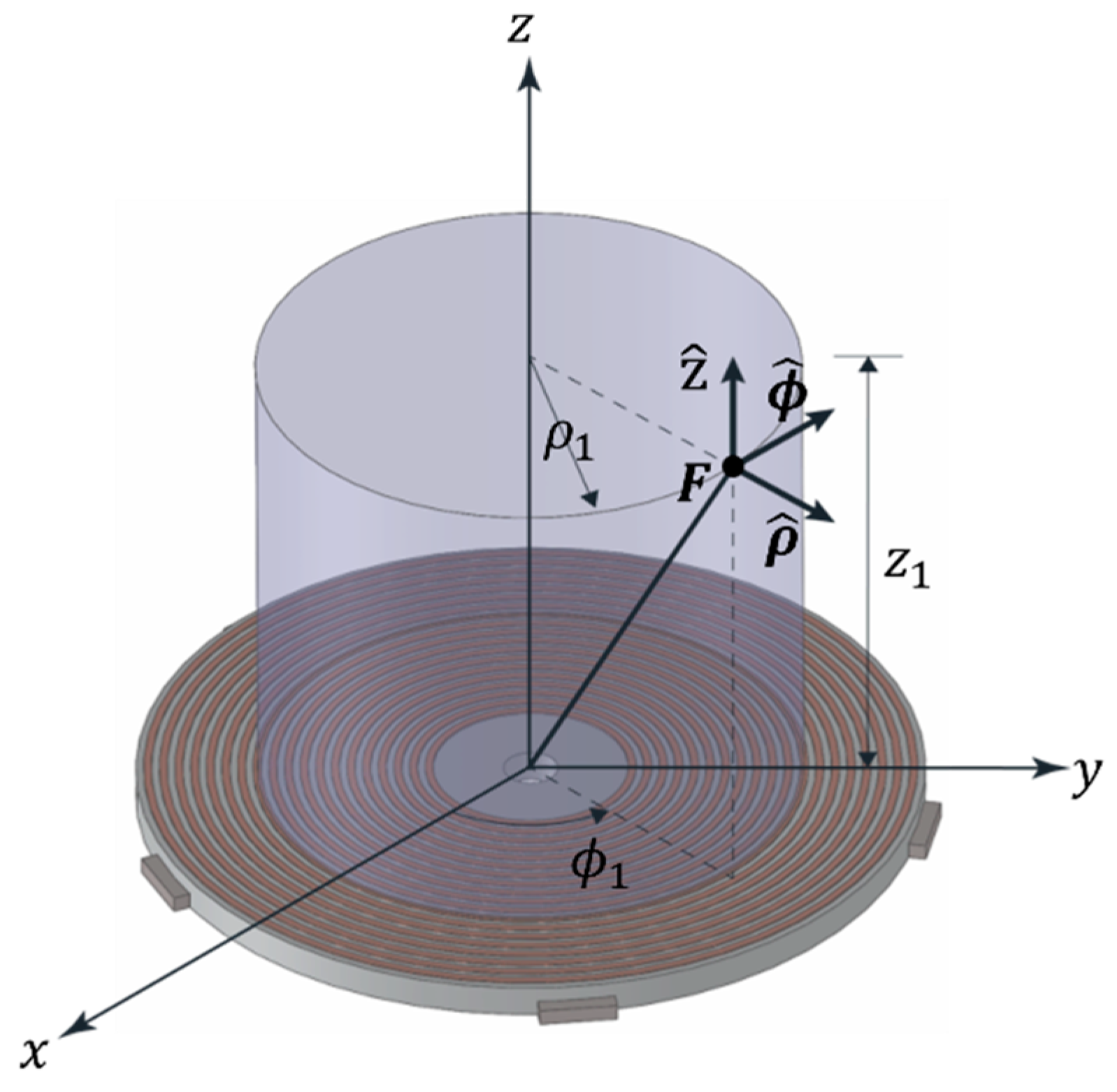
3. Spatial Harmonic Analysis of Forces in the Air Gap

3.1. Forces in the Air Gap of an Induction Cooktop

Figure 8 illustrates the forces that occur in the air gap between the coil and the cooktop surface of an induction cooktop. These forces can be decomposed into their components by calculating the magnetic flux density using the Maxwell Stress Tensor (MST). For an induction cooktop, the force needs to be decomposed into three directions in a cylindrical coordinate system to enable a detailed analysis of the vibrations.
The cylindrical coordinate system consists of three coordinates: radial distance ( ρ ), azimuthal angle ( ϕ ), and height ( z ), which are appropriate for induction cooktops.
The MST in cylindrical coordinates can be expressed in terms of the magnetic flux density as follows: [38]
T = 1 μ 0 B ρ 2 B ϕ 2 B z 2 2 B ρ B ϕ B ρ B z B ϕ B ρ B ϕ 2 B ρ 2 B z 2 2 B ϕ B z B z B ρ B z B ϕ B z 2 B ρ 2 B ϕ 2 2
To determine the total force exerted on an object, MST is integrated over a closed surface surrounding the object. For cylindrical structures in relative motion, the integration surface is located within the air gap between the two objects.
In the induction cooktop, the force is generated in the red circular area shown in Figure 9. We analyze the force in the z-direction, which directly affects the cookware, by calculating the magnetic flux density in the air gap.
When cookware is placed on the induction cooktop, the interaction between the electric and magnetic fields forms a magnetic flux density in the air gap. This magnetic flux density generates a force in the z-direction. Due to the circular shape of both the coil and the cookware, a circular membrane vibration occurs at the bottom of the cookware. This vibration leads to noise, making it essential to understand its characteristics for analyzing the vibrations of the induction cooktop [39,40].
Figure 10 depicts the vibration modes (m, n) of a circular membrane with fixed edges, where m represents the radial nodal lines and n represents the circular nodal lines.
In summary, analyzing the forces in the air gap of an induction cooktop requires an understanding the magnetic flux density and its resulting forces using the Maxwell Stress Tensor in cylindrical coordinates. This analysis allows us to assess the vibrations and potential noise generated by the cookware, which is crucial for improving the performance and user experience of induction cooktops.

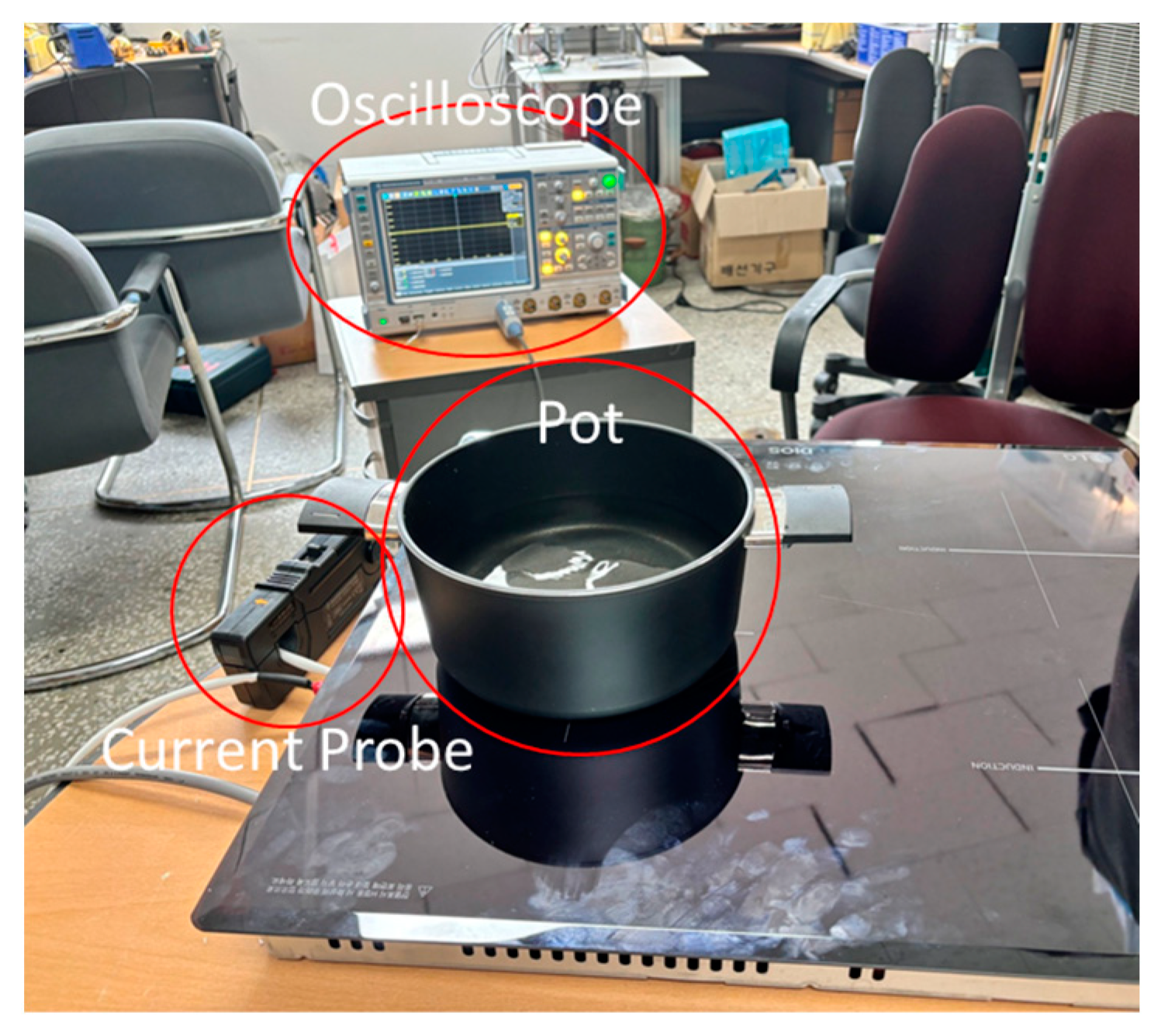
3.2. Noise and Current Measurement of the Base Model

To identify the primary noise frequencies generated by the induction cooktop, we analyzed the noise produced by the base model. Figure 11 illustrates the experimental setup used for measuring current and noise, where the primary equipment included a Rohde & Schwarz (Munich, Germany) RTE 1034 oscilloscope and an RT-ZC10B current probe. For noise measurement, a Brüel & Kjær (Nærum, Denmark) Type 4189-A-031 sound level meter was utilized.
To measure noise, a microphone was positioned 30 cm in front of the cookware. The current was measured by adding an extension to the coil to determine the current applied to it. Figure 12 shows the results of the Fast Fourier Transform (FFT) analysis of the noise generated by the base model. According to this analysis, the noise components at multiples of 120 Hz are significantly higher compared to other frequencies.
The actual waveform of the current is shown in Figure 13, covering a range from 0 s to 0.01667 s. Despite the switching frequency being 38 kHz, the periodicity reveals a 60 Hz component. This 60 Hz current generates a magnetic flux density in the air gap, which in turn produces a force component at 120 Hz. According to Equation (3), the square of the magnetic flux density due to the 60 Hz current generates an excitation force at 120 Hz, resulting in noise components at multiples of 120 Hz. Therefore, by analyzing the force components at 120 Hz through simulation, we can predict the noise associated with different ferrite configurations.
The analysis of noise and current in the base model reveals that the primary noise frequencies are harmonics of 120 Hz. This insight allows us to focus on the 120 Hz component and its harmonics when evaluating and optimizing different ferrite shapes for noise reduction in induction cooktops. By understanding the relationship between current, magnetic flux density, and the resulting force, we can better predict and mitigate the noise generated during operation.

3.3. Spatial Harmonic Analysis Using Air Gap Flux Density
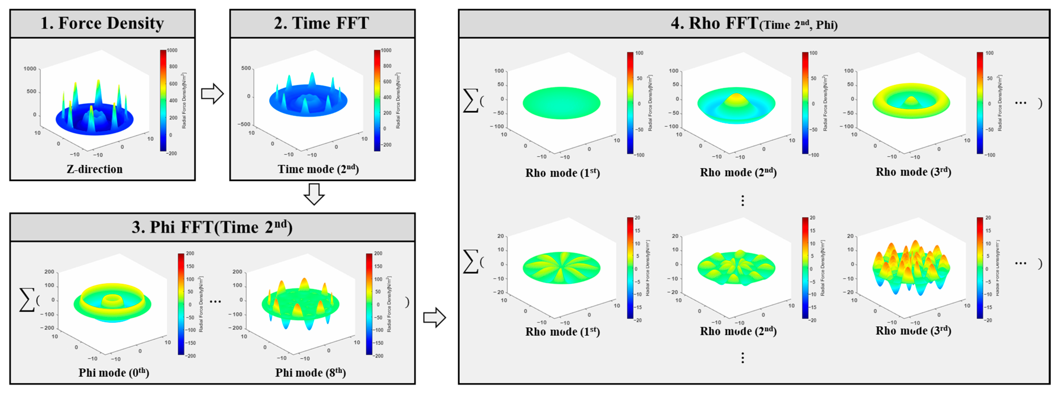
Figure 14 illustrates the process of harmonic analysis of the forces generated in the air gap. To analyze these forces, we calculate them using Equation (3). This is followed by performing FFT over time and subsequently over space. Based on the noise measurement results of the induction cooktop, where multiples of 120 Hz are the primary components, we focus on the second harmonic component of a 60 Hz system over time.
When analyzed spatially, the ferrite shape reveals multiples of the 0th and 8th harmonic components. Finally, we analyze the FFT components in the ρ direction and compare the magnitudes to evaluate the influence of different ferrite configurations. The harmonic analysis steps are as follows:
  • Force calculation using Equation (3):
    Calculate the force generated in the air gap based on the magnetic flux density distribution. This calculation considers the contribution of the electromagnetic fields and the interactions between the coil and the cookware.
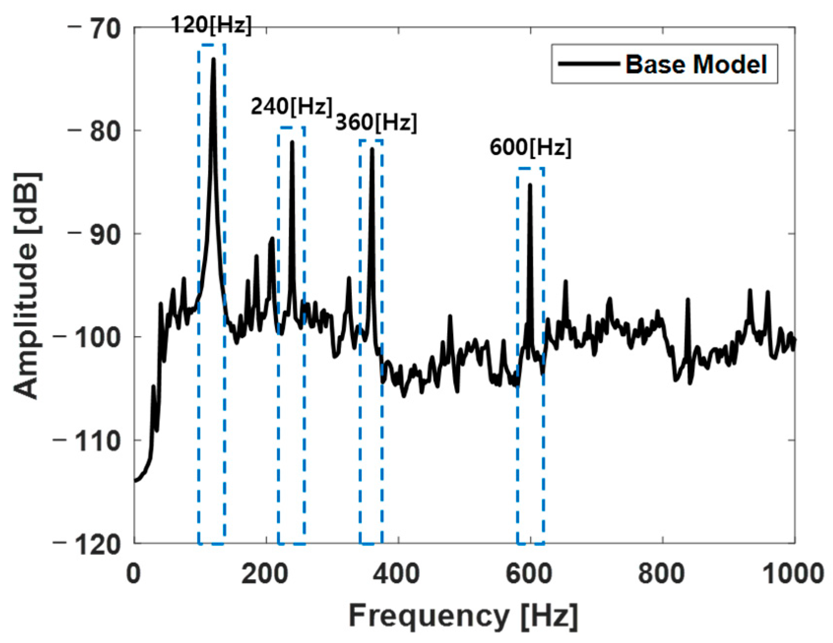
  • FFT over time:
    Perform an FFT on the calculated force over time to identify the dominant frequency components. Given the operational and switching frequency characteristics of the cooktop, we focus on the 2nd harmonic of the 60 Hz component, which is 120 Hz.
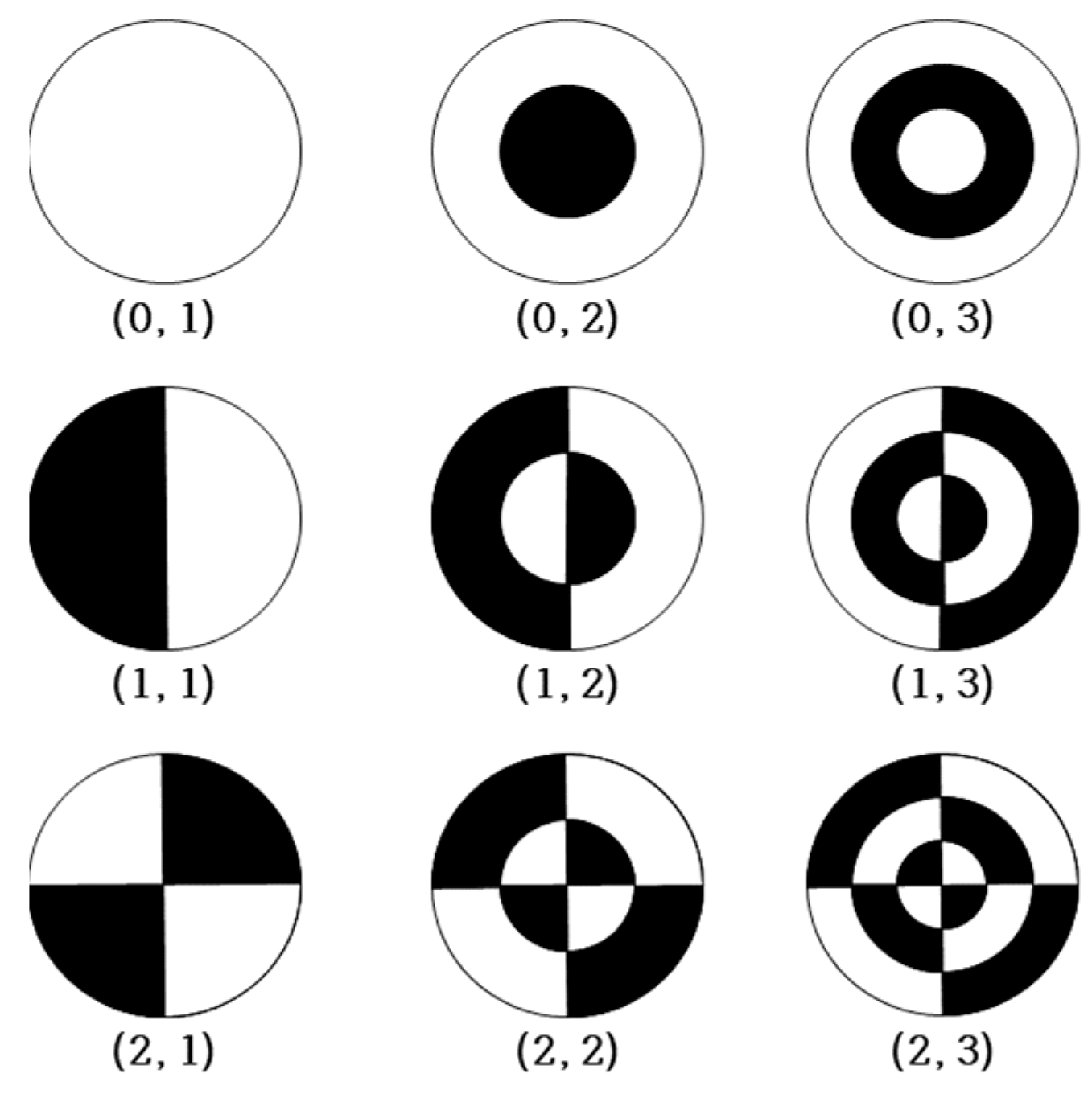
  • FFT over space:
    Conduct an FFT over the spatial distribution of the force. This spatial FFT helps identify the harmonic components introduced by the ferrite shapes. We specifically look for the 0th and 8th spatial harmonic components, as these are prominent in the ferrite shape analysis.
  • Analysis of ρ direction components:
    Analyze the FFT components in the ρ direction (radial direction in the cylindrical coordinate system). By examining these components, we can determine the impact of different ferrite shapes on the overall force distribution and, consequently, on the generated noise.
  • Magnitude comparison:
    Compare the magnitudes of the harmonic components to evaluate the effectiveness of different ferrite configurations. This comparison helps identify which configurations minimize undesirable harmonic components and reduce noise.
By following these steps, we can systematically evaluate the impact of ferrite shape on the forces generated in the air gap and their contribution to noise levels. This approach allows for an optimized design of the ferrite configuration to achieve reduced noise levels in induction cooktops, enhancing their performance and user experience.

3.4. Harmonic Analysis of Spatial Components by Ferrite Shape

A spatial harmonic analysis was conducted for eight ferrite shape models, including the base model. To ensure consistent conditions, the input current was adjusted based on the output of the base model, and the magnetic flux density in the air gap was extracted at equal output levels.
Figure 15 shows the results of the spatial harmonic analysis for the base model. The x-axis and y-axis represent distances, with the center of the cookware set to zero, spanning from −12 cm to 12 cm. The maximum Fz magnitudes of each spatial harmonic component are listed below the figure. The ϕ = 8 harmonic is due to the octagonal symmetry of the induction cooktop, while the ϕ = 0 harmonic results from the central magnetic flux density being high due to the circular coil winding. Similar spatial harmonic analyses are conducted for the modified ferrite shape models and compared to the base model to understand the impact of each shape.
First, we compare the base model with Model #1, where the outer end of the small ferrite is modified. Figure 16a shows this comparison. The x-axis represents the spatial harmonics, and the y-axis represents the magnitude of the maximum z-direction force density. Since Model #1 has a higher output than the base model at the same input, the input current for Model #1 is lower when compared at equal output levels. The air gap length at the center of the cookware remains the same, resulting in a lower force magnitude at ϕ = 0 compared to the base model due to the reduced input current. The modification of the small ferrite shape increases the number of short air gaps from 8 to 16, decreasing the ϕ = 8 component’s magnitude and increasing the ϕ = 16 component’s magnitude.
Next, we compare Models #2 and #3, which have reduced inner air gaps, to the base model, shown in Figure 16b. The reduction in the inner air gap causes a significant increase in the ϕ = 0 component, while input current reduction decreases the ϕ = 8 and ϕ = 16 components. Models #4 and #5 show a substantial increase in output when compared at the same input current, but the changes in the inner ferrite result in a large increase in the ϕ = 0 component. This suggests that the air gap length has a more significant impact than the input current. Similar to Model #1, the modification of the outer air gap pattern results in a decrease in the ϕ = 8 component and an increase in the ϕ = 16 component.
When comparing Models #6 and #7 to the base model, the reduction in the inner air gap length results in a significant increase in the ϕ = 0 component, while the increase in the outer air gap length causes the ϕ = 8 and ϕ = 16 components to be nearly absent. In the 120 Hz spatial harmonic analysis, all models show that the ϕ = 0 component has the highest magnitude and drives unidirectional excitation. Therefore, changes in the ϕ = 0 component will affect the noise levels.
In summary, the spatial harmonic analysis reveals that:
  • Reducing the inner air gap length increases the ϕ = 0 component significantly.
  • Modifying the outer ferrite shape changes the spatial harmonic pattern, shifting from ϕ = 8 to ϕ = 16 components.
  • The ϕ = 0 component dominates the 120 Hz spatial harmonics, influencing the noise characteristics of the induction cooktop.
By understanding these relationships, we can optimize ferrite shapes to minimize noise while maintaining high performance in induction cooktops.

4. Experiments

4.1. Selection of Experimental Models

Figure 17 shows the components used to secure the coil and ferrite for the base model. The prototypes were designed considering structural integrity and fastening requirements within the induction cooktop. Based on the results of the spatial harmonic analysis, reducing only the outer air gap length decreases the ϕ = 0 component, whereas reducing only the inner air gap length significantly increases the ϕ = 0 component. Therefore, the final experimental models selected are Model #8, which reduces the outer air gap, and Model #9, which reduces the inner air gap, as shown in Figure 18.

4.2. Noise Experiments

The same experimental system as shown in Figure 11 was used to measure the noise of Model #8 and Model #9. The results were compared to the base model and are illustrated in Figure 19. In the figure, the black solid line represents the noise of the base model, while the red solid line represents the noise of each experimental model. Table 2 summarizes the noise levels at the main harmonic frequencies of 120 Hz.
For trend analysis, the FEM simulation was simplified. The simulation results showed that the 120 Hz excitation force decreased for Model #8, resulting in an overall reduction in 120 Hz harmonic noise. Conversely, Model #9 exhibited an increase in 120 Hz excitation force, leading to higher levels of 120 Hz harmonic noise.

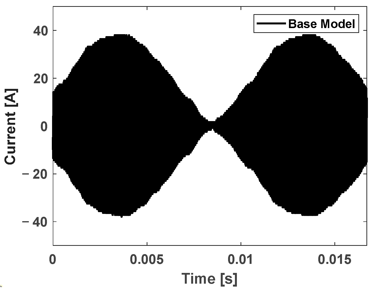
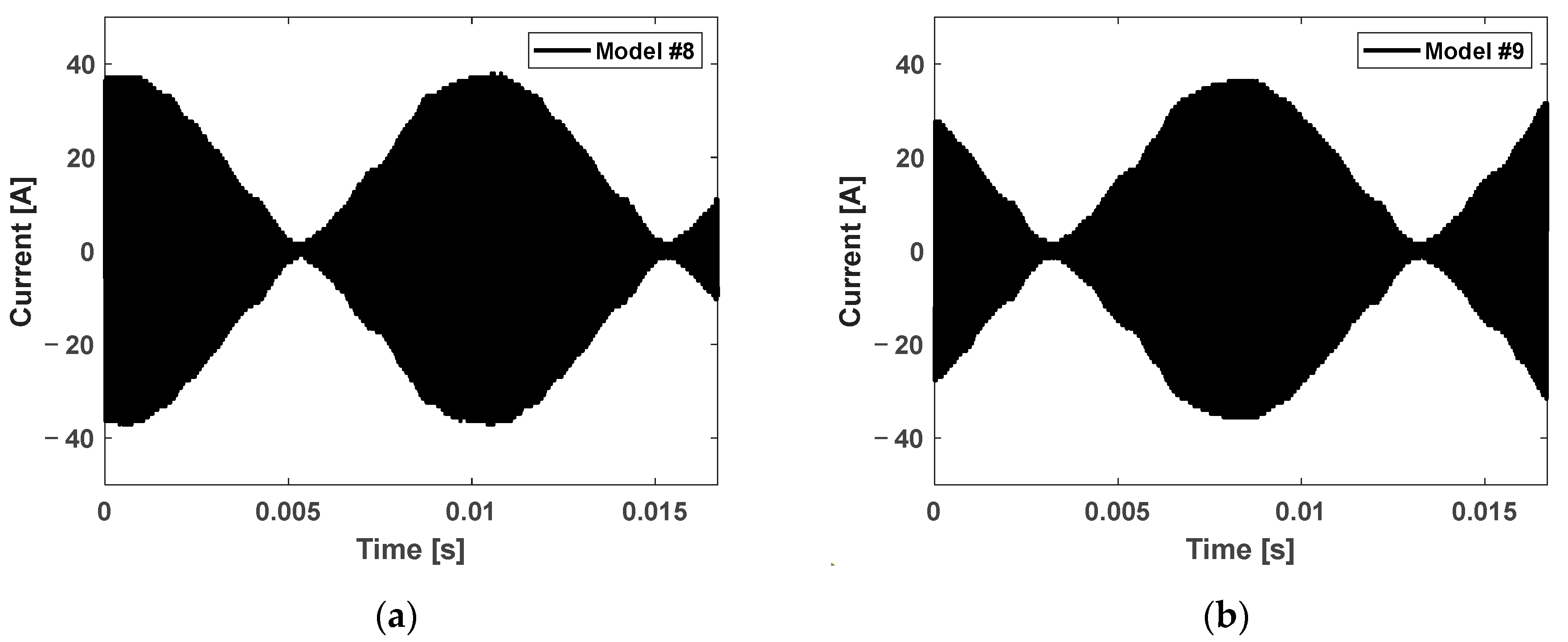
4.3. Current Measurement

Figure 20 shows the current measurement results for Model #8 and Model #9. The heating level of the induction cooktop was set identically, implying that the output power was consistent across models. Based on simulation predictions, a reduction in current for the same output indicates improved efficiency.
The RMS current measurements are as follows:
  • Base Model: 16.74 A (as shown in Figure 13)
  • Model #8: 16.64 A
  • Model #9: 16.16 A
This shows that Model #9’s RMS current is reduced to 94.54% of the Base Model’s RMS current, indicating a significant increase in efficiency due to the reduced inner air gap.

4.4. Summary

The experiments validated the theoretical predictions and simulations. Reducing the outer air gap (Model #8) effectively reduced noise levels without significantly compromising performance. In contrast, reducing the inner air gap (Model #9) significantly improved efficiency but increased noise. These findings are crucial for designing induction cooktops that balance performance and noise considerations. Future work could explore combinations of air gap modifications and advanced materials to further optimize both efficiency and noise characteristics.

5. Conclusions

This study systematically analyzed and experimentally validated the influence of ferrite shape modifications on the performance and noise characteristics of an induction cooktop. The investigation focused on optimizing the air gaps between the ferrites and the cookware, utilizing spatial harmonic analysis and FEM simulations to predict outcomes. The following key conclusions were drawn:
  • Reducing the outer air gap length decreases the ϕ = 0 harmonic component, while reducing the inner air gap length significantly increases the ϕ = 0 component.
  • Models with reduced inner air gaps demonstrated notable performance increases, evidenced by higher power output and lower current requirements.
  • Modifications to the inner air gap had a more substantial impact on the central z-direction force component ( ϕ = 0), contributing to increased performance and higher noise levels.
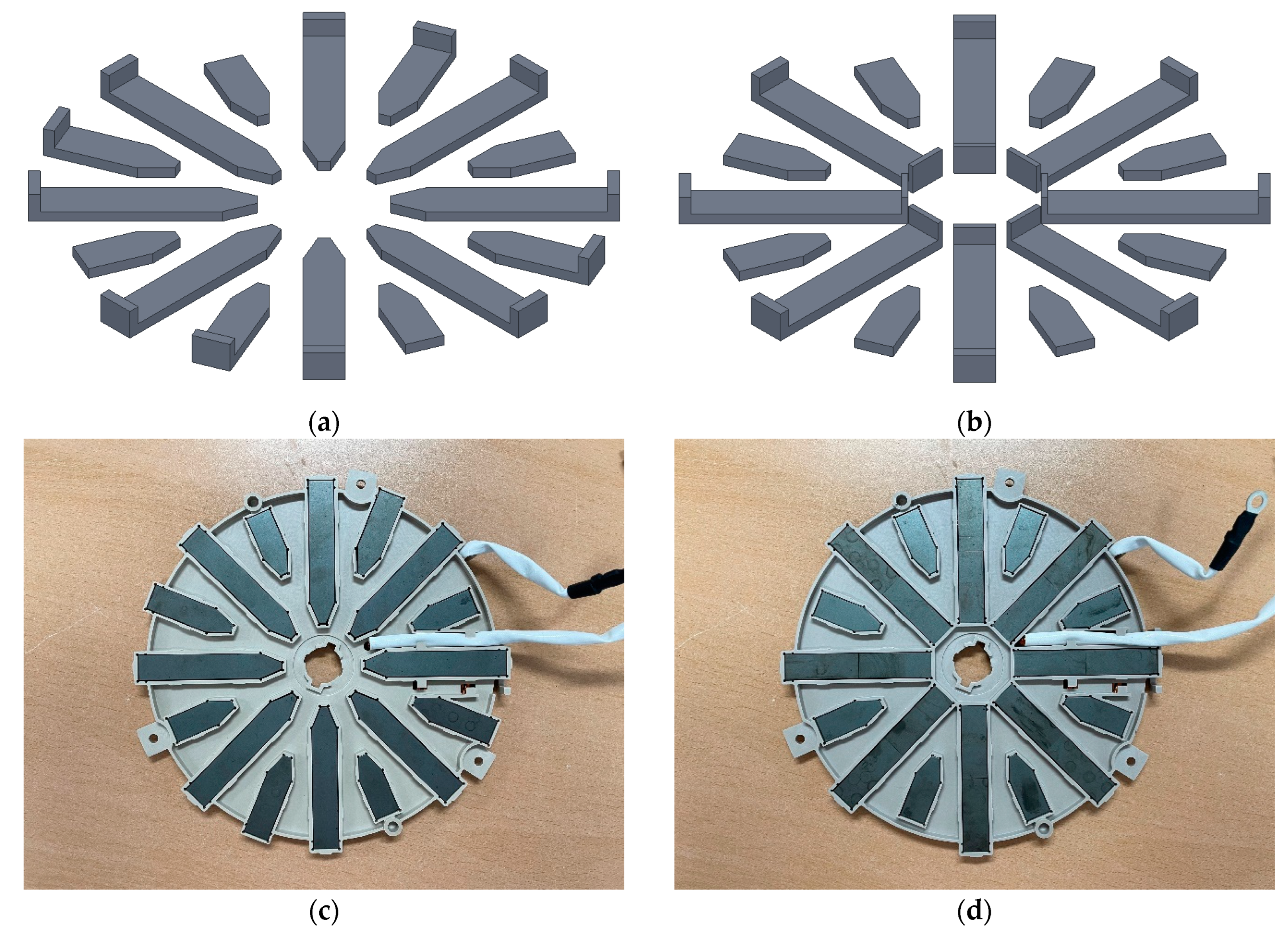
  • Two experimental models were selected based on simulation results: Model #8 (reduced outer air gap) and Model #9 (reduced inner air gap).
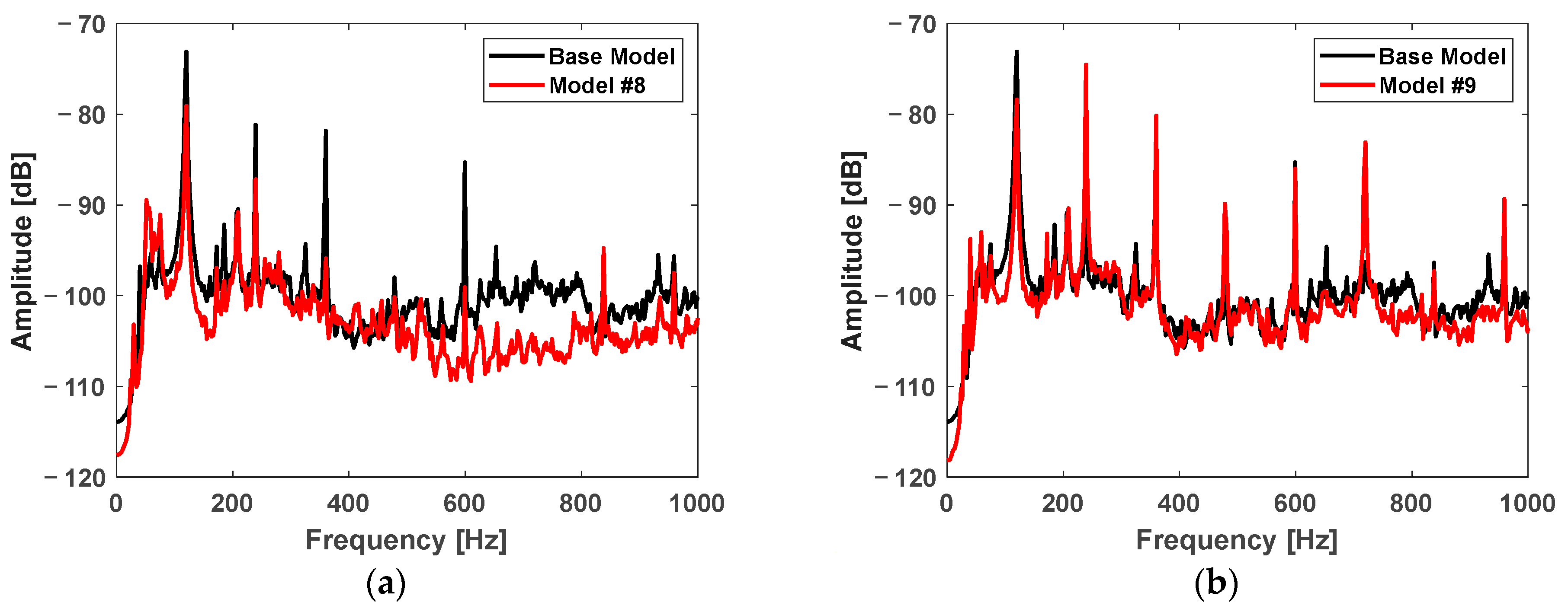
  • Noise measurements revealed that Model #8 reduced 120 Hz harmonic noise components compared to the base model, while Model #9 exhibited increased noise levels due to higher excitation forces.
  • Current measurements confirmed that Model #9 achieved improved efficiency, with RMS current reduced to 94.54% of the base model, indicating significant performance gains from inner air gap reduction.
  • A critical trade-off was observed between performance and noise levels. Inner air gap reduction (Model #9) led to higher efficiency and power output but also increased noise levels due to enhanced harmonic forces.
  • Conversely, outer air gap reduction (Model #8) provided a balanced improvement in noise reduction without drastically compromising performance.
Future research could explore further optimization of ferrite shapes and air gaps, potentially combining modifications to both inner and outer air gaps to achieve a balanced improvement in performance and noise characteristics. Additionally, advanced materials and design techniques could be investigated to reduce noise while maintaining high efficiency, contributing to the development of quieter and more efficient induction cooktops.

Author Contributions

Conceptualization, S.L. and C.L.; Methodology, G.Y. and G.F.L.; Software, S.L., G.Y. and C.L.; Validation, G.F.L., J.-M.K., T.-H.K. and C.L.; Formal analysis, G.Y. and G.F.L.; Investigation, S.L., T.-H.K. and C.L.; Resources, J.-M.K. and T.-H.K.; Data curation, S.L. and G.Y.; Writing—original draft, S.L. and G.Y.; Writing—review & editing, G.F.L., J.-M.K. and C.L.; Visualization, G.F.L.; Supervision, C.L.; Project administration, C.L. All authors have read and agreed to the published version of the manuscript.

Funding

This work was supported by Korea Institute of Energy Technology Evaluation and Planning (KETEP) grant funded by the Korea Government (MOTIE) (20224000000040).

Data Availability Statement

Data are contained within the article.

Conflicts of Interest

Author Tae-Hoon Kim was employed by the company LG Electronics. The remaining authors declare that the research was conducted in the absence of any commercial or financial relationships that could be construed as a potential conflict of interest.

References

  1. Lucia, O.; Acero, J.; Carretero, C.; Burdio, J.M. Induction heating appliances: Toward more flexible cooking surfaces. IEEE Ind. Electron. Mag. 2013, 7, 35–47. [Google Scholar] [CrossRef]
  2. Peters, P.H. A portable cool-surface induction cooking appliance. IEEE Trans. Ind. Appl. 1974, 6, 814–822. [Google Scholar] [CrossRef]
  3. Tanaka, T. A new induction cooking range for heating any kind of metal vessels. IEEE Trans. Consum. Electron. 1989, 35, 635–641. [Google Scholar] [CrossRef]
  4. Dowell, P.L. Effects of eddy currents in transformer windings. In Proceedings of the Institution of Electrical Engineers; IET Digital Library: London, UK, 1966; pp. 1387–1394. [Google Scholar]
  5. Acero, J.; Burdio, J.M.; Barragan, L.A.; Navarro, D.; Alonso, R.; Ramon, J.; Monterde, F.; Hernandez, P.; Llorente, S.; Garde, I. Domestic induction appliances. IEEE Ind. Appl. Mag. 2010, 16, 39–47. [Google Scholar] [CrossRef]
  6. Lucia, O.; Maussion, P.; Dede, E.J.; Burdio, J.M. Induction heating technology and its applications: Past developments, current technology, and future challenges. IEEE Trans. Ind. Electron. 2013, 61, 2509–2520. [Google Scholar] [CrossRef]
  7. Acero, J.; Navarro, D.; Barragan, L.A.; Garde, I.; Artigas, J.I.; Burdio, J.M. FPGA-based power measuring for induction heating appliances using sigma–delta A/D conversion. IEEE Trans. Ind. Electron. 2007, 54, 1843–1852. [Google Scholar] [CrossRef]
  8. Forest, F.; Faucher, S.; Gaspard, J.-Y.; Montloup, D.; Huselstein, J.-J.; Joubert, C. Frequency-synchronized resonant converters for the supply of multiwinding coils in induction cooking appliances. IEEE Trans. Ind. Electron. 2007, 54, 441–452. [Google Scholar] [CrossRef]
  9. Lasobras, J.; Alonso, R.; Carretero, C.; Carretero, E.; Imaz, E. Infrared sensor-based temperature control for domestic induction cooktops. Sensors 2014, 14, 5278–5295. [Google Scholar] [CrossRef]
  10. Jimenez, O.; Lucia, O.; Urriza, I.; Barragan, L.A.; Navarro, D.; Dinavahi, V. Implementation of an FPGA-based online hardware-in-the-loop emulator using high-level synthesis tools for resonant power converters applied to induction heating appliances. IEEE Trans. Ind. Electron. 2014, 62, 2206–2214. [Google Scholar] [CrossRef]
  11. Sarnago, H.; Burdio, J.M.; Lucia, O. High-performance and cost-effective ZCS matrix resonant inverter for total active surface induction heating appliances. IEEE Trans. Power Electron. 2018, 34, 117–125. [Google Scholar] [CrossRef]
  12. Sarnago, H.; Guillen, P.; Burdio, J.M.; Lucia, O. Multiple-output ZVS resonant inverter architecture for flexible induction heating appliances. IEEE Access 2019, 7, 157046–157056. [Google Scholar] [CrossRef]
  13. Sarnago, H.; Lucia, O.; Burdio, J.M. FPGA-Based resonant load identification technique for flexible induction heating appliances. IEEE Trans. Ind. Electron. 2018, 65, 9421–9428. [Google Scholar] [CrossRef]
  14. Singh, S.K.; Agarwal, A.; Kanumuri, T.; Roy, M. Modelling and Controlling of Induction Heating Unit for Induction Cooking Application. J. Phys. Conf. Ser. 2020, 1478, 012010. [Google Scholar] [CrossRef]
  15. Huang, M.-S.; Liao, C.-C.; Li, Z.-F.; Shih, Z.-R.; Hsueh, H.-W. Quantitative design and implementation of an induction cooker for a copper pan. IEEE Access 2020, 9, 5105–5118. [Google Scholar] [CrossRef]
  16. Villa, J.; Dominguez, A.; Barragan, L.A.; Artigas, J.I.; Espanol, J.; Navarro, D. Conductance control for electromagnetic-compatible induction heating appliances. IEEE Trans. Power Electron. 2021, 37, 2909–2920. [Google Scholar] [CrossRef]
  17. Acero, J.; Hernandez, P.; Burdio, J.; Alonso, R.; Barragdan, L. Simple resistance calculation in litz-wire planar windings for induction cooking appliances. IEEE Trans. Magn. 2005, 41, 1280–1288. [Google Scholar] [CrossRef]
  18. Koller, L.; Novák, B. Improving the energy efficiency of induction cooking. Electr. Eng. 2009, 91, 153–160. [Google Scholar] [CrossRef]
  19. Serrano, J.; Acero, J.; Alonso, R.; Carretero, C.; Lope, I.; Burdío, J.M. Design and implementation of a test-bench for efficiency measurement of domestic induction heating appliances. Energies 2016, 9, 636. [Google Scholar] [CrossRef]
  20. Acero, J.; Burdio, J.M.; Barragan, L.A.; Navarro, D.; Alonso, R.; Garcia, J.R.; Monterde, F.; Hernandez, P.; Garde, S.L.I. The domestic induction heating appliance: An overview of recent research. In Proceedings of the 2008 Twenty-Third Annual IEEE Applied Power Electronics Conference and Exposition, Austin, TX, USA, 24–28 February 2008; IEEE: Piscataway, NJ, USA, 2008; pp. 651–657. [Google Scholar]
  21. Carretero, C.; Lucia, O.; Acero, J.; Burdio, J.M. Computational modeling of two partly coupled coils supplied by a double half-bridge resonant inverter for induction heating appliances. IEEE Trans. Ind. Electron. 2012, 60, 3092–3105. [Google Scholar] [CrossRef]
  22. Humza, M.; Kim, B. Analysis and optimal design of induction heating cookers. J. Electr. Eng. Technol. 2016, 11, 1282–1288. [Google Scholar] [CrossRef]
  23. Plumed, E.; Lope, I.; Acero, J.; Burdio, J.M. Domestic induction heating system with standard primary inductor for reduced-size and high distance cookware. IEEE Trans. Ind. Appl. 2022, 58, 7562–7571. [Google Scholar] [CrossRef]
  24. Plumed, E.; Lope, I.; Acero, J. Modeling and design of cookware for induction heating technology with balanced electromagnetic and thermal characteristics. IEEE Access 2022, 10, 83793–83801. [Google Scholar] [CrossRef]
  25. Lucia, O.; Navarro, D.; Guillen, P.; Sarnago, H.; Lucia, S. Deep learning-based magnetic coupling detection for advanced induction heating appliances. IEEE Access 2019, 7, 181668–181677. [Google Scholar] [CrossRef]
  26. Villa, J.; Navarro, D.; Dominguez, A.; Artigas, J.I.; Barragan, L.A. vessel recognition in induction heating appliances—A deep-learning approach. IEEE Access 2021, 9, 16053–16061. [Google Scholar] [CrossRef]
  27. Hironobu, Y.; Natsumi, T. Acoustic Noise of IH Cooker Caused by the Power Supply Noise. J. Biomed. Syst. Emerg. Technol. S 2021, 1, 7. [Google Scholar]
  28. Villa, J.; Artigas, J.I.; Beltran, J.R.; Vicente, A.D.; Barragan, L.A. Analysis of acoustic noise spectrum of domestic induction heating systems controlled by phase-accumulator modulators. IEEE Trans. Ind. Electron. 2019, 66, 5929–5938. [Google Scholar] [CrossRef]
  29. Meng, L.C.; Cheng, K.W.E.; Chan, K.W. Heating performance improvement and field study of the induction cooker. In Proceedings of the 2009 3rd International Conference on Power Electronics Systems and Applications (PESA), Hong Kong, China, 20–22 May 2009; IEEE: Piscataway, NJ, USA, 2009; pp. 1–5. [Google Scholar]
  30. Hu, Q.; Chen, W.; Huang, T.; Chen, Q. The analysis of near-field magnetic leakage on the domestic induction cooker. In Proceedings of the 2014 International Power Electronics and Application Conference and Exposition, Shanghai, China, 5–8 November 2014; IEEE: Piscataway, NJ, USA, 2014; pp. 605–608. [Google Scholar]
  31. Barba, P.; Dughiero, F.; Forzan, M.; Sieni, E. Sensitivity-based optimal shape design of induction-heating devices. IET Sci. Meas. Technol. 2015, 9, 579–586. [Google Scholar] [CrossRef]
  32. Kim, D.-S.; So, J.-Y.; Kim, D.-K. Study on heating performance improvement of practical induction heating rice cooker with magnetic flux concentrator. IEEE Trans. Appl. Supercond. 2016, 26, 1–4. [Google Scholar] [CrossRef]
  33. Balabozov, I.; Brauer, H.; Yatchev, I. Modelling of magnetic concentrators in induction heating systems. In Proceedings of the 2017 15th International Conference on Electrical Machines, Drives and Power Systems (ELMA), Sofia, Bulgaria, 1–3 June 2017; IEEE: Piscataway, NJ, USA, 2017; pp. 453–456. [Google Scholar]
  34. Primiani, V.M.; Kovyryalov, S.; Cerri, G. Rigorous electromagnetic model of an induction cooking system. IET Sci. Meas. Technol. 2012, 6, 238–246. [Google Scholar] [CrossRef]
  35. Acero, J.; Lope, I.; Carretero, C.; Burdio, J.M. Analysis and modeling of the forces exerted on the cookware in induction heating applications. IEEE Access 2020, 8, 131178–131187. [Google Scholar] [CrossRef]
  36. Roberto, S.F.; Ala, G.; Favuzza, S.; Massaro, F.; Zizzo, G. Equivalent circuit modelling of ferrite inductors losses. In Proceedings of the 2018 IEEE 4th International Forum on Research and Technology for Society and Industry (RTSI), Palermo, Italy, 10–13 September 2018; IEEE: Piscataway, NJ, USA, 2018; pp. 1–4. [Google Scholar]
  37. Chen, H.-C.; Huang, K.-H. Finite element analysis of coupled electromagnetic and thermal fields within a practical induction heating cooker. Int. J. Appl. Electromagn. Mech. 2008, 28, 413–427. [Google Scholar] [CrossRef]
  38. Meessen, K.K.J.; Paulides, J.J.H.; Lomonova, E.A. Force calculations in 3-D cylindrical structures using Fourier analysis and the Maxwell stress tensor. IEEE Trans. Magn. 2012, 49, 536–545. [Google Scholar] [CrossRef]
  39. Wah, T. Vibration of circular plates. J. Acoust. Soc. Am. 1962, 34, 275–281. [Google Scholar] [CrossRef]
  40. Yun, G.; Lee, S.; Lukman, G.F.; Lee, C. Investigation of electromagnetic noise in an induction cooktop by examining circular membrane vibration modes in terms of their harmonics. AIP Adv. 2024, 14, 797. [Google Scholar] [CrossRef]
Figure 1. Induction cooktop configuration.
Energies 17 04744 g001
Figure 2. Heat generation process in an induction cooktop.
Energies 17 04744 g002
Figure 3. (a) Simplified simulation model of an induction cooktop; (b) mesh structure of the simulation model.
Energies 17 04744 g003
Figure 4. (a) Ferrite core shape of the base model, (b) ohmic loss density distribution of the base model.
Energies 17 04744 g004
Figure 5. Air gap flux density: (a) large ferrite region, (b) small ferrite region, (c) non-ferrite region.
Energies 17 04744 g005
Figure 6. Ferrite core shapes (a) Model #1, (b) Model #2, (c) Model #3, (d) Model #4, (e) Model #5, (f) Model #6, (g) Model #7.
Energies 17 04744 g006
Figure 7. Ohmic loss density distribution according to ferrite core shape (a) Model #1, (b) Model #2, (c) Model #3, (d) Model #4, (e) Model #5, (f) Model #6, (g) Model #7.
Energies 17 04744 g007aEnergies 17 04744 g007b
Figure 8. Forces in the air gap of the induction cooktop.
Energies 17 04744 g008
Figure 9. Force generation in the induction cooktop.
Energies 17 04744 g009
Figure 10. Vibration modes of a circular membrane with fixed edges.
Energies 17 04744 g010
Figure 11. Experimental setup for measuring current and noise.
Energies 17 04744 g011
Figure 12. FFT analysis of noise from the base model.
Energies 17 04744 g012
Figure 13. Actual current waveform.
Energies 17 04744 g013
Figure 14. Process of harmonic analysis using magnetic flux density in the air gap.
Energies 17 04744 g014
Figure 15. Spatial harmonic analysis of the base model.
Energies 17 04744 g015
Figure 16. Comparison of spatial harmonics for different ferrite shapes: (a) Base vs. Model #1, (b) Base vs. Model #2, 3, (c) Base vs. Model #4, 5, (d) Base vs. Model #6, 7.
Energies 17 04744 g016
Figure 17. Components for securing the coil and ferrite in the base model.
Energies 17 04744 g017
Figure 18. New ferrite model: (a) modeling of Model #8, (b) modeling of Model #9, (c) prototype of Model #8, (d) prototype of Model #9.
Energies 17 04744 g018
Figure 19. Noise comparison: (a) Base Model vs. Model #8, (b) Base Model vs. Model #9.
Energies 17 04744 g019
Figure 20. Current measurement: (a) Model #8, (b) Model #9.
Energies 17 04744 g020
Table 1. Ferrite volume and output of the base model and models with modified ferrite core shapes.
Base ModelModel #1Model #2Model #3
Ferrite Volume [mm3]12,43814,42813,20813,514
100.0%116.0%106.2%108.7%
Output [W]1638.61733.71776.71833.4
100.0%105.8%108.4%111.9%
Model #4Model #5Model #6Model #7
Ferrite Volume [mm3]15,19815,50612,42412,732
122.2%124.7%99.9%102.4%
Output [W]1868.61923.61630.01686.0
114.0%117.4%99.5%102.9%
Table 2. Noise levels at main harmonic frequencies (dB).
Frequency [Hz]Base ModelModel #8Model #9
120−73.09−79.09−78.38
240−81.13−87.16−74.51
360−81.81−95.88−80.14
480−97.98−100.17−89.87
600−85.28−99.05−86.01
720−96.29−104.65−83.09
840−104.50−104.03−102.94
960−95.65−97.50−89.35
Disclaimer/Publisher’s Note: The statements, opinions and data contained in all publications are solely those of the individual author(s) and contributor(s) and not of MDPI and/or the editor(s). MDPI and/or the editor(s) disclaim responsibility for any injury to people or property resulting from any ideas, methods, instructions or products referred to in the content.

