Abstract
Structural materials in fast reactors with harsh radiation environments due to high energy neutrons—compared to thermal reactors—potentially suffer from a higher degree of radiation damage. This radiation damage can change the thermophysical and mechanical properties of materials and, as a result, alter their performance and effective lifetime, in some cases leading to their disintegration. These phenomena can jeopardize the safety of fast reactors and thus need to be investigated. In this study, the effect of radiation damage on the vessels of molten salt fast reactors (MSFR) was evaluated based on two fundamental radiation damage parameters: displacement per atom (dpa) and primary knock-on atom (pka). Following the previous part of this article (Parts 1 and 2), an iMAGINE reactor core design (University of Liverpool, UK—chloride-based salt fuel system) and an EVOL reactor core design (CNRS, Grenoble, France, fluoride-based salt fuel system) with stainless steel and nickel-based alloy material vessels, respectively, were considered as case studies. The SPECTER and SPECTRA-PKA codes and a PTRAC card of MCNPX, integrated with a module which has been developed in MATLAB, named PTRIM and SRIM-2013 (using binary collision approximation), were employed individually to calculate and compare dpa and PKA (this master module containing all three tools has been appended to the iMAGINE-3BIC package for future use during reactor operations). Additionally, SRIM-2013 was applied in a 3D simulation of a radiation damage map on a small sample of vessels based on the calculated PKA. Our results showed a higher degree of radiation damage in the iMAGINE vessel compared to the EVOL one, which could be expected due to the harder neutron flux spectrum of the iMAGINE core compared to EVOL. In addition, the nickel alloy vessel showed better radiation damage resistance against high energy neutrons compared to the stainless steel one, although more investigations are required on thermal neutrons and alloy corrosion mechanisms to determine the best material for use in MSFR vessels.
1. Introduction
Structural materials in nuclear power plants are subjected to extreme conditions, including high temperatures, intense radiation fields, and corrosive environments, which can significantly affect their mechanical and physical properties over time. Understanding the mechanisms of radiation damage is essential for ensuring the safety, reliability, and longevity of nuclear reactors. Considering the benefits of a fast neutron energy spectrum for GenIV nuclear power plants [1], which experience a higher level of radiation damage (more dpa as a fundamental damage mechanism) to their components compared to thermal reactors, we set out to demonstrate the importance of radiation damage evaluations for the development of safety criteria for such reactors [2].
Radiation damage primarily results from the interaction of energetic particles—such as neutrons, gamma rays, and charged particles—with the atoms in the structural materials. These interactions can displace atoms from their lattice positions, create point defects and dislocation loops, and lead to changes in their microstructures, such as void swelling, phase transformations, and radiation-induced segregation [3]. Such microstructural changes can degrade the mechanical properties of materials, including their strength, ductility, and fracture toughness, and can also affect their thermal and electrical conductivity.
The study of radiation damage is a multiscale, multiphysics problem which involves a combination of experimental techniques, such as transmission electron microscopy (TEM) and ion irradiation experiments [4,5,6], as well as computational modeling, including molecular dynamics (MD) simulations [7,8,9,10,11,12,13,14,15,16,17,18,19,20,21] and kinetic Monte Carlo methods [22,23,24,25,26,27,28,29]. Some studies have employed hybrid methods, which integrate models and experiments to predict radiation damage in materials and changes in their physical properties, and additionally, to prove the reliability of the results [30,31]. These approaches help elucidate the fundamental processes of defect formation and evolution and predict the long-term behavior of materials under irradiation.
Scanning electron microscopes (SEMs) [32] and transmission electron microscopes (TEMs) [33] are two of the standard tools for imaging the microstructure, morphology, and internal structure of materials that are widely employed experimentally for evaluations of radiation damage. In a recent study, Wilczopolska et al. [4] employed SEM and Raman spectroscopy to analyze the radiation damage on nuclear grade graphite, which is mostly used in GenIV nuclear power plants, e.g., very high-temperature gas cooled reactors or thermal molten salt reactors. They found strong structural disorder in graphite irradiated with Ar+ and concluded that the microstructural evolution of the nuclear graphites aligned with the structural deterioration in a stepwise character. In another interesting study, the JANNuS platform (Joint Accelerators for Nanosciences and Nuclear Simulation) was coupled with a TEM, offering the capability of in situ observation of microstructural and radiation damage at the nanoscale [5]. The results of different experimental radiation damage analyses employing JANNuS can be found in the published literature.
Today, developments in computational science and the availability of high-performance computers (HPCs) have provided the required flexibility to employ complex simulation models and methods in science. Molecular dynamics (MD) [34] simulation tools are among the most interesting approaches to be applied in the simulation of material behavior and radiation damage. The backbone of the MD method is simply to solve Newton’s equations of motion for a (large) number of interacting particles. GROMACS [35], NAMD [36], LAMMPS [37], and AMBER [38] are the most popular software/codes to have been developed based on MD methods for material science. These tools have been applied in a vast number MD-based studies and radiation damage analyses [7,8,9,10,11,12,13,14,15,16,17,18,19,20,21]. Most of these research studies have used MD simulations to identify the primary knock-on atoms as the fundamental parameter of the radiation damage cascade in different materials [8,15,18]. Given the high cost of simulations by MD codes (in terms of CPU and RAM), these studies are usually satisfied with PKA simulations, and no more tracking of secondary knock-on atoms and their cascades are considered. Fuel-clad light water reactors (usually Zircaloy) and their pressure vessels (usually stainless steel) are among the most analyzed materials in this category, as their radiation damage can affect the safety of nuclear power plants [14,15]. In the past, due to the changing paradigm of nuclear energy and the development of fusion nuclear power plant technologies, some researchers have focused on using MD simulations for fusion-dedicated nuclear materials and radiation damage resistance in harsh fusion environments to find the best candidates for materials [7,14,16,19,21].
Probabilistic simulations are one of the most reliable methods that can be used in parallel with deterministic ones and, in some circumstances, have the benefit of more flexibility (especially in terms of overcoming the difficulties of geometry and coordination). The Monte Carlo (MC) method [39] is one of the most widely employed probabilistic methods for radiation damage and reactor core simulations, relying on repeated random sampling to obtain numerical results. In this regard, MC-based codes were developed for two main purposes in the nuclear and materials engineering community: (i) for nuclear reactor core design, source term calculations, and radiation shielding, which can also be used for radiation damage calculation coupling with other modules; and (ii) codes dedicated to radiation damage sourcing from different particles. While MCNP/X [40,41], OpenMC [42], and SERPENT [43] belong to the former group, codes such as SPECTER [44], SPECTRA-PKA [45], FISPACT [46], and SRIM [47] are more dedicated to the latter. In the majority of studies employing MC methods, neutron/ion fluxes are calculated using a code dedicated to the former group (i); then, PKA and subsequent cascades will be followed by one of the codes belonging to the latter (ii). In a recent study, Lovecký et al. employed MCNP6 and SERPENT2 combined with arc-dpa and NRT-dpa [48] models to calculate the radiation damage on the fuel cask of a VVER-440 system [22] and to assess if radiation damage to the cask would represent a major issue in its lifetime. In another study, a package was developed by Noori-kalkhoran et al. [25] to evaluate the effect of radiation damage on the zircaloy clad of a VVER-1000 system. They employed a MCNPX neutron flux with SPECTER, SPECTRA-PKA, and SRIM to simulate the PKA and calculate the dpa on the fuel clad. Neutron KERMA factors and radiation damage cross-sections were calculated based on different neutron cross-section libraries using NECP-Atlas [49] and NJOY codes [50].
Few studies on radiation damage have applied hybrid experimental–theoretical methods to validate the radiation damage results or predict material property changes induced by radiation damage. It should be noted that the final goal of all radiation damage simulations/calculations is to predict how this damage alters the mechanical properties of materials during long-term operations. Kirk et al. employed a computer model of irradiation defect production closely coordinated with TEM and in situ ion irradiation of molybdenum at 80 °C over a range of doses, dose rates, and foil thicknesses [30]. Noori-kalkhoran et al. [31] developed a micromechanical model of the changes in electrical conductivity of zircaloy induced by neutron irradiation. The simulated values of dpa were connected to a change in the experimental properties of zircaloy’s conductivity using experimental curves, which showed promising results.
Research in the field of radiation damage is crucial for the development of advanced materials that can withstand the harsh conditions inside nuclear reactors. This includes designing alloys with improved radiation resistance, developing coatings that protect against corrosion and radiation, and employing novel materials such as ceramics and composites. Enhancing our understanding of radiation damage also supports the safe operation of existing nuclear power plants and the design of next-generation reactors, additionally contributing to the sustainable and efficient production of nuclear energy.
In this study, the methodology introduced in [25] has been developed as a new module of the iMAGINE-3BIC package [51], which enables it to calculate radiation damage based on PKA and dpa over the lifetime of molten salt-fast reactors (MSFRs). The iMAGINE reactor core design (University of Liverpool, UK—chloride-based salt fuel system) [52] and EVOL reactor core design (CNRS, Grenoble, France, fluoride-based salt fuel system) [53] were considered as case studies to compare radiation-induced damage to their vessels as structural materials, following previous studies [51,54]. The outcome helps identify the more appropriate material (i.e., stainless steel vs. nickel-based alloy) for MSFR structures from the point of radiation damage, although more investigations are required to evaluate the corrosion and high kinetic energy particle damage to structural materials, i.e., reactor vessels.
2. Methodology
The principals of computer-based radiation damage simulation at atomic scales began with the efforts of Norgett, Robinson, and Torrens in 1975 [55] to propose a simple procedure for calculating the number of atomic displacements produced in a damaging cascade by a primary knock-on atom of known energy. They proposed their modified “NRT-dpa” model [48] based on the comparison of five available approaches in 1975 for calculating the damage to a solid by a primary recoil atom of a given initial energy, i.e., (i) the Kinchin-Pease model [56], (ii) the half-Nelson model [57], (iii) Binary collision simulations using a threshold model [48,58], (iv) binary collision simulations using the vacancy capture model [59], and (v) cascade simulation by molecular dynamics [60]. Later on, most of the developments in models and codes were based on one of these approaches.
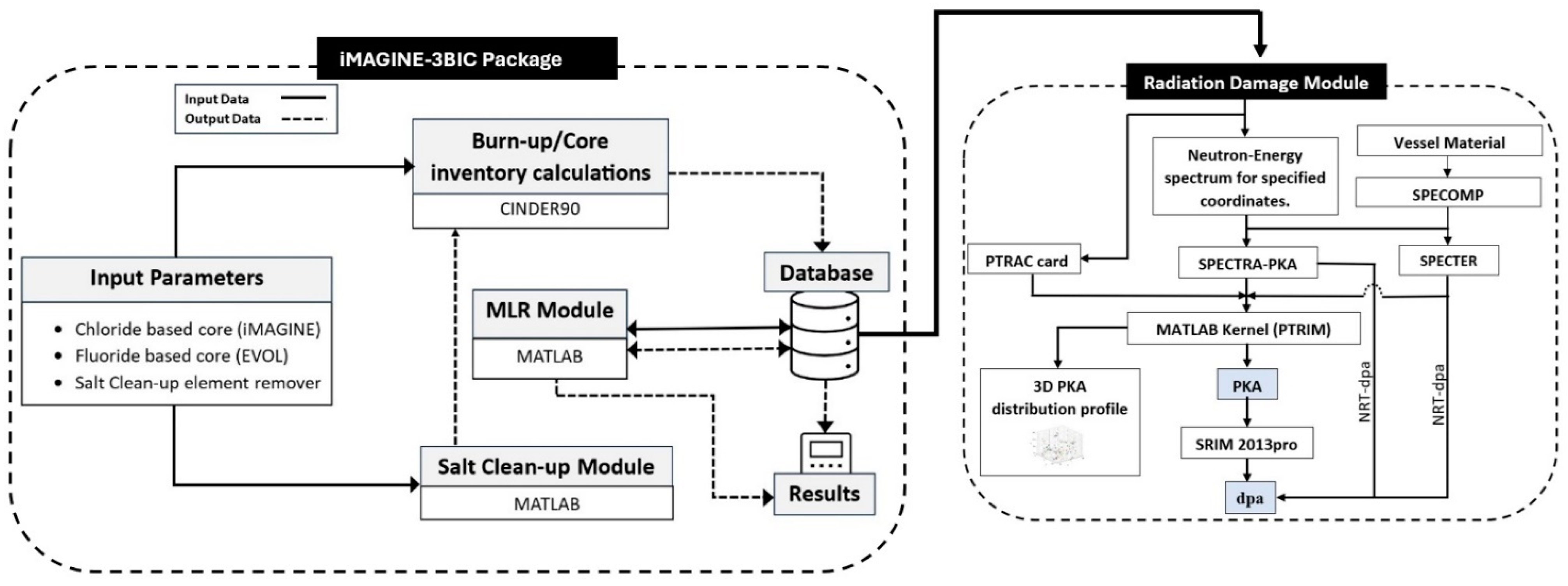
In this manuscript, a similar approach to that found in [25] has been developed as a module and appended to the iMAGINE-3BIC package to simulate radiation damage based on PKA and dpa during the lifetime of MSFRs. Figure 1 depicts the module algorithms and functional blocks. As seen in this figure, the neutron-energy spectrum at the desired coordinate as a function of time “Flux(E,t)”, which was archived in the database of IMAGINE-3BIC package [51], is used as the main input to the radiation damage module. Three different approaches are employed to calculate the primary knock-on atoms (PKA). In the first approach, SPECOMP code [61] is employed to generate the displacement damage cross sections of reactor vessel materials (hereafter referred to as stainless steel and Ni alloy), as SPECTER code [62] uses these cross sections to calculate the PKA and dpa of compounds. When SPECOMP is executed, two files are created. The file SPECOMP.OUT contains details about the calculations that have been performed.
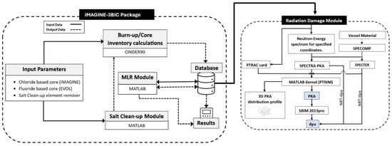
Figure 1.
Developed radiation damage module and its connection to the IMAGINE-3BIC [50].
The file COMPOUND.OUT is appended to the file COMPOUND.DAT from SPECTER to perform the calculations whenever SPECTER is executed, also for vessel materials. SPECTER computer code uses master libraries of displacement cross sections, recoil distributions, and other nuclear data to calculate the PKA and dpa for the elements and compounds in its library. In the second approach, SPECTRA-PKA [45] is used to calculate the PKA, and subsequently, the results of PKA are fed to the PTRIM module (developed in MATLAB) to prepare the input of the SRIM-2013 for damage calculations. SPECTRA-PKA is a command-line driven program for calculating the expected primary knock-on atom (PKA) spectra for a given target nuclide under neutron or charged particle irradiation. It was developed as a part of the FISPACT-II package [63]. The third approach mostly relies on the PTRAC card of MCNP/X and the “PTRIM” sub-module developed in MATLAB [25]. PTRIM processes the PTRAC file of MCNPX, SPECTER, and SPECTER- PKA outputs and prepares the SRIM (TRIM module) input file [25]. The PTRAC card generates an output file (default name PTRAC) of user-filtered particle events. The PTRAC card is read by PTRIM and, based on the desired event IDs and the coordination of events, refines the collision events which make the atom knockouts from its lattice. Then, these data are categorized in the PTRIM database to make the PKA spectrum. More detailed information on the PTRIM process and data compilation can be found in [25]. A new feature has been added to PTRIM sub-module in comparison to [25] which refines the collision data and makes the 3D profile of PKA distribution based on their MAT number coordinate, thereby facilitating PKA detection and interpretation as a function of the materials. As the last step of the radiation damage module, SRIM-2013 processes the PKA data compiled by the PTRIM module (in SRIM/TRIM input format) to simulate the radiation damage, yielding 3D target damage and ionization profiles.
3. Results and Discussion
Radiation damage in the harsh, high-energetic (fast) neutron environment of fast reactors needs to be evaluated to understand the damage mechanisms. Mechanisms of macro-scale radiation damage in fast reactors can usually be seen as void swelling, irradiation growth, irradiation hardening, irradiation creep, irradiation embrittlement, and H/He embrittlement. These damage mechanisms originate from two fundamental micro-mechanisms: atomic displacement and transmutation. Therefore, the calculation of displacement per atom (dpa) and primary knock-on atoms (PKA) is of fundamental importance to predict the amount of radiation damage, although some multi-scale simulations are required to convert it to macro-parameters.
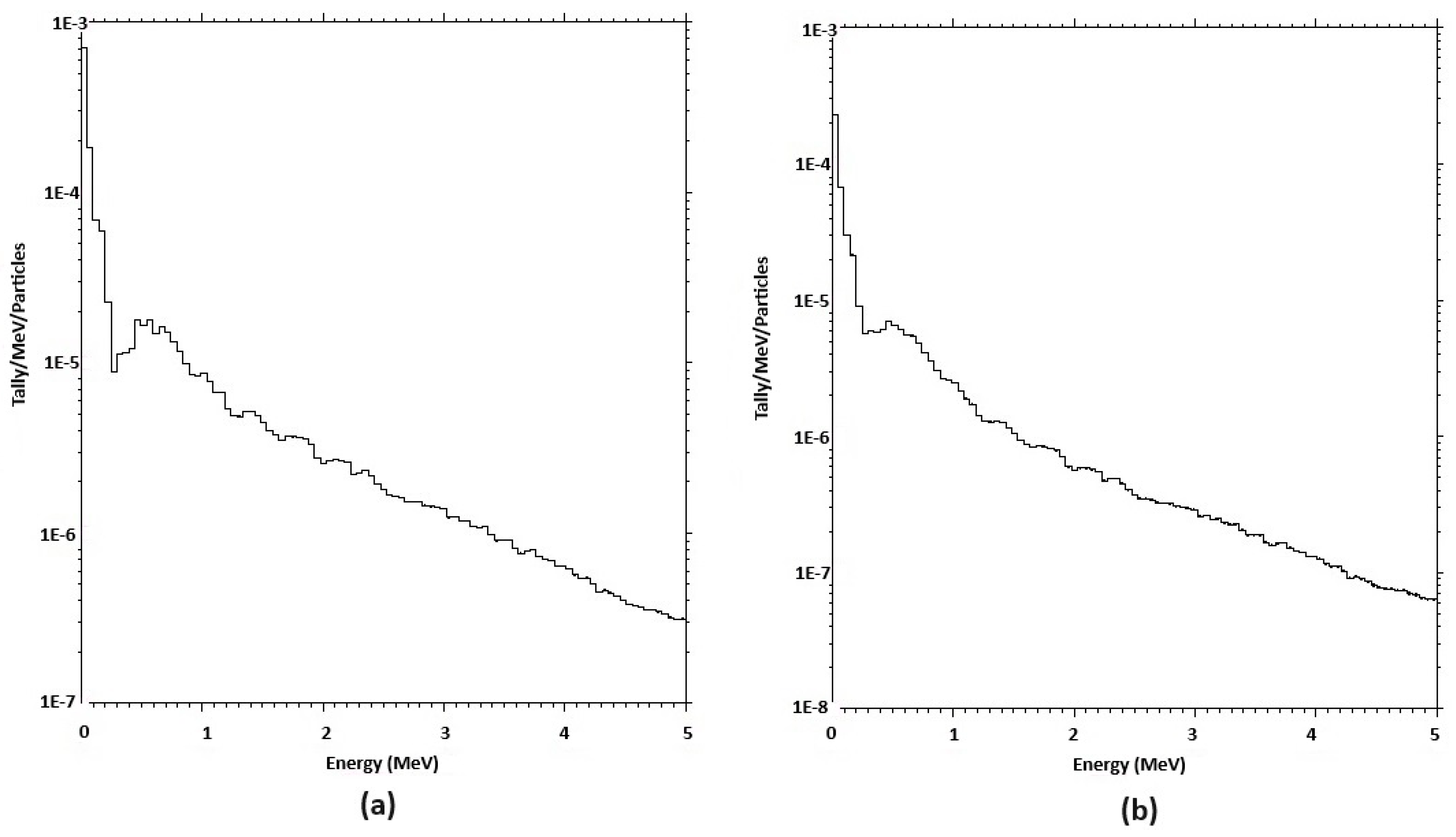
Figure 2 shows the 100 group neutron-energy spectra of the iMAGINE and EVOL reactor cores on the vessel coordination extracted from the IMAGINE-3BIC database (see Figure 1). A volumetric average flux-energy spectrum was applied in this case. It can be seen that the neutron-energy flux of iMAGINE is more intense than the EVOL one at the reactor vessel location, while the latter appears more intense in the reactor core location (see Figures 6 and 8 in [54] for greater resolution). These profiles serve as the starting point of radiation damage module processing, as they are employed directly in SPECTER and SPECTRA-PKA for damage and PKA calculations.
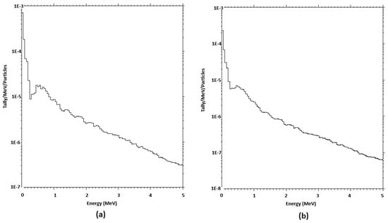
Figure 2.
Volumetric Average Neutron-Energy Spectra in vessel coordinates: (a) iMAGINE. (b) EVOL.
Two different materials were considered as reactor vessels: the iMAGINE project employs stainless steel, while Ni-based alloy has been proposed as the reactor vessel material in the EVOL project. Table 1 lists the composition of each material.

Table 1.
Composition of vessel materials, Stainless Steel (iMAGINE) and Ni Alloy (EVOL)-mass fraction.
3.1. PKA Results
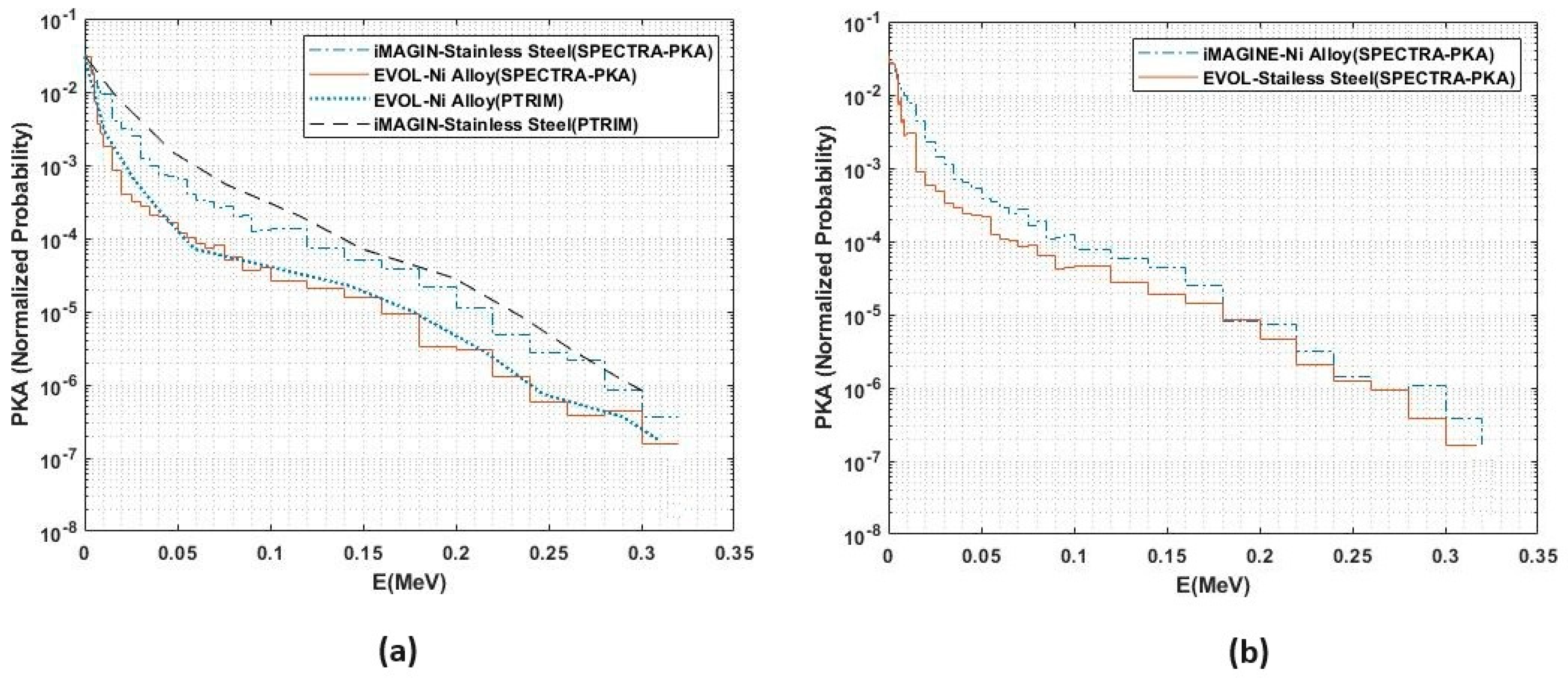
Primary knock-on atoms make the preliminary kernel of secondary and subsequent atomic cascades and the final induced damage in the material lattice. To calculate the PKA, SPECTRA-PKA read nuclear data and collapse the data for each reaction channel in a file with a user-defined energy spectrum of incident particles. SPECTRA-PKA outputs the resulting PKA spectra for each reaction channel read-in, as well as the summed PKA distributions for each different recoiling nuclide or element, including both the typically heavy residuals and the secondary-emitted light gas particles [64]. As discussed before, the developed “PTRIM” interface processes the exact data of the PTRAC card of the MCNPX and compiles particle movement data to find the PKA. The PKA results are shown in Figure 3. Figure 3a depicts the calculated PKA for the designated vessel materials of iMAGINE and EVOL using the SPECTRA-PKA and PTRIM interface. As can be seen in this figure, and as would be expected from the harder neutron-energy flux spectrum of iMAGINE in Figure 2, the PKA of the iMAGINE reactor vessel demonstrates higher energy than EVOL one, which can be interpreted as “more radiation-induced damage”. The results of PKA calculated by PTRIM are in agreement with those of SPECTRA-PKA, which confirms the reliability of the PTRIM interface calculation.
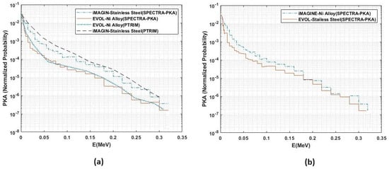
Figure 3.
PKA spectra of iMAGINE and EVOL reactor vessels.
Figure 3b examines the swapping of vessel materials between iMAGINE and EVOL, where iMAGINE and EVOL use Ni Alloy and Stainless Steel, respectively. As would be expected, iMAGINE still shows a higher energy PKA spectrum, although in comparison to Figure 3a, the profiles are in proximity with each other, which means a lower-energy PKA spectrum for iMAGINE. This figure can serve as a basic guide when selecting appropriate material for the iMAGINE vessel, as Ni alloy showed more radiation damage resistance, although final selection needs a comprehensive evaluation of various design parameters, such as thermal neutron radiation damage and corrosion mechanisms [65].
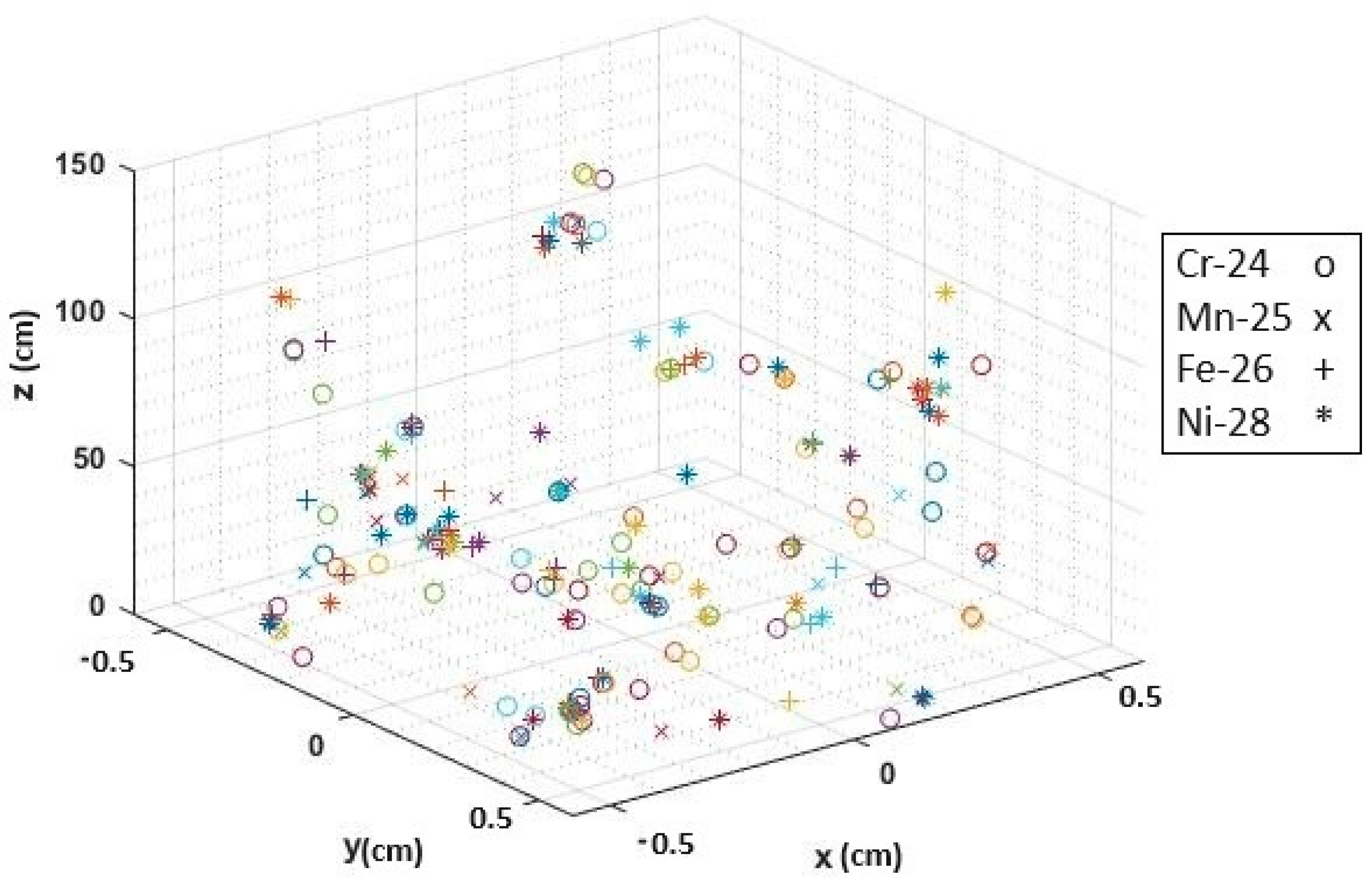
Figure 4 and Figure 5 show the PKA distribution of the iMAGINE and EVOL reactor vessels based on the atomic material number (MAT No), normalized per neutron tracking, for a element. This feature was added to this recent version of the PTRIM interface [25] and cannot be found in SPECTRA-PKA and SRIM. These figures are the easiest way to follow the radiation damage mechanism and the fraction of each atom within the composition of the reactor vessel. As can be found in Figure 4 and Figure 5, Cr-24 has the maximum portion of knock-on atoms among the vessel material compositions (see Table 2), while Mn-25 and Ni-28 exhibit lower knock-on populations. The displacement threshold energy (Ed) database shows a higher Ed = 40 eV for Mn and Ni in comparison to chromium (Ed = 25 eV) which means that chromium atoms can be displaced from their lattice with lower energy than manganese and nickel (although displacement energy is a complicated function of some different parameters, such as composition, and more investigation is required). Similarly, Figure 4 and Figure 5 confirm the effect of the higher energy neutron spectrum to produce more primary knock-on atoms in iMAGINE in comparison to EVOL (Figure 2 and Figure 3a); this can be interpreted as one of the main causes of the higher radiation damage in the iMAGINE reactor vessel.
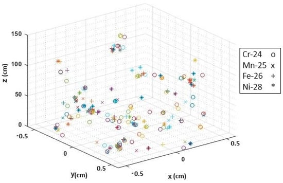
Figure 4.
PKA distribution of the iMAGINE vessel element based on atomic MAT No. (No more PKA can be seen higher than 60 cm).
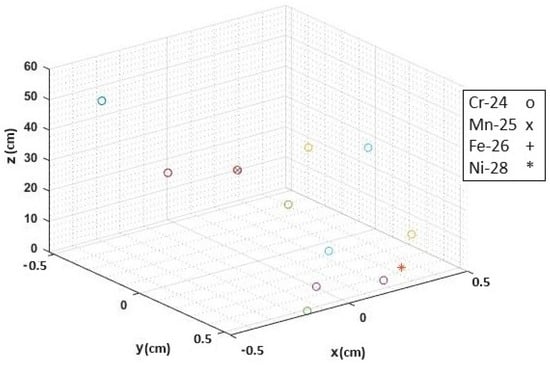
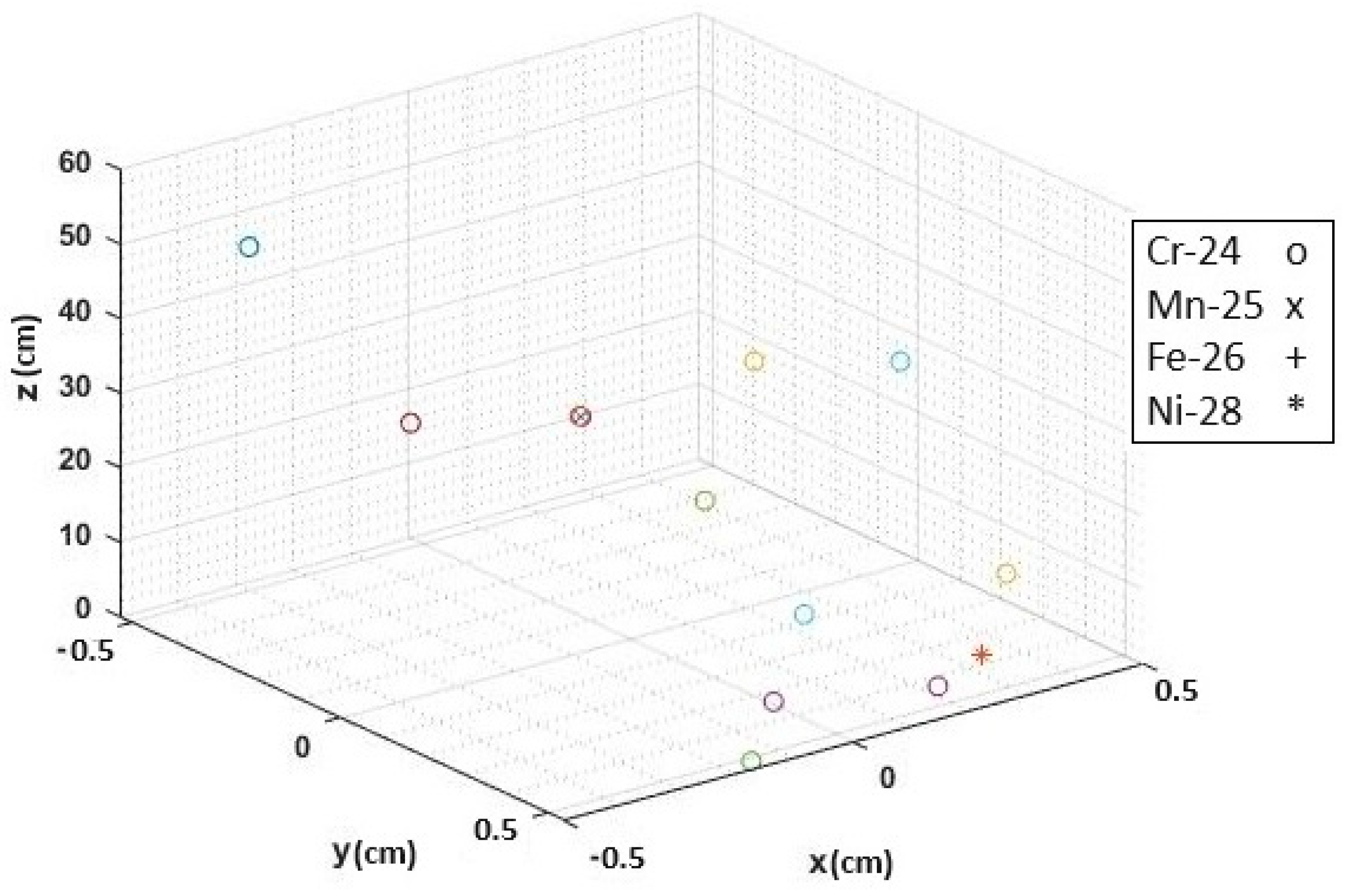
Figure 5.
PKA distribution of the EVOL vessel based on atomic MAT No.
Table 2.
Average PKA energies and dpa for iMAGINE and EVOL reactor vessels.
3.2. SRIM-2013 and Radiation Damage (dpa) Results
TRIM [47] is a group of programs which calculate the stopping and range of ions (10 eV − 2 GeV/amu) into matter using a quantum mechanical treatment of ion–atom collisions. This calculation is made very efficient by the use of statistical algorithms which allow the ion to make jumps between the calculated collisions and then average the collision results over the intervening gap. During the collisions, the ion and atom have a screened Coulomb collision, including exchange and correlation interactions between the overlapping electron shells. TRIM is part of the SRIM package [47].
PTRIM interface (Figure 1) compiles the SPECTRA-PKA and PTRAC PKA spectra in an input file that can be read by TRIM to start the radiation damage calculation based on binary collision approximation. The probabilistic origin of this calculation and resultant normalized 3D contour of damages are independent of the number of PKA particles, although an optimum number of PKA particles needs to be fed for calculations. The starting location of PKA particles can also affect the shape of the damage contour but not the values of radiation damage (as it is a statistical parameter). TRIM normally uses (0,0,0) as the starting coordinates of the ion. The starting position of the ion is always randomly modified within an atomic diameter so that successive ions starting, for example, at (0,0,0) will not have the same impact parameters as a target surface atom. Therefore, to achieve the best results, all the parameters of the particle were archived in the PTRIM interface (compiled using PTRAC card) and were employed to obtain the PKA particle location (x,y,z), cosine of moving angle (u,v,w), and kinetic energy of the particle (Ek) to prepare the TRIM input file. As the last step of input preparation, all locations have been set to (0,0,0), as advised by the TRIM manual. In addition, two methods of full cascade tracking and Kinchin-Pease (K-P) were applied in our simulation [47]. Figure 6, Figure 7, Figure 8 and Figure 9 show the total ionization and target displacement for iMAGINE and EVOL, simulated with the full cascade and Kinchin-Pease methods. Comparing the subfigures (a) and (b) for each individual figure demonstrates that a higher total ionization was calculated with the K-P method in comparison to the full cascade (F-C) one, as K-P only tracks the primary ion trajectories, whereas in the F-C method, target atom cascades are also allowed. Moreover, total displacement values calculated by the F-C method are less than the K-P ones, as can be seen in the figures, because “replacement collisions” were considered in the F-C method but were absent in K-P calculations (replacement collision is the process of filling vacancies in a lattice with PKAs).
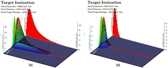
Figure 6.
SRIM-2013 Target Ionization on the iMAGINE reactor vessel: (a) Full-cascade (b) KP (red line shows penetration depth).
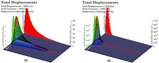
Figure 7.
SRIM-2013 Total Displacement on iMAGINE reactor vessel (a) Full-cascade (b) KP.
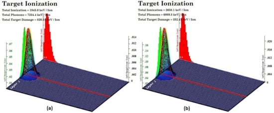
Figure 8.
SRIM-2013 Target Ionization on EVOL reactor vessel (a) Full-cascade (b) KP.
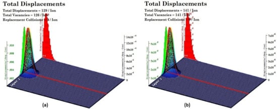
Figure 9.
SRIM-2013 Total Displacement on the EVOL reactor vessel: (a) Full-cascade (b) KP.
It should be noted that replacement collisions and thermal annealing are two main processes of reducing the number of vacancies in radiation-induced materials. The outcome of TRIM suffers two major limitations: (a) the build-up of ions or damage are disregarded (this means that TRIM tracks each ion in a bare material without considering the damage generated from the previous ones); (b) the temperature is set as 0 K, meaning that there are no thermal effects that either change the distribution of ions (thermal diffusion) or affect the target damage (thermal annealing). As we would expect, the values of total displacement for EVOL calculated with both the F-C and K-C methods were smaller than the iMAGINE ones, which confirms the correlation with the neutron-energy spectrum (Figure 2) and PKA spectra (Figure 3, Figure 4 and Figure 5) to predict higher values of radiation-induced damage to the iMAGINE stainless steel reactor vessel in comparison to the EVOL Ni alloy one. Moreover, the overall penetration of radiation damage (energetic PKAs) is deeper into the material in iMAGINE compared to EVOL, as can be found in Figure 7a and Figure 9a, and the maximum of damage appears at a slightly higher depth.
Finally, values of radiation damage based on displacement per atom (dpa) and average PKA energy using SPECTER, SPECTRA-PKA, and PTRAC + SRIM2013 are listed in Table 2, where the two first codes employ NRT-dpa for their calculation while the latter (PTRAC + SRIM2013) applies binary collision approximations for dpa calculations. These values were reported for a 100-year reactor lifetime with 3000 MWth power and a fluence of 1.5607 × 10²³ to show the amount of radiation damage in the long term.
Based on the previous trends in PKA spectra (Section 3.1), Table 2 shows higher values of radiation damage based on dpa for iMAGINE compared to EVOL for all three methods of calculation. The values of dpa calculated by PTRIM + SRIM2013 based on binary collision approximations were almost two times those calculated by SPECTER and SPECTRA-PKA (NRT-dpa), which originates from fundamental differences in their calculation methods. It needs to be considered that neither SPECTER and SPECTRA-PKA nor SRIM2013 consider thermal annealing in their calculations; this phenomenon can reduce the dpa values by 60%, depending on the operational temperature of the reactor pressure vessel.
4. Conclusions
Recent findings confirm that radiation-induced damage in nuclear structural materials can change their thermo-physical and micromechanical properties and, in worst-case scenarios, lead to the disintegration of those structures. These phenomena could be escalated in GenIV nuclear reactors where, in many concepts, the fast neutron spectrum is dominant. In this manuscript, a comprehensive radiation damage study was conducted on molten salt fast reactors (MSFRs) as one of the promising technologies of the fourth generation of reactors. To achieve this goal, a radiation damage module was added to the iMAGINE-3BIC package to make it capable of calculating the radiation-induced damage in different time periods of the reactors’ lifetime. Following the procedure from previously published parts of this series, i.e., Part 1 and 2, a comparative study was conducted based on iMAGINE (chloride based) and EVOL (fluoride based) molten salt reactors with stainless steel and Ni alloy as reactor vessel materials, respectively. As the results show (i.e., of the neutron-energy spectrum, PKA spectra and dpa that were calculated based on three different procedures), the radiation damage values expected in the iMAGINE reactor vessel were higher than in the EVOL one. The main reasons for this may be related to the harder neutron-energy spectrum of the iMAGINE core and the lower displacement energy of chromium (25 eV) in comparison to nickel (40 eV), which make up the major fractions of the iMAGINE and EVOL vessel compositions, respectively. Similar to this trend, Table 3 shows the comparative parameters of both reactors for a better understanding of the differences and to have an overall picture of radiation damage in MSFRs.
Table 3.
Comparison of radiation-induced damage on the iMAGINE and EVOL reactor core vessels.
Author Contributions
Conceptualization, O.N.-k. and B.M.; Methodology, O.N.-k.; Software, O.N.-k.; Validation, O.N.-k. and L.J.; Formal analysis, O.N.-k., L.J. and B.M.; Investigation, O.N.-k., L.J. and B.M.; Resources, O.N.-k. and B.M.; Data curation, O.N.-k.; Writing—original draft, O.N.-k.; Writing—review & editing, O.N.-k., L.J. and B.M.; Visualization, O.N.-k.; Supervision, B.M.; Project administration, B.M.; Funding acquisition, B.M. All authors have read and agreed to the published version of the manuscript.
Funding
The authors would like to appreciate the generous support of the Engineering and Physical Sciences Research Council, EPSRC-UK (grant numbers: EP/V027239/1).
Data Availability Statement
The original contributions presented in the study are included in the article, further inquiries can be directed to the corresponding author.
Conflicts of Interest
The authors declare no conflict of interest.
References
- GenIV International Forum. Annual Report 2022. 2022. Available online: https://www.gen-4.org/gif/jcms/c_216241/gif-annual-report-2022 (accessed on 8 September 2024).
- GenIV International Forum. Safety Design Guidelines on Structures, Systems and Components for Generation IV Sodium-Cooled Fast Reactor Systems. 2024. Available online: https://www.gen-4.org/gif/jcms/c_219467/gif-safety-design-guidelines-on-structures-systems-and-components-for-generation-iv-sodium-cooled-fast-reactor-systems (accessed on 8 September 2024).
- Was, G.S. Fundementals of Radiation Materials Science; Springer: Cham, Switzerland, 2014; ISBN 9783540494713. [Google Scholar]
- Wilczopolska, M.; Suchorab, K.; Gawęda, M.; Frelek-Kozak, M.; Ciepielewski, P.; Brykała, M.; Chmurzyński, W.; Jóźwik, I. Evolution of Radiation-Induced Damage in Nuclear Graphite–A Comparative Structural and Microstructural Study. Diam. Relat. Mater. 2024, 146, 111247. [Google Scholar] [CrossRef]
- Gentils, A.; Cabet, C. Investigating Radiation Damage in Nuclear Energy Materials Using JANNuS Multiple Ion Beams. Nucl. Instrum. Methods Phys. Res. Sect. B Beam Interact. Mater. At. 2019, 447, 107–112. [Google Scholar] [CrossRef]
- Jung, Y.; Kim, G.; Ha, W.; Ahn, S. Experimental Estimation of Radiation Damage Induced by 10B(n, α)7Li Reactions in Al-B4C Neutron Absorber Discharged from Spent Nuclear Fuel Pool. J. Nucl. Mater. 2023, 587, 154728. [Google Scholar] [CrossRef]
- Wang, M.; Zhang, D.; Richardson, P.; Wang, Z.; Jia, Y.; Tu, H.; Shi, L. Synthesis and Radiation Damage Tolerance of Mo 0.75 W 0.25 AlB Solid Solution for Nuclear Fusion Reactor Applications. Radiat. Phys. Chem. 2024, 223, 112025. [Google Scholar] [CrossRef]
- Kucal, E.; Czerski, K.; Kozioł, Z. Molecular Dynamics Simulations of Primary Radiation Damage in Silicon Carbide. Acta Phys. Pol. A 2022, 142, 747–752. [Google Scholar] [CrossRef]
- Stoller, R.E. Atomic-Scale Simulation of Radiation Damage in Structural Materials. In Proceedings of the NESLS Summer Seminar Series, USA, 5 July 2007. [Google Scholar]
- Kalaydjiev, K.; Baychev, M.; Popov, C. Temperature Waves in YBa 2 Cu 3 O 7-δ. J. Phys. Stud. 1998, 2, 250–254. [Google Scholar] [CrossRef]
- Lin, D.-Y.; Song, H.; Hui, X.D. Molecular Dynamics Simulation of Threshold Displacement Energy and Primary Damage State in Niobium. arXiv 2017, arXiv:1702.03598. [Google Scholar]
- Stoller, R.E.; Greenwood, L.R. An Evaluation of Neutron Energy Spectrum Effects in Iron Based on Molecular Dynamics Displacement Cascade Simulations. In Proceedings of the 19th International Symposium on the Effects of Radiation on Materials, Seattle, WA, USA, 16–18 June 2000. [Google Scholar]
- Gao, F. Modeling and Simulation of Primary Damage and Structure Evolution in Ceramics and Metals. In Proceedings of the 2nd Int. Workshop Irradiation of Nuclear Materials: Flux and Dose Effects, Cadarache, France, 4–6 November 2015; CEA: Cadarache, France, 2016. [Google Scholar]
- Verkhovtsev, A.V.; Solov’yov, I.A.; Solov’yov, A.V. Irradiation-Driven Molecular Dynamics: A Review. Eur. Phys. J. D 2021, 75, 213. [Google Scholar] [CrossRef]
- Tikhonchev, M.; Svetukhin, V.; Kapustin, P. Primary Radiation Damage of Zr-0.5%Nb Binary Alloy: Atomistic Simulation by Molecular Dynamics Method. Model. Simul. Mater. Sci. Eng. 2017, 25, 065017. [Google Scholar] [CrossRef]
- Guo, W. Molecular Dynamics Simulation of Irradiation Damage in Multicomponent Alloys. Ph.D Thesis, University of Tenessee, Knoxville, TN, USA, 2016. [Google Scholar] [CrossRef]
- Huang, H.; Tang, X.; Chen, F.; Liu, J.; Li, H.; Chen, D. Graphene Damage Effects on Radiation-Resistance and Configuration of Copper–Graphene Nanocomposite under Irradiation: A Molecular Dynamics Study. Sci. Rep. 2016, 6, 39391. [Google Scholar] [CrossRef]
- Buchan, J.T.; Robinson, M.; Christie, H.J.; Roach, D.L.; Ross, D.K.; Marks, N.A. Molecular Dynamics Simulation of Radiation Damage Cascades in Diamond. J. Appl. Phys. 2015, 117, 245901. [Google Scholar] [CrossRef]
- Stoller, R.E. Computational Theory and Modeling Relevant to Fusion Reactor Materials. In Proceedings of the ICFRM-17 Tutorial Session: Fusion Reactor Materials, Aachen, Germany, 11–16 October 2015. [Google Scholar]
- Daraszewicz, S. The Modelling of Electronic Effects in Molecular Dynamics Simulations. Ph.D. Thesis, University College London, London, UK, 2014; 172p. [Google Scholar]
- Trachenko, K.; Zarkadoula, E.; Todorov, I.T.; Dove, M.T.; Dunstan, D.J.; Nordlund, K. Modeling High-Energy Radiation Damage in Nuclear and Fusion Applications. Nucl. Instrum. Methods Phys. Res. Sect. B Beam Interact. Mater. At. 2012, 277, 6–13. [Google Scholar] [CrossRef]
- Lovecký, M.; Závorka, J.; Jiřičková, J.; Škoda, R. Radiation Damage Analysis of the First Generation VVER Spent Nuclear Fuel Casks. Ann. Nucl. Energy 2024, 196, 110214. [Google Scholar] [CrossRef]
- Yin, W.; Zu, T.; Cao, L.; Wu, H. Remarks and Improvements on Neutron KERMA Factors and Radiation Damage Cross Sections Calculated by NECP-Atlas and NJOY21 Using Different Evaluated Nuclear Data Libraries. Ann. Nucl. Energy 2021, 164, 108624. [Google Scholar] [CrossRef]
- Yin, W.; Zu, T.; Cao, L.; Wu, H. Development and Verification of Heat Production and Radiation Damage Energy Production Cross Section Module in the Nuclear Data Processing Code NECP-Atlas. Ann. Nucl. Energy 2020, 144, 107544. [Google Scholar] [CrossRef]
- Noori-kalkhoran, O.; Gei, M. Evaluation of Neutron Radiation Damage in Zircaloy Fuel Clad of Nuclear Power Plants: A Study Based on PKA and Dpa Calculations. Prog. Nucl. Energy 2020, 118, 103079. [Google Scholar] [CrossRef]
- Saha, U.; Devan, K.; Ganesan, S. Propagation of Uncertainties in Basic Nuclear Reaction Data to Uncertainties in the Parameters of Primary Radiation Damage by Neutrons. J. Nucl. Mater. 2018, 510, 43–60. [Google Scholar] [CrossRef]
- Ghazi Ardekani, S.F.; Hadad, K. Evaluation of Radiation Damage in Belt-Line Region of VVER-1000 Nuclear Reactor Pressure Vessel. Prog. Nucl. Energy 2017, 99, 96–102. [Google Scholar] [CrossRef]
- Kurudirek, M. Effective Atomic Number, Energy Loss and Radiation Damage Studies in Some Materials Commonly Used in Nuclear Applications for Heavy Charged Particles Such as H, C, Mg, Fe, Te, Pb and U. Radiat. Phys. Chem. 2016, 122, 15–23. [Google Scholar] [CrossRef]
- Lengar, I.; Čufar, A.; Conroy, S.; Batistoni, P.; Popovichev, S.; Snoj, L.; Syme, B.; Vila, R.; Stankunas, G. Radiation Damage and Nuclear Heating Studies in Selected Functional Materials during the JET DT Campaign. Fusion Eng. Des. 2016, 109–111, 1011–1015. [Google Scholar] [CrossRef]
- Kirk, M.A.; Li, M.; Xu, D.; Wirth, B.D. Predicting Neutron Damage Using TEM with in Situ Ion Irradiation and Computer Modeling. J. Nucl. Mater. 2018, 498, 199–212. [Google Scholar] [CrossRef]
- Noorikalkhoran, O.; Sevostianov, I. Micromechanical Modeling of Neutron Irradiation Induced Changes in Yield Stress and Electrical Conductivity of Zircaloy. Int. J. Eng. Sci. 2017, 120, 119–128. [Google Scholar] [CrossRef]
- Kirk, T.L. A Review of Scanning Electron Microscopy in Near Field Emission Mode, 1st ed.; Elsevier Inc.: Amsterdam, The Netherlands, 2017; Volume 204. [Google Scholar]
- Song, Z.; Xie, Z.H. A Literature Review of in Situ Transmission Electron Microscopy Technique in Corrosion Studies. Micron 2018, 112, 69–83. [Google Scholar] [CrossRef] [PubMed]
- Frenkel, D.; Smit, B. Chapter 4-Molecular Dynamics Simulations. In Understanding Molecular Simulation, 3rd ed.; Elsevier Inc.: Amsterdam, The Netherlands, 2023; pp. 97–124. [Google Scholar]
- GROMACS Development Team. GROMACS 2024.1 Documentation; GROMACS: Groningen, The Netherlands, 2024; pp. 1–877. [Google Scholar]
- Bernardi, R.; Bhandarkar, M.; Bhatele, A.; Bohm, E.; Brunner, R.; Buch, R.; Buelens, F.; Chen, H.; Chipot, C.; Dalke, A.; et al. NAMD User’s Guide NAMD Molecular Dynamics Software Non-Exclusive, Non-Commercial Use License; University of Illinois Urbana–Champaign: Urbana–Champaign, IL, USA, 2022. [Google Scholar]
- Sandia National Laboratories. LAMMPS Users Manual; Sandia National Laboratories: Albuquerque, NM, USA, 2014; Volume 209. [Google Scholar]
- Case, D.A.; Berryman, J.T.; Betz, Q.; Cai, D.S.; Cerutti, T.E.; Cheatham, T.A., III; Darden, R.E.; Duke, H.; Gohlke, A.W.; Goetz, S.; et al. The Amber Molecular Dynamics Package. Amber 2014. Available online: https://ambermd.org/doc12/Amber14.pdf (accessed on 8 September 2024).
- Carlson, J.; Gandolfi, S.; Pederiva, F.; Pieper, S.C.; Schiavilla, R.; Schmidt, K.E.; Wiringa, R.B. Quantum Monte Carlo Methods for Nuclear Physics. Rev. Mod. Phys. 2015, 87, 1067–1118. [Google Scholar] [CrossRef]
- Pelowitz, D.B.; Goorley, J.T.; James, M.R.; Booth, T.E.; Brown, F.B.; Bull, J.S.; Cox, L.J.; Durkee, J.W.; Elson, J.S.; Fensin, M.L.; et al. MCNP6 User’s Manual; Los Alamos National Laboratory: Los Alamos, NM, USA, 2013. [Google Scholar]
- Pelowitz, D.B. MCNPX User Manual Version 2.7.0; Los Alamos National Laboratory: Los Alamos, NM, USA, 2011. [Google Scholar]
- Romano, P.K.; Horelik, N.E.; Herman, B.R.; Nelson, A.G.; Forget, B.; Smith, K. OpenMC: A State-of-the-Art Monte Carlo Code for Research and Development. Ann. Nucl. Energy 2015, 82, 90–97. [Google Scholar] [CrossRef]
- Leppänen, J. Serpent–A Continuous-Energy Monte Carlo Reactor Physics Burnup Calculation Code; VTT Technical Research: Espoo, Finland, 2019. [Google Scholar]
- Ziegler, J.F.; Ziegler, M.D.; Biersack, J.P. SRIM–The Stopping and Range of Ions in Matter (2010). Nucl. Instrum. Methods Phys. Res. Sect. B Beam Interact. Mater. At. 2010, 268, 1818–1823. [Google Scholar] [CrossRef]
- Gilbert, M.R.; Sublet, J.-C. Differential Dpa Calculations with SPECTRA-PKA. J. Nucl. Mater. 2018, 504, 101–108. [Google Scholar] [CrossRef]
- Bailey, G.; Foster, D.; Kanth, P.; Gilbert, M. The F ISPACT-II User Manual; UK Atomic Energy Authority: Abingdon, UK, 2021. [Google Scholar]
- Ziegler, J.F. SRIM-2003. Nucl. Instrum. Methods Phys. Res. Sect. B Beam Interact. Mater. At. 2004, 219–220, 1027–1036. [Google Scholar] [CrossRef]
- Norgett, M.J.; Robinson, M.T.; Torrens, I.M. A Proposed Method of Calculating Displacement Dose Rates. Nucl. Eng. Des. 1975, 33, 50–54. [Google Scholar] [CrossRef]
- Zu, T.; Xu, J.; Tang, Y.; Bi, H.; Zhao, F.; Cao, L.; Wu, H. NECP-Atlas: A New Nuclear Data Processing Code. Ann. Nucl. Energy 2019, 123, 153–161. [Google Scholar] [CrossRef]
- Conlin, J.L. NJOY Documentation. 2021. Available online: https://docs.njoy21.io/ (accessed on 8 September 2024).
- Noori-kalkhoran, O.; Jain, L.; Powell, L.; Jones, A.; Aflyatunova, D.; Merk, B. On the Employment of a Chloride or Floride Salt Fuel System in Advanced Molten Salt Reactors, Part 2; Core Inventory, Fuel Burnup, and Salt Clean-Up System. Energies 2024, 17, 1475. [Google Scholar] [CrossRef]
- Merk, B.; Noori-kalkhoran, O.; Jain, L.; Aflyatunova, D.; Jones, A.; Powell, L.; Detkina, A.; Drury, M.; Litskevich, D.; Viebach, M.; et al. A Draft Design of a Zero-Power Experiment for Molten Salt Fast Reactor Studies. Energies 2024, 17, 2678. [Google Scholar] [CrossRef]
- Centre National de la Recherche Scientifique (CNRS). Evaluation and Viability of Liquid Fuel Fast Reactor System-EVOL (Project N°249696) Final Report. In Seventh Framework Programme of the European Community for Research and Technological Development and Demonstration Activities (2007–2013); CORDIS-EU: Brussels, Belguim, 2015. [Google Scholar]
- Noori-kalkhoran, O.; Litskevich, D.; Detkina, A.; Jain, L.; Cartland-Glover, G.; Merk, B. On the Employment of a Chloride or Fluoride Salt Fuel System in Advanced Molten Salt Reactors, Part 1: Thermophysical Properties and Core Criticality. Energies 2022, 15, 8865. [Google Scholar] [CrossRef]
- Robinson, M.T.; Torrens, I.M. Computer Simulation of Atomic-Displacement Cascades in Solids in the Binary-Collision Approximation. Phys. Rev. B 1974, 8, 15. [Google Scholar] [CrossRef]
- Kinchin, G.H.; Pease, R.S. The Displacement of Atoms in Solids during Irradiation. Solid State Phys. 1956, 2, 307. [Google Scholar]
- Nelson, R.S. Improved Calculations on the Number of Displacements Produced In Iron During Fast Neutron Irradiation; Atomic Energy Research Establishment: Harwell, UK, 1969. [Google Scholar]
- Corbett, J.W.; Ianniello, L.C. Radiation-Induced Voids in Metals. In Proceedings of the 1971 International Conference, Albany, NY, USA, 9–11 June 1971; Atomic Energy Commission (AEC): Washington, DC, USA, 1972. [Google Scholar]
- Beeler, J.R. Displacement Spikes in Cubic Metals. I. Alpha-Iron, Copper, and Tungsten. Phys. Rev. 1966, 150, 470–487. [Google Scholar] [CrossRef]
- Gibson, J.B.; Goland, A.N.; Milgram, M.; Vineyard, G.H. Dynamics of Radiation Damage. Phys. Rev. 1960, 120, 1229–1253. [Google Scholar] [CrossRef]
- Greenwood, L.R. SPECOMP Calculations of Radiation Damage in Compounds; Argonne National Laboratory: Argonne, IL, USA, 1989. [Google Scholar]
- Greenwood, L.R.; Smither, R.K. SPECTER: Neutron Damage Calculations for Materials Irradiation; Argonne National Laboratory: Argonne, IL, USA, 1985. [Google Scholar]
- Sublet, J.-C.; Eastwood, J.W.; Morgan, J.G.; Gilbert, M.R.; Fleming, M.; Arter, W. FISPACT-II: An Advanced Simulation System for Activation, Transmutation and Material Modelling. Nucl. Data Sheets 2017, 139, 77–137. [Google Scholar] [CrossRef]
- SPECTRA-PKA Documentation. 2021. Available online: https://github.com/fispact/SPECTRA-PKA (accessed on 2 July 2024).
- Merk, B.; Konheiser, J. Neutron shielding studies on an advanced molten salt fast reactor design. Ann. Nucl. Energy 2014, 64, 441–448. [Google Scholar] [CrossRef]


Disclaimer/Publisher’s Note: The statements, opinions and data contained in all publications are solely those of the individual author(s) and contributor(s) and not of MDPI and/or the editor(s). MDPI and/or the editor(s) disclaim responsibility for any injury to people or property resulting from any ideas, methods, instructions or products referred to in the content. |
© 2024 by the authors. Licensee MDPI, Basel, Switzerland. This article is an open access article distributed under the terms and conditions of the Creative Commons Attribution (CC BY) license (https://creativecommons.org/licenses/by/4.0/).