Article

A Novel PI-Based Control Structure with Additional Feedback from Torsional Torque and Its Derivative for Damping Torsional Vibrations

by
Piotr Derugo
1,
Amanuel Haftu Kahsay
1,
Krzysztof Szabat
1,2,*,
Kosuke Shikata
2 and
Seiichiro Katsura
2
1
Faculty of Electrical Engineering, Wrocław University of Science and Technology, PL50370 Wrocław, Poland
2
Department of System Design Engineering, Keio University, Yokohama 223-8522, Japan
*
Author to whom correspondence should be addressed.
Energies 2024, 17(19), 4786; https://doi.org/10.3390/en17194786
Submission received: 31 May 2024 / Revised: 6 September 2024 / Accepted: 23 September 2024 / Published: 25 September 2024
(This article belongs to the Section F3: Power Electronics)

Abstract

:
This paper presents issues related to the damping of torsional vibrations in a system with elastic coupling. A novel PI-based control structure with additional feedback from torsional torque and its derivative is proposed. For the estimation of the required variables, the integral observer is proposed. Analytical expressions are presented to enable the selection of parameters of the control system. The relationship between the considered system and popular structures with a PI controller and one additional feedback from torsional torque and the derivative of torsional torque is pointed out. The proposed control structure is tested under simulation and experimental studies.

1. Introduction

The industry is placing increasingly stringent demands on new and upgraded process lines. For economic reasons, the aim is to increase productivity and raise the quality of manufactured products. This is undertaken by increasing the speed of actuators. However, simply increasing the speed/position is limited significantly by the physical properties of the used components [1,2,3,4]. Currently, electric motors are the most frequently used drives in modern industry. These are usually connected to the working machine by a mechanical coupling. Developments in microprocessor technology, power electronics, and control theory have led to the development of a number of methods for very fast (virtually non-inertial) forcing of driving torque. However, the increase in drive dynamics results in the finite stiffness of the mechanical connection. This, in turn, leads to the development of torsional vibrations. Torsional vibrations negatively affect the system in a number of ways. They can lead to the direct destruction of the mechanical shaft or the shortening of the lifecycle of the drive. Torsional vibrations reduce the accuracy of speed/position control and therefore have a negative effect on the quality of manufactured products. They can also be a source of noise [5,6,7,8,9].
Torsional vibrations are originally observed in high-power drives, such as machines used in the steel, textile, or paper industries. Other classic examples are drives for conveyor belts or radio telescopes. In recent years, the problem of torsional vibrations has been recognised in wind power plants, electric cars, or hybrid and electric aircrafts. It is also reported in low- and medium-power drives—e.g., servo drives, robot drives, traditional hard drives in computers, mechanical beams or MEMS [10,11,12,13,14,15,16,17,18].
The most effective methods designated to damp torsional vibrations are based on active control strategies. Different approaches can be distinguished here. A modification of classical structure is necessary since a system with a PI controller cannot damp torsional vibrations effectively [19,20,21]. One of the most popular solutions is a system with additional torsional torque feedback [21,22,23,24]. In this case, two approaches can be considered. The first, called Resonance Ratio Control, is based on changing the original resonant to anti-resonant frequency ratio. The torsional torque is treated as a disturbance variable and fed into the torque reference loop. By setting the appropriate Resonance Ratio, effective vibration damping is achieved. Due to the measurement noise, a low-pass filter is necessary. This introduces a delay and thus reduces the efficiency of the vibration damping. The second well-known approach is the use of a torsional torque derivative [21,22]. This allows effective vibration damping, but on the other hand, requires accurate information about this variable (estimation is difficult due to measurement noise).
Using a state controller is another example of the active methods. Since all variables are available to the control structure, it is possible to place the poles of the closed-loop system arbitrarily [25,26,27]. The problem that the system designer faces is the location of poles. In the case of a system with changeable parameters, it is possible to obtain robust responses from a plant by selecting certain pole positions. An alternative approach to the classical state controller is a structure based on the forced dynamic control law [28]. Like the classical state controller, it has feedback from all variables including load speed. However, it additionally uses information about the load moment and its derivatives. This makes it possible to eliminate the influence of the load moment on the speed of the working machine. The paper [28] shows a modification of the FDC control system by using two control loops, namely the torque and the speed of the load machine. This approach allows for the limiting of torsional torque and, consequently, reduces stresses in the mechanical shaft.
For a system with variable parameters, it is necessary to use one of the robust control methods. One of the most popular frameworks discussed in the literature is sliding control [29,30,31,32,33]. The operation of the system can be divided into two phases. In the reaching phase, the system is sensitive to external disturbances, while in the sliding phase, it is no longer so. A classic disadvantage of sliding control is the occurrence of chattering. It is usually eliminated by replacing the sgn function with its continuous approximation. However, this reduces the robustness of the designed structure. In [30], authors propose sliding control to regulate the load speed. The required variables are provided by a Luenberger observer. The obtained results demonstrate the robustness of the structure. In [31], a dual-layer network is used to estimate the changeable parameters of the plant, namely the time constant of the working machine and elasticity. The paper [32] proposes a system in which a state controller and a sliding controller are combined. The task of the sliding part is to compensate for non-linearities and changes in the parameters of the object. Good results are reported.
Another approach to controlling a two-mass system with variable parameters is the use of adaptive control [33,34,35,36,37]. There are a number of papers in the literature that describe such applications. As an example of indirect adaptive control, ref. [33] can be used. In [37], the application of a Kalman filter for the estimation of a changeable system parameter—the moment of inertia of a load machine—is described. Based on the estimated value, the controller settings are retuned. Yet, a different approach is direct adaptive control [33]. Based on the comparison of the system output with the desired value, the controller settings are changed.
In recent years, there has been a growing interest in model predictive control (MPC) in electric drive and power electronics [38,39,40,41,42,43,44,45]. This algorithm is based on an iterative solution. The optimal control signal is calculated using a model and the actual state of the plant for an assumed prediction horizon. An important advantage of predictive control is that the constraints of control signals and internal state variables can be directly taken into account. As a disadvantage, its high computational complexity can be mentioned. One of the first papers demonstrating the application of predictive control in a two-mass system is [39], presenting both simulations and experimental results. It compares properties of MPC and PI controller-based systems. The much better dynamic properties of the MPC structure are reported. It results from the possibility of changing the control signal from maximum to minimum in one sampling step. The papers [41,42,43] demonstrate the application of MPC control to a linear and non-linear two-mass system. The authors analyse the levels of torsional torque limitation and identify its optimum value. It prevents additional torsional torque oscillations during constrained operation (e.g., during start-up). In [45], an MPC control system is analysed, in which the electromagnetic part of the motor is also taken into account. The results were confirmed by bench tests with a PMSM motor.
As shown above, in the literature, there are several control methods designed for two-mass drive systems. Despite the existence of advanced control methods, some of the most widely used are still systems based on the linear control theory, especially the system with a PI controller and selected feedback. The structure with additional feedback from the torsional torque and speed of the working machine is particularly common. The information on all variables is also necessary for the realization of the state or FDC controller. Since in industrial systems usually only driving torque and speed signals are available, the remaining variables (torsional torque, load machine speed) must be estimated. In the literature, there are many methods for estimating state variables. One of the most common is a Luenberger observer or Kalman filter [46,47,48,49,50]. In their structure, the parameters of the drive system including the time constant of elasticity and the time constant of the working machine are used. Their change leads to oscillations in the state variables. For this reason, control structures that do not require information on the load machine speed and consequently implementation of the abovementioned observers are sought after. The main futures of the popular control structures for vibration damping are shown in Table 1.
The main goal of this paper is to propose a novel PI-based control structure with additional feedback from the torsional torque and its derivative. Additionally, an integral observer is also developed for the estimation of those variables. Compared to previously discussed approaches [46,47,48,49,50], these estimators do not include parameters related to the elastic shaft or the load machine. Thus, changes in their parameters do not affect the quality of the estimation of the required variables.
Control structures with a PI controller and one additional feedback from torsional torque or its derivative are known from the literature. To locate the proposed control structure adequately, the following points are also included in this paper:
-
an analysis of the control system with a PI controller and with one additional feedback from the torsional moment or the derivative of the torsional torque; presentation of mathematical equations allowing for the placing of the poles of the closed-loop system on a complex plane;
-
an analysis of a proposed control system with a PI controller and with two additional feedbacks from the torsional moment and its derivative; developing the analytical formulas for the location of the system closed-loop poles at a complex plane;
-
a critical comparative analysis of the three considered systems;
-
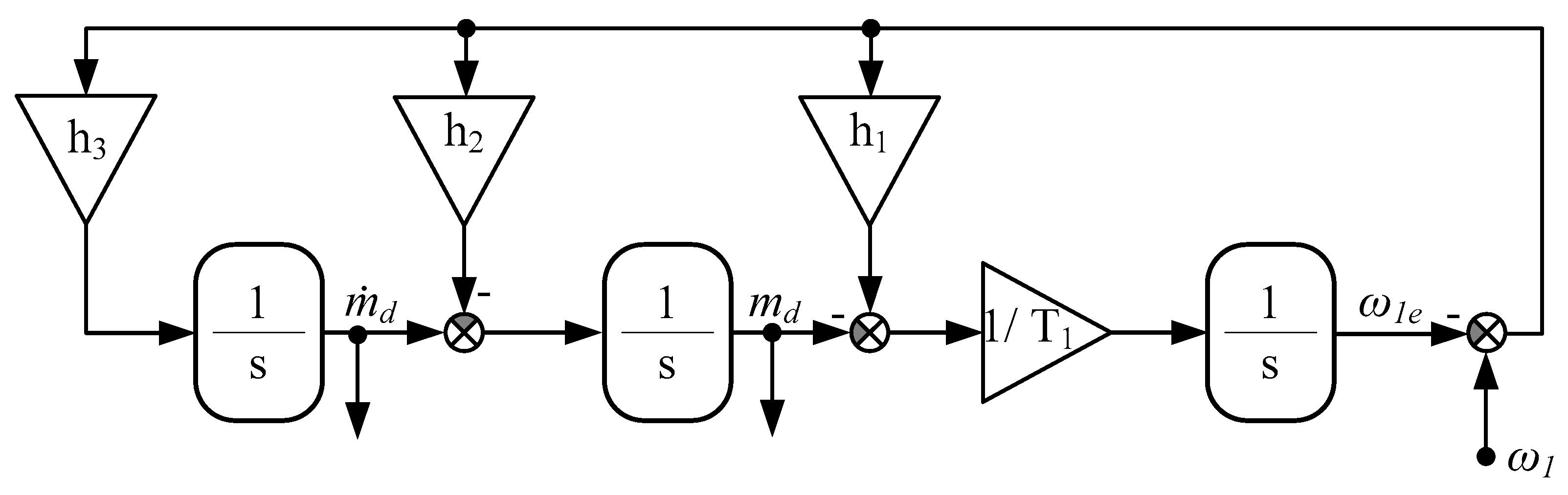
developing the integral observer for estimation of the torsional torque and its derivative; presentation of the analytical formulas allowing shifting poles of the observer in the desired location.
-
simulation and experimental verification of the proposed control structure.
This paper is divided into four chapters. After introducing the topic of torsional vibrations, a mathematical model of the two-mass system is presented. Then the PI-based control structures with one additional feedback are presented. Next, the proposed control system with two feedbacks from torsional torque and its derivative is described. A systematic analysis of the three systems is submitted. Also, the analytical formulas based on the poles-placement methodology are developed. Additionally, the design of the integral observer is demonstrated. In the next sections, simulations and experimental results are presented and discussed. The last chapter provides a summary of the findings.

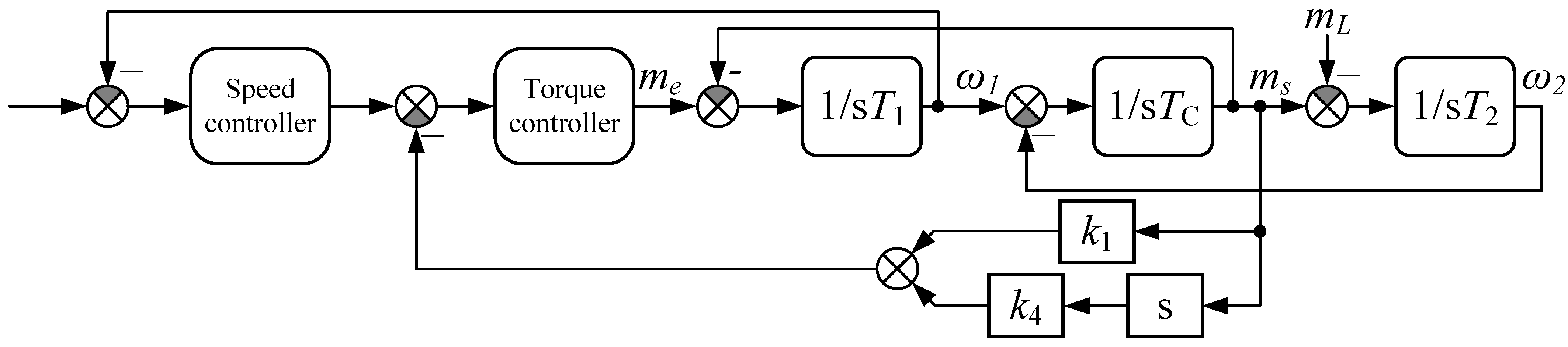
2. Mathematical Model of the Plant and Proposed Control Structures
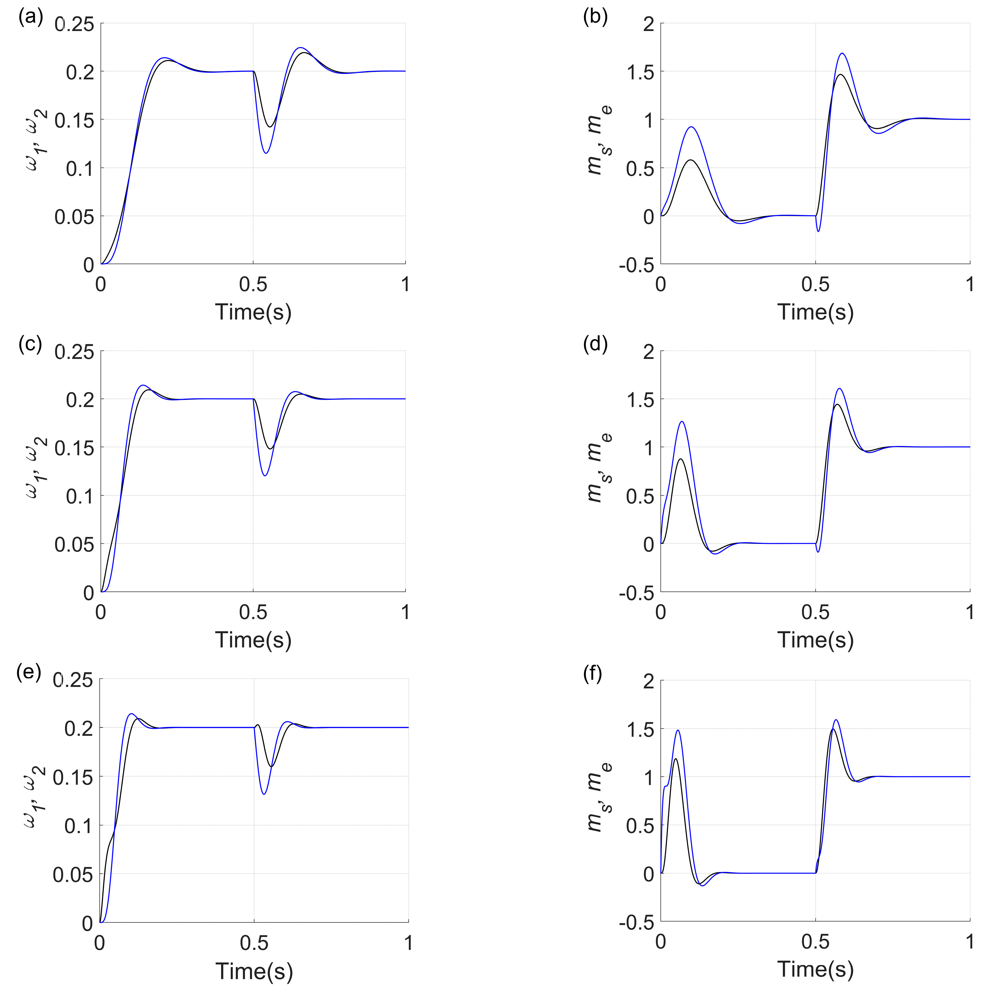
Many models in the literature can be used to analyse a drive system with an elastic connection. For instance, field models offer very high accuracy. However, their huge disadvantage is very high computational complexity. In recent years, papers describing the wave model have appeared. This is an interesting approach intended for systems with multiple masses and elastic elements. Still, due to the numerous degrees of freedom, analysing such a model is difficult. On the other hand, commonly used differential equations-based models offer a relatively simple solution. They allow for analysing and subsequently designing the control structure. One of the most popular models describing a two-mass drive is the inertial-free system. It consists of two basic masses—i.e., the first one represents the inertia of the drive motor, and the second mass is related to the load machine. Both masses are connected by a long (flexible) shaft. The state equation of the considered system is presented below.
d d t ω 1 ( t ) ω 2 ( t ) m s ( t ) = 0 0 1 T 1 0 0 1 T 2 1 T c 1 T c 0 ω 1 ( t ) ω 2 ( t ) m s ( t ) + 1 T 1 0 0 m e + 0 1 T 2 0 m L
where ω1 and ω2 are the speeds of motor and load side respectively, me, ms, and mL are the electromagnetic, torsional, and load torques, T1 and T2 are the mechanical time constant of the motor and load side, and Tc is the parameter that represents the elasticity of the coupling.
Figure 1 provides a diagram of the two-mass system.
The basic speed control structure of an electric drive is based on the cascade concept. It consists of two control loops. The internal loop includes the following elements: the electromagnetic part of the motor, the current (voltage) measurement system, the power electronic converter, and the torque controller. The purpose of this loop is to force the electromagnetic torque rapidly. In modern control methods, this torque is considered to be practically inertia-free. Hence, the dynamics of this loop are often neglected in the analysis of the outer speed control loop.
The basic speed controller used in the electric drive is the PI type controller. However, as shown in many papers, this approach is inefficient—i.e., this system is not able to damp torsional vibrations effectively. Since large oscillations may occur in the system’s transients, other approaches are needed.
The diagram of the proposed control system is shown in Figure 2. It consists of a two-mass system, a driving torque loop, a PI-type speed controller, additional feedback from the torsional torque (k1), and the torsional torque derivative (k4). The designation of additional couplings is [21].
In order to design the control structure, it is necessary to choose one of the methods available in the literature. In this paper, the poles placement method is applied. The main transfer function of the control system with additional feedback is presented below (2):
G ω 2 s = ω 2 s ω r s = G r s s 2 T 2 T c + 1 s 3 T 2 T c T 1 + s 2 T 2 T c G r s + s T 1 + T 2 1 + k 1 + s k 4 + G r s
The transmittance of the PI controller is described as follows (3):
G r s = K P + K I 1 s
where KI and KP are PI controller gains.
The characteristic equation of a system with a PI controller is submitted below (4):
p s = s 4 + s 3 T 2 T c K P + T 2 k 4 T 1 T 2 T c + s 2 T 2 T c K I + T 1 + T 2 + T 2 k 1 T 1 T 2 T c + s K P T 1 T 2 T c + K I T 1 T 2 T c
The design procedure of control structure is as follows. In the first step, the characteristic equation of the system is determined.
Because the system is of the fourth order, the desired polynomial has the following form:
s 2 + 2 ξ ω 0 s + ω 0 2   s 2 + 2 ξ ω 0 s + ω 0 2 = 0 ,
where ξ is the damping coefficient, and ω0 is the resonant frequency of the closed-loop system.
After multiplying the two factors, the final form is obtained (6):
s 4 + s 3 ( 4 ξ r ω r ) + s 2 2 ω r 2 + 4 ξ r 2 ω r 2 + s 4 ξ r ω r 3 + ω r 4 = 0
Then, the comparison of particular factors in (4) and (6) is undertaken. Setting k1 and k4 to zeros, the system without additional feedback is analysed. Formulas allowing for the setting of the controller gains are displayed in (7) and (8).
ξ P I = 1 2 T 2 T 1 , ω P I = 1 T 2 T c
K P = 2 T 1 T c , K I = T 1 T 2 T c
A controller without additional feedbacks cannot damp the torsional vibrations effectively. Large overshoots and [19,20,21] oscillations can occur in the speed and torque transients. They result from the fact that the system is of the fourth order and there are only two design parameters. Therefore, it is necessary to introduce additional feedback(s) into the system.
When one additional feedback is used, the designer has three coefficients available. This means that an arbitrary pole location is not possible. However, unlike in the previous case, the desired damping coefficient value can be obtained.
The resonance pulsation and damping coefficient of the poles for a system with additional feedback from the torsional torque k1 are described by (9).
ξ k 1 = 1 2 T 2 1 + k 1 T 1 , ω 0 k 1 = 1 T 2 T c
The control system coefficients are defined in (10).
k 1 = 4 ξ r 2 T 1 T 2 1 , K P k 1 = 2 T 1 1 + k 1 T c , K I k 1 = T 1 T 2 T c .
A system with additional coupling from the torsional torque derivative k4 is considered next. The resonant pulsation of the system and the damping ratio are defined in (11).
ξ k 4 = T c + x 4 T 1 T c T 1 + T 2 + T c 4 T c + x 1 2 , ω 0 k 4 = 1 T 2 T c + x
where x is the solution of the second order Equation (12).
x 1,2 = b ± b 2 4 a c 2 a
where
a = T 2 2 T 1 + T 2 ,   b = 2 T 2 3 T c 4 ξ r 2 T 1 T 2 2 T c , c = T 2 3 T c 2 4 ξ r 2 T 1 T 2 2 T c 2 .
The control system coefficients are represented as (14):
k 4 = x K p k 4 ,   K P k 4 = 4 ξ r ω 0 k 4 T 1 T c T c + x ,   K I k 4 = ω 0 k 4 4 T 1 T 2 T c .
The coefficients of the system with a PI controller and one additional feedback can be calculated using (10) and (14). A damping factor is used here as a design parameter. By setting an appropriate value, the effective damping of oscillations is achieved. It should be noted that the rise time does not depend on the system designer, yet it results from the resonant pulsation of the closed-loop poles.
A structure with two additional feedbacks from the torsional torque and its derivative is considered next. Here, the control system designer has four design coefficients. This means that the independent location of the poles on the complex plane is possible. Following the poles placing methodology, Equations (15)–(18) are obtained:
K P = 4 ξ ω 3 T 1 T 2 T c
K I = ω 4 T 1 T 2 T c
k 1 = 2 ω 2 + 4 ξ 2 ω 2 T 1 T c ω 4 T 1 T 2 T c 2 T 1 T 2 1
k 4 = 4 ξ ω T 1 T c 4 ξ ω 3 T 1 T 2 T c 2
In this paper, three control structures with PI controllers are analysed. The first has additional feedback from the torsional torque, the second from the derivative of the torsional torque, and the third has both of these feedbacks. It is important to find the relationships between these structures. Hence, the gains of the control system are determined according to (15)–(18) as a function of the variable resonant pulsation. The value of the damping ratio is constant here. The obtained characteristics are presented in Figure 3.
As can be seen from the characteristics presented in Figure 3, gains KI and KP of the PI controller increases accordingly to changes in the value of the resonant pulsation (Figure 3c,d). The situation is different for the gains in the additional feedback. The gain k1 has two zero points and the coefficient k4 has one. These points correspond to the equations derived for systems with one additional feedback. Thus, the considered control system with two additional feedbacks can be regarded as a generalization of those two systems.
To implement the control structure, it is necessary to have information about additional state variables present in the system, namely the torsional torque and the derivative of the torsional torque. These variables are usually unavailable for measurement. Therefore, it is necessary to use one of the available methods to calculate them.
In numerous papers, the torsional torque is treated as a disturbance torque denoted as md [22,23]. In this case, its determination is possible by using a system known as a disturbance observer. The classical disturbance observer in its direct and modified form is shown in Figure 4a,b.
The disturbance observer is based on the equation describing the dynamics of the driving motor. To determine the disturbance torque (which in this case is the torsional torque), it is necessary to differentiate the speed of the drive motor and compare the signal with the driving torque. The direct differentiation of the speed signal, however, leads to the amplification of measurement noise, which is a drawback of this solution. To minimize this effect, a low-pass filter is put into the system Figure 4a. However, it introduces a delay in the signal. In practice, the system presented in Figure 4b, in which the direct differential operation is abandoned, is used more frequently.
To determine the derivative of the disturbance torque, the obtained disturbance torque signal (Figure 5) must be differentiated. As before, this operation amplifies the measurement noise. To minimize it, a second low-pass filter is used.
For the elimination of the drawbacks of direct derivation evident in the above presented system, another solution is considered. This paper proposes integral observers to determine the torsional torque signal and its derivative. The block diagram of the considered system is presented in Figure 6.
Direct differentiation operations are not required in the integral observer. So, the measurement noises are not amplified in this system directly.
The characteristic equation of the system shown in Figure 6 is defined as in (19):
p ( s ) = s 3 + s 2 h 1 T 1 s h 2 T 1 h 3 T 1
In this case, the desired polynomial is (20):
p ( s ) = s 2 + 2 a p s + p 2 s + p
The observer’s correction factors have the following form (21)–(23):
h 1 = T 1 2 a p + p
h 2 = T 1 2 a p 2 + p 2
h 4 = T 1 p 3
The proposed integral observer has several advantages. Unlike classical disturbance observers, it is not based on signal derivatives. This means no amplification of measurement noise. Another advantage is the relatively simple design procedure and form of the estimator, which is important for practical applications. The next advantage of the estimator is the absence of shaft and load machine parameters in their structure. Their change or misidentification does not affect the accuracy of the estimation.

3. Simulation Study

This chapter presents the results of simulation studies. During the tests, all three analysed control systems are examined. The test scenario is as follows. At time t = 0 s, the drive system is started. The value of the reference speed is 0.2 of the nominal value. Subsequently, at time t = 0.5 s, the load torque is applied to the system. The presented simulation studies are performed in the Matlab-Simulink environment.
The structure with an additional feedback from the k1 torsional moment is tested first. The values of the control coefficients are determined according to (10). The damping factor is set to 0.7. The obtained transients are shown in Figure 7a,b. Then, the second considered system is tested. It is a structure with a PI controller and additional feedback from the derivative of torsional torque. In this case, there are two solutions with different dynamic properties. The values of the control system coefficients are selected according to (12)–(14), and the value of the damping coefficients is 0.7. The obtained transients are shown in Figure 7c–f.
Based on the analysis of the transients shown in Figure 7, the following conclusions can be drawn. Firstly, both tested systems operate correctly. There is a slight overshoot in the response of the system (the speed of the load machine) due to the set value of the damping factor (Figure 7a,c,e). The system with additional feedback from the derivative of torsional torque has two solutions. One of them provides a very dynamic response of the system. This is evident both in the speed waveforms of the motor—there are clear phases of acceleration, deceleration, and re-acceleration (Figure 7e)—as well as in the very dynamic forcing of the driving torque (Figure 7f). Its maximum value exceeds two. For the second possible setting, it is about 0.8 (Figure 7d). For the system with additional k1 feedback, the maximum value approaches the nominal value (Figure 7b).
Next, the system with a PI controller and with two additional feedbacks, k1 and k4, is tested. The test scenario is identical to previous cases. The value of the damping coefficient is assumed to be 0.7, while the following values of resonant pulsation are set: ω = 30, 45, and 60. The obtained transients are shown in Figure 8.
Figure 8 shows the transients of the speed of the drive motor and the load machine (Figure 8a,c,e) and the driving and torsional torque (Figure 8b,d,f). The system is first tested for the value ω = 30. In this case, the maximum value of the forced driving torque is about one, which is similar to that in Figure 7b. Changing the pulsation value to 45 leads to an increase in drive dynamics. This manifests itself in a speed reduction of the settling time as well as the forcing of a higher value of the driving torque (the maximum value already exceeds the nominal torque) as well as torsional torque. In the last tested system, the maximum torque value approaches 1.6 of the nominal torque, so it is twice as high as in Figure 8b. Also, the speed settling time shortens twice.
Next, the proposed integral observer for estimating torsional torque and its derivative is tested. The test scenario is as follows. The speed transients of the drive motor and the drive torque are recorded in the proposed control structure for ω = 45. The start-up of the system occurred at time t0 = 0 s. The load torque is applied to the system at time t1 = 0.3 s. Subsequently, Gaussian white noises are added to the speed signal. Both motor speed and drive torque signals are applied to the estimator. The values of the resonant pulsation are set to p = 300, 150, and 100. Figure 9 shows the transients of the estimated drive system variables and the estimation errors.
Based on the transients shown in Figure 9, the following conclusions can be drawn. If the resonant pulsation of the estimator is set too small (blue colour p = 100), there is no visible noise in the waveforms of the estimated variables. However, the large delay present in the estimation of these variables is unacceptable in the practical implementation of the system. The bigger the gains in the observer, the larger the noise levels in the estimated variables. This is especially evident in the transients in the system with p = 300 (green colour). The noise level exceeds the amplitude of the useful signal (Figure 9c,d). The observer with a gain of p = 150 has the most favourable properties. It determines the torque transient with a minimal delay and low noise level. Comparing the transients of the estimated torsional torque and the estimated derivative of torsional torque, a difference can be seen. The estimate of torsional torque has better quality. It results from the fact that its calculation is based on the error signal multiplied by the correction coefficient and signal of the estimated derivative of torque.

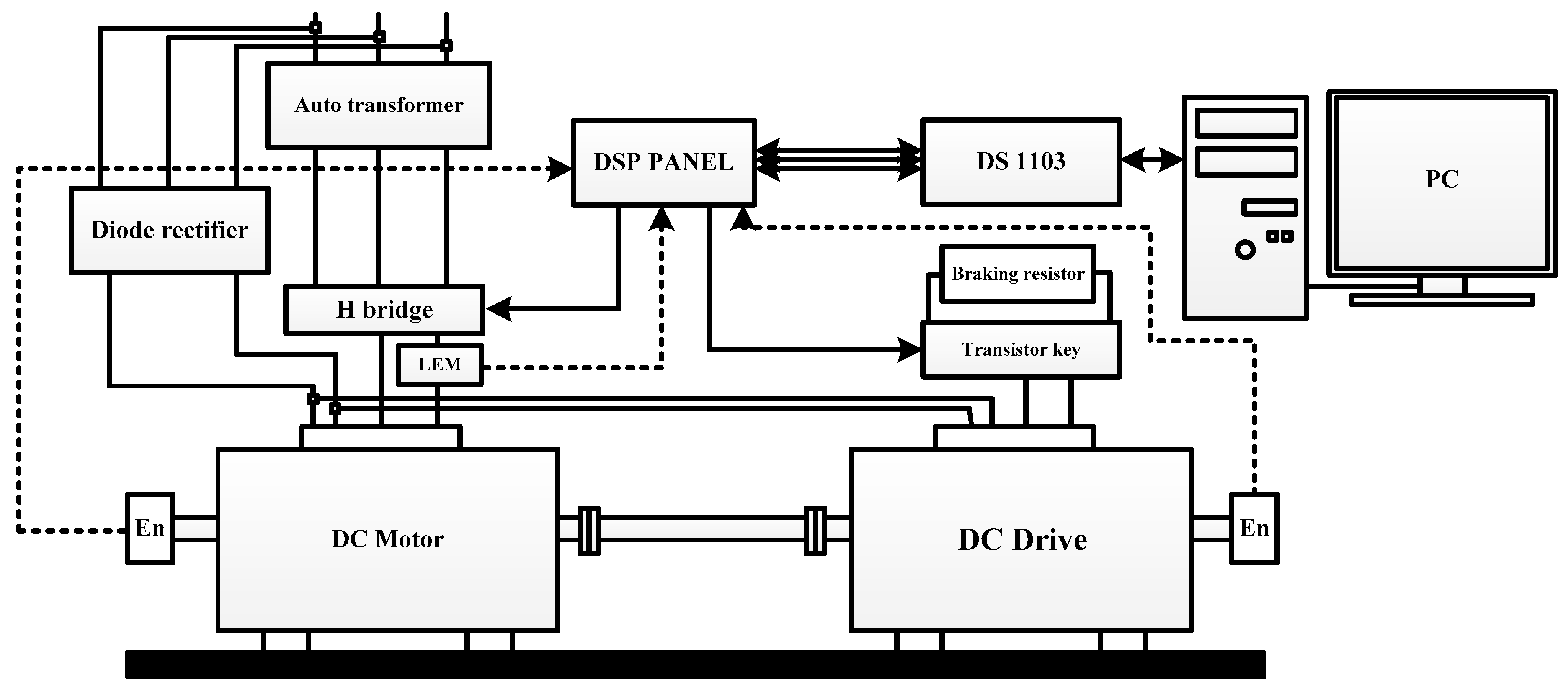
4. Experimental Study

Experimental tests were conducted to verify the usefulness of the proposed control structure. A laboratory bench designed for testing two-mass systems is used for investigating. The stand consisted of two DC machines: one is a PZBb 22b type motor, and the other is a PZBb 22b type generator. The most important parameters of the tested machines are motor power of −0.5 kW and generator power of 0.4 kW. Nominal speed was 1450 rpm for both machines. Time constants were 0.203 s for the drive and 0.285 for the generator. The time constant for the elastic shaft (l = 0.6 m ϕ = 6 mm) was 0.0013 s. The drive motor was powered by a power electronic converter (full H-bridge structure). The control algorithm was implemented on a measurement card with a signal processor. The laboratory system was equipped with two incremental encoders mounted on the side of the drive motor and the working machine. The second encoder was not used for control, and it was only used to check the correct operation of the system. The motor current was measured using a LEM sensor. The layout of the laboratory test stand is shown in Figure 10.
As can be concluded from the theoretical considerations, the control structure with two additional feedbacks is a generalization of two structures with one single additional feedback. For this reason, it was adopted for this study.
For the tests, a similar test scenario was adopted as for the simulation studies. The value of the damping coefficient was assumed to be 0.7 and different values of the resonant pulsation: ω = 30, 45 and 60. Figure 11 shows the speed transients of the driving motor and the load machine as well as the driving and torsional torques of the tested cases.
As can be seen from the transients presented in Figure 11, the proposed control system works correctly. The system with the assumed value of resonant pulsation p = 30 (Figure 11a,b) has the smallest dynamics. The rise time of the load machine speed in this case is about 100 ms, and the maximum driving torque value approaches one. Increasing the value of the system pulsation to 45 increases the dynamics of the system. The rise time of both speeds (motor and load) is shortened. At the same time, the values of torques in the system increase. The system with p = 60 has the highest dynamics. The shape of the speed of the load machine is smooth and in accordance with the theoretical assumptions. Comparing the transients shown in Figure 8 with those in Figure 11, high agreement can be observed. The slight differences are due to additional nonlinearities present in the real system (e.g., friction, nonlinear characteristics of the shaft), omitted elements in the modelling (delay of the torque loop), and finite accuracy of the identification of object parameters. These factors result in small oscillations in motor speed and torque transient evident for highest set dynamics.

5. Discussion

This paper presents issues related to the damping of torsional vibrations in a two-mass drive system. Three control structures with a PI speed controller are selected for this study: with additional feedback from the torsional torque, with additional feedback from the derivative of the torsional torque, and with additional feedback from the two abovementioned variables. Based on the analysis of the literature, theoretical considerations, simulation, and experimental studies, the following conclusions can be made:
-
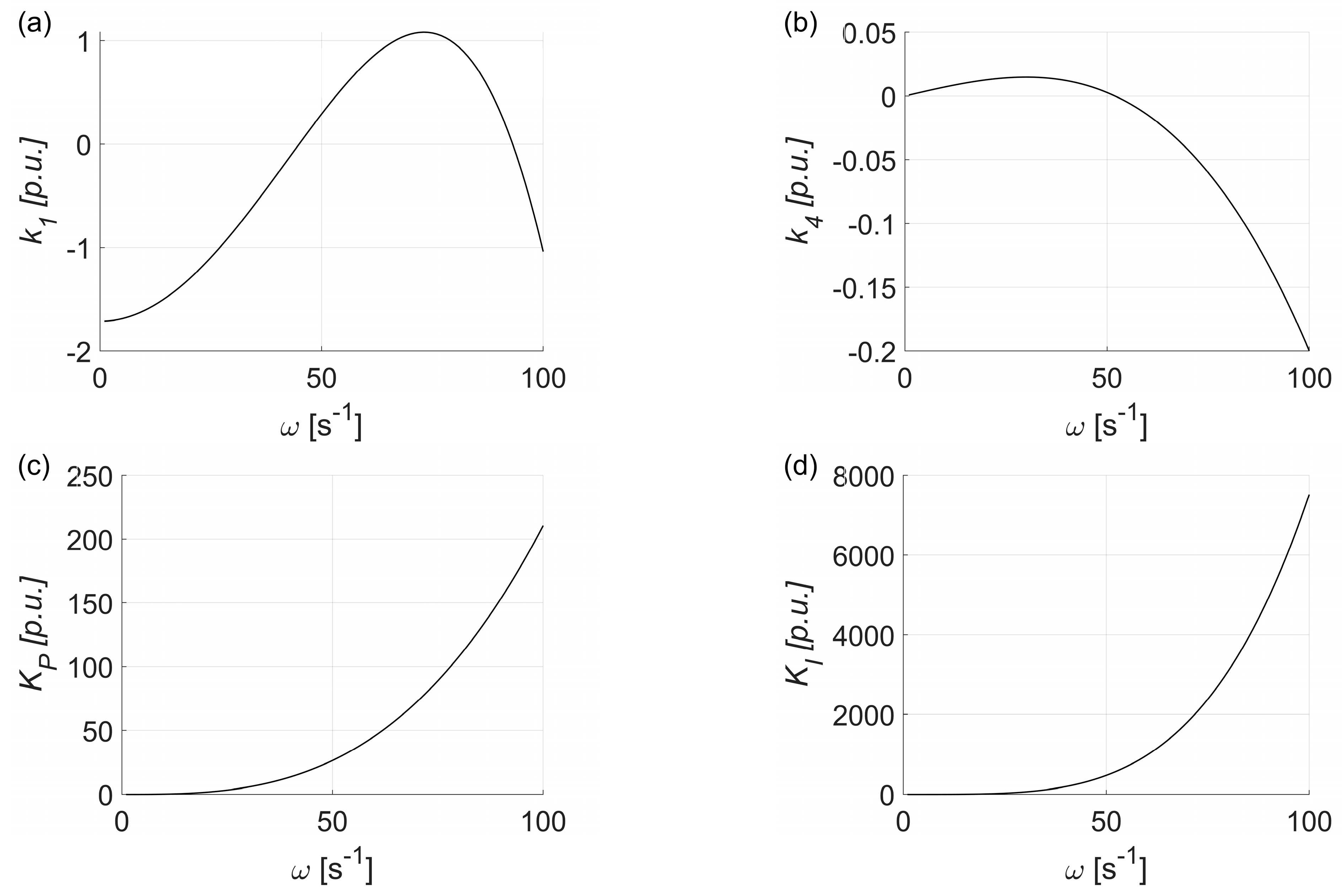
Several control methods in the literature provide active damping of torsional vibrations. One of the most popular approaches uses additional feedback from the torsional torque, and less commonly used is a structure with additional feedback from a derivative of torsional torque and with two such feedbacks. Structures with one additional feedback allow the set of the desired value of the damping ratio but not the value of the resonance pulsation. The proposed structure with two feedbacks allows the independent location of the system’s closed-loop poles. A structure with one additional feedback is a special case of a structure with two feedbacks, in which the values of k1 or k4 are zero.
-
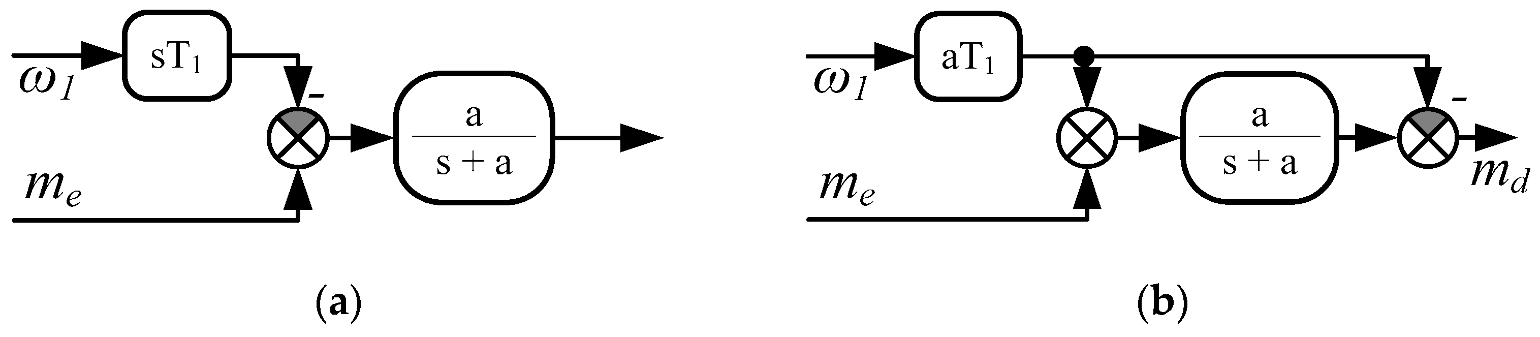
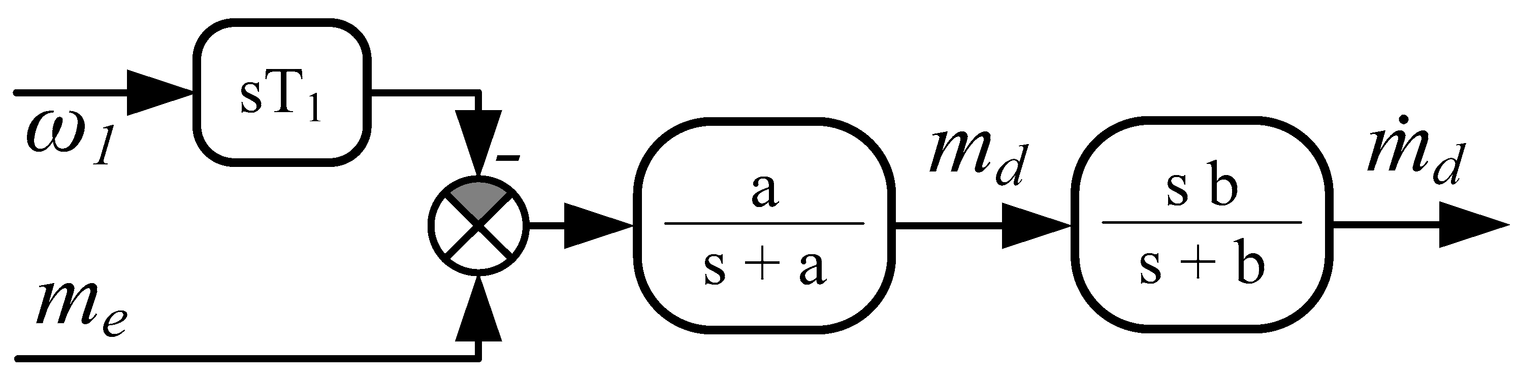
The proposed control structure with two feedbacks requires additional variables (torsional moment and its derivative). Because they are not accessible in standard drives, there is a need to apply the special estimator. According to the literature, a commonly used solution is a disturbance observer. Nevertheless, derivative operation results in the amplification of the measurement noises. To reduce the noises, the low-pass filter is applied, which, however, causes delays in the estimated signals.
-
The integral observer proposed in this paper allows increases in the estimation quality significantly as compared to the classical disturbance observer. This is because the differential operations are replaced by integral terms. The proposed observer does not include the parameters of the drive shaft and the load machine in its structure. This means that it is not sensitive to the change of these parameters. The quality of the estimated values depends only on the time constant of the driving motor, which is not changeable.
Nowadays, the commonly used approaches for the system with PI controller and feedback from the torsional torque and load speed or state controller are based on the special location of the system’s closed-loop poles. The positions of the poles are selected with the help of a metaheuristic algorithm, for instance. The drawback of this approach is connected with the requirement for information on all state variables. For this task, special estimators are applied. However, they are based on changeable parameters, which influence the estimation quality negatively and consequently the whole control structure. A similar problem appears in more advanced structures—e.g., MPC or sliding control. The structure proposed in this paper control requires information on the torsional torque and its derivative. To provide these variables, the integral observer is proposed. It is robust by definition because it does not include parameters related to the elastic shaft and load machine. Hence, the robust design problem is limited only to the selection of the control structure coefficients not to the estimator. So, consequently, the robust control problem is simpler than in currently used approaches.

6. Conclusions

In this paper, a novel PI-based control structure with additional feedback from torsional torque and its derivative is proposed. Contrary to the commonly used approaches this control structure does not use a load speed in the control algorithm. Still, the proposed control system enables the locating of the system’s closed-loop poles in the desired position. This implies that the transient of the load speed can be controlled effectively without information on this variable. For the estimation of the torsional torque and its derivative, an integral observer is proposed. Contrary to the classical disturbance observers, it does not use derivative operations. Thus, the measurement noises are not amplified by this system.
Future work will focus on the following:
-
designing an estimator that provides less noise in the estimated variables, and the use of a Kalman filter or sliding-mode observer in this task is considered
-
designing a control structure robust against changes in the parameters of load machine and mechanical coupling.

Author Contributions

Conceptualization, P.D., K.S. (Krzysztof Szabat) and S.K.; methodology, P.D., K.S. (Krzysztof Szabat) and S.K. Software, P.D., A.H.K., K.S. (Krzysztof Szabat), K.S. (Kosuke Shikata) and S.K. Validation, P.D., A.H.K., K.S. (Krzysztof Szabat), K.S. (Kosuke Shikata) and S.K. Formal analysis, P.D., K.S. (Krzysztof Szabat) and S.K. Investigation, P.D., A.H.K., K.S. (Krzysztof Szabat), K.S. (Kosuke Shikata) and S.K. Resources, P.D., A.H.K., K.S. (Krzysztof Szabat), K.S. (Kosuke Shikata) and S.K. Data curation, P.D., A.H.K., K.S. (Krzysztof Szabat), K.S. (Kosuke Shikata) and S.K.; Writing—original draft preparation, K.S. (Krzysztof Szabat). Writing—review and editing, P.D., A.H.K., K.S. (Krzysztof Szabat), K.S. (Kosuke Shikata) and S.K.; Visualization, P.D., A.H.K., K.S. (Krzysztof Szabat), K.S. (Kosuke Shikata) and S.K.; Supervision, P.D., K.S. (Krzysztof Szabat) and S.K.; Project administration, P.D., K.S. (Krzysztof Szabat) and S.K.; Funding acquisition, K.S. (Krzysztof Szabat). All authors have read and agreed to the published version of the manuscript.

Funding

This research received no external funding.

Data Availability Statement

The original contributions presented in the study are included in the article, further inquiries can be directed to the corresponding author.

Conflicts of Interest

The authors declare no conflicts of interest.

References

  1. Nguyen, V.B.; Bui, X.C. Hybrid Vibration Control Algorithm of a Flexible Manipulator System. Robotics 2023, 12, 73. [Google Scholar] [CrossRef]
  2. Zawirski, K.; Brock, S.; Nowopolski, K. Recursive Neural Network as a Multiple Input–Multiple Output Speed Controller for Electrical Drive of Three-Mass System. Energies 2024, 17, 172. [Google Scholar] [CrossRef]
  3. Liu, Y.; Song, B.; Zhou, X.; Gao, Y.; Chen, T. An Adaptive Torque Observer Based on Fuzzy Inference for Flexible Joint Application. Machines 2023, 11, 794. [Google Scholar] [CrossRef]
  4. Kabziński, J.; Mosiołek, P. Integrated, Multi-Approach, Adaptive Control of Two-Mass Drive with Nonlinear Damping and Stiffness. Energies 2021, 14, 5475. [Google Scholar] [CrossRef]
  5. Chen, L.; Du, X.; Hu, B.; Blaabjerg, F. Drivetrain Oscillation Analysis of Grid Forming Type-IV Wind Turbine. IEEE Trans. Energy Convers. 2022, 37, 2321–2337. [Google Scholar] [CrossRef]
  6. Rudniev, Y.; Romanchenko, J.; Morneva, M. Investigation of Oscillatory Processes in Mechatronic Systems with a Robust H∞-controller. In Proceedings of the 2023 IEEE 5th International Conference on Modern Electrical and Energy System (MEES), Kremenchuk, Ukraine, 27–30 September 2023; pp. 1–6. [Google Scholar] [CrossRef]
  7. Yamada, S.; Fujimoto, H. Precise Joint Torque Control Method for Two-inertia System with Backlash Using Load-side Encoder. IEEJ J. Ind. Appl. 2019, 8, 75–83. [Google Scholar] [CrossRef]
  8. Li, P.; Wang, L.; Zhong, B.; Zhang, M. Linear Active Disturbance Rejection Control for Two-Mass Systems Via Singular Perturbation Approach. IEEE Trans. Ind. Inform. 2022, 18, 3022–3032. [Google Scholar] [CrossRef]
  9. Sakaino, S.; Kitamura, T.; Mizukami, N.; Tsuji, T. High-Precision Control for Functional Electrical Stimulation Utilizing a High-Resolution Encoder. IEEJ J. Ind. Appl. 2021, 10, 124–133. [Google Scholar] [CrossRef]
  10. Wu, T.-Y.; Chen, C.-Y. Active vibration isolation on electromechanical coupling suspension system of a quar-ter-vehicle via modal space controller design. J. Vib. Control 2024, 2024, 10775463241252190. [Google Scholar] [CrossRef]
  11. Yang, T.; Xu, F.; Zhao, S.; Li, T.; Yang, Z.; Wang, Y.; Liu, Y. A High-Certainty Visual Servo Control Method for a Space Manipulator with Flexible Joints. Sensors 2023, 23, 6679. [Google Scholar] [CrossRef]
  12. Stanislawski, R.; Tapamo, J.-R.; Kaminski, M. Virtual Signal Calculation Using Radial Neural Model Applied in a State Controller of a Two-Mass System. Energies 2023, 16, 5629. [Google Scholar] [CrossRef]
  13. Liu, X.; Qiu, J.; Wang, Y.; Kambrath, J.K.; Loh, P.C.; Blaabjerg, F.; Gupta, A.K. Torsional Vibration Suppression Control for Inverter-Driven Multi-Rotating Mass System Using Non-Ideal Generalized Integrator. IEEE Trans. Power Electron. 2023, 39, 2594–2607. [Google Scholar] [CrossRef]
  14. Radionov, A.A.; Karandaev, A.S.; Gasiyarov, V.R.; Loginov, B.M.; Gartlib, E.A. Development of an Automatic Elastic Torque Control System Based on a Two-Mass Electric Drive Coordinate Observer. Machines 2021, 9, 305. [Google Scholar] [CrossRef]
  15. Łuczak, D. Nonlinear Identification with Constraints in Frequency Domain of Electric Direct Drive with Multi-Resonant Mechanical Part. Energies 2021, 14, 7190. [Google Scholar] [CrossRef]
  16. Kraus, K.; Šika, Z.; Beneš, P.; Krivošej, J.; Vyhlídal, T. Mechatronic robot arm with active vibration absorbers. J. Vib. Control. 2020, 26, 1145–1156. [Google Scholar] [CrossRef]
  17. Wang, Y.; Zheng, Q.; Zhang, H.; Miao, L. Adaptive Control and Predictive Control for Torsional Vibration Suppression in Helicopter/Engine System. IEEE Access 2018, 6, 23896–23906. [Google Scholar] [CrossRef]
  18. Wu, S.-T.; Lian, S.-H.; Chen, S.-H. Vibration control of a flexible beam driven by a ball-screw stage with adaptive notch filters and a line enhancer. J. Sound Vib. 2015, 348, 71–87. [Google Scholar] [CrossRef]
  19. Zhang, G.; Furusho, J. Speed control of two-inertia system by PI/PID control. IEEE Trans. Ind. Electron. 2000, 47, 603–609. [Google Scholar] [CrossRef]
  20. Goubej, M. Fundamental performance limitations in PID controlled elastic two-mass systems. In Proceedings of the 2016 IEEE International Conference on Advanced Intelligent Mechatronics (AIM), Banff, AB, Canada, 12–15 July 2016; pp. 828–833. [Google Scholar] [CrossRef]
  21. Szabat, K.; Orlowska-Kowalska, T. Vibration Suppression in a Two-Mass Drive System Using PI Speed Controller and Additional Feedbacks—Comparative Study. IEEE Trans. Ind. Electron. 2007, 54, 1193–1206. [Google Scholar] [CrossRef]
  22. Sugiura, K.; Hori, Y. Vibration suppression in 2- and 3-mass system based on the feedback of imperfect derivative of the estimated torsional torque. IEEE Trans. Ind. Electron. 1996, 43, 56–64. [Google Scholar] [CrossRef]
  23. Sariyildiz, E.; Ohnishi, K. A Guide to Design Disturbance Observer. J. Dyn. Syst. Meas. Control. 2013, 136, 021011. [Google Scholar] [CrossRef]
  24. Li, X.; Shang, D.; Li, H.; Li, F. Resonant Suppression Method Based on PI control for Serial Manipulator Servo Drive System. Sci. Prog. 2020, 103, 0036850420950130. [Google Scholar] [CrossRef] [PubMed]
  25. Thomsen, S.; Hoffmann, N.; Fuchs, F.W. PI Control, PI-Based State Space Control, and Model-Based Predictive Control for Drive Systems With Elastically Coupled Loads—A Comparative Study. IEEE Trans. Ind. Electron. 2011, 58, 3647–3657. [Google Scholar] [CrossRef]
  26. Szczepanski, R.; Kaminski, M.; Tarczewski, T. Auto-Tuning Process of State Feedback Speed Controller Applied for Two-Mass System. Energies 2020, 13, 3067. [Google Scholar] [CrossRef]
  27. Saarakkala, S.E.; Hinkkanen, M. State-Space Speed Control of Two-Mass Mechanical Systems: Analytical Tuning and Experimental Evaluation. IEEE Trans. Ind. Appl. 2014, 50, 3428–3437. [Google Scholar] [CrossRef]
  28. Serkies, P.; Szabat, K. Effective damping of the torsional vibrations of the drive system with an elastic joint based on the forced dynamic control algorithms. J. Vib. Control. 2019, 25, 2225–2236. [Google Scholar] [CrossRef]
  29. Huang, Y.; Zhang, Z.; Huang, W.; Chen, S. DC-Link Voltage Regulation for Wind Power System by Complementary Sliding Mode Control. IEEE Access 2019, 7, 22773–22780. [Google Scholar] [CrossRef]
  30. Wang, C.; Liu, F.; Xu, J.; Pan, J. A SMC-based Accurate and Robust Load Speed Control Method for Elastic Servo System. IEEE Trans. Ind. Electron. 2023, 71, 2300–2308. [Google Scholar] [CrossRef]
  31. Chang, H.; Lu, S.; Huang, G.; Zheng, S.; Song, B. An extended active resonance suppression scheme based on a dual-layer network for high-performance double-inertia drive system. IEEE Trans. Power Electron. 2023, 38, 13717–13729. [Google Scholar] [CrossRef]
  32. Orlowska-Kowalska, T.; Kaminski, M.; Szabat, K. Implementation of a Sliding-Mode Controller With an Integral Function and Fuzzy Gain Value for the Electrical Drive With an Elastic Joint. IEEE Trans. Ind. Electron. 2009, 57, 1309–1317. [Google Scholar] [CrossRef]
  33. Wai, R.-J. Fuzzy Sliding-Mode Control Using Adaptive Tuning Technique. IEEE Trans. Ind. Electron. 2007, 54, 586–594. [Google Scholar] [CrossRef]
  34. Pajchrowski, T.; Siwek, P.; Wójcik, A. Adaptive controller design for electric drive with variable parameters by Reinforcement Learning method. Bull. Pol. Acad. Sci. Tech. Sci. 2020, 68, 1019–1030. [Google Scholar] [CrossRef]
  35. Jastrzębski, M.; Kabziński, J.; Mosiołek, P. Adaptive Position Control for Two-Mass Drives with Nonlinear Flexible Joints. Energies 2024, 17, 425. [Google Scholar] [CrossRef]
  36. Wang, X.; Ufnalski, B.; Grzesiak, L.M. Adaptive speed control in the PMSM drive for a non-stationary repetitive process using particle swarms. In Proceedings of the 2016 10th International Conference on Compatibility, Power Electronics and Power Engineering (CPE-POWERENG), Bydgoszcz, Poland, 29 June–1 July 2016; pp. 464–471. [Google Scholar]
  37. Szabat, K.; Orlowska-Kowalska, T. Application of the Kalman Filters to the High-Performance Drive System With Elastic Cou-pling. IEEE Trans. Ind. Electron. 2012, 59, 4226–4235. [Google Scholar] [CrossRef]
  38. Quevedo, D.E.; Aguilera, R.P.; Geyer, T. Predictive control in power electronics and drives: Basic concepts, theory, and methods. Adv. Intell. Control Power Electron. Drives 2014, 2014, 181–226. [Google Scholar]
  39. Cychowski, M.; Szabat, K.; Orlowska-Kowalska, T. Constrained Model Predictive Control of the Drive System With Mechanical Elasticity. IEEE Trans. Ind. Electron. 2009, 56, 1963–1973. [Google Scholar] [CrossRef]
  40. Šlapák, V.; Kyslan, K.; Lacko, M.; Fedák, V.; Ďurovský, F. Finite Control Set Model Predictive Speed Control of a DC Motor. Math. Probl. Eng. 2016, 2016, 9571972. [Google Scholar] [CrossRef]
  41. Serkies, P. A novel predictive fuzzy adaptive controller for a two-mass drive system, Bulletin of the Polish Academy of Sciences. Tech. Sci. 2018, 66, 37–47. [Google Scholar]
  42. Wang, C.; Yang, M.; Zheng, W.; Long, J.; Xu, D. Vibration Suppression With Shaft Torque Limitation Using Explicit MPC-PI Switching Control in Elastic Drive Systems. IEEE Trans. Ind. Electron. 2015, 62, 6855–6867. [Google Scholar] [CrossRef]
  43. Yang, M.; Wang, C.; Xu, D.; Zheng, W.; Lang, X. Shaft Torque Limiting Control Using Shaft Torque Compensator for Two-Inertia Elastic System With Backlash. IEEE/ASME Trans. Mechatron. 2016, 21, 2902–2911. [Google Scholar] [CrossRef]
  44. Serkies, P.; Gorla, A. Implementation of PI and MPC-Based Speed Controllers for a Drive with Elastic Coupling on a PLC Controller. Electronics 2021, 10, 3139. [Google Scholar] [CrossRef]
  45. Fuentes, E.J.; Silva, C.A.; Yuz, J.I. Predictive Speed Control of a Two-Mass System Driven by a Permanent Magnet Synchronous Motor. IEEE Trans. Ind. Electron. 2011, 59, 2840–2848. [Google Scholar] [CrossRef]
  46. Kabziński, J.; Mosiołek, P. Observer-Based, Robust Position Tracking in Two-Mass Drive System. Energies 2022, 15, 9093. [Google Scholar] [CrossRef]
  47. Krisztián, H.; Kuslits, M. Dynamic performance of estimator-based speed sensorless control of induction machines using extended and unscented Kalman filters. Power Electron. Drives 2018, 3, 129–144. [Google Scholar]
  48. Zhu, M.; Xiao, S.; Yu, F. Torque Estimation for Robotic Joint with Harmonic Drive Transmission Based on System Dynamic Characteristics. J. Syst. Eng. Electron. 2022, 33, 1320–1331. [Google Scholar]
  49. Wang, Y.; Li, J. Equivalent-Input-Disturbance-Based Speed Control of Two-Mass System Using Generalized Extended State Observer. In Proceedings of the 2023 10th International Forum on Electrical Engineering and Automation (IFEEA), Nanjing, China, 3–5 November 2023; pp. 870–873. [Google Scholar]
  50. Wang, C.; Liu, J.; Xin, L.; Li, G.; Pan, J. Design of Full-Order State Observer for Two-Mass Joint Servo System Based on the Fixed Gain Filter. IEEE Trans. Power Electron. 2022, 37, 10466–10475. [Google Scholar] [CrossRef]
Figure 1. A diagram of the two-mass system.
Energies 17 04786 g001
Figure 2. A block diagram of the proposed control structure.
Energies 17 04786 g002
Figure 3. Control system coefficients as a function of the resonant pulsation: k1 coefficient (a), k4 coefficient (b), KP coefficient (c), KI coefficient (d).
Energies 17 04786 g003
Figure 4. Block diagram of the disturbance observer: direct (a) and transformed (b) form.
Energies 17 04786 g004
Figure 5. Block diagram of the classical system for determination of disturbance torque and its derivative.
Energies 17 04786 g005
Figure 6. Block diagram of the integral observer for disturbance torque and its first derivative estimation.
Energies 17 04786 g006
Figure 7. Transients of the two-mass system: motor speed (black) and load speed (blue) (a,c,e) and electromagnetic torque (black) and torsional torque (blue) (b,d,f) for the system with single additional feedback from torsional torque (a,b), derivative of the torsional torque and x1 poles placement (c,d), and derivative of the torsional torque x2 poles placement (e,f) for damping factor 0.7.
Energies 17 04786 g007
Figure 8. Transients of the two-mass system: motor speed (black) and load speed (blue) (a,c,e) and electromagnetic torque (blue) and torsional torque (black) (b,d,f) for system with both additional feedbacks from torsional torque and derivative of the torsional torque for ω = 30 (a,b), 45 (c,d), and 60 (e,f) and damping factor 0.7.
Energies 17 04786 g008
Figure 9. The transients of the torsional moment (a) and its first derivative (c) as well as the estimation errors for both variables (b,d) for different values of resonant pulsation p = 300, 150, and 100.
Energies 17 04786 g009
Figure 10. Diagram of the laboratory system.
Energies 17 04786 g010
Figure 11. Transients of the two-mass system: motor speed (blue) and load speed (red) (a,c,e) and electromagnetic torque (red) and torsional torque (blue) (b,d,f) for system with both additional feedbacks from torsional torque and derivative of the torsional torque for ω = 30 (a,b), 45 (c,d), and 60 (e,f)—experimental results.
Energies 17 04786 g011
Table 1. Properties of the selected control structures.
Signal of Load Speed RequiredRemarksProperties
PI-based control structure with one additional feedbackYes/No Simple or complicated estimator (depends on the type of feedback)Limited dynamic
PI-based control structure with feedback from torsional torque and motor speedYesComplicated estimator neededGood dynamic
State controllerYesComplicated estimator neededGood dynamic
FDC-based control structureYesMore complicated estimator neededGood dynamic, robust to load torque changes
Adaptive systemYesMore complicated estimator neededGood dynamic, robust to parameter changes
Sliding-mode systemYesMore complicated estimator neededVery good dynamic, robust to parameter changes
MPC systemYesComplicated estimator neededVery good dynamic, complicated algorithm, Constraints directly addressed
Proposed control structureNoSimple estimator neededGood dynamic
Disclaimer/Publisher’s Note: The statements, opinions and data contained in all publications are solely those of the individual author(s) and contributor(s) and not of MDPI and/or the editor(s). MDPI and/or the editor(s) disclaim responsibility for any injury to people or property resulting from any ideas, methods, instructions or products referred to in the content.

