Abstract
The current source inverter (CSI) has become the main grid-connected interface of distributed generation systems due to its advantages, such as boost capability, current controllability, and short-circuit protection capability. However, in weak grids, the grid-connected CSI that uses a phase-locked loop to achieve grid voltage synchronization has problems, such as instability in the fundamental positive-sequence voltage phase detection at the point of common coupling and instability in the current loop control, which seriously hamper the promotion and application of the CSI and its interconnected systems. For this reason, this paper proposes a sliding mode observer-based phase-locking strategy for the CSI. The strategy proposes a sliding mode observer for grid voltage phase detection, so that the grid current can directly follow the grid voltage, solving the problem of inconsistency or distortion between the voltage phase of the point of common coupling and the grid voltage phase in weak grids. On this basis, the grid impedance is regarded as part of the CL filter, and a robust parameter design method is proposed for the grid current closed-loop control in weak grids, which achieves robust operation of a CSI in weak grids. Finally, an experimental platform for a single-phase grid-connected CSI is built to verify the effectiveness and feasibility of the proposed scheme.
1. Introduction
The current source inverter (CSI), due to its advantages, such as boost capability, current controllability, and short-circuit protection capability, has been gradually applied to scenarios such as uninterruptible power supply systems [1], electric aircraft power systems [2], photovoltaic power systems [3], and wind power generation systems [4]. However, the public power grid with power electronics exhibits weak grid characteristics [5], which seriously affects the phase detection of the grid fundamental voltage at the point of common coupling (PCC) by the phase-locked loop (PLL), resulting in instability problems in the PLL-based grid voltage following a control strategy in weak grids [6,7,8,9].
Due to the duality of the topological structures of the CSI and voltage source inverter (VSI) [10], the research on the grid-connected VSI with an L or LCL filter in weak grids can be used as a reference. According to the small signal impedance stability criterion [11], a PLL will introduce negative incremental resistance, resulting in instability of the grid-connected system, and the increase in the bandwidth of the PLL will expand the frequency range of instability. In addition, the interaction between the PLL, current controller, and grid impedance will damage the stability of the system [12].
The grid following a control structure based on a PLL plus a current loop enables the solution to improve the stability of the grid-connected system to be developed through a PLL or grid-connected current closed loop. In the solution based on a PLL, reducing the PLL bandwidth is a way to improve the PLL equivalent impedance [13], but the fast dynamics of a PLL are contradictory to reducing the bandwidth, which reduces the dynamic response of the system. On the other hand, optimizing the PLL control structure to reshape the PLL equivalent impedance can reduce the instability caused by the negative resistance characteristics of the PLL. Khaled Mohammad Alawasa et al. [14,15] introduced the notch filter or the bandpass filter in a PLL to reshape the inverter output impedance. However, the design of the filter depends on an accurate system impedance model. Dongsheng Yang et al. [16] used a symmetrical PLL to eliminate the frequency coupling effect and combined impedance shaping to offset the negative resistance characteristics caused by the PLL. Xianfu Lin et al. [17] solved the problem of grid-connected system stability by decoupling a PLL and grid impedance through an improved PLL. Xianfu Lin et al. [18] effectively reduced the coupling between the PLL and the control system through a new type of PLL with a constant coupling effect, making the system more robust to grid impedance changes. However, the decoupling effect depends on the construction of an accurate system model, which increases the complexity of system design. Matias Berg et al. [19] compensated for the phase difference between the PCC voltage and the grid voltage caused by grid impedance through a PLL phase compensation method. However, its compensation phase strongly depends on the grid impedance measurement accuracy, which can easily lead to system instability. Leilei Guo et al. [20,21] used a PLL-independent online grid voltage observation method based on the sliding mode observer (SMO) to achieve grid voltage sensorless control for the single L-filtered grid-connected inverter, but they did not consider the impact of grid impedance on the grid current closed loop.
Improving the current control loop is also the key to improving the stable operation of the CSI. Adjusting the current controller parameters is the simplest and most feasible method. Hong Gong et al. [12] designed the controller parameters to improve the system stability based on the influence of the proportional gain of the current controller on the instability of the PLL in weak grids. However, this method will reduce the current loop control bandwidth and affect the dynamic performance of the system. Introducing additional control links is also a main method. Guoning Wang et al. [22] introduced a grid voltage feedforward control link to reshape the inverter output impedance and offset the negative resistance characteristics of the PLL. Xuehua Wang et al. [23] extracted the grid voltage from the PCC voltage through a double sampling mode and fed it forward to the current controller output. Xin Chen et al. [24] introduced the PCC voltage feedforward to the current loop to achieve dynamic compensation of the impedance phase. Donghai Zhu et al. [25] introduced a small signal compensation function based on a PLL to reduce the negative resistance effect of the PLL on the current control loop. Bin Guo et al. [26] introduced a virtual series impedance and moved the virtual impedance action point to the current controller output through an equivalent transformation of the series impedance reshaping scheme. However, in the above schemes, the multi-loop control system will increase the burden on the design of control parameters. In addition, in the existing PLL-based current control scheme, it is difficult to completely eliminate the interaction between control loops.
To address the above problems, the contributions of this paper are as follows. On the one hand, an SMO for grid voltage phase detection is proposed for a single-phase CSI, so that the grid current can directly follow the grid voltage, solving the problem of inconsistency or distortion between the phases of PCC voltage and grid voltage in weak grids. On the other hand, based on the SMO phase-locking strategy, the grid impedance is regarded as part of the CL filter, and a robust parameter design method is proposed for the grid current closed-loop control, solving the problem of robust operation of CSI in weak grids.
The comparison between the proposed SMO-based phase-locking strategy and the traditional PLL-based phase-locking strategy is shown in Table 1. Both phase-locking strategies can achieve fast tracking of the observed voltage phase and are not affected by grid frequency fluctuations. However, the PLL-based phase-locking strategy has a coupling problem between the PLL, current controller and grid impedance, which leads to the issue of weak stability of the PLL-based grid-connected system in weak grids. In comparison, the proposed SMO-based phase-locking strategy can solve the coupling problem caused by the inconsistency between the PCC voltage and grid voltage phases, thereby stabilizing the SMO-based grid-connected system in weak grids.

Table 1.
Comparison between the proposed SMO-based phase-locking strategy and the traditional PLL-based phase-locking strategy.
The rest of the paper is organized as follows. In Section 2, the unstable effect of a PLL-based phase-locking strategy on a grid-connected CSI in weak grids is discussed. In Section 3, an SMO for grid voltage phase detection is proposed to solve the problem of inconsistency between the PCC voltage phase and grid voltage phase in weak grids. In Section 4, the grid impedance is regarded as part of the CL filter, and a robust design method for grid current closed-loop parameters in weak grids is proposed to achieve the robustness of a grid-connected CSI to grid impedance changes under an SMO-based phase-locking strategy. In Section 5, an experimental platform is built to verify the effectiveness of the proposed strategy and parameter design method. Finally, a conclusion is drawn in Section 6.
2. Traditional Control Strategy Based on PLL
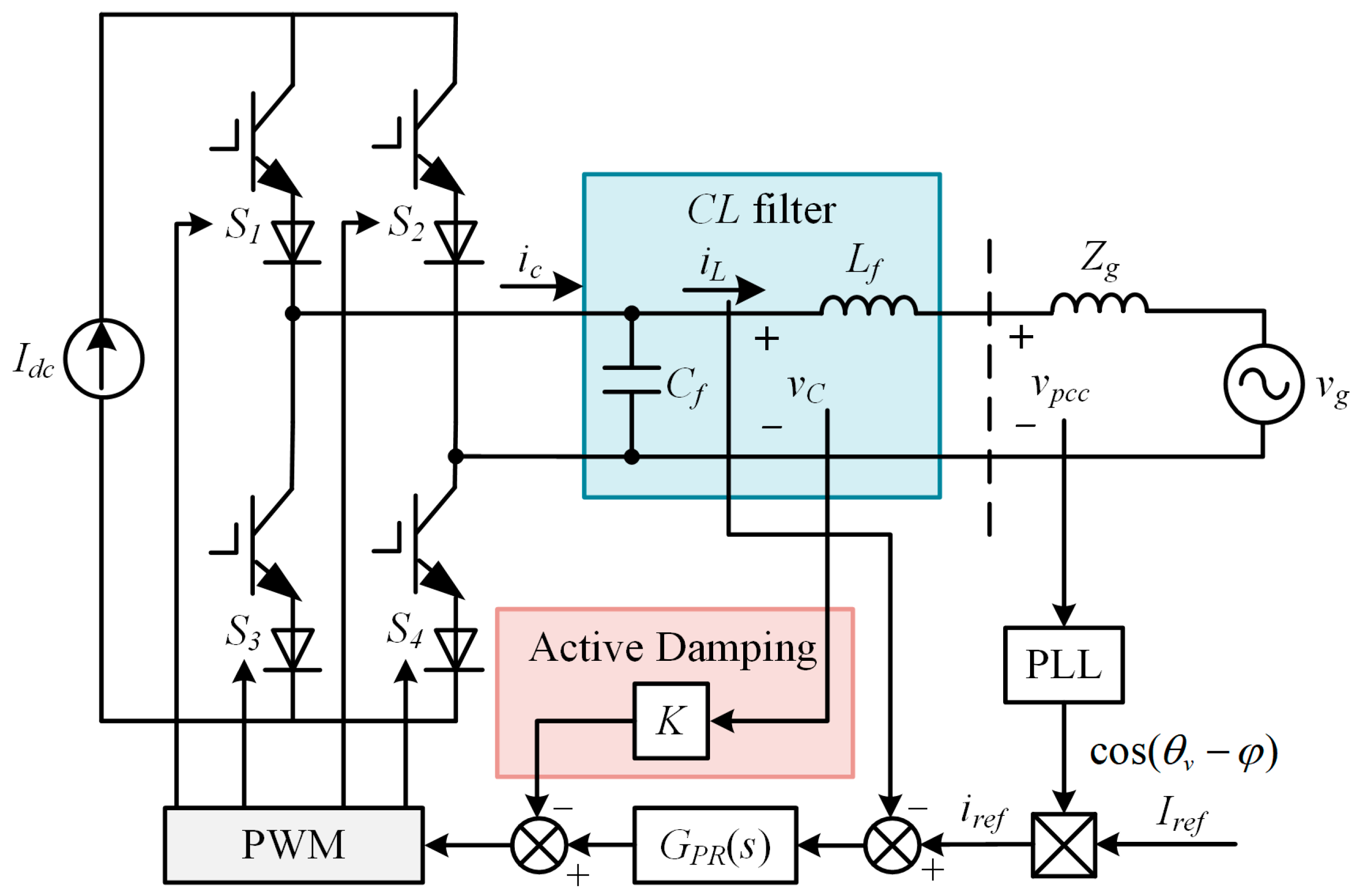
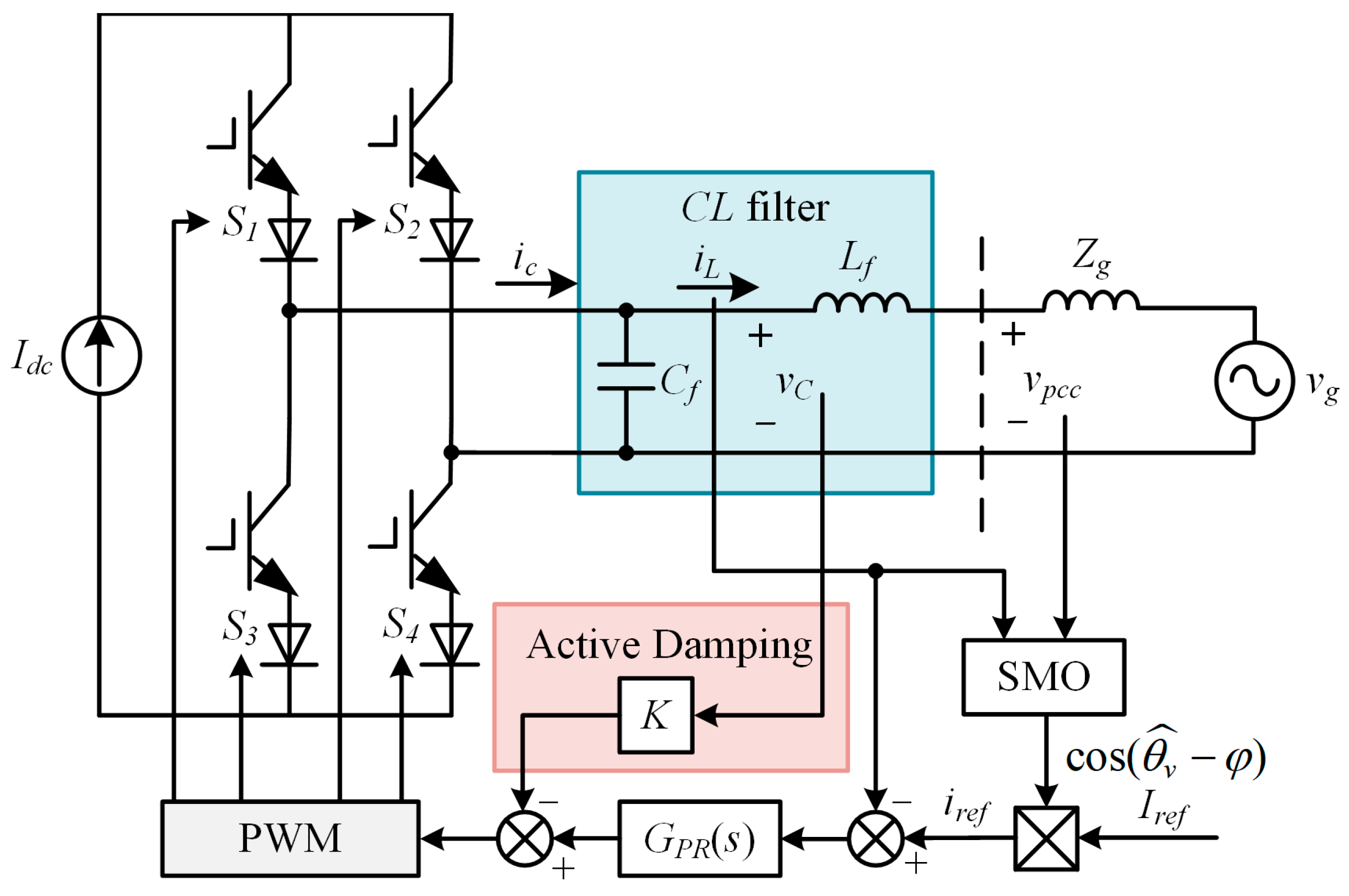
The topology of a single-phase grid-connected CSI using a traditional PLL-based grid following a control strategy is shown in Figure 1. Since the current pulsation in the large inductor on the DC side of the CSI is minimal, the DC side can be regarded as a constant current source, and its impact on the control characteristics of the AC-side grid-connected current during the PWM modulation process can be ignored. To have reverse voltage resistance, the power switch device is composed of an IGBT and a diode in series. The inverter output is connected to the infinite AC grid through a CL filter and line impedance. The PLL is used to detect the phase θv of the PCC voltage vpcc, and θv is further combined with the current amplitude given Iref and the power factor angle φ to generate a current reference iref. To suppress the CL resonance spike, active damping is achieved through capacitor voltage proportional feedback, and K is the damping coefficient. GPR(s) represents a proportional and resonant (PR) controller. PWM represents pulse width modulation. Idc is the DC current, Lf and Cf are the filter inductance and capacitance, respectively, Zg is the equivalent impedance of the grid, ic and iL are the inverter output current and grid current, respectively, and vC and vg are the filter capacitor voltage and grid voltage, respectively.
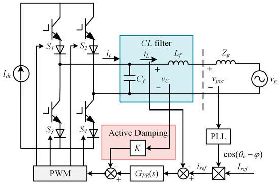
Figure 1.
System structure of single-phase grid-connected CSI based on PLL phase locking.
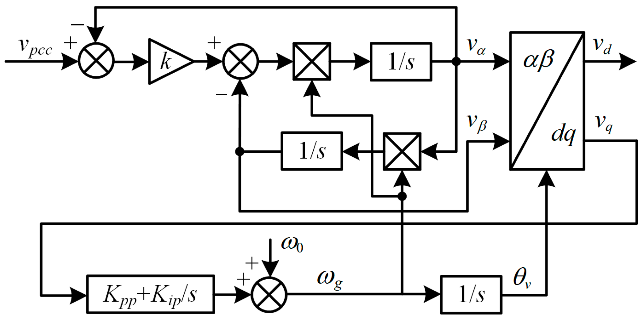
As a typical PLL, the PLL based on the second order generalized integrator (SOGI) has good harmonic suppression capability [27], and its control block diagram is shown in Figure 2. k is the proportional factor for adjusting the SOGI bandwidth, ω0 is the fundamental angular frequency, Vgm is the grid voltage amplitude, and Kpp and Kip are the proportional coefficient and integral coefficient of the regulator, respectively.
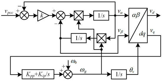
Figure 2.
Block diagram of SOGI-PLL.
According to the system structure shown in Figure 1 and the SOGI-PLL control block diagram shown in Figure 2, affected by the PI regulator in the PLL, the PCC phase information θv obtained by the PLL has phase angle fluctuations or deviations under small signal disturbances, which makes the inverter synchronous rotating coordinate system and the grid rotating coordinate system corresponding to the PCC voltage not coincident, and further leads to the deterioration of the tracking effect of the grid current on the voltage phase. In addition, the grid current will affect the PCC voltage through the grid impedance, resulting in a vicious cycle and system oscillation or divergence. As the grid impedance increases, the coupling degree of the PLL, current controller, and grid impedance intensifies, making the grid-connected CSI less stable in weak grids.
3. Stable Control Strategy Based on SMO
In weak grids, the relationship between the PCC voltage vpcc and the grid voltage vg can be derived as
where Lg and Rg are the equivalent inductance and resistance of the power grid.
According to the mathematical model shown in Equation (1), the SMO is established as
where is the estimated value of the grid current, M is the sliding mode gain, and sgn( ) is the sign function.
According to Equations (1) and (2), the relation satisfied by the grid current observation error −iL can be obtained as
For the stability analysis of the SMO, the Lyapunov function is selected as
The derivative of Equation (4) can be obtained as
To satisfy the stability condition of the Lyapunov function, dV/dt < 0 must be satisfied. According to Equation (5), the sufficient condition for the sliding mode gain M to satisfy dV/dt < 0 can be derived as
Under this condition, the convergence of the SMO can be ensured, that is, = 0. The larger the value of M, the faster the SMO converges, but the larger the sliding mode noise; the smaller the value of M, the slower the SMO converges, but the smaller the sliding mode noise. Therefore, the selection of M needs to take into account both rapidity and anti-interference. However, under the action of the low-pass filter (LPF) mentioned later, the sliding mode noise can be effectively filtered out. Therefore, the value of M can be much larger than Vgm to improve the dynamic performance of the SMO.
Substituting = 0 into Equation (3), the estimated value of the grid voltage can be obtained as
The sliding mode term on the right side of Equation (7) contains the grid voltage fundamental signal, background harmonics, and sliding mode noise. To extract the fundamental signal, an LPF is applied to the observation result, shown as
where is the estimated value of the grid voltage after filtering, and ωcL is the cutoff frequency of the LPF.
However, the LPF will cause the extracted fundamental signal to have amplitude attenuation and phase lag. To obtain the grid voltage phase, phase compensation is required. The phase lag caused by the LPF can be expressed as
According to Equation (9), the phase compensation of the estimated value depends on the grid frequency. In addition, the grid voltage estimate includes two parts, amplitude and phase, and the phase part needs to be extracted separately. When the SMO is applied to a three-phase system, the accurate grid voltage can be obtained through multiple low-pass-filtered α and β components of the three-phase voltage [20]. However, when the SMO is applied to a single-phase system, the construction process of the α and β components of the single-phase voltage is relatively complicated. Therefore, this paper applies a frequency-adaptive SOGI to avoid the construction of multiple α and β components.
For the frequency-adaptive SOGI shown in Figure 2, taking as the input signal, on the one hand, the frequency locking purpose can be achieved to obtain the grid frequency ωg required for phase compensation, and on the other hand, two completely orthogonal signals, and , can be generated, so that the phase estimate of the filtered grid voltage can be expressed as
Furthermore, the phase estimate of the grid voltage at the grid frequency can be expressed as
The actual control system is a discrete system, so the SMO shown in Equation (2) needs to be converted into a differential equation form, shown as
where and are estimated values of the grid current in the current sampling period and the previous sampling period, respectively, and Ts is the sampling period.
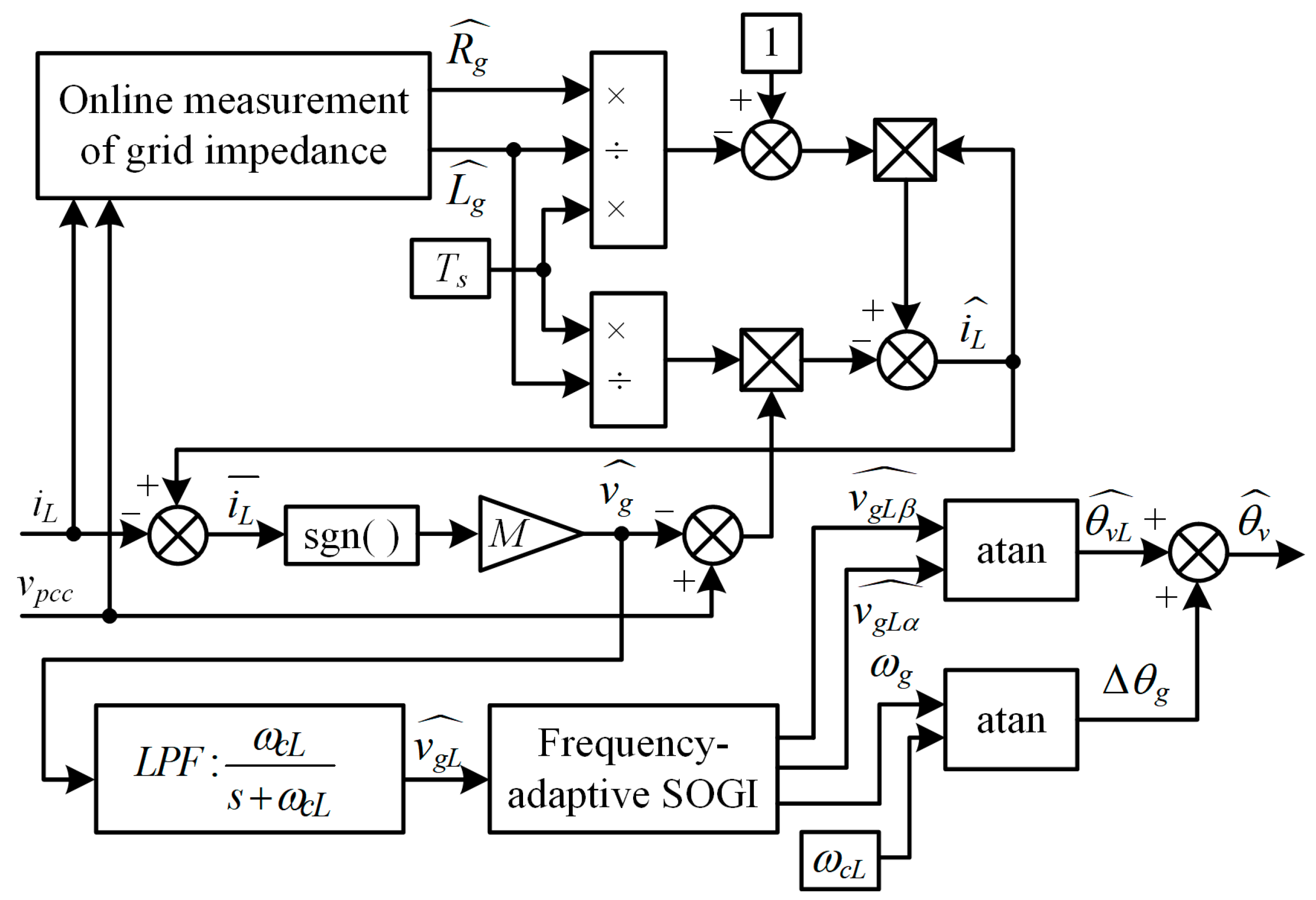
The measured values and of the grid equivalent impedance in the SMO are obtained by online grid impedance measurement [28]. The topological structures of the designed SMO for observing the grid voltage phase and the single-phase grid-connected CSI using the SMO-based stable control strategy are shown in Figure 3 and Figure 4, respectively.
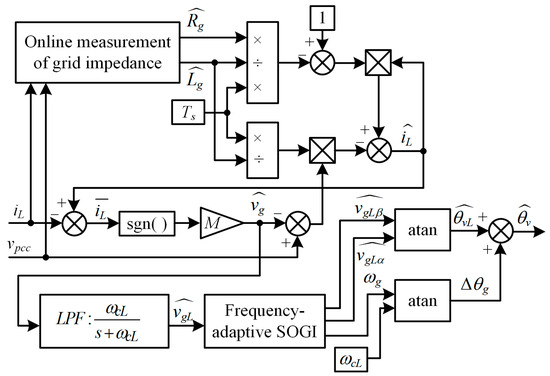
Figure 3.
Structure of SMO.

Figure 4.
System structure of single-phase grid-connected CSI based on SMO phase locking.
4. Parameter Design under Proposed SMO-Based Phase-Locking Strategy
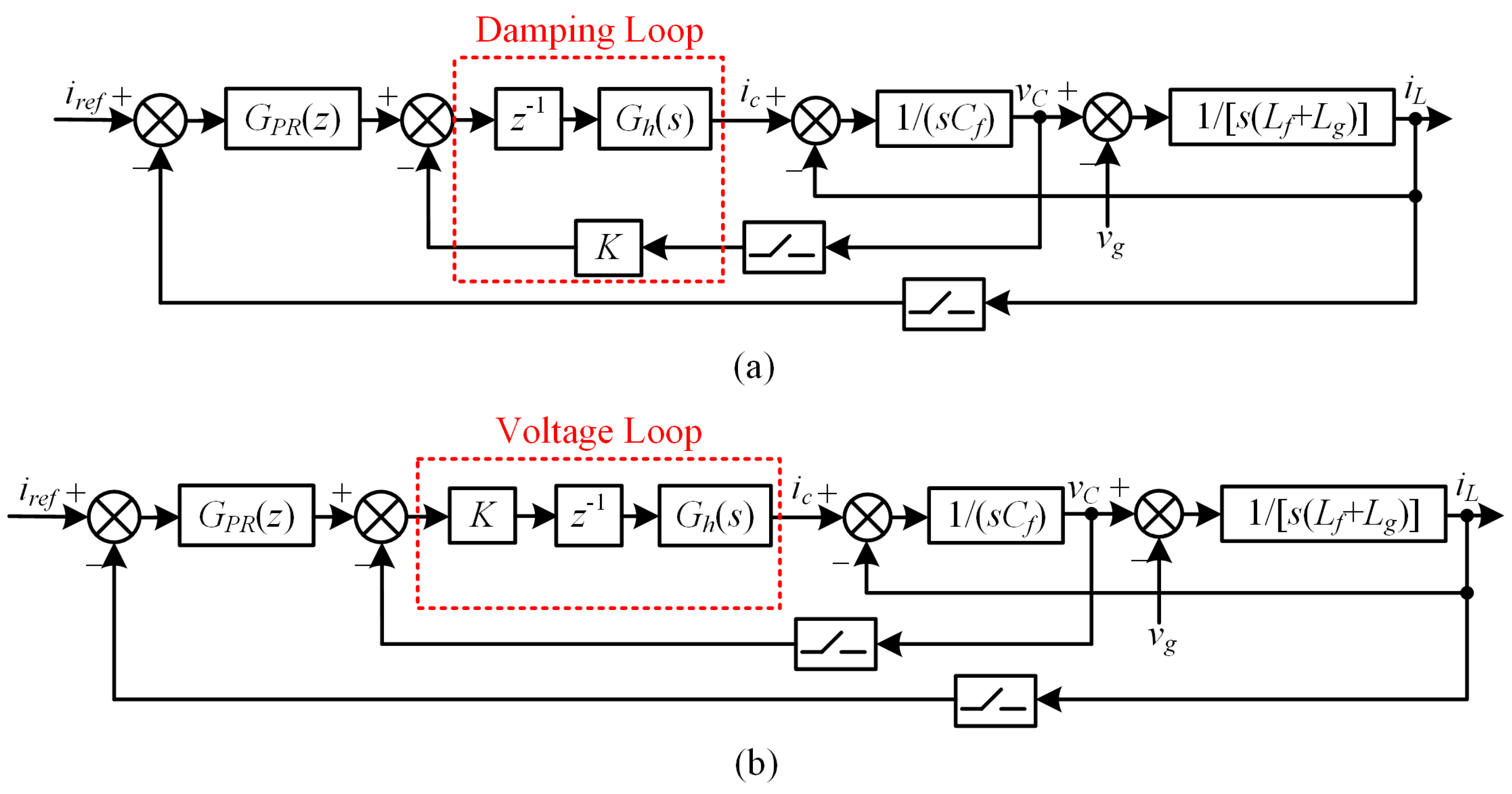
Focusing on the worst operating conditions of the grid-connected CSI, the grid equivalent resistance Rg is ignored as a passive component. In addition, the role of the SMO is to obtain the grid voltage phase, which is combined with the current amplitude given Iref and the power factor angle φ to generate the current reference iref. Under the premise that the dynamic response of the SMO is fast enough, its influence on the current control loop can be ignored. Therefore, the mathematical model of the SMO is not considered in the following parameter design and is represented by iref. Based on the above analysis, the current control block diagram in the mixed s- and z-domain, when considering the influence of the grid impedance on the grid current closed loop, is shown in Figure 5a. This structure of the current outer loop and damping inner loop can be easily found to be equivalent to the structure of the current outer loop and voltage inner loop shown in Figure 5b [29].
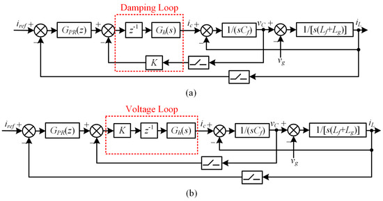
Figure 5.
Block diagram of current control based on SMO phase locking in mixed s- and z-domain. (a) Current outer loop and damping inner loop structure. (b) Current outer loop and voltage inner loop structure.
It should be highlighted that the PWM inverter has a transfer function, KPWM = Idc/Itri, whereas Itri is the peak-to-peak amplitude of the triangular carrier. In the following analysis for the CSI system, the control output is divided by KPWM before sending as the PWM modulation reference. Furthermore, the modulated signal can be amplified by Idc and then basically restored to the control output at the inverter output. By doing so, the control parameter design will not be interfered with by the effect of KPWM, and the control block diagram will also be simplified without containing the parameter KPWM. Moreover, the one-sampling-period delay z−1 and zero-order hold (ZOH) are utilized to model the PWM generation process. Gh(s) is the transfer function of ZOH, shown as
Discretized by the Tustin discretization method with frequency pre-warping, the discrete form GPR(z) of the PR controller can be obtained as
where Kpc is the proportional gain, Krc is the resonant gain, and ωi is the bandwidth term.
Furthermore, the current control block diagram in the z-domain is shown in Figure 6. In the discrete z-domain, the system loop gain Gop(z) can be derived as
where GiL(z) and GvC(z) are the transfer functions from the inverter output current ic to the grid current iL and the capacitor voltage vC after ZOH transformation, shown as

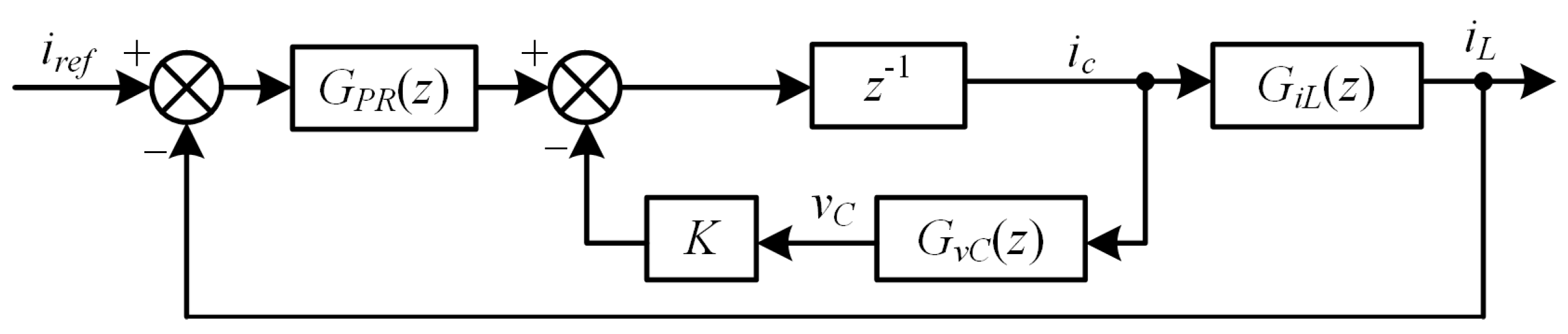
Figure 6.
Block diagram of current control based on SMO phase locking in discrete z-domain.
ωr is the resonant frequency when the grid equivalent inductance Lg is regarded as part of the CL filter, expressed as
When the effect of Lg is not considered, the resonant frequency ωr0 of the CL filter itself is expressed as
According to Equation (15), the number of poles outside the unit circle of the system open-loop transfer function depends on the following equation:
The resonant frequency fr is usually expected to be less than half of the switching frequency fsw to ensure good harmonic attenuation performance. In addition, the sampling frequency fs is set to twice fsw in this article. Therefore, the discussion on control parameter design in this article is only within the range of fr < fs/4. Use the transformation z = (1 + w)/(1 − w) to map the unit circle in the z-domain in Equation (20) to the imaginary axis in the w-domain, and then apply the Routh–Hurwitz stability criterion to obtain
When the damping coefficient K satisfies Equation (21), the system open-loop transfer function has no poles outside the unit circle. Otherwise, the system open-loop transfer function will have two poles outside the unit circle.
When performing stability analysis, the PR controller can only consider the proportional gain Kpc in the high-frequency band. Substituting Kpc for GPR(z) in Equation (15), the simplified system loop gain Gso(z) can be obtained as
According to the logarithmic frequency response stability criterion, the number Z of poles outside the unit circle of the closed-loop system is expressed as Z = P − 2N. P is the number of poles outside the unit circle of Gso(z), and N is the number of times the Gso(z) phase–frequency characteristic curve crosses −180°. If Z = 0, the closed-loop system is stable, otherwise the system is unstable.
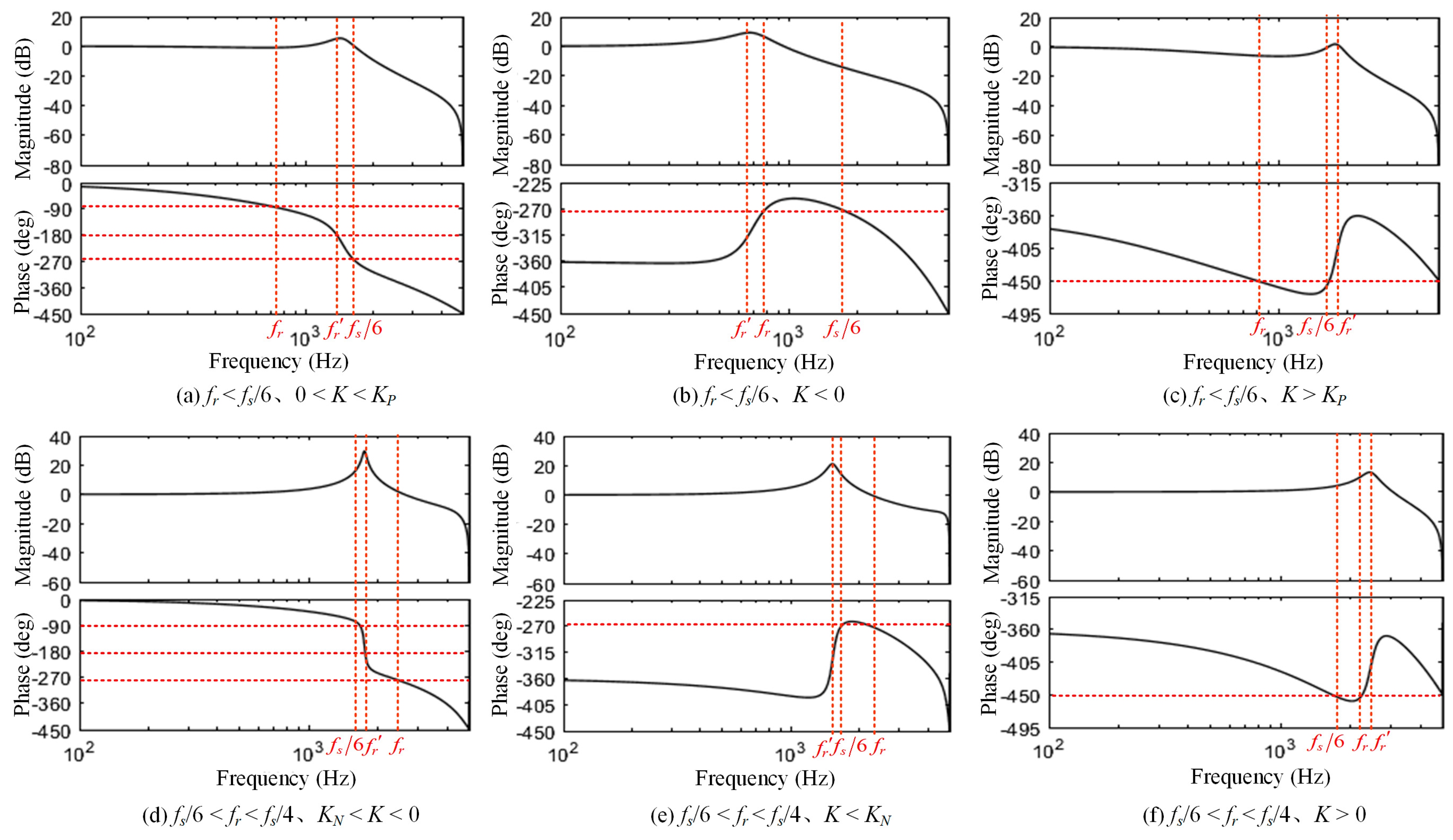
Figure 7 shows the Bode diagram for different values of the resonant frequency fr and the damping coefficient K. The following can be obtained:
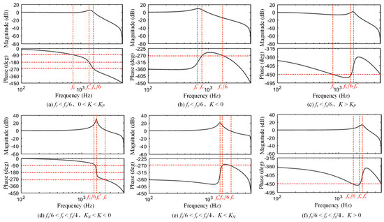
Figure 7.
Bode diagram for different values of fr and K.
① When fr < fs/6, 0 < K < KP, and P = 0, the −180° crossover frequency fr′ is within the range of (fr, fs/6). Adjusting Kpc can make the amplitude of Gso(z) at fr′ less than 0 dB. At this time, N = 0, Z = 0, and the closed-loop system is stable.
② When fr < fs/6, K < 0, and P = 2, the phase of Gso(z) will not cross −180°. At this time, N = 0, Z = 2, and the closed-loop system is unstable.
③ When fr < fs/6, K > KP, and P = 2, the phase of Gso(z) will not cross −180°. At this time, N = 0, Z = 2, and the closed-loop system is unstable.
④ When fs/6 < fr < fs/4, KN < K < 0, and P = 0, the −180° crossover frequency fr′ is within the range of (fs/6, fr). Adjusting Kpc can make the amplitude of Gso(z) at fr′ less than 0 dB. At this time, N = 0, Z = 0, and the closed-loop system is stable.
⑤ When fs/6 < fr < fs/4, K < KN, and P = 2, the phase of Gso(z) will not cross −180°. At this time, N = 0, Z = 2, and the closed-loop system is unstable.
⑥ When fs/6 < fr < fs/4, K > 0, and P = 2, the phase of Gso(z) will not cross −180°. At this time, N = 0, Z = 2, and the closed-loop system is unstable.
Based on the above analysis, only cases ① and ② can make the grid-connected CSI system stable. At this time, the phase of Gso(z) crosses −180° at fr′, and Gso(z) is a pure real number at fr′. Therefore, Gso(z) at fr′ can be derived as
The specific expressions of A and B are obtained as
Let the imaginary part of Gso(z) be 0; Gso(z) at fr′ can be derived as
where a = cos(ωrTs), b = Ksin(ωrTs)/ωrCf, c = (2a + 1)2 − 8b.
To make the closed-loop system stable, the amplitude of Gso(z) at fr′ needs to be less than 0 dB. At the same time, to enhance the anti-interference ability of the system, a 3 dB amplitude margin is usually left. Let 20 lg < −3 dB; Kpc can be derived as
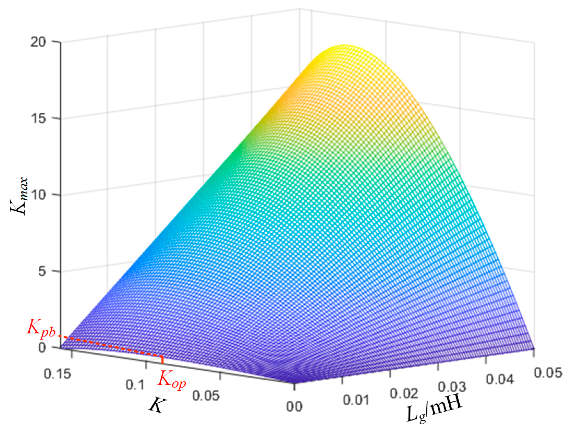
Figure 8 shows a three-dimensional graph of Kmax changing with the damping coefficient K and the equivalent inductance of the grid Lg when fr0 < fs/6, 0 < K < KP. It can be seen that when Lg = 0, that is, under a strong grid, there is an optimal damping coefficient Kop, corresponding to the maximum proportional gain Kpb, which maximizes the system loop gain and improves the system dynamic performance. As Lg increases, Kop and Kpb change, but under the same K, Kmax will increase with the increase in Lg. Therefore, the optimal control parameters designed in strong grids can ensure the stability of the grid current closed loop even if the influence of Lg on the CL filter is considered in weak grids.

Figure 8.
Three-dimensional graph of Kmax changing with K and Lg when fr0 < fs/6 and 0 < K < KP.
However, when fs/6 < fr0 < fs/4 and KN < K < 0, the increase in Lg will reduce fr, which may cause fr to cross the boundary of fs/6, and the stable range of K will change. When the control parameters remain unchanged, the system is prone to instability in weak grids. Therefore, when observing the grid voltage phase through the SMO, to ensure the robustness of the control parameters in weak grids, the system should use a CL filter with fr0 < fs/6.
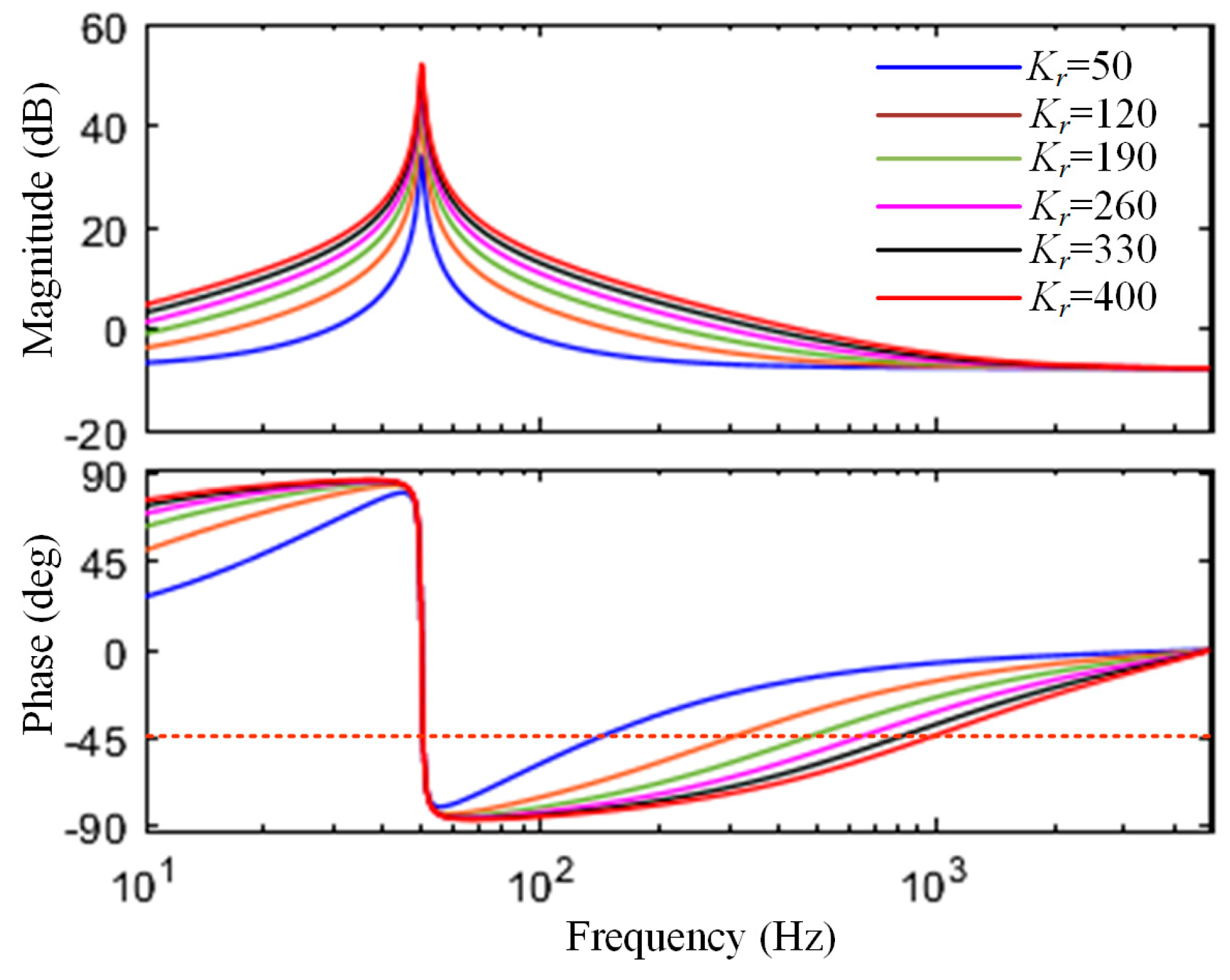
In addition, the value of the resonant gain Krc needs to be a compromise between the steady-state error and stability margin of the system. Figure 9 shows the Bode diagram corresponding to a different Krc when the proportional gain Kpc of the PR controller is the same. It can be seen that the larger the Krc, the higher the fundamental frequency amplitude and the smaller the steady-state error of the system. However, when the −45° corner frequency of the PR controller is much lower than the resonant frequency fr0 of the CL filter itself, it can not only reduce the impact of the phase offset of the PR controller on the system amplitude margin, but can also have a certain stability margin when the grid impedance causes fr to shift.

Figure 9.
Bode diagram of PR controller varying with Krc.
5. Experimental Results
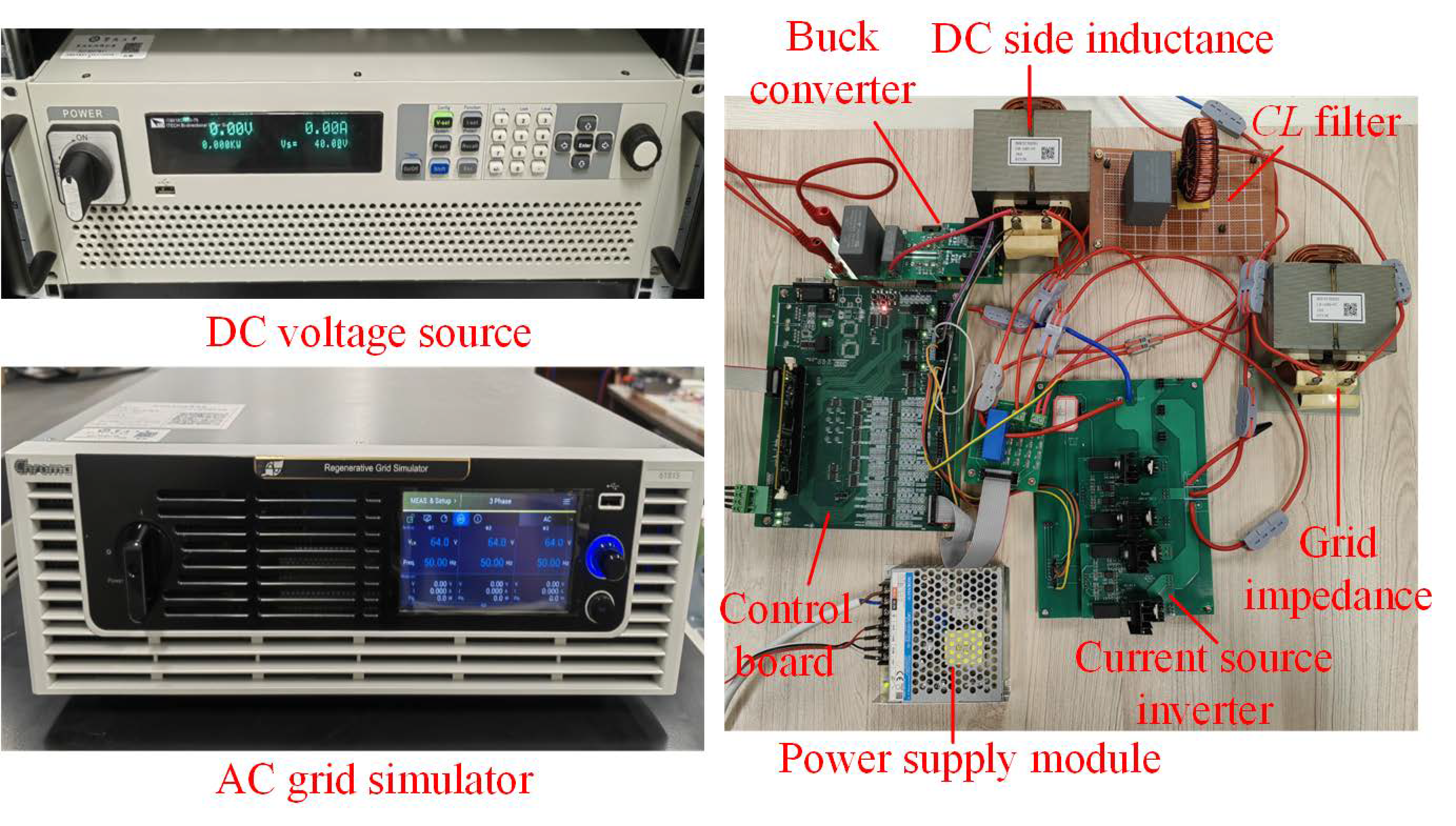
To verify the effectiveness of the proposed control strategy and parameter design method, an experimental platform for a grid-connected CSI was built, as shown in Figure 10, including the following: TMS320F28335 controller, power supply module, Buck circuit, CL filter, programmable AC power supply for simulating the power grid, and grid impedance. The Buck circuit is powered by a 40 V DC voltage source to control the DC bus current of the CSI to be constant. The main circuit parameters are shown in Table 2.

Figure 10.
Experiment setup of single-phase grid-connected CSI.
Table 2.
Main parameters of single-phase grid-connected CSI.
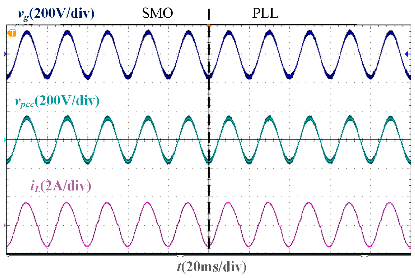
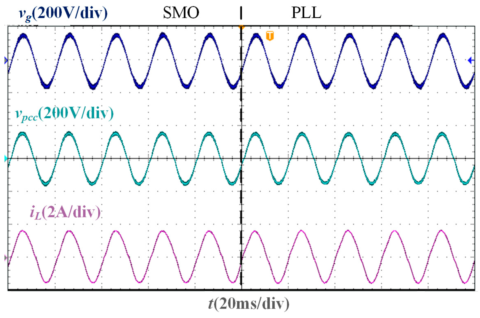
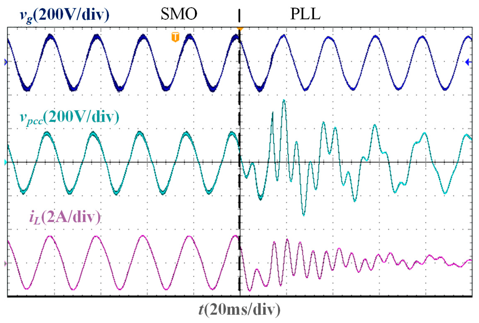
In the stability verification experiment based on the two phase-locking strategies of the SMO and PLL, the experimental waveforms under different Lg are shown in Figure 11, Figure 12, Figure 13 and Figure 14. It is worth noting that the parameters of the traditional PLL are designed based on the large-signal stability criterion and boundaries for grid voltage sags [30], and the design results are Kpp = 1.4 and Kip = 300. As the inductance value of Lg increases, the deviation between the PCC voltage phase and the grid voltage phase increases. When Lg = 0 mH, Lg = 10 mH, and Lg = 20 mH, the PLL-based current control system can still remain stable, and the grid current and PCC voltage maintain the same phase. However, when Lg = 37 mH, the current oscillates, and the system cannot be stable. Under different Lg, the grid current in the SMO-based current control system can accurately track the grid voltage phase and show a higher sinusoidal degree than that in the PLL-based current control system, and the SMO-based system remains stable.
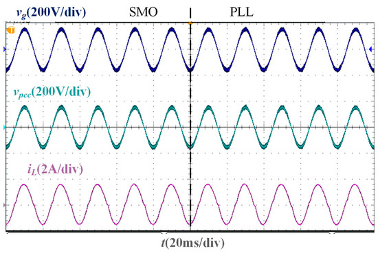
Figure 11.
Experimental waveforms of two phase-locking strategies when Lg = 0 mH.
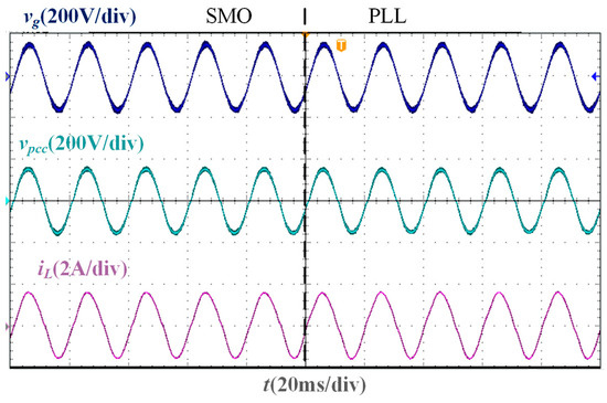
Figure 12.
Experimental waveforms of two phase-locking strategies when Lg = 10 mH.
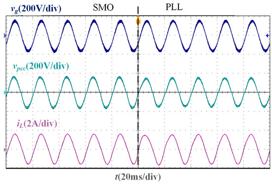
Figure 13.
Experimental waveforms of two phase-locking strategies when Lg = 20 mH.
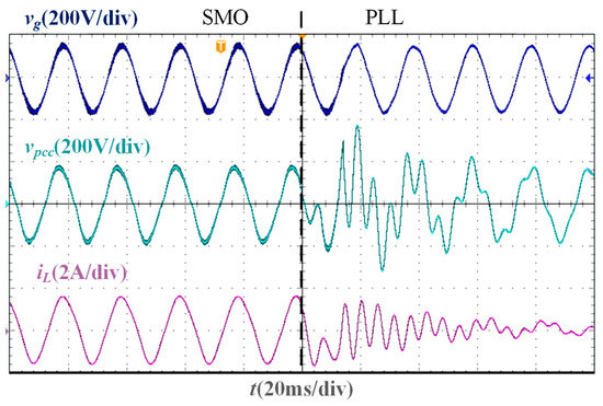
Figure 14.
Experimental waveforms of two phase-locking strategies when Lg = 37 mH.
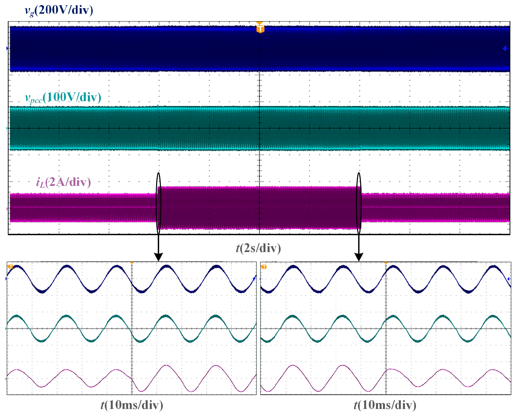
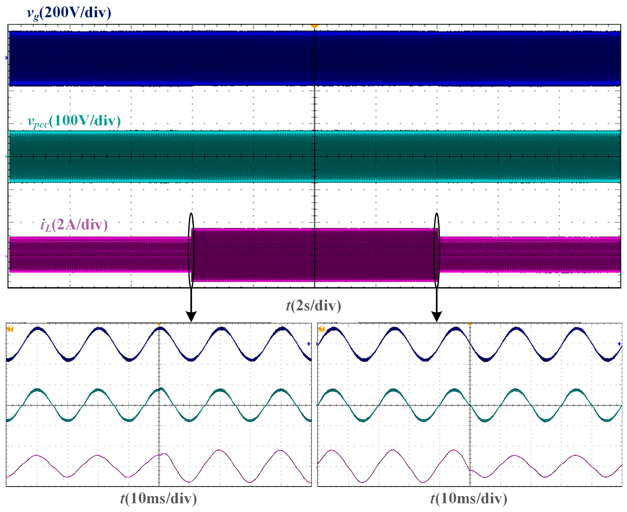
From the dynamic verification experiment based on the two phase-locking strategies of the SMO and PLL, the experimental waveforms under Lg = 10 mH are shown in Figure 15 and Figure 16. When the amplitude reference of the grid current undergoes a step change, the grid current of the SMO-based current control system can transition to a new steady state within one fundamental cycle, just like the grid current of the PLL-based current control system.
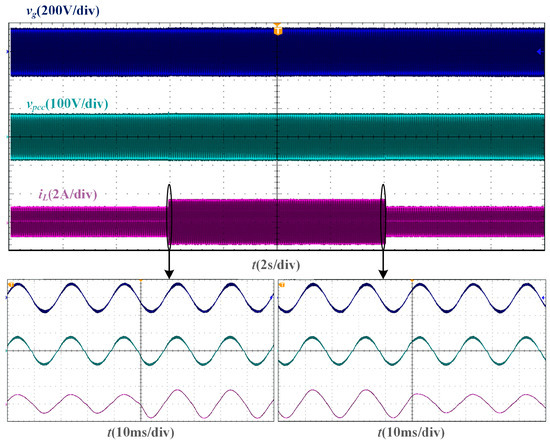
Figure 15.
Experimental waveforms of SMO-based current control system with a step change of current amplitude reference when Lg = 10 mH.
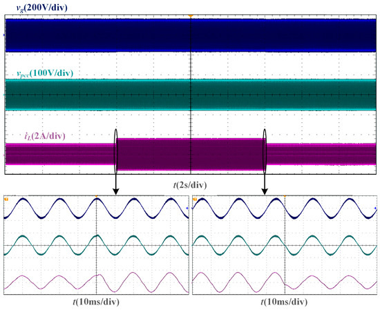
Figure 16.
Experimental waveforms of PLL-based current control system with a step change of current amplitude reference when Lg = 10 mH.
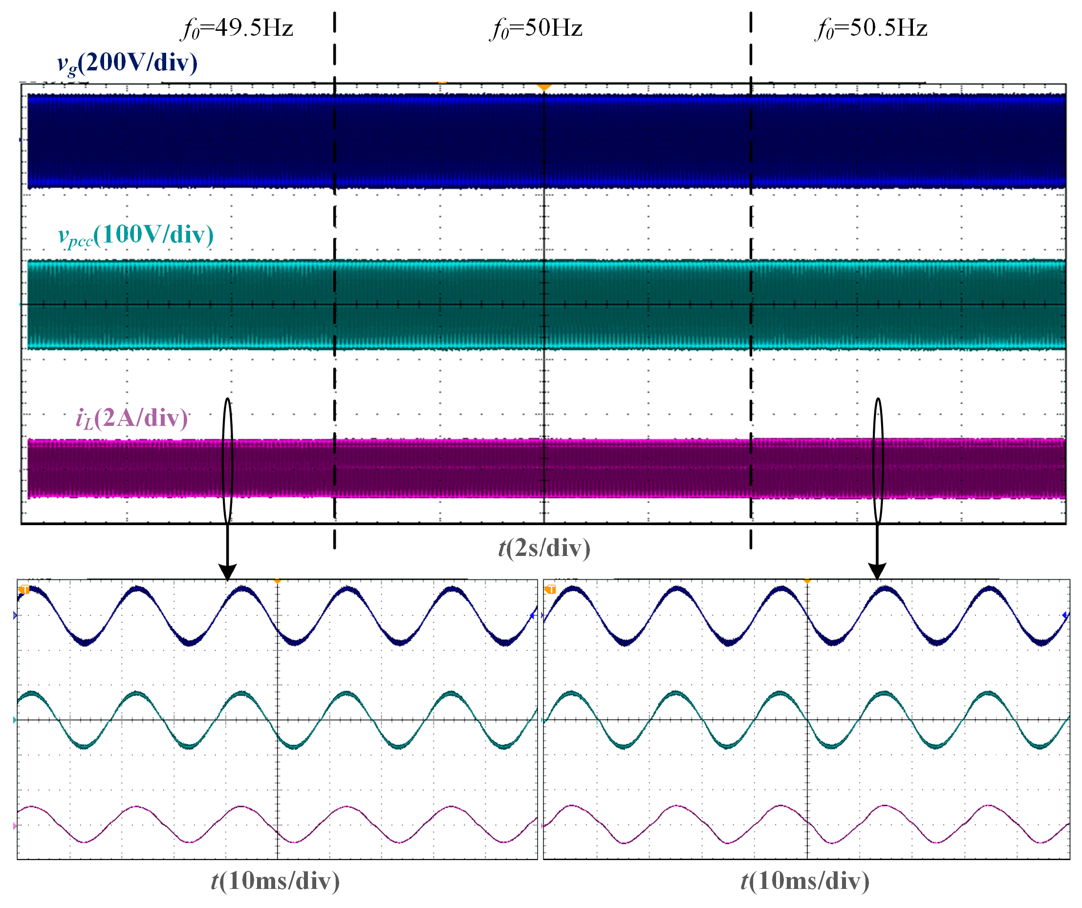
From the robustness verification experiment based on the SMO phase-locking strategy, the experimental waveform under Lg = 10 mH is shown in Figure 17. When the grid voltage frequency fluctuates by ±0.5 Hz, the SMO can still keep tracking the grid voltage phase, so that the grid current and the grid voltage can maintain the same phase.
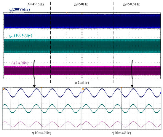
Figure 17.
Experimental waveforms of SMO-based current control system with a fluctuation of grid voltage frequency when Lg = 10 mH.
Based on the results of the above three experiments, the following conclusions can be drawn. The PLL-based phase-locking strategy has a significant problem of phase inconsistency between the PCC voltage and the grid voltage when the Lg is large, which makes the coupling degree between the PCC voltage, the grid impedance, and the current controller severe, and the system is prone to instability. However, on the premise that the SMO-based phase-locking strategy can maintain the same dynamic performance as the PLL-based phase-locking strategy, the former avoids the instability caused by coupling phenomena in weak grids by obtaining the grid voltage phase, and has the robustness to frequency changes of the grid voltage. In addition, under the SMO-based phase-locking strategy, the control parameters can be employed under different Lg without changing, which verifies the robustness of the parameters.
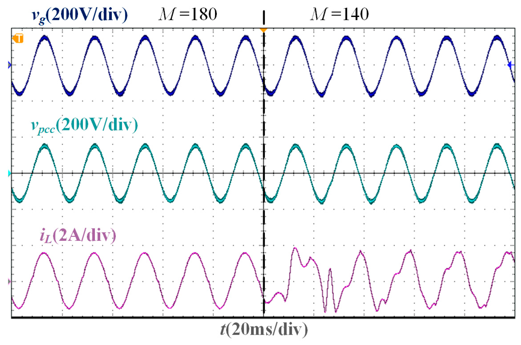
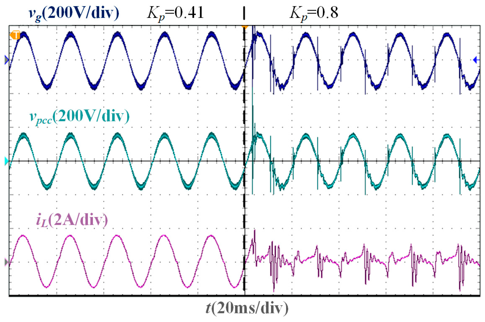
From the parameter comparison experiment, the experimental waveforms corresponding to M = 180 and M = 140 under Lg = 0 are shown in Figure 18. When M satisfies Equation (6), that is, M is greater than 155.54, the SMO converges, and the grid-connected CSI operates stably, but when M is less than 155.54, the SMO cannot converge and cannot accurately track the grid voltage phase. The experimental waveforms corresponding to Kpc = 0.41 and Kpc = 0.8 under Lg = 0 are shown in Figure 19. Under the optimal damping coefficient Kop = 0.09, the maximum proportional gain Kpb = 0.41, and the resonant gain Krc = 190, the grid current can accurately track the current command. However, when Kpc does not satisfy Equation (26), that is, Kpc is greater than 0.41, the system stability margin is low. When Kpc is slightly greater than 0.41, the current tends to diverge, and the system becomes unstable. The above phenomenon verifies the effectiveness of the parameter design results.
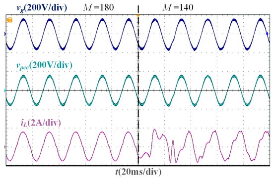
Figure 18.
Experimental waveforms of different sliding mode gains when Lg = 0 mH.
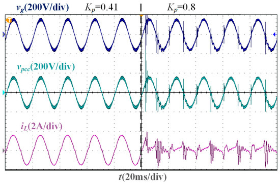
Figure 19.
Experimental waveforms of different proportional gains when Lg = 0 mH.
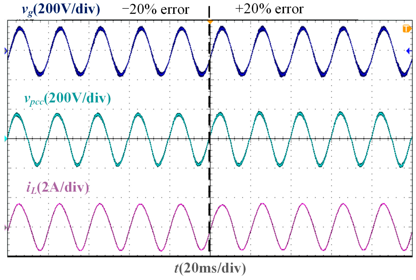
In the test experiment of grid impedance measurement deviation, the grid current can remain stable and accurately track the grid voltage phase when there is a ±20% error in the grid impedance measurement value, as shown in Figure 20. Therefore, the SMO-based current control system does not rely on the accuracy of the grid impedance measurement results.
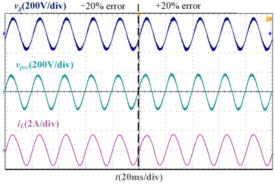
Figure 20.
Experimental waveform considering impedance measurement error when Lg = 37 mH.
6. Conclusions
To solve the problem of unstable operation of the grid-connected CSI in weak grids, this paper proposes an SMO for grid voltage phase detection, regards grid impedance as part of the CL filter, and further proposes a robust design method for grid current closed-loop parameters in weak grids. The main conclusions are as follows:
1. According to the circuit relationship between PCC voltage, grid current, and grid voltage, the proposed SMO can directly observe the grid voltage phase, so that the grid current can follow the grid voltage, and avoid the coupling problem between the PCC voltage phase detection effect of the PLL and the grid impedance. In addition, the observation result of the SMO does not depend on the accuracy of impedance measurement results, and the grid-connected CSI can operate stably even under ±20% measurement error.
2. Under the premise that the SMO can accurately obtain the grid voltage phase, the grid impedance can be regarded as a part of the CL filter, and a robust design method for the current controller parameters of the grid-connected CSI is further proposed to ensure that the CSI can operate stably under any grid impedance.
The proposed SMO-based phase-locking strategy and robust parameter design method are not only applicable to CSIs, but also to VSIs. The difference in the application is only the modeling of the control plant, but the analysis method is the same.
Author Contributions
Y.Z. wrote the original manuscript, designed the experiment, and carried out the test; H.D. offered guidance and project supervision; X.L. provided the necessary materials and equipment support; review and editing of the paper were mainly carried out by Y.G. All the authors discussed the results and commented on the manuscript. All authors have read and agreed to the published version of the manuscript.
Funding
This work was supported in part by the National Natural Science Foundation of China under Grant 52277182, and in part by the Major Talent Program of Guangdong Province (2019QN01L109).
Data Availability Statement
The original contributions presented in the study are included in the article; further inquiries can be directed to the corresponding author.
Conflicts of Interest
The authors declare that they have no known competing financial interests or personal relationships that could have appeared to influence the work reported in this paper.
References
- Guo, X.; Du, S.; Diao, N.; Hua, C.; Blaabjerg, F. Three-dimensional space vector modulation for four-leg current-source inverters. IEEE Trans. Power Electron. 2023, 38, 13122–13132. [Google Scholar] [CrossRef]
- Zhao, S.; Molina, J.M.; Silva, M.; Oliver, J.A.; Alou, P.; Torres, J.; Arévalo, F.; García, O.; Cobos, J.A. Design of energy control method for three-phase buck-type rectifier with very demanding load steps to achieve smooth input currents. IEEE Trans. Power Electron. 2016, 31, 3217–3226. [Google Scholar] [CrossRef]
- Xing, L.; Wei, Q.; Li, Y. A practical current source inverter-based high-power medium-voltage PV system. IEEE Trans. Power Electron. 2023, 38, 2617–2625. [Google Scholar] [CrossRef]
- Wei, Q.; Wu, B.; Xu, D.; Zargari, N.R. Power balancing investigation of grid-side series-connected current source inverters in wind conversion systems. IEEE Trans. Ind. Electron. 2017, 64, 9451–9460. [Google Scholar] [CrossRef]
- Li, M.; Zhang, X.; Guo, Z.; Pan, H.; Ma, M.; Zhao, W. Impedance adaptive dual-mode control of grid-connected inverters with large fluctuation of SCR and its stability analysis based on D-partition method. IEEE Trans. Power Electron. 2021, 36, 14420–14435. [Google Scholar] [CrossRef]
- Radwan, A.A.A.; Mohamed, Y.A.R. I Improved vector control strategy for current-source converters connected to very weak grids. IEEE Trans. Power Syst. 2016, 31, 3238–3248. [Google Scholar] [CrossRef]
- Azghandi, M.A.; Barakati, S.M.; Yazdani, A. Impedance-based stability analysis and design of a fractional-order active damper for grid-connected current-source inverters. IEEE Trans. Sustain. Energy 2021, 12, 599–611. [Google Scholar] [CrossRef]
- Xu, J.; Qian, Q.; Zhang, B.; Xie, S. Harmonics and stability analysis of single-phase grid-connected inverters in distributed power generation systems considering phase-locked loop impact. IEEE Trans. Sustain. Energy 2019, 10, 1470–1480. [Google Scholar] [CrossRef]
- Yu, J.; Lin, X.; Song, D.; Yu, R.; Li, Y.; Su, M. Harmonic instability and amplification for grid-connected inverter with voltage harmonics compensation considering phase-locked loop. IEEE J. Emerg. Sel. Top. Power Electron. 2020, 8, 3944–3959. [Google Scholar] [CrossRef]
- Li, Y.; Ding, L.; Li, Y. Isomorphic relationships between voltage-source and current-source converters. IEEE Trans. Power Electron. 2019, 34, 7131–7135. [Google Scholar] [CrossRef]
- Huang, L.; Wu, C.; Zhou, D.; Blaabjerg, F. A double-PLLs-based impedance reshaping method for extending stability range of grid-following inverter under weak grid. IEEE Trans. Power Electron. 2022, 37, 4091–4104. [Google Scholar] [CrossRef]
- Gong, H.; Wang, X.; Harnefors, L. Rethinking current controller design for PLL-synchronized VSCs in weak grids. IEEE Trans. Power Electron. 2022, 37, 1369–1381. [Google Scholar] [CrossRef]
- Xie, Z.; Chen, Y.; Wu, W.; Gong, W.; Zhou, L.; Zhou, X.; Guerrero, J. M Admittance modeling and stability analysis of grid-connected inverter with LADRC-PLL. IEEE Trans. Ind. Electron. 2021, 68, 12272–12284. [Google Scholar] [CrossRef]
- Alawasa, K.M.; Mohamed, Y.A.R.I.; Xu, W. Active mitigation of subsynchronous interactions between PWM voltage-source converters and power networks. IEEE Trans. Power Electron. 2014, 29, 121–134. [Google Scholar] [CrossRef]
- Maganti, S.; Padhy, N.P. Analysis and design of PLL less current control for weak grid-tied LCL-type voltage source converter. IEEE J. Emerg. Sel. Top. Power Electron. 2022, 10, 4026–4040. [Google Scholar] [CrossRef]
- Yang, D.; Wang, X.; Liu, F.; Xin, K.; Liu, Y.; Blaabjerg, F. Symmetrical PLL for SISO impedance modeling and enhanced stability in weak grids. IEEE Trans. Power Electron. 2020, 35, 1473–1483. [Google Scholar] [CrossRef]
- Lin, X.; Yu, J.; Yu, R.; Zhang, J.; Yan, Z.; Wen, H. Improving small-signal stability of grid-connected inverter under weak grid by decoupling phase-lock loop and grid impedance. IEEE Trans. Ind. Electron. 2022, 69, 7040–7053. [Google Scholar] [CrossRef]
- Lin, X.; Yu, R.; Yu, J.; Wen, H. Constant coupling effect-based PLL for synchronization stability enhancement of grid-connected converter under weak grids. IEEE Trans. Ind. Electron. 2023, 70, 11310–11323. [Google Scholar] [CrossRef]
- Berg, M.; Aapro, A.; Luhtala, R.; Messo, T. Small-signal analysis of photovoltaic inverter with impedance-compensated phase-locked loop in weak grid. IEEE Trans. Energy Convers. 2020, 35, 347–355. [Google Scholar] [CrossRef]
- Guo, L.; Li, Y.; Jin, N.; Dou, Z.; Wu, J. Sliding mode observer-based AC voltage sensorless model predictive control for grid-connected inverters. IET Power Electron. 2020, 13, 2077–2085. [Google Scholar] [CrossRef]
- Yang, H.; Zhang, Y.; Liang, J.; Gao, J.; Walker, P.D.; Zhang, N. Sliding-mode observer based voltage-sensorless model predictive power control of PWM rectifier under unbalanced grid conditions. IEEE Trans. Ind. Electron. 2018, 65, 5550–5560. [Google Scholar] [CrossRef]
- Wang, G.; Du, X.; Shi, Y.; Yang, Y.; Sun, P.; Li, G. Effects on oscillation mechanism and design of grid-voltage feedforward in grid-tied converter under weak grid. IET Power Electron. 2019, 12, 1094–1101. [Google Scholar] [CrossRef]
- Wang, X.; Qin, K.; Ruan, X.; Pan, D.; He, Y.; Liu, F. A robust grid-voltage feedforward scheme to improve adaptability of grid-connected inverter to weak grid condition. IEEE Trans. Power Electron. 2021, 36, 2384–2395. [Google Scholar] [CrossRef]
- Chen, X.; Zhang, Y.; Wang, S.; Chen, J.; Gong, C. Impedance-phased dynamic control method for grid-connected inverters in a weak grid. IEEE Trans. Power Electron. 2017, 32, 274–283. [Google Scholar] [CrossRef]
- Zhu, D.; Zhou, S.; Zou, X.; Kang, Y.; Zou, K. Small-signal disturbance compensation control for LCL-type grid-connected converter in weak grid. IEEE Trans. Ind. Appl. 2020, 56, 2852–2861. [Google Scholar] [CrossRef]
- Guo, B.; Zhang, X.; Ma, H.; Yang, Y.; Wang, X.; Tian, Q.; Jin, S. A series impedance reshaping control method considering PLL dynamics for grid-connected inverters under weak grid conditions. IEEE Trans. Ind. Electron. 2024, 71, 4896–4910. [Google Scholar] [CrossRef]
- Mohamadian, S.; Pairo, H.; Ghasemian, A. A straightforward quadrature signal generator for single-phase SOGI-PLL with low susceptibility to grid harmonics. IEEE Trans. Ind. Electron. 2021, 69, 6997–7007. [Google Scholar] [CrossRef]
- Liu, Z.; Liu, J.; Liu, Z. Analysis, design, and implementation of impulse-injection-based online grid impedance identification with grid-tied converters. IEEE Trans. Power Electron. 2020, 35, 12959–12976. [Google Scholar] [CrossRef]
- Wang, J.; Chen, L.; Liu, Z.; Zhang, Z.; Zhang, X. Optimized parameter design of the dual-loop control for grid-forming VSCs with LC filters. IEEE Trans. Ind. Appl. 2022, 58, 820–829. [Google Scholar] [CrossRef]
- Xu, J.; Hu, Y.; Qian, H.; Xie, S. Delay-based phase-locked loop parameters design based on stability region of grid-connected single-phase inverter under grid voltage sags. IEEE Trans. Ind. Electron. 2021, 69, 11324–11334. [Google Scholar] [CrossRef]

Disclaimer/Publisher’s Note: The statements, opinions and data contained in all publications are solely those of the individual author(s) and contributor(s) and not of MDPI and/or the editor(s). MDPI and/or the editor(s) disclaim responsibility for any injury to people or property resulting from any ideas, methods, instructions or products referred to in the content. |
© 2024 by the authors. Licensee MDPI, Basel, Switzerland. This article is an open access article distributed under the terms and conditions of the Creative Commons Attribution (CC BY) license (https://creativecommons.org/licenses/by/4.0/).