Review

Hydrogen Refueling Stations: A Review of the Technology Involved from Key Energy Consumption Processes to Related Energy Management Strategies

by
Rafael Pereira
1,2,*,
Vitor Monteiro
1,
Joao L. Afonso
1 and
Joni Teixeira
2
1
Centro ALGORITMI/LASI, University of Minho, 4800-058 Guimarães, Portugal
2
Petrotec, 4805-661 Guimarães, Portugal
*
Author to whom correspondence should be addressed.
Energies 2024, 17(19), 4906; https://doi.org/10.3390/en17194906
Submission received: 15 July 2024 / Revised: 12 September 2024 / Accepted: 28 September 2024 / Published: 30 September 2024
(This article belongs to the Section A5: Hydrogen Energy)

Abstract

:
Over the last few years, hydrogen has emerged as a promising solution for problems related to energy sources and pollution concerns. The integration of hydrogen in the transport sector is one of the possible various applications and involves the implementation of hydrogen refueling stations (HRSs). A key obstacle for HRS deployment, in addition to the need for well-developed technologies, is the economic factor since these infrastructures require high capital investments costs and are largely dependent on annual operating costs. In this study, we review hydrogen’s application as a fuel, summarizing the principal systems involved in HRS, from production to the final refueling stage. In addition, we also analyze the main equipment involved in the production, compression and storage processes of hydrogen. The current work also highlights the main refueling processes that impact energy consumption and the methodologies presented in the literature for energy management strategies in HRSs. With the aim of reducing energy costs due to processes that require high energy consumption, most energy management strategies are based on the use of renewable energy sources, in addition to the use of the power grid.

1. Introduction

The transport sector is highly regarded as a considerable and growing source of air pollution across the world [1]. This sector consumes the largest amount of fossil fuels worldwide, with a direct impact on carbon dioxide (CO2) emissions [2]. In 2022, this sector accounted for more than 20% of global CO2 emissions [3]. CO2 emissions have significantly increased each year, reaching over 37 gigatons of CO2 in 2023, compared to less than 5 gigatons in 1940 [4]. To reverse this negative trend, the European Union signed the Paris Agreement and agreed on the aim of carbon neutrality by 2050 [5]. Due to growing concern about the high values of pollution as well as the negative repercussions of the excessive use of fossil fuels, new alternative solutions focused on sustainable mobility were developed, with an increase in the development of environmentally friendly vehicle technologies, such as electric and hydrogen vehicles [6], namely battery electric vehicles (BEVs) and fuel cell electric vehicles (FCEVs). FCEVs can use hydrogen as fuel and are considered one of the most prominent options, with a major role in the future of transport [2]. Compared to BEVs, the main advantages of FCEVs are the higher travel range and the quick refueling time, although they face challenges due to the cost and durability of the technology, security issues and the lack of hydrogen infrastructure [7]. By overcoming these barriers, the successful deployment of fuel cell technology could be a key element to reach the European Union’s CO2 emissions goal by 2050.
The transition to hydrogen-based mobility demands the further infrastructure development that must be able to meet the demand for hydrogen [8]. Hydrogen refueling stations (HRSs) are an example of this infrastructure, being intended for the refueling of hydrogen vehicles, such as FCEVs. As far as the presence of HRSs in the world is concerned, several countries have already implemented them, some of which are open to public supply, while others are dedicated to the private supply of a certain number of vehicles. Between 2021 and 2023, there was a significant increase of 60% in the number of HRS installations, with over 1100 operational HRSs being reached globally by 2030 [9]. Within this number, the Asia-Pacific region accounts for more than 780 HRSs, followed by Europe, with a number close to 250 installations, and the American continent with 80 infrastructures established.
Aligned with the relevance of HRSs, this paper presents a review on the technology involved, from the main energy consumption processes to the related energy management strategies, where the main contributions can be highlighted as follows: (i) a comprehensive literature review is conducted about the main processes concerning HRS, with a special focus on the technologies utilized, the processes that impact the energy consumption required for HRS operation and the related operation strategies; (ii) it fills the gap in the current literature focusing on an ample review, as presented in this paper, since the presentation of some of the covered topics is dispersed in various articles and without the necessary contextualization of combined topics; (iii) a review is undertaken on the approaches of the operation methodologies for the energy management proposed for HRSs, since there are no studies that summarize them and highlights the methods on which they are based in the literature; (iv) description of the types of gaseous hydrogen storage tanks and presentation of advantages and disadvantages of each type of electrolyzer and compressors type; (v) the research carried out and the covered topics are aligned with an industrial perspective framed in a cooperative project related with an HRS.
Following the Introduction, this review presents the following: hydrogen as an alternative fuel in Section 2; hydrogen production in an HRS in Section 3; the distinct types of hydrogen storage contextualized in an HRS in Section 4; the technologies of compression in an HRS in Section 5; hydrogen refueling process specifications in Section 6; the energy consumption in an HRS in Section 7; and, finally, the main conclusions are in Section 8.

2. Hydrogen as an Alternative Fuel

One of the essential elements in the operation of HRSs is the fuel to be used to refuel vehicles, which is hydrogen. In recent years, hydrogen has gained importance on the world stage, with increased interest in its use as a potential candidate to replace conventional fossil fuels [10]. However, despite its recognition as an ideal and emerging energy carrier [11,12], hydrogen has some particularities of its own that need to be considered in the applications in which it is involved.
Hydrogen is the most abundant chemical element in the universe, forming numerous compounds [13]. In its pure state, hydrogen is a flammable, invisible, colorless, and odorless gas in the form of a diatomic molecule, made up of two hydrogen atoms. However, despite being simple and abundant, hydrogen is not naturally present in the form of a gas on Earth [14]. Most of the hydrogen present on the planet is, in fact, a compound of oxygen, under the form of water [15], while some hydrogen can also be found in various organic compounds, namely hydrocarbons [14].
Under normal conditions of pressure and temperature (0 °C and 1 atm), this chemical element is in the gaseous state, and it has a density of 0.0899 g/L, which is 14.4-times lighter than air [16]. Of all substances, hydrogen has the particularity of presenting the second lowest boiling point and melting point [17]. At ambient pressure, the boiling point and melting point are −253 °C and −259 °C, respectively [17]. In its liquid state, hydrogen has a density of 70.8 g/L [15]. In terms of its mass, hydrogen has a higher energy density than most of the fuels used [18]; however, in terms of volume, hydrogen in its gaseous state has a very low volumetric energy density in comparison to fossil fuels, meaning that a high volume of hydrogen is needed to store the equivalent quantity of energy [19]. Hydrogen also has flammability limits, which are between 4% and 75%, considering the volume percentage of air, and if the hydrogen concentration rises above the lower flammability limit, a minimal quantity of energy could ignite hydrogen because of hydrogen’s low ignition energy (0.02 mJ) [20].

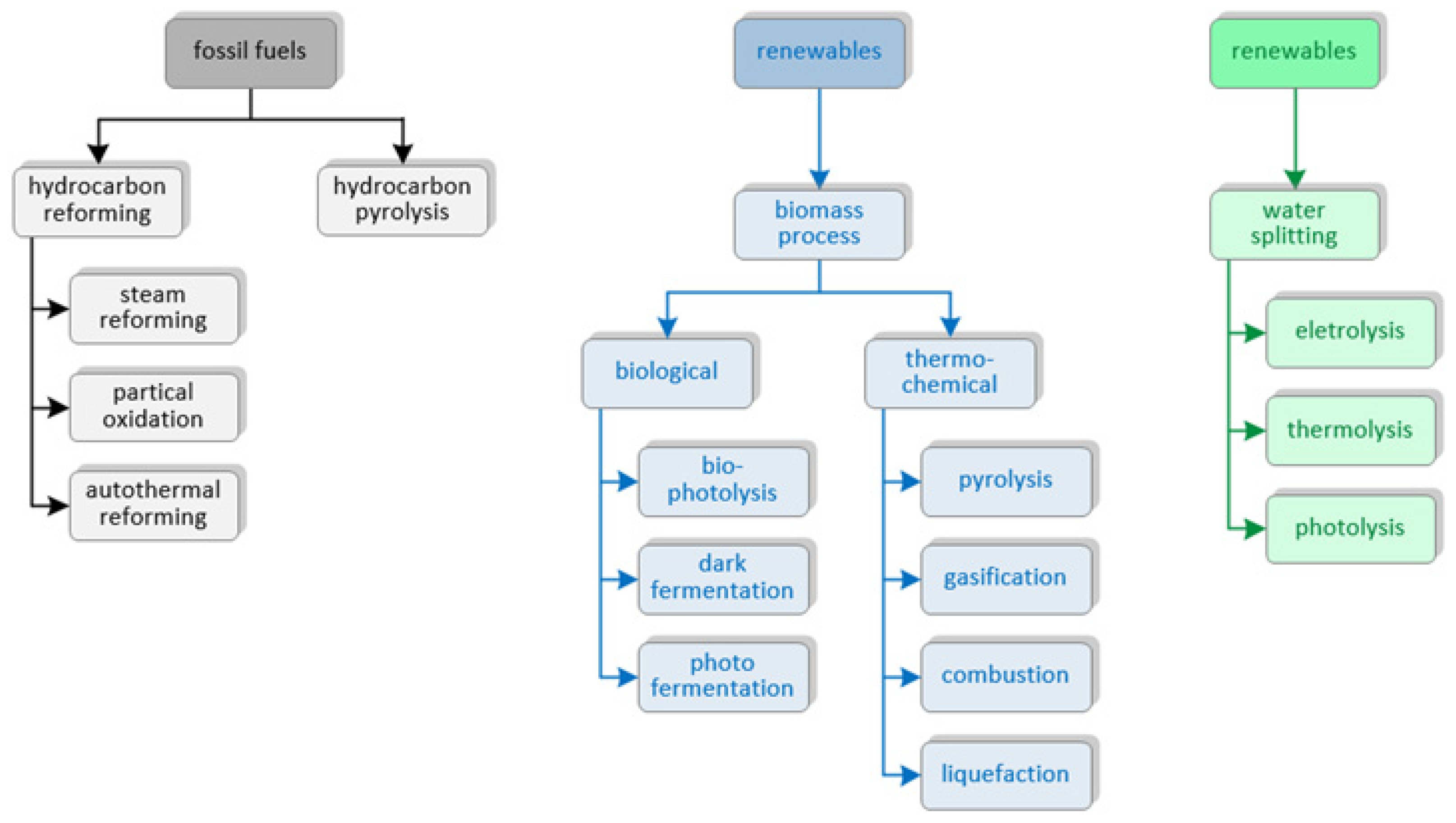
3. Hydrogen Production in a Hydrogen Refueling Station

Hydrogen can be produced from various sources, using diverse methods, and transported to HRSs or, as an alternative, it can be produced at an HRS [21]. Depending on where the hydrogen is produced, an HRS can be classified into two types [22]. When an HRS has the equipment to produce hydrogen, the production of hydrogen takes place on site and the stations are called on-site HRSs, whereas if the hydrogen is produced elsewhere and then transported to the HRS, these stations are defined as off-site HRSs [23].
There are two categories of possible production methods, in which hydrogen can be produced using non-renewable energy sources, such as fossil fuels, or renewable energy sources [24]. For fossil fuels, production using hydrocarbons stands out, such as natural gas, coal and oil. Production by steam methane reforming, where the natural gas is converted into hydrogen [25], is the most widely used for the world’s hydrogen supply [26]. Regarding the production of hydrogen from renewable energy sources, it can use biomass, with decomposition and oxidation actions, or it can use solar or wind energy, through the decomposition of water. Figure 1 summarizes the categories mentioned for the various hydrogen production methods.
The concept of green hydrogen is associated with the hydrogen production process that involves the use of energy from renewable energy sources, with water electrolysis being a common method in this type of production. Electrolysis refers to a process in which a non-spontaneous chemical reaction is caused by the transmission of an electric current through an electrolyte [27]. The process of water electrolysis is carried out by adding an electrolyte to the water, which makes it conductive and allows for a direct current to pass through it [28], promoting the occurrence of the chemical reactions inherent to the process. In this process, the chemical reactions result in the breakdown of the water molecule (H2O), which splits into oxygen and hydrogen, both in the gaseous state, through the production of an electrical potential difference between two electrodes in an electrolyte [29]. The electrolyzer consists of two electrodes: the cathode, representing the negative pole where the reduction reaction takes place, and the anode, representing the positive pole where the oxidation reaction takes place. There is a separator between these electrodes to ensure the separation of the resulting products, and when electricity is applied, with a potential difference that is sufficient to break down the water molecule, oxygen is produced at the anode and hydrogen at the cathode [30]. If renewable energy sources are used as a source of electricity, the water electrolysis process allows for hydrogen production with zero CO2 emissions [31].
The electrolyzer is the component responsible for the local hydrogen production in an HRS, being the equipment that carries out the process of water electrolysis, as illustrated in Figure 2. Although electrolyzers are a possible sustainable solution, they are a technology that still presents various economic obstacles, with the water electrolysis process accounting for only 4% of the world’s hydrogen gas volume [32].
There are several types of electrolyzers, and their distinction is related to the method of water electrolysis, namely the type of electrolyte used, the operating conditions and the respective ionic agents [33]. Electrolyzers can be classified into four types: alkaline water electrolyzer (AWE); proton membrane electrolyzer (PEM); alkaline anion exchange membrane electrolyzer (AAEM); and solid oxide electrolyzer (SOE). Since these types of electrolyzers present distinct characteristics, which can be useful according to the final application, Table 1 presents an intuitive summary regarding the advantages and disadvantages of each type of electrolyzer.
The AWE’s electrolyte is an aqueous alkaline solution containing 20% to 40% of potassium hydroxide (KOH) or sodium hydroxide (NaOH) [34]. The electrodes are separated by a diaphragm that allows negative hydroxide ions (OH) to pass through to the anode and separates the hydrogen and oxygen, resulting in a hydrogen purity of between 99.5% and 99.9% [32]. PEM uses a solid polymer electrolyte and has an electrolytic membrane to separate the reactions at the cathode and anode, allowing only positive hydrogen ions (H+) to pass through to the cathode, resulting in a hydrogen purity of 99.9% [33]. AAEM is a combination of AWE and PEM, presenting the advantages of both types [34] and a hydrogen purity of 99.9% [33]. This type has a low-concentration aqueous alkaline solution as its electrolyte and, like PEM, uses an electrolytic membrane, which, however, only allows the passage of negative hydroxide ions (OH) to be transported through the membrane to the cathode to produce hydrogen [32]. The operating temperatures for AWE, PEM and AAEM are lower than 100 °C, whereas SOE stands out for operating at very high temperatures, namely above 650 °C [36]. This type of electrolyzer uses a solid electrolyte made up of ceramic materials that enable the conduction of oxide ions (O2) [33], with a hydrogen purity of 99.9% [29], and although the electrolysis process takes place at high temperatures, the energy required is lower when compared to other methods [32].
For low-temperature water electrolyzers, including AWE, PEM and AAEM, water quality is also a pertinent parameter because water impurities can impact the performance and the lifetime of these types of electrolyzers [37]. Regardless of the amount of water needed to operate the electrolysis process, the electrolyzer requires high-purity water. The accumulation of ions can lead to corrosion of the electrolyzer components, with cationic impurities being the most problematic impurity for the PEM, while for the AAEM and the AWE, anionic impurities represent a direct threat [37]. The further development of electrolyzers with impurity tolerance could contribute to a reduction in capital and maintenance costs, as well as increasing their durability [38].

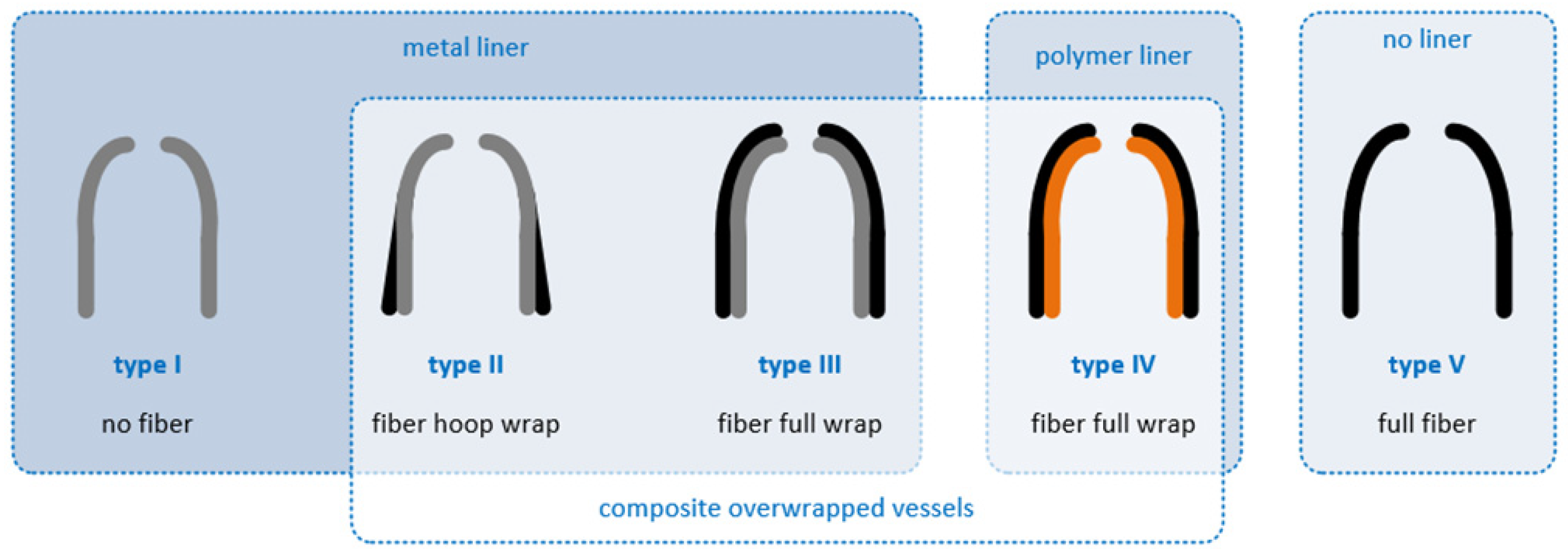
4. Types of Hydrogen Storage in Hydrogen Refueling Stations

Hydrogen storage is an essential factor in HRSs, and the storage of this fuel is considered to be at least as important as its production [35,39]. The cost of hydrogen storage is a fundamental challenge that needs to be faced so that hydrogen can become a competitive and viable energy vector [19]. For HRSs, this is a considerable cost, representing more than 20% of the capital expenditure (CAPEX) [40]. Hydrogen storage can be divided according to its physical states, and, in HRSs, hydrogen can be supplied as a gas or as a liquid [41]. Based on these differences, HRSs can be categorized into gaseous hydrogen stations or liquid hydrogen stations [42], and, therefore, gaseous and liquid storage is the main type of storage used.
Liquid hydrogen storage involves cryogenic tanks that maintain hydrogen in its liquid state at cryogenic temperatures [43]. Since hydrogen has a much higher density in the liquid state than the density in the gaseous state, it results in a greater mass and, consequently, a greater amount of stored hydrogen. For this reason, hydrogen storage in the liquid state can contain a greater amount of stored hydrogen compared to the gaseous state, thus providing the advantage of a high volumetric storage density [44]. However, the fact that hydrogen is liquid at a very negative temperature, with a boiling temperature of −253 °C, implies that the liquefaction process must involve high investment costs, as well as the consumption of large amounts of energy to keep the hydrogen in its liquid state [35,45]. The high energy required and the high hydrogen boil-off losses are some of the crucial challenges for the successful deployment of this type of storage [44]. As this type of storage still presents complex processes and challenges to overcome, after the hydrogen is supplied to HRSs in a liquid state, it undergoes a vaporization process and is converted into its gaseous form through a heat exchanger so it can then be compressed to a specified pressure [41].
The storage of hydrogen in the gaseous state is the most mature technology, and this type of storage is the most widely used method [46,47]. This storage method uses high-pressure compressed gas tanks, which are also called cylinders or vessels. The need to use high pressures is because hydrogen needs to be stored in significant quantities to occupy a smaller volume, since hydrogen has a low density in its gaseous state. Higher storage pressure increases the energy content per unit volume, resulting in a higher volumetric energy density [48]. Therefore, the compatibility of materials is a factor to be taken into consideration to guarantee safe and efficient storage, and storage equipment needs to be robust and made of materials resistant to high pressures [49]. These storage tanks can also be categorized into five types [50], according to the types of materials used in their manufacture. These types are described in Table 2 and are illustrated in Figure 3.
Type I is an all-metal gas tank and, of all the existent types, is the cheapest segment, the easiest to fabricate and, due to the high density of metal materials, the heaviest [51]. Type II differs from Type I by being wrapped in carbon fiber and allows for a higher working pressure of around 300 bar, while Type I has a working pressure of around 200 bar [51]. Type III and Type IV are used as solutions for vehicle applications, with a lower weight and higher working pressure compared to the types described previously. Type III uses a metal liner, while Type IV uses a polymer liner, allowing for a reduction in weight and an improvement in storage density [52]. Type IV is the most used type due to its high capacity and lightweight design but is the most expensive [19]. Type V is fully made of composite materials, such as carbon fiber or fiberglass [50] and has a great potential for raising the density of hydrogen storage; however, it is still in the development stage, with some constraints that need to be addressed to ensure that they can be developed and offer a viable alternative to Type IV [53].

5. Compression in Hydrogen Refueling Stations

As mentioned in Section 4, despite the distinct existing forms of hydrogen storage, the refueling process that takes place in HRSs is with the use of hydrogen in its gaseous state. The supply of hydrogen in the gaseous state can take place through local production at an HRS, using electrolyzers, or it can be undertaken through different transportation methods, usually via tube trailers with pressures of over 180 bar [41]. If the hydrogen is produced by electrolyzers, the pressure of the hydrogen produced is considerably lower, ranging from 30 bar to 40 bar [40], depending on the type of electrolyzer. To be able to fuel the different types of vehicles, the pressure of the hydrogen needs to be increased, since the maximum tank pressure of a light vehicle is 700 bar, while the maximum tank pressure of a heavy vehicle is 350 bar. The compressor is the equipment responsible for being able to raise the hydrogen pressure to the required storage pressure, providing a higher output pressure compared to the input pressure, namely at values above 200 bar [40].

5.1. Types of Compressors

Compressors can be classified into two categories: mechanical compressors and non-mechanical compressors. The mechanical compressors use moving parts to compress hydrogen, in which gaseous hydrogen is squeezed into smaller compartments using mechanical energy, thus obtaining higher pressures [54]. On the other hand, the non-mechanical compressors are characterized by the absence of moving mechanical parts [55], which is an advantage over mechanical compressors since it is possible to reduce installation and maintenance costs [56].
In an HRS, the most used type of compressor is mechanical compressors, namely piston compressors and diaphragm compressors [40,48]. Diaphragm compressors are distinguished by the fact that there is no direct contact between the piston and the compressed gas, with the piston’s reciprocating movement being transmitted via a hydraulic fluid to a diaphragm [57]. As the diaphragm is responsible for isolating the compressed gas and separating the two fluids, these compressors are ideal for applications that require high gas purity, and the fact that these compressors have several pressure stages and can achieve high pressures makes them commonly used for compressing hydrogen in HRSs [48]. Another solution for mechanical compressors is ionic liquid compressors, which are designed to improve compression efficiency [56] and, therefore, have the most potential in HRSs [58]. Non-mechanical compressors are subdivided into electrochemical compressors, in which compression is carried out through electrochemical reactions, and metal hydride compressors, in which compression is performed using thermal processes that exploit the properties of certain metals, alloys and intermetallic compounds to absorb hydrogen [56]. Table 3 presents the advantages and disadvantages of each type of compressor described above for HRSs.

5.2. Compression and Storage Systems

In HRSs, different approaches and systems for storing and compressing hydrogen can be presented, with two types of schemes standing out: cascade refueling and direct refueling [41].
The purpose of the cascade-based refueling system is to store hydrogen at certain pressure levels, decreasing the average pressure variation during refueling [59]. In this method, there are usually three high-pressure tanks, placed between the compressor area and the dispenser, and the compression is carried out through three pressure levels [60]. This number of compression levels corresponds to the three pressure levels possible, with one tank representing the lowest pressure (low-pressure tank), intermediate pressure (medium-pressure tank) and highest pressure (high-pressure tank) [61]. During the refueling process, hydrogen begins to flow from a low-pressure-level tank before the pressure reaches a specific limit through a reduction valve, located downstream of the storage tank [59]. After that, the refueling system switches to the next pressure-level storage tank, and when the pressure in the medium-pressure tank is depleted to a set level, the high-pressure tank is used until the vehicle tank is completely refueled [62]. The compressor turns on immediately when the storage tanks are emptying to fill the high-pressure tank and, subsequently, the medium-pressure tank and the low-pressure tank [63].
The direct refueling method is a more simplistic approach with only a single-tank storage unit, in which refueling is regulated by the pressure difference between the high-pressure storage tank and the vehicle storage tank [59]. In this method, a storage tank is presented at a pressure of between 350 bar and 500 bar, using just one compressor to increase the pressure to the desired refueling pressure [41].
As part of the two aforementioned systems described, the cascade system is the most adopted configuration for HRSs, with the relevant advantages of allowing for reduced energy consumption and costs [59,62]. However, in these three high-pressure tanks, the volume ratio of each stage does not reach the universally recognized ideal configuration [42], and so the pressures are usually chosen according to the price and physical limitations of the storage tanks [64].

6. Refueling Process Specifications

Refueling vehicles in an HRS requires compliance with safety conditions and the fulfillment of certain requirements established in the existing refueling protocols. When it comes to refueling hydrogen in light and heavy vehicles, there is a technical standard that defines the refueling specifications, the “SAE J2601”. The aim of this standard, developed by the Society of Automotive Engineers (SAE), is to guarantee the transfer of hydrogen fuel safely and efficiently from the dispenser to the vehicle and to provide compatibility among vehicles and HRSs [65]. For this purpose, performance requirements and safety limits are defined, especially limits related to the hydrogen pre-cooling temperature, the pressure at the dispenser and the maximum permitted flow rate. Within these parameters, the hydrogen minimum temperature is −40 °C, the maximum temperature of the vehicle hydrogen is restricted to 85 °C, the mass filling rate of hydrogen cannot exceed 60 g/s and the pressure of the high-pressure hydrogen storage tank needs to be lower than 125% of the nominal working pressure [66]. The dispenser unit is the equipment responsible for refueling the vehicle in accordance with the hydrogen pre-cooling temperatures defined in the “SAE J2601” refueling protocol [60].
According to the “SAE J2601” standard, HRSs can adopt two methods for the refueling process: “Table-based” and “MC Formula” [67]. The “MC Formula” method is a formula-based approach that uses a dynamic pressure ramp rate (PRR) calculated during refueling, with the target end-of-fill pressure being obtained continuously [68]. The calculation is carried out using a set of empirical formulas and coefficients, depending on parameters, such as the vehicle initial tank pressure, tank capacity, ambient temperature and the temperature of the pre-cooled fuel leaving the dispenser. Adaptive control is used to carry out this calculation over a range of pre-cooling temperatures from −40 °C to −17.5 °C [69]. The “Table-based” method refers to a look-up table approach that uses a fixed PRR, providing a fixed end-of-fill pressure target [68]. This approach is based on tabulated values, presented in a varied set of individual tables that are determined depending on the vehicle tank storage capacity (2–4 kg, 4–7 kg and 7–10 kg), the type of dispenser interface (with or without communication of information on the temperature and pressure parameters of the vehicle tank), the delivered pressure classes (350 bar and 700 bar) and the different pre-cooling temperature categories (−40 °C, −30 °C or −20 °C) [69]. In this method, the ambient pressure defines the speed of refueling, particularly the average pressure ramp rate, and the combination of ambient temperature and initial pressure specifies the desired pressure to be reached when the refueling is completed [69,70].
The temperature is a fundamental factor to be taken into account since excessive temperatures can negatively influence the tank material’s mechanical properties and the filling efficiency [66]. To shorten refueling times, high pressure differences are required between the vehicle tank and the tanks installed in the HRS, so heat is generated when refueling the vehicle as the gas expands due to the hydrogen-negative Joule–Thomson coefficient [71]. During the refueling process, the Joule–Thomson coefficient effect happens when gaseous hydrogen at a high pressure flows through the valve assembly, resulting in an increase in the hydrogen temperature [72]. Therefore, when the vehicle needs to be refueled, the high-pressure storage system in the HRS is cooled to a set pre-cooling temperature, assuring that the hydrogen temperature does not exceed 85 °C, by a pre-cooling unit, also known as a chiller.

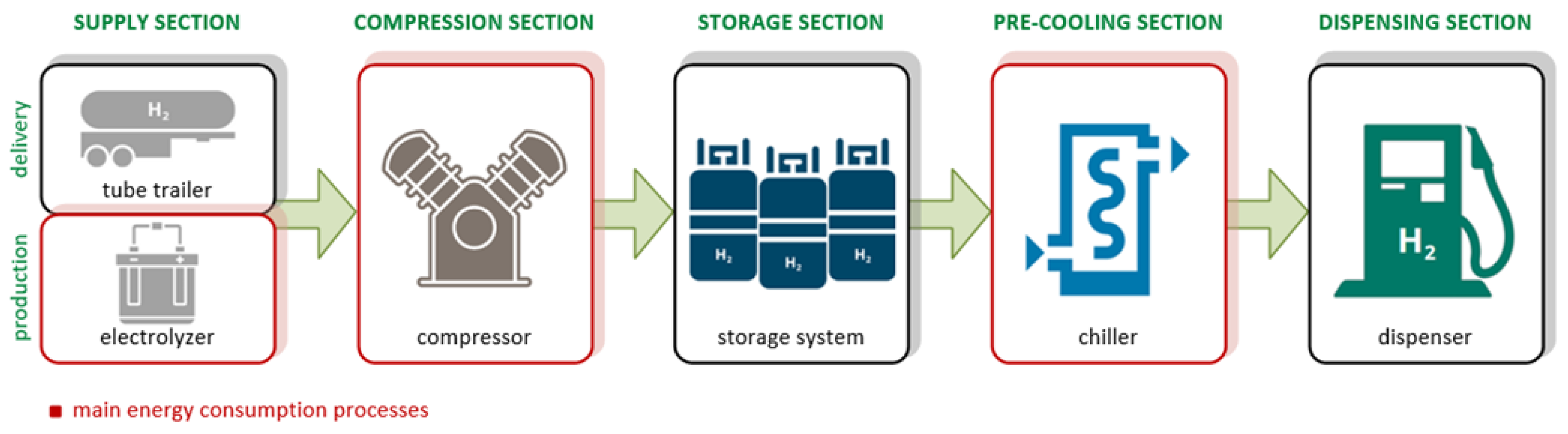
7. Energy Consumption in Hydrogen Refueling Stations

The costs of operating expenditure (OPEX) in HRSs represent a major impact on the costs of these infrastructures. The energy consumption required for an HRS to operate daily has a crucial influence on OPEX [73]. HRSs are mainly driven by OPEX, with transportation and electricity accounting for more than 80% of global costs [40]. The OPEX can also impact the levelized cost of hydrogen (LCOH), which is the price for a unit of hydrogen delivered [74]. In an off-site HRS with external hydrogen supply sources, the hydrogen supply cost represents more than 50% of the LCOH, although, in an on-site HRS, the power costs are the predominant element affecting the LCOH [75]. Energy consumption is, therefore, a major factor in the viability of on-site HRSs, and it is essentially present in three main processes, namely, the electrolysis process, the compression process and the pre-cooling process. According to these processes, the main elements that contribute to energy consumption can also be identified, which are the electrolyzer, the compressor and the chiller [76]. Figure 4 highlights these processes in the sections of HRSs.
The electrolysis process, performed by the electrolyzer, is related to the production process and is the process that requires the most energy compared to the other processes mentioned [76]. Considering the daily energy demand, the electrolyzer has the predominant rate, reaching around 88.5% of the daily energy demand over 24 h [77]. The electrolyzer has a highly specific electricity consumption of more than 50 kWh per kg of hydrogen produced and, therefore, electricity prices lead OPEX to dominate the LCOH [78]. The efficiency of each type of electrolyzer is also a factor that influences electricity costs, so the higher the efficiency of the electrolyzer, the lower the energy consumption per kg of hydrogen produced [79]. Of the four types of electrolyzer present, SOE is the one with the highest efficiency and, consequently, the lowest energy consumption, while PEM usually has a higher energy consumption, which is generally explained by the fact that they also operate at a higher pressure during the electrolysis process [80].
To raise the hydrogen pressure, the compressor also needs to consume energy, which is dependent on the power of the compressor and the time it is in operation. The compressor operating time is dependent on the quantity of mass that the tank requires to be fully filled, and the compressor power becomes higher as the pressure ratio between the pressure inlet and pressure outlet increases, so the power required is greater when refilling a high-pressure tank [81]. The energy required is also influenced by the compression and storage system utilized in the HRS, with the cascade refueling system presenting lower energy consumption, achieving overall savings of around 34% in energy consumption [82]. Depending on the type of compressor installed in the HRS, the specific energy consumption could differ. Electrochemical compressors, on average, have an energy consumption value bellow 4 kWh per kg of hydrogen produced, and metal hydride compressors have the highest energy consumption, because of the low thermal conductivity of the absorbent materials and the high heat of absorption, with a relatively high value of 10 kWh per kg of hydrogen produced [56]. In relation to the types of mechanical compressors, piston compressors and diaphragm compressors have an energy consumption value of less than 5 kWh per kg of hydrogen produced, while ionic liquid compressors account for an energy consumption of approximately 2.7 kWh per kg of hydrogen produced [56].
As the chiller pre-cools the hydrogen to a negative temperature, it also involves energy consumption and, therefore, energy costs, as it needs an energy supply to carry out the operation. The energy intensity for pre-cooling the hydrogen depends heavily on the utilization rate of HRSs. Taking into account the impact of the level of utilization, there is a range of energy intensities between 0.5 kWh per kg of hydrogen produced and 50 kWh per kg of hydrogen produced, with the result that for a utilization of more than 60%, there is an electricity consumption of less than 1 kWh per kg of hydrogen produced, approaching a value of 0.3 kWh per kg of hydrogen produced when the capacity of the HRS is fully utilized [83]. Upon full operation, the electrical energy needed to pre-cool hydrogen is expected to be approximately 10% of the total energy consumption of an HRS [84]. As the amount of hydrogen dispensed daily increases, the energy savings become also more efficient. For an HRS with a capacity of 180 kg per day, it is possible to obtain an improvement in energy efficiency of about 1.2% to 5.5%, while for a capacity of 360 kg per day, the improvements can be greater, with savings of between 2.9% and 8% [85]. The energy demand of the pre-cooling system is reduced when using more storage tanks [86], and, for a refueling process up to 350 bar, the cascade system requires less than 12% to 20% of energy to pre-cool the hydrogen [87]. However, reducing pre-cooling energy barely impacts the global energy savings, since pre-cooling only accounts for 4% of the energy demand for compression [86].

Energy Management Strategies

Within the scope of the strategic approaches found in the literature to reduce energy costs in HRSs, some common solutions stand out. Particularly, the use of renewable energy sources is a factor that forms part of most of the operating methodologies in the studies carried out. That methodology can be justified by the fact that renewable energy sources enable on-site HRSs to move away from a dependance on electricity prices and their use and, consequently, the production of green hydrogen has the potential to become an attractive option, especially when combined with low electricity prices [40].
Although some of these strategies include the use and sharing of the power grid, different approaches are considered, which differ according to some of the articles in the literature. Therefore, the operating methodologies in the literature are defined according to the availability and production of the energy sources in HRSs [76,88,89,90,91,92,93,94] or according to the hourly management of the operating processes in HRSs [95,96]. For the last two articles, the method involved managing the scheduling of operational processes at an hourly level, which may be dependent on the hours of demand and electricity prices. On the other hand, in most articles, the method prioritizes the availability of energy produced by renewable sources, as well as the use of energy from the electrical power grid when there is no production from renewable sources. In the study presented in [88], the authors conclude that the proposed optimized system could produce 58,615 kg of hydrogen per year, reducing CO2 emissions by 8209 kg per year. Table 4 compares and summarizes the methodologies used.

8. Conclusions

The success of using hydrogen in the mobility sector requires a competitive and mature technology, which is highly dependent on the development of HRSs. This development needs to overcome some barriers, namely technological and economic challenges. The economic challenges are present not only from the initial investments but also during HRS operation. This review focused on HRS operation, considering the various processes during vehicle refueling, the key processes that contribute for the operating costs associated with energy consumption and the main operation methodologies related to energy management strategies found in the literature. Energy consumption is a relevant parameter to consider for the deployment of HRSs, essential in on-site HRSs. The production of hydrogen in an HRS, carried out by the electrolyzer, is the process that requires the most energy consumption of all possible processes during HRS operation, and, so, if it is decided to be a necessary process for HRSs, it is important to develop methodologies for optimizing costs. The operation methodologies found in the literature aim to reduce the energy costs by using and sharing the power grid, and, in most articles, the operation management is based on the use of renewable energy sources. The inclusion of renewable sources is seen as an advantage for operational management, and it can be concluded from the related studies that it is a viable solution with economic benefits for the operation of HRSs. The use of renewable energy sources is also particularly important for the purpose of the decarbonization target, although it also involves investments costs, and, primarily, it may be necessary to combine the use of the electrical power grid with renewable energy sources to optimize profits. In future research, an economic analysis alongside a life cycle assessment of HRSs could be important for a better comprehension of and enhancement in the benefits of implementing this type of infrastructure. As the years go by, it is expected that the costs of HRSs and renewable energy source technologies will be reduced and, as a result, there will be significant economic benefits to the successful transition to hydrogen.

Author Contributions

Conceptualization, R.P. and J.T.; methodology, R.P.; validation, R.P.; investigation, R.P., V.M. and J.L.A.; writing—original draft preparation, R.P.; writing—review and editing, R.P., V.M. and J.L.A.; supervision, V.M. All authors have read and agreed to the published version of the manuscript.

Funding

This research received no external funding.

Acknowledgments

This work was supported by FCT—Fundação para a Ciência e Tecnologia—within the R&D Units Project Scope: UIDB/00319/2020.

Conflicts of Interest

Authors Rafael Pereira and Joni Teixeira were employed by the Petrotec. The remaining authors declare that the research was conducted in the absence of any commercial or financial relationships that could be construed as a potential conflict of interest.

References

  1. Williams, I.D.; Blyth, M. Autogeddon or Autoheaven: Environmental and Social Effects of the Automotive Industry from Launch to Present. Sci. Total Environ. 2023, 858, 159987. [Google Scholar] [CrossRef] [PubMed]
  2. Pramuanjaroenkij, A.; Kakaç, S. The Fuel Cell Electric Vehicles: The Highlight Review. Int. J. Hydrogen Energy 2023, 48, 9401–9425. [Google Scholar] [CrossRef]
  3. Transportation Emissions Worldwide—Statistics & Facts. Available online: https://www.statista.com/topics/7476/transportation-emissions-worldwide/#topicOverview (accessed on 24 November 2023).
  4. Tiseo, I. Annual Global Emissions of Carbon Dioxide 1940–2023. Available online: https://www.statista.com/statistics/276629/global-co2-emissions/ (accessed on 8 December 2023).
  5. Kinsella, L.; Stefaniec, A.; Foley, A.; Caulfield, B. Pathways to Decarbonising the Transport Sector: The Impacts of Electrifying Taxi Fleets. Renew. Sustain. Energy Rev. 2023, 174, 113160. [Google Scholar] [CrossRef]
  6. Albatayneh, A.; Juaidi, A.; Jaradat, M.; Manzano-Agugliaro, F. Future of Electric and Hydrogen Cars and Trucks: An Overview. Energy 2023, 16, 3230. [Google Scholar] [CrossRef]
  7. Gao, F. Hydrogen Fuel Cell Electric Vehicles: State of Art and Outlooks. In Proceedings of the 2022 IEEE 9th International Conference on Power Electronics Systems and Applications (PESA), Hong Kong, 20–22 September 2022. [Google Scholar]
  8. Silvestri, L.; Di Micco, S.; Forcina, A.; Minutillo, M.; Perna, A. Power-to-Hydrogen Pathway in the Transport Sector: How to Assure the Economic Sustainability of Solar Powered Refueling Stations. Energy Convers. Manag. 2022, 252, 115067. [Google Scholar] [CrossRef]
  9. Hydrogen Insights 2023 December Update. Available online: https://hydrogencouncil.com/en/hydrogen-insights-2023-december-update/ (accessed on 13 December 2023).
  10. Aravindan, M.; Hariharan, V.S.; Narahari, T.; Kumar, A.; Madhesh, K.; Kumar, P.; Prabakaran, R. Fuelling the Future: A Review of Non-Renewable Hydrogen Production and Storage Techniques. Renew. Sustain. Energy Rev. 2023, 188, 113791. [Google Scholar] [CrossRef]
  11. Ishaq, H.; Dincer, I.; Crawford, C. A Review on Hydrogen Production and Utilization: Challenges and Opportunities. Int. J. Hydrogen Energy 2022, 47, 26238–26264. [Google Scholar] [CrossRef]
  12. Smitkova, M.F.; Janicek, F.; Martins, F. Hydrogen Economy: Brief Sumarization of Hydrogen Economy. In Proceedings of the 2022 International Conference on Electrical, Computer and Energy Technologies (ICECET), Prague, Czech Republic, 20–22 July 2022. [Google Scholar]
  13. Camões, M.F.; Anes, B. Hydrated Protons. In Reference Module in Chemistry, Molecular Sciences and Chemical Engineering; Elsevier: Amsterdam, The Netherlands, 2019. [Google Scholar]
  14. Momirlan, M.; Veziroglu, T. The Properties of Hydrogen as Fuel Tomorrow in Sustainable Energy System for a Cleaner Planet. Int. J. Hydrogen Energy 2005, 30, 795–802. [Google Scholar] [CrossRef]
  15. Abe, I. Physical and Chemical Properties of Hydrogen. In Energy Carriers and Conversion Systems with Emphasis on Hydrogen; EOLSS Publications: Chiba, Japan, 2009; pp. 50–55. [Google Scholar]
  16. Sobre o Hidrogénio. Available online: https://www.ap2h2.pt/sobre-h2.php (accessed on 11 December 2023).
  17. Makridis, S.S. Hydrogen Storage and Compression. Methane Hydrog. Energy Storage 2016, 1, 1–28. [Google Scholar] [CrossRef]
  18. Souto, H.; Nogueira, T. O Hidrogénio Como Vetor Energético Do Futuro. Neutro À Terra 2024, 32, 49–55. [Google Scholar] [CrossRef]
  19. Hassan, Q.; Sameen, A.Z.; Salman, H.M.; Jaszczur, M.; Al-Jiboory, A.K. Hydrogen Energy Future: Advancements in Storage Technologies and Implications for Sustainability. J. Energy Storage 2023, 72, 108404. [Google Scholar] [CrossRef]
  20. Farias, C.B.B.; Barreiros, R.C.S.; da Silva, M.F.; Casazza, A.A.; Converti, A.; Sarubbo, L.A. Use of Hydrogen as Fuel: A Trend of the 21st Century. Energies 2022, 15, 311. [Google Scholar] [CrossRef]
  21. Al-Ahmed, A.; Hossain, S.; Mukhtar, B.; Rahman, S.U.; Abualhamayel, H.; Zaidi, J. Hydrogen Highway: An Overview. In Proceedings of the 2010 IEEE International Energy Conference, Manama, Bahrain, 18–22 December 2010. [Google Scholar]
  22. Alazemi, J.; Andrews, J. Automotive Hydrogen Fuelling Stations: An International Review. Renew. Sustain. Energy Rev. 2015, 48, 483–499. [Google Scholar] [CrossRef]
  23. Zhao, T.; Liu, Z. Investment of Hydrogen Refueling Station Based on Compound Real Options. Int. J. Hydrogen Energy 2024, 57, 198–209. [Google Scholar] [CrossRef]
  24. Escamilla, A.; Sánchez, D.; García-Rodríguez, L. Assessment of Power-to-Power Renewable Energy Storage Based on the Smart Integration of Hydrogen and Micro Gas Turbine Technologies. Int. J. Hydrogen Energy 2022, 47, 17505–17525. [Google Scholar] [CrossRef]
  25. Mio, A.; Barbera, E.; Massi Pavan, A.; Bertucco, A.; Fermeglia, M. Sustainability Analysis of Hydrogen Production Processes. Int. J. Hydrogen Energy 2024, 54, 540–553. [Google Scholar] [CrossRef]
  26. Hren, R.; Vujanović, A.; Van Fan, Y.; Klemeš, J.J.; Krajnc, D.; Čuček, L. Hydrogen Production, Storage and Transport for Renewable Energy and Chemicals: An Environmental Footprint Assessment. Renew. Sustain. Energy Rev. 2023, 173, 113113. [Google Scholar] [CrossRef]
  27. Hassan, Q.; Algburi, S.; Sameen, A.Z.; Salman, H.M.; Jaszczur, M. Green Hydrogen: A Pathway to a Sustainable Energy Future. Int. J. Hydrogen Energy 2024, 50, 310–333. [Google Scholar] [CrossRef]
  28. Junior, O.; Laurindo, D. O HIDROGÊNIO COMO VETOR ENERGÉTICO. In Estudos Interdisciplinares: Ciências Exatas e da Terra e Engenharias; Atena Editora: Ponta Grossa, Brasil, 2018; pp. 150–166. [Google Scholar]
  29. Arsad, A.Z.; Hannan, M.A.; Al-Shetwi, A.Q.; Begum, R.A.; Hossain, M.J.; Ker, P.J.; Mahlia, T.I. Hydrogen Electrolyser Technologies and Their Modelling for Sustainable Energy Production: A Comprehensive Review and Suggestions. Int. J. Hydrogen Energy 2023, 48, 27841–27871. [Google Scholar] [CrossRef]
  30. Zainal, B.S.; Ker, P.J.; Mohamed, H.; Ong, H.C.; Fattah, I.M.R.; Rahman, S.M.A.; Nghiem, L.D.; Mahlia, T.M.I. Recent Advancement and Assessment of Green Hydrogen Production Technologies. Renew. Sustain. Energy Rev. 2024, 189, 113941. [Google Scholar] [CrossRef]
  31. El-Shafie, M. Hydrogen Production by Water Electrolysis Technologies: A Review. Results Eng. 2023, 20, 101426. [Google Scholar] [CrossRef]
  32. Tang, D.; Tan, G.-L.; Li, G.-W.; Liang, J.-G.; Ahmad, S.M.; Bahadur, A.; Humayun, M.; Ullah, H.; Khan, A.; Bououdina, M. State-of-the-Art Hydrogen Generation Techniques and Storage Methods: A Critical Review. J. Energy Storage 2023, 64, 107196. [Google Scholar] [CrossRef]
  33. Shiva Kumar, S.; Lim, H. An Overview of Water Electrolysis Technologies for Green Hydrogen Production. Energy Rep. 2022, 8, 13793–13813. [Google Scholar] [CrossRef]
  34. Benghanem, M.; Mellit, A.; Almohamadi, H.; Haddad, S.; Chettibi, N.; Alanazi, A.M.; Dasalla, D.; Alzahrani, A. Hydrogen Production Methods Based on Solar and Wind Energy: A Review. Energy 2023, 16, 757. [Google Scholar] [CrossRef]
  35. Sebbahi, S.; Nabil, N.; Alaoui-Belghiti, A.; Laasri, S.; Rachidi, S.; Hajjaji, A. Assessment of the Three Most Developed Water Electrolysis Technologies: Alkaline Water Electrolysis, Proton Exchange Membrane and Solid-Oxide Electrolysis. Mater. Today Proc. 2022, 66, 140–145. [Google Scholar] [CrossRef]
  36. Chang, S.H.; Rajuli, M.F. An Overview of Pure Hydrogen Production via Electrolysis and Hydrolysis. Int. J. Hydrogen Energy 2024, 84, 521–538. [Google Scholar] [CrossRef]
  37. Becker, H.; Murawski, J.; Shinde, D.V.; Stephens, I.E.L.; Hinds, G.; Smith, G. Impact of Impurities on Water Electrolysis: A Review. Sustain. Energy Fuels 2023, 7, 1565–1603. [Google Scholar] [CrossRef]
  38. Lindquist, G.A.; Xu, Q.; Oener, S.Z.; Boettcher, S.W. Membrane Electrolyzers for Impure-Water Splitting. Joule 2020, 4, 2549–2561. [Google Scholar] [CrossRef]
  39. Tarhan, C.; Çil, M.A. A Study on Hydrogen, the Clean Energy of the Future: Hydrogen Storage Methods. J. Energy Storage 2021, 40, 102676. [Google Scholar] [CrossRef]
  40. Caponi, R.; Bocci, E.; Del Zotto, L. Techno-Economic Model for Scaling Up of Hydrogen Refueling Stations. Energy 2022, 15, 7518. [Google Scholar] [CrossRef]
  41. Genovese, M.; Fragiacomo, P. Hydrogen Refueling Station: Overview of the Technological Status and Research Enhancement. J. Energy Storage 2023, 61, 106758. [Google Scholar] [CrossRef]
  42. Tian, Z.; Lv, H.; Zhou, W.; Zhang, C.; He, P. Review on Equipment Configuration and Operation Process Optimization of Hydrogen Refueling Station. Int. J. Hydrogen Energy 2022, 47, 3033–3053. [Google Scholar] [CrossRef]
  43. Choi, D.; Lee, S.; Kim, S. A Thermodynamic Model for Cryogenic Liquid Hydrogen Fuel Tanks. Appl. Sci. 2024, 14, 3786. [Google Scholar] [CrossRef]
  44. Zhang, T.; Uratani, J.; Huang, Y.; Xu, L.; Griffiths, S.; Ding, Y. Hydrogen Liquefaction and Storage: Recent Progress and Perspectives. Renew. Sustain. Energy Rev. 2023, 176, 113204. [Google Scholar] [CrossRef]
  45. Rong, Y.; Chen, S.; Li, C.; Chen, X.; Xie, L.; Chen, J.; Long, R. Techno-Economic Analysis of Hydrogen Storage and Transportation from Hydrogen Plant to Terminal Refueling Station. Int. J. Hydrogen Energy 2024, 52, 547–558. [Google Scholar] [CrossRef]
  46. Zhang, G.; Jiang, Z. Overview of Hydrogen Storage and Transportation Technology in China. Unconv. Resour. 2023, 3, 291–296. [Google Scholar] [CrossRef]
  47. Bosu, S.; Rajamohan, N. Recent Advancements in Hydrogen Storage—Comparative Review on Methods, Operating Conditions and Challenges. Int. J. Hydrogen Energy 2024, 52, 352–370. [Google Scholar] [CrossRef]
  48. Chalkiadakis, N.; Stubos, A.; Stamatakis, E.; Zoulias, E.; Tsoutsos, T. A Review on Hydrogen Compression Methods for Hydrogen Refuelling Stations. In Hydrogen Electrical Vehicles; Scrivener Publishing: Beverly, MA, USA, 2023; pp. 47–73. [Google Scholar]
  49. Okonkwo, P.C.; Barhoumi, E.M.; Ben Belgacem, I.; Mansir, I.B.; Aliyu, M.; Emori, W.; Uzoma, P.C.; Beitelmal, W.H.; Akyüz, E.; Radwan, A.B.; et al. A Focused Review of the Hydrogen Storage Tank Embrittlement Mechanism Process. Int. J. Hydrogen Energy 2023, 48, 12935–12948. [Google Scholar] [CrossRef]
  50. Shin, H.K.; Ha, S.K. A Review on the Cost Analysis of Hydrogen Gas Storage Tanks for Fuel Cell Vehicles. Energies 2023, 16, 5233. [Google Scholar] [CrossRef]
  51. Cheng, Q.; Zhang, R.; Shi, Z.; Lin, J. Review of Common Hydrogen Storage Tanks and Current Manufacturing Methods for Aluminium Alloy Tank Liners. Int. J. Lightweight Mater. Manuf. 2023, 7, 269–284. [Google Scholar] [CrossRef]
  52. Jin, Z.; Su, Y.; Lv, H.; Liu, M.; Li, W.; Zhang, C. Review of Decompression Damage of the Polymer Liner of the Type IV Hydrogen Storage Tank. Polymers 2023, 15, 2258. [Google Scholar] [CrossRef] [PubMed]
  53. Air, A.; Shamsuddoha, M.; Gangadhara Prusty, B. A Review of Type V Composite Pressure Vessels and Automated Fibre Placement Based Manufacturing. Compos. B Eng. 2023, 253, 110573. [Google Scholar] [CrossRef]
  54. Zou, J.; Han, N.; Yan, J.; Feng, Q.; Wang, Y.; Zhao, Z.; Fan, J.; Zeng, L.; Li, H.; Wang, H. Electrochemical Compression Technologies for High-Pressure Hydrogen: Current Status, Challenges and Perspective. Electrochem. Energy Rev. 2020, 3, 690–729. [Google Scholar] [CrossRef]
  55. Orlova, S.; Mezeckis, N.; Vasudev, V.P.K. Compression of Hydrogen Gas for Energy Storage: A Review. Latv. J. Phys. Tech. Sci. 2023, 60, 4–16. [Google Scholar] [CrossRef]
  56. Sdanghi, G.; Maranzana, G.; Celzard, A.; Fierro, V. Towards Non-Mechanical Hybrid Hydrogen Compression for Decentralized Hydrogen Facilities. Energy 2020, 13, 3145. [Google Scholar] [CrossRef]
  57. Sdanghi, G.; Maranzana, G.; Celzard, A.; Fierro, V. Review of the Current Technologies and Performances of Hydrogen Compression for Stationary and Automotive Applications. Renew. Sustain. Energy Rev. 2019, 102, 150–170. [Google Scholar] [CrossRef]
  58. Zhou, H.; Ooi, K.T.; Dong, P.; Yang, Z.; Zhou, S.; Zhao, S. Dynamic and Energy Analysis of a Liquid Piston Hydrogen Compressor. Int. J. Hydrogen Energy 2023, 48, 20694–20704. [Google Scholar] [CrossRef]
  59. Caponi, R.; Ferrario, A.M.; Bocci, E.; Bødker, S.; del Zotto, L. Single-Tank Storage versus Multi-Tank Cascade System in Hydrogen Refueling Stations for Fuel Cell Buses. Int. J. Hydrogen Energy 2022, 47, 27633–27645. [Google Scholar] [CrossRef]
  60. Bartolucci, L.; Cordiner, S.; Mulone, V.; Tatangelo, C.; Antonelli, M.; Romagnuolo, S. Multi-Hub Hydrogen Refueling Station with on-Site and Centralized Production. Int. J. Hydrogen Energy 2023, 48, 20861–20874. [Google Scholar] [CrossRef]
  61. Park, B.H.; Joe, C.H. Investigation of Configuration on Multi-Tank Cascade System at Hydrogen Refueling Stations with Mass Flow Rate. Int. J. Hydrogen Energy 2024, 49, 1140–1153. [Google Scholar] [CrossRef]
  62. Chen, G.; Su, S.; Xu, Q.; Lv, H.; Zhao, Y.; Xia, L.; Zhang, G.; Hu, K. Optimization of Hydrogen Refueling Strategy: Based on Energy Consumption and Refueling Demand. Int. J. Hydrogen Energy 2024, 71, 625–636. [Google Scholar] [CrossRef]
  63. Sadi, M.; Deymi-Dashtebayaz, M. Hydrogen Refueling Process from the Buffer and the Cascade Storage Banks to HV Cylinder. Int. J. Hydrogen Energy 2019, 44, 18496–18504. [Google Scholar] [CrossRef]
  64. Rothuizen, E.; Rokni, M. Optimization of the Overall Energy Consumption in Cascade Fueling Stations for Hydrogen Vehicles. Int. J. Hydrogen Energy 2014, 39, 582–592. [Google Scholar] [CrossRef]
  65. Genovese, M.; Cigolotti, V.; Jannelli, E.; Fragiacomo, P. Current Standards and Configurations for the Permitting and Operation of Hydrogen Refueling Stations. Int. J. Hydrogen Energy 2023, 48, 19357–19371. [Google Scholar] [CrossRef]
  66. Wang, X.; Fu, J.; Liu, Z.; Liu, J. Review of Researches on Important Components of Hydrogen Supply Systems and Rapid Hydrogen Refueling Processes. Int. J. Hydrogen Energy 2023, 48, 1904–1929. [Google Scholar] [CrossRef]
  67. Chochlidakis, C.-G.; Rothuizen, E.D. Overall Efficiency Comparison between the Fueling Methods of SAEJ2601 Using Dynamic Simulations. Int. J. Hydrogen Energy 2020, 45, 11842–11854. [Google Scholar] [CrossRef]
  68. Fueling Protocols for Light Duty Gaseous Hydrogen Surface Vehicles. Available online: https://www.sae.org/standards/content/j2601_202005/ (accessed on 4 January 2024).
  69. Luo, H.; Xiao, J.; Bénard, P.; Yang, T.; Tong, L.; Chahine, R.; Yuan, Y.; Yuan, C.; Yao, C. Improvement of MC Method in SAE J2601 Hydrogen Refuelling Protocol Using Dual-Zone Dual-Temperature Model. J. Energy Storage 2024, 81, 110416. [Google Scholar] [CrossRef]
  70. Reddi, K.; Elgowainy, A.; Rustagi, N.; Gupta, E. Impact of Hydrogen SAE J2601 Fueling Methods on Fueling Time of Light-Duty Fuel Cell Electric Vehicles. Int. J. Hydrogen Energy 2017, 42, 16675–16685. [Google Scholar] [CrossRef]
  71. Bauer, A.; Mayer, T.; Semmel, M.; Guerrero Morales, M.A.; Wind, J. Energetic Evaluation of Hydrogen Refueling Stations with Liquid or Gaseous Stored Hydrogen. Int. J. Hydrogen Energy 2019, 44, 6795–6812. [Google Scholar] [CrossRef]
  72. Li, J.-Q.; Chen, Y.; Ma, Y.B.; Kwon, J.-T.; Xu, H.; Li, J.-C. A Study on the Joule-Thomson Effect of during Filling Hydrogen in High Pressure Tank. Case Stud. Therm. Eng. 2023, 41, 102678. [Google Scholar] [CrossRef]
  73. Yu, Y.; Lu, C.; Ye, S.; Hua, Z.; Gu, C. Optimization on Volume Ratio of Three-Stage Cascade Storage System in Hydrogen Refueling Stations. Int. J. Hydrogen Energy 2022, 47, 13430–13441. [Google Scholar] [CrossRef]
  74. Greene, D.L.; Ogden, J.M.; Lin, Z. Challenges in the Designing, Planning and Deployment of Hydrogen Refueling Infrastructure for Fuel Cell Electric Vehicles. eTransportation 2020, 6, 100086. [Google Scholar] [CrossRef]
  75. Wu, L.; Zhu, Z.; Feng, Y.; Tan, W. Economic Analysis of Hydrogen Refueling Station Considering Different Operation Modes. Int. J. Hydrogen Energy 2023, 52, 1577–1591. [Google Scholar] [CrossRef]
  76. Pagano, A.; Gabbar, H. Techno-Economic Analysis of a Hydrogen Refueling Station Located in Turin. In Proceedings of the IEEE 11th International Conference on Smart Energy Grid Engineering (SEGE), Oshawa, ON, Canada, 13–15 August 2023. [Google Scholar]
  77. Fragiacomo, P.; Genovese, M. Numerical Simulations of the Energy Performance of a PEM Water Electrolysis Based High-Pressure Hydrogen Refueling Station. Int. J. Hydrogen Energy 2020, 45, 27457–27470. [Google Scholar] [CrossRef]
  78. Caponi, R.; Monforti Ferrario, A.; Del Zotto, L.; Bocci, E. Hydrogen Refueling Station Cost Model Applied to Five Real Case Studies for Fuel Cell Buses. E3S Web Conf. 2021, 312, 07010. [Google Scholar] [CrossRef]
  79. Zun, M.T.; McLellan, B.C. Cost Projection of Global Green Hydrogen Production Scenarios. Hydrogen 2023, 4, 932–960. [Google Scholar] [CrossRef]
  80. Poudineh, R.; Patonia, A. Cost-Competitive Green Hydrogen: How to Lower the Cost of Electrolysers? Available online: https://www.oxfordenergy.org/publications/cost-competitive-green-hydrogen-how-to-lower-the-cost-of-electrolysers/ (accessed on 6 December 2023).
  81. Blazquez-Diaz, C. Techno-Economic Modelling and Analysis of Hydrogen Fuelling Stations. Int. J. Hydrogen Energy 2019, 44, 495–510. [Google Scholar] [CrossRef]
  82. Xiao, L.; Chen, J.; Wu, Y.; Zhang, W.; Ye, J.; Shao, S.; Xie, J. Effects of Pressure Levels in Three-Cascade Storage System on the Overall Energy Consumption in the Hydrogen Refueling Station. Int. J. Hydrogen Energy 2021, 46, 31334–31345. [Google Scholar] [CrossRef]
  83. Elgowainy, A.; Reddi, K.; Lee, D.-Y.; Rustagi, N.; Gupta, E. Techno-Economic and Thermodynamic Analysis of Pre-Cooling Systems at Gaseous Hydrogen Refueling Stations. Int. J. Hydrogen Energy 2017, 42, 29067–29079. [Google Scholar] [CrossRef]
  84. Talpacci, E.; Reuβ, M.; Grube, T.; Cilibrizzi, P.; Gunnella, R.; Robinius, M.; Stolten, D. Effect of Cascade Storage System Topology on the Cooling Energy Consumption in Fueling Stations for Hydrogen Vehicles. Int. J. Hydrogen Energy 2018, 43, 6256–6265. [Google Scholar] [CrossRef]
  85. Genovese, M.; Blekhman, D.; Dray, M.; Fragiacomo, P. Improving Chiller Performance and Energy Efficiency in Hydrogen Station Operation by Tuning the Auxiliary Cooling. Int. J. Hydrogen Energy 2022, 47, 2532–2546. [Google Scholar] [CrossRef]
  86. Maurer, W.; Justl, M.; Keuschnigg, R. Improving Hydrogen Refueling Stations to Achieve Minimum Refueling Costs for Small Bus Fleets. Int. J. Hydrogen Energy 2023, 48, 29821–29834. [Google Scholar] [CrossRef]
  87. Genovese, M.; Blekhman, D.; Dray, M.; Piraino, F.; Fragiacomo, P. Experimental Comparison of Hydrogen Refueling with Directly Pressurized vs. Cascade Method. Energy 2023, 16, 5749. [Google Scholar] [CrossRef]
  88. Barhoumi, E.M.; Okonkwo, P.C.; Ben Belgacem, I.; Zghaibeh, M.; Tlili, I. Optimal Sizing of Photovoltaic Systems Based Green Hydrogen Refueling Stations Case Study Oman. Int. J. Hydrogen Energy 2022, 47, 31964–31973. [Google Scholar] [CrossRef]
  89. Song, L.; Gao, W.; Zhang, L.; Li, Q.; Ren, H. Economic Analysis of a Photovoltaic Hydrogen Refueling Station Based on Hydrogen Load. Energy 2023, 16, 6406. [Google Scholar] [CrossRef]
  90. Minutillo, M.; Perna, A.; Forcina, A.; Di Micco, S.; Jannelli, E. Analyzing the Levelized Cost of Hydrogen in Refueling Stations with On-Site Hydrogen Production via Water Electrolysis in the Italian Scenario. Int. J. Hydrogen Energy 2021, 46, 13667–13677. [Google Scholar] [CrossRef]
  91. Tang, O.; Rehme, J.; Cerin, P. Levelized Cost of Hydrogen for Refueling Stations with Solar PV and Wind in Sweden: On-Grid or off-Grid? Energy 2022, 241, 122906. [Google Scholar] [CrossRef]
  92. Di Micco, S.; Minutillo, M.; Perna, A.; Jannelli, E. On-Site Solar Powered Refueling Stations for Green Hydrogen Production and Distribution: Performances and Costs. E3S Web Conf. 2022, 334, 01005. [Google Scholar] [CrossRef]
  93. Jing, S.; Yonggang, P.; Jia, X. A Photovoltaic-Assisted in-Situ Hydrogen Refueling Station System and Its Capacity Optimization Method. In Proceedings of the 2023 5th Asia Energy and Electrical Engineering Symposium (AEEES), Chengdu, China, 23–26 March 2023. [Google Scholar]
  94. Maurer, W.; Rechberger, P.; Justl, M.; Keuschnigg, R. Parameter Study for Dimensioning of a PV Optimized Hydrogen Supply Plant. Int. J. Hydrogen Energy 2022, 47, 40815–40825. [Google Scholar] [CrossRef]
  95. Shams, M.H.; Niaz, H.; Liu, J.J. Energy Management of Hydrogen Refueling Stations in a Distribution System: A Bilevel Chance-Constrained Approach. J. Power Sources 2022, 533, 231400. [Google Scholar] [CrossRef]
  96. Lu, D.; Sun, J.; Peng, Y.; Chen, X. Optimized Operation Plan for Hydrogen Refueling Station with On-Site Electrolytic Production. Sustainability 2022, 15, 347. [Google Scholar] [CrossRef]
Figure 1. Hydrogen production methods [24].
Energies 17 04906 g001
Figure 2. Electrolyzer system for hydrogen production with power electronics representation.
Energies 17 04906 g002
Figure 3. Five types of gaseous hydrogen storage tanks.
Energies 17 04906 g003
Figure 4. HRS sections and the key energy consumption processes.
Energies 17 04906 g004
Table 1. Main advantages and disadvantages of each type of electrolyzer [29,33,34,35].
TechnologyAdvantagesDisadvantages
AWEMature technology
Low capital cost
High stability
Longer lifetime
Low hydrogen purity
Low operational pressure
Lower current density
Corrosivity of electrolyte
Slow startup
Gas permeation
PEMHigh hydrogen purity
High current density
Compact and simple design
Quick response time
High dynamic operation
High membrane cost
Acidic environment
Lower durability
AAEMHigh hydrogen purity
Simple design
Low cost
Low concentrated liquid electrolyte
Low lifetime
Low ionic conductivity
Low membrane stability
SOEHigh efficiency
Low capital cost
Requires low energy
Safety and sealing problems
Uses brittle material
Unstable electrodes
Table 2. Description of the types of gaseous hydrogen storage tanks.
TypeMaterial Characteristic
IAll-metal gas tank
IIMetal-lined gas tank hoop-wound with fiber
IIIMetal-lined gas tank fully wound with fiber
IVPolymer-lined gas tank fully wound with fiber
VAll-composite liner-less gas tank
Table 3. Advantages and disadvantages of compressor types [56,57].
Types of CompressorsAdvantagesDisadvantages
Piston compressorMature technology
Adaptability to a large range of flow rates
High discharge pressures
Embrittlement phenomena
Several moving parts
Manufacturing and maintenance complexity
Difficulty in managing heat transfer
Presence of vibrations and noise
Not suitable for high compression ratios
Diaphragm compressorMature technology
Low cooling requirement
Ideal for handling pure gases and explosives
Diaphragm failure
Complex design
Limited throughput
Ionic liquid compressorHigh efficiency
High compression ratio
Low energy consumption
Low noise emissions
No gas contamination
Reduced wear and long service
Quite isothermal compression
Small number of moving parts
Liquid leaks
Cavitation phenomena
Corrosion
Metal hydride compressorThermally driven compressor
Absence of moving parts
Compact design
Safety
Absence of noise
High-purity hydrogen production
High desorption temperature
High heat of absorption
Limited heat transfer
Necessity of using appropriate alloys
Low efficiency
High weight
Low compression rates
Electrochemical compressorLow cost of operation
Absence of moving parts
High-purity hydrogen production
Very high compression efficiency
Use as a purifier
Difficulty in manufacturing the cell assembly
Difficulty in realizing a perfect sealing
High cell resistance
Not suitable for very high discharge pressures
Low compression rates
Table 4. Summary of the strategies used in the literature for energy management in HRSs.
ArticleElectricity Prices AnalysisUse of Renewable Sources AnalysisStrategy Based on Electricity PricesStrategy Based on Renewable Production
[76]NoYesNoYes
[88]NoYesNoYes
[89]YesYesYesYes
[90]YesYesYesYes
[91]YesYesYesYes
[92]NoYesNoYes
[93]YesYesYesYes
[94]YesYesYesYes
[95]YesYesYesYes
[96]YesNoYesNo
Disclaimer/Publisher’s Note: The statements, opinions and data contained in all publications are solely those of the individual author(s) and contributor(s) and not of MDPI and/or the editor(s). MDPI and/or the editor(s) disclaim responsibility for any injury to people or property resulting from any ideas, methods, instructions or products referred to in the content.

