Article

Advanced Fuel Based on Semi-Coke and Cedarwood: Kinetic Characteristics and Synergetic Effects

1
Polytechnic School, Siberian Federal University, 79, Svobodny Avenue, Krasnoyarsk 660041, Russia
2
Research School of High-Energy Physics, National Research Tomsk Polytechnic University, 30, Lenin Avenue, Tomsk 634050, Russia
3
Thermo and Fluid Dynamics (FLOW), Faculty of Engineering, Vrije Universiteit Brussel (VUB), Pleinlaan 2, 1050 Brussels, Belgium
4
Brussels Institute for Thermal-Fluid Systems and Clean Energy (BRITE), Vrije Universiteit Brussel (VUB) and Université Libre de Bruxelles (ULB), 1050 Brussels, Belgium
*
Author to whom correspondence should be addressed.
Energies 2024, 17(19), 4963; https://doi.org/10.3390/en17194963
Submission received: 25 August 2024 / Revised: 1 October 2024 / Accepted: 1 October 2024 / Published: 4 October 2024

Abstract

:
This paper presents the results of analytical studies of the combustion process of semi-coke, cedar sawdust, and their mixtures using the TGA method at three different heating rates with the determination of the main characteristics of heating: the presence of synergetic interaction between the components of the mixture affecting the maximum rate of combustion and kinetic parameters. Calculations of activation energy and pre-exponential multiplier of the Arrhenius equation by the Friedman and Ozawa–Flynn–Wall priori methods for initial combustibles and their mixtures have been carried out. Semi-coke was obtained by thermal treatment of brown coal at 700–900 °C to remove volatile substances, which makes it more environmentally friendly than the original coal. Semi-coke has a higher heat of combustion than biomass, and biomass has a higher reactivity than semi-coke. The combustion process of biomass occurs in a lower temperature range, and adding biomass to semi-coke shifts the combustion process to a lower temperature range than such for biomass. Adding at least 50% of biomass to semi-coke increases the combustion index by at least 1.1 times. Regardless of the heating rate of mixtures, synergetic interaction between the mixture’s components increases the maximum combustion rate of coke residue by 20%.

1. Introduction

The consumption of solid fossil fuels for heat and electricity generation in the world reaches 40% compared to other energy fuels [1,2]. Reducing coal consumption and improving environmental performance is currently an urgent scientific and practical task. One of the available ways to realize this task is the addition of biomass to coal, which allows for the reduction of coal consumption, reduced harmful emissions (sulfur oxides and nitrogen oxides), reduced CO2 emissions, reduced emissions of fine ash particles, and does not require large-scale reconstruction of equipment [3,4,5].
Considering the issue of a feasibility study of the transition to coal co-combustion (semi-coke produced from coal), it can be noted that biomass is considered waste from any production, for example, in the wood processing industry, and is conditionally free fuel due to the fact that the enterprise needs to utilize its waste at its own expense. In this case, the cost of biomass will depend only on the distance of its delivery to the heat power facilities, so biomass will be cheaper than coal, which will improve the technical and economic performance of the boiler house. In addition, it is proved that the cost of reconstruction of a coal-fired boiler house will be lower than the cost required for the construction of a new biomass-fired boiler house [6]. If payments for harmful emissions and CO2 emissions are taken into account for the technical and economic indicators of the boiler house, these payments will be reduced when switching to the combustion of biomass-based mixtures due to the fact that biomass is a carbon-neutral fuel and less harmful emissions, such as sulphur oxides and nitrogen oxides, are emitted during combustion [7].
Semi-coke produced in the process of the thermal treatment of coal by gasification or pyrolysis is obtained as waste or as a product. In the case of synthesis gas production for the chemical industry, semi-coke is waste with low calorific value [8] and is stored in special landfills. Such waste is sometimes used to produce thermal energy, but there are a number of problems associated with its combustion in power plants. Most of the problems with the combustion of semi-coke are related to the low content of volatile substances, which reduces the maneuverability of power plants due to the high ignition and burnout temperature of semi-coke. Semi-coke, produced as high-calorie furnace fuel for the metallurgical industry, is not used as energy fuel for boilers. The reason for this is that the process of heat energy production becomes more expensive as the cost of energy fuel increases due to the process of thermal treatment before its combustion in boilers. Therefore, semi-coke obtained as waste is expediently burned in a mixture with highly reactive coals or biomass [9], and semi-coke obtained for the metallurgical industry [10] and having a high calorific value is expediently partially burned together with free biomass waste.
In the process of investigating the co-combustion of semi-coke and different types of biomass (corn stalk, rice stalk, and pine wood), it was found that the addition of biomass has an effect on reducing the ignition and burnout temperature of the mixture [11]. Liu H.-P. et al. [12] investigated the co-combustion of waste from the thermal treatment of oil shale and torrefied corn stalks and found that the change in activation energy was affected by increasing the proportion of biomass in the mixture. During the combustion of a mixture based on coal and char, the presence of synergetic effects affecting the ignition temperature due to an increase in volatile substances in the mixture was found, as well as an increase in the average combustion temperature of fuel particles, which affects the improvement in combustion efficiency of the mixture [13]. Qin H. et al. [14], in the study of co-combustion of semi-coke and biomass using thermo-gravimetric analysis, found that biomass burns more efficiently than semi-coke and that the heating rate (too low or too high) affects the reaction time, which adversely affects combustion, and they also noted the presence of synergistic effects. When combusting semi-coke and hard coal together, the proportion of semi-coke in the mixture should not exceed 45%. The addition of semi-coke to coal leads to a decrease in the combustion index of the mixture and an increase in the activation energy [15]. The NO content of co-combustion of semi-coke and hard coal decreases as the proportion of coal in the mixture increases [16,17]. Zhao R. et al. [18] investigated the co-combustion of lignite and semi-coke and found that increasing the proportion of lignite in the mixture affects the reduction in CO and CO2, while NO emissions increase and semi-coke has a suppressive effect on nitrogen and sulfur oxide emissions.
The purpose of this study is to comprehensively investigate the combustion of industrial semi-coke produced for the metallurgical industry and forest biomass, taking into account flue gas analysis and synergistic effects. For the first time, the influence of heating rate on the interaction of mixture components with each other was analyzed, taking into account the main combustion characteristics. The results of the study can be applied in the design of power plants and in CFD modeling of furnace devices and processes.

2. Materials and Methods

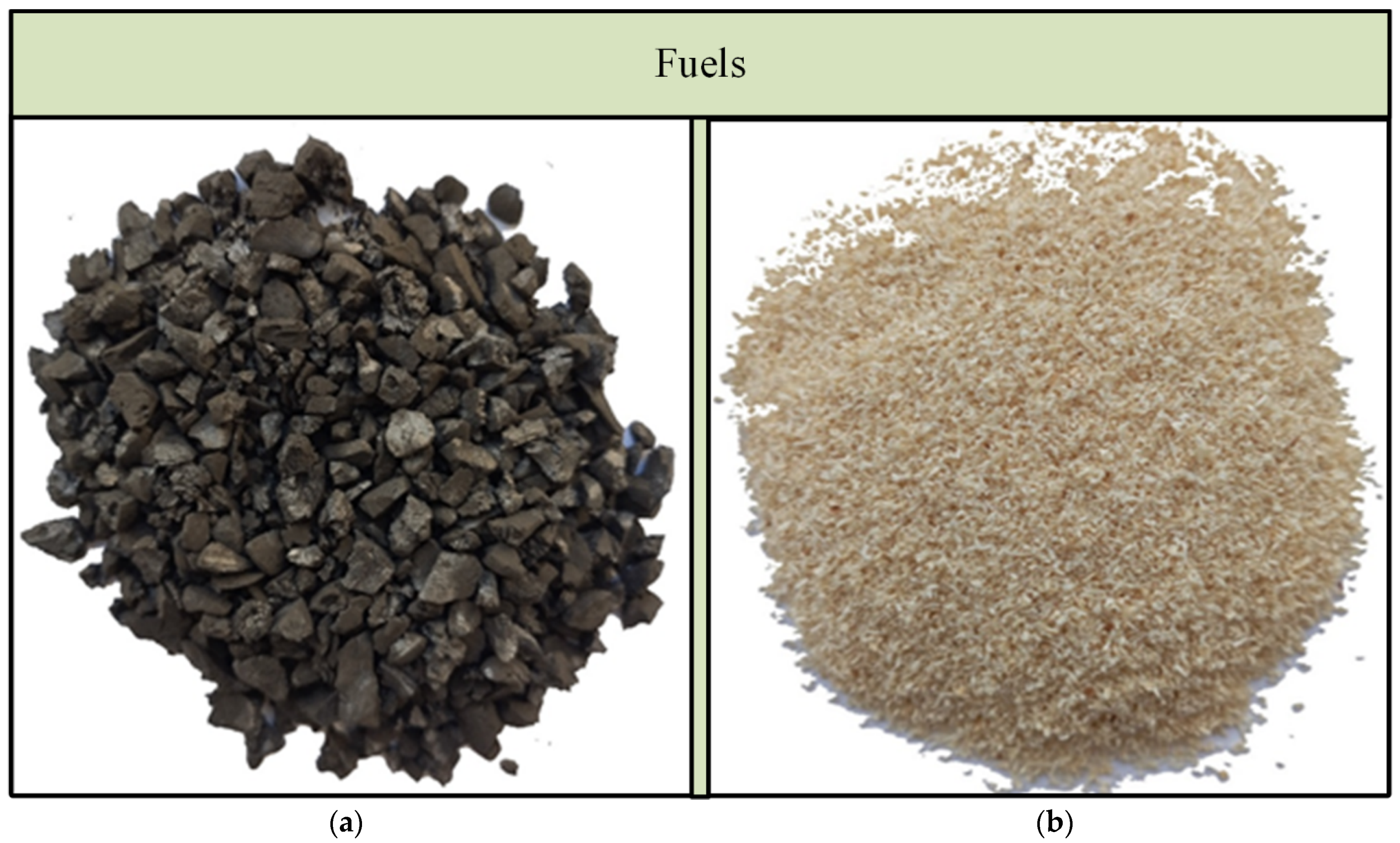
2.1. Materials and Sample Preparation

The following fuels and their mixtures (by mass) were selected as objects of research:
No. 1—semi-coke obtained from brown coal by gasification under conditions of oxidizer deficiency at a temperature of 700–900 °C, Russia.
No. 2—cedar sawdust, biomass waste obtained at a woodworking enterprise, Russia;
No. 3—a mixture based on semi-coke 75% + cedar sawdust 25%;
No. 4—a mixture based on semi-coke 50% + cedar sawdust 50%;
No. 5—a mixture based on semi-coke 25% + cedar sawdust 75%.
Visualization of the fuels is presented in Figure 1. Semi-coke is produced for use as an energy fuel in aluminum production or as sorbents in other industries. Semi-coke is not used as an energy fuel for heat generation due to its minimal content of volatile substances, which makes it less reactive, so it is advisable to burn it with highly reactive fuel, for example, biomass.
Cedar is used to produce furniture, sports equipment, and construction material; after its processing, it leaves a large amount of wood waste (sawdust), which must be disposed of in special landfills, as storage in the open air can lead to fire and, in the process of long storage, decomposing sawdust can harm the environment.
The fuels were studied after they reached the air-dry state. Coal and sawdust were separately ground in a Retsch DM200 (Haan, Germany), and then the dispersion of fuel particles 53–200 μm was obtained using a Retsch AS200 (Haan, Germany).
The calorimeter C6000 (IKA, Staufen, Germany) was used to determine the combustion heat; a Vario MACRO cube device (Elementar Analysensysteme GmbH, Langenselbold, Germany) was used to determine the content of carbon, hydrogen, and nitrogen; a humidity analyzer MA–150 (Sartorius, Göttingen, Germany) was used to determine the humidity; a muffle furnace Snol was used to determine the yield of volatile substances and ash content 7.2/1300 (AB “Umega”, Utena, Lithuania). Technical and elemental analyses were carried out according to the following standards: ISO 11722:1999, Solid mineral fuels—Bituminous coal—Determination of moisture in a sample for general analysis by drying in nitrogen; ISO 1171:2010, Solid mineral fuels—Determination of ash; ISO 562: 2010, Bituminous coal and coke—Determination of volatile matter; ISO 1928: 2009, Solid mineral fuels—Determination of gross calorific value by the bomb calorimetric method and calculation of net calorific value; ASTM D5373-14e1, Standard Test Methods for Determination of Carbon, Hydrogen and Nitrogen in Analysis Samples of Coal and Carbon in Analysis Samples of Coal and Coke, ASTM International, West Conshohocken, PA, 2014 [19,20,21,22,23]. The results of technical and elemental analyses of semi-coke (No. 1) and cedar sawdust (No. 2) are summarized in Table 1.
The combustion of fuels was investigated using a synchronous thermal analyzer SDT Q600 (TA Instruments Inc., New Castle, DE, USA). The experiments were carried out in airflow with a flow rate of 50 mL/min at heating rates of 10, 20, and 30 °C min−1; the weight of the sample was 5–6 mg. Universal Analysis 2000 software (Software v5.5.24, TA Instruments Inc., New Castle, DE, USA) was used to process the results of thermo-gravimetry (TG) and differential thermo-gravimetry (DTG). The experiments were repeated at least 2 times to achieve repeatability.

2.2. Combustion Characteristics

The TG results were used to determine the main combustion characteristics, including the fuel combustion index (S) [24,25,26], which was determined according to Formula (1). This quantitative characteristic is used in analyzing the combustibility of different fuels and takes into account the temperature at which ignition occurs, mass loss rates, and burnout temperature. A high value of the combustion index indicates that the fuel ignites at lower temperatures and has a higher combustion rate, which in turn affects the conditions for completing the combustion process at lower temperatures. When calculating the combustion index, the temperature at which carbon ignites (Ti) and the temperature at which the combustion process is completed (Tb) were used [27,28,29,30]. The temperatures at which the fuel ignition occurs and the combustion process is completed were determined using the curve crossing method.
The combustion index is calculated using the following formula:
S = R D T G · R m e a n T i 2 · T b ,
where RDTGmaximum rate of fuel mass loss, % min−1; Rmean—average rate of fuel mass loss from ignition to complete burnout of its carbon residue, % min−1; Ti and Tb—temperatures corresponding to ignition and carbon burnout, °C; S—combustion index, min−2 °C−3.

2.3. Estimation Methods of Synergy

To analyze the influence of components in the combustion of a mixture, experimental (exp) and calculated (est) data were compared. The calculated data were obtained using Formula (2) [18,31,32]:
DTGest = x1DTG1 + x2DTG2,
where DTG1 and DTG2—values of maximum rate of mass loss for each fuel (DTG1—semi-coke; DTG2—sawdust), % min−1; x1 and x2—values of fuel content in the mixture, their sum should be equal to one.

2.4. Kinetic Analysis
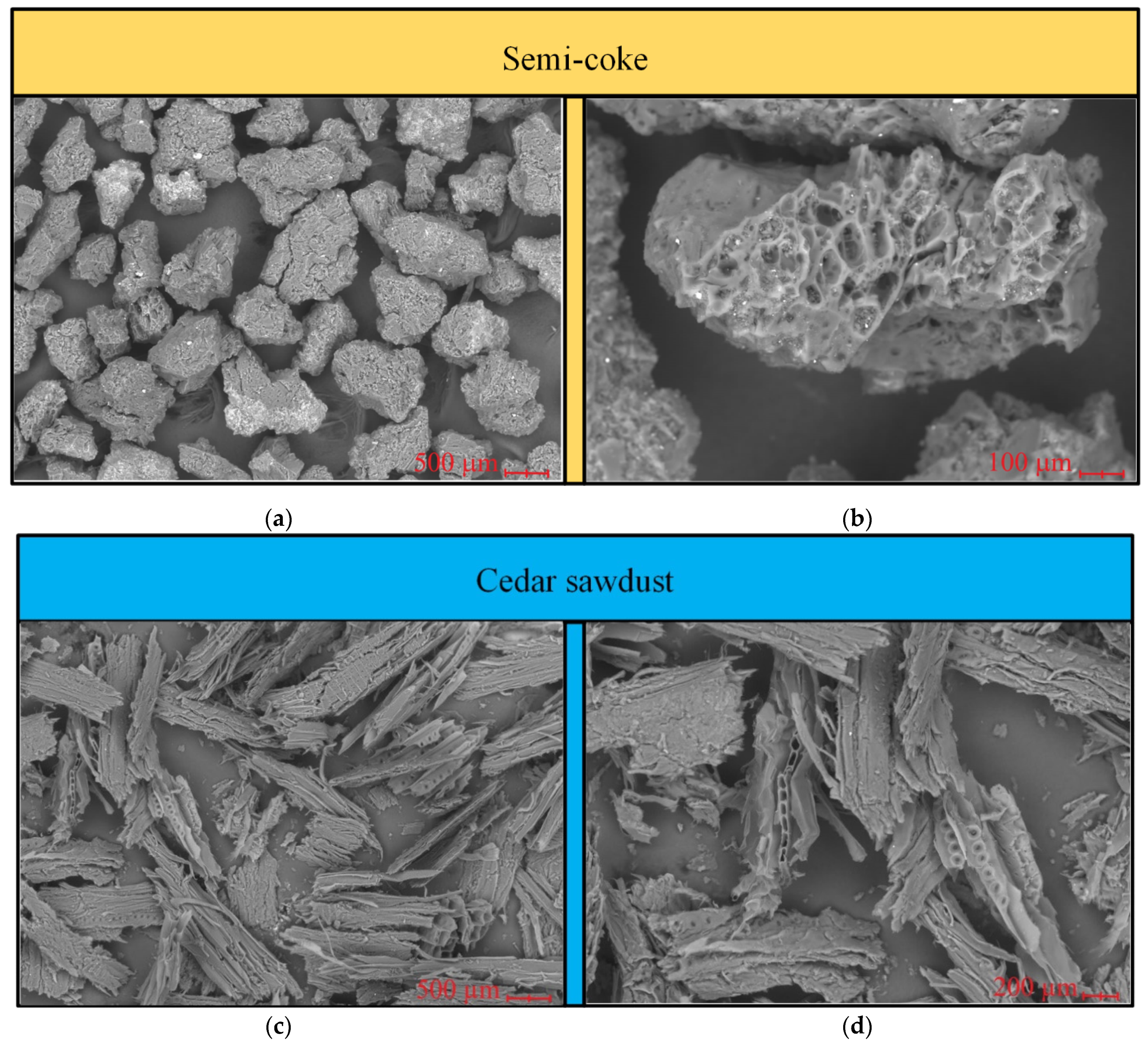
Kinetic analysis was performed on TGA data using NETZSCH Thermokinetics software (NETZSCH-Geraetebau GmbH, Selb, Germany). The values of such kinetic parameters as activation energy (Ea) and pre-exponential multiplier (A) were determined using Friedman and Ozawa–Flynn–Wall (OFW) models.
These models are based on the kinetic equation derived from the law of acting masses, which defines the reaction rate dα/dt as the product of the rate constant (k) and the concentration of the starting substance to a degree equal to the reaction order (f (α)). In turn, the rate constant is a function of temperature, described by the Arrhenius Equation (3):
k = A∙exp (−Ea/RT),
where R is the gas constant, and T is the temperature. Thus, the basic kinetic equation of the heterogeneous process is described in expression 4 as follows:
d α d t = k ( T ) · f ( α ) ,
where α is the degree of transformation of the substance.
The Friedman and Ozawa–Flynn–Wall models refer to isoconversion methods of kinetic analysis, which assumes that each point of the experimental TGA curve corresponds to a certain value of the degree of conversion (x), proportional to the degree of transformation of the substance during the chemical reaction. The calculation of x is carried out according to Expression (5):
x i = m t s m ( t i ) m t s m ( t f ) ,
where xi is the degree of conversion at time ti, m(ts) is the signal at the initial time ts, m(ti) is the signal at time ti, and m(ft) is the signal at the final time tf.
Friedman [33] proposed to use the logarithm of the rate of change of conversion dx/dt as a function of the corresponding temperature, represented in Expression (6):
ln d x d t x = x i = ln A E a R T + ln f ( x i ) ,
Considering that f (x) is constant for a given xi, the dependence in coordinates ln dx/dt = f (1/T) is described by a straight line with slope m = −Ea/R.
The pre-exponential multiplier is evaluated assuming that f (x) = (1 – xi), which is true for the first-order reaction, in which case A is calculated from Expression (7):
l n A = l n d x d t x = x i + E a R T + l n ( 1 x i ) ,
Independently of each other, Ozawa [34] and Flynn and Wall [35] developed a method for determining the activation energy from data from a series of dynamic measurements with different heating rates (β). If the heating rate is constant in time β = dT/dt, expression (4) is transformed into Expression (8):
d α d T = 1 β k ( T ) · f ( α ) ,
Taking into account (3), this expression, when integrating, takes the form of Expression (9):
0 α d α f ( α ) = A β · T 0 T e x p E a R T d T = G α ,
where Ga is the integral conversion function, which is constant at a constant value of xi.
After logarithmizing (9), the equation is represented by Expression (10):
ln G α = ln A · E a R ln β + ln p z ,
where p z = e x p ( z ) z z e x p ( z ) z d z , z = Ea/RT. Using Doyle’s approximation [36], it is obtained that ln pz = −5.3305 – 1.052∙z and substituting this value into (10) gives Expression (11):
0 α d α f ( α ) = A β · T 0 T e x p E a R T d T = G α ,
Considering that Ga is constant for a given xi, the dependence in coordinates ln β = f (1/T) is described by a straight line with slope m = −1.052∙Ea/R.
When averaged over all heating rates, equation (10) leads to the determination of the values of the pre-exponential multiplier assuming a first-order reaction when Gα in Expression (12):
ln A = ln ( ln ( 1 x i ) ) ln E a R + ln β ln p z

2.5. SEM

Scanning electron microscopy (SEM) was performed on a TM-4000 microscope (HITACHI High-Technologies Corporation, Chiba, Japan) to analyze the surface texture of particles of solid fuels (semicoke and sawdust). The main characteristics of the microscope: magnification from ×10 to ×100,000 times; depth of field 0.5 mm; accelerating voltage from 5 kV to 15 kV; maximum sample size up to 80 mm in diameter and up to 50 mm in height; minimum displacement step is 65 nm. The TM-4000 microscope is equipped with a microanalysis system for Hitachi TM4000Plus benchtop microscope (HITACHI High-Technologies Corporation, Chiba, Japan): silicon-drift detector with a working area of 30 mm2; guaranteed energy resolution: 137 eV (Mn Ka); electron source is a pre-centered tungsten cathode. The main functionality of the TM-4000 microscope is to obtain and process magnified images of the sample surface in backscattered electrons (BSE) and secondary electrons (SE).
Figure 2 shows SEM images showing the surface area of semi-coke and biomass fuel particles. Generally, the specific surface area of the coal particle is small compared to biomass because the presence of pores, cracks, and channels in the fuel particles increases the specific surface area. In its structure, the biomass particle (Figure 2b,d) consists of a large number of different pores and crack channels through which, in the life process, fluid flows from the roots to the upper edge, nourishing the whole tree. High specific surface area primarily affects the ignition and combustion process of the fuel particle because, through the channels, pores, and cracks, the oxidizer (air) penetrates faster into the particle and reacts with carbon.
Unlike biomass, the surface of coal particles, especially bituminous coal and anthracite, may have no pores, cracks, or channels at all, while brown coal sometimes has small cracks. This, in turn, is one of the factors affecting the reactivity of the fuel, so the reactivity of coal is lower than that of biomass, but other factors must be taken into account.
Gasification of coal in the reactor at a temperature of 700–900 °C resulted in highly porous carbonizate differing from the original coal with a low content of volatile substances, high ash content, and high heat of combustion, which makes it particularly attractive for use as an energy fuel. When gaseous volatile substances escape from the depth of the particle during thermal treatment of coal, the surface of the semi-coke particle is ruptured, forming a large number of pores, cracks, and channels (Figure 2a,c).

2.6. Ash Analysis

The elemental composition of ash residue was analyzed as follows. The fuel with a mass of 2 g in a porcelain pot was placed in a muffle furnace, Heraeus K114 (Thermo Fisher Scientific Inc., Waltham, MA, USA), preheated to a temperature of 1000 °C. The holding time at this temperature was 1 h. The values of basic oxides included in the ashes of fuels No.1 and 2 are presented in Table 2.
Since semi-coke was obtained from brown coal, the chemical composition of the mineral part of ash is mainly represented by silicon oxide 46.1% and aluminum oxide 10% as well as iron oxide 13.7% and calcium oxide 23% (see Table 2). High content of these elements can intensify at high temperatures the process of slagging of heating surfaces on the basis of ferruginous deposits in the boiler furnace; therefore, this coal grade belongs to high slagging. In wood biomass, according to Table 2, high content of calcium oxide and potassium oxide in the ash is noted; these elements can also intensify the contamination of heating surfaces on the basis of active alkalis, which is characteristic of wood biomass. It is noted that the high SiO2 content of 10.5% is not characteristic of woody biomass and is most likely obtained in the form of fine sand during its storage or transportation. Detailed studies on the propensity of this type of coal and pine sawdust are presented in [37].
The heating process of individual fuels and fuel mixtures is shown below. Heating of fuels can be divided into three main stages: at the first stage of heating, there is evaporation of moisture; the second stage corresponds to the beginning of thermal decomposition, which develops into ignition and combustion of volatile substances contained in fuels; at the third stage, there is ignition and combustion of coke residue to the temperature corresponding to the completion of the combustion process of the carbon part of fuel particles, after which only unburnable ash residue remains. Only the second and third heating stages of fuels can be referred to as the combustion process in thermo-gravimetric analysis; the first heating stage usually takes place in the temperature range from the initial heating temperature to 110–130 °C, and the mass reduction in fuels is minimal due to the fact that the analytical moisture content is minimal (see Table 1). In real conditions, the working moisture content of semi-coke and biomass can be many times higher since the specific surface area formed by a large number of pores, cracks, and channels in both fuels is quite high, which will negatively affect the delivery and storage of these fuels in the open air, presenting an opportunity to increase the moisture content due to precipitation.

3. Results

This section presents the temperature ranges and time intervals of the second and third stages of combustion of fuels/fuel mixtures and the main combustion characteristics of individual fuels/fuel mixtures.

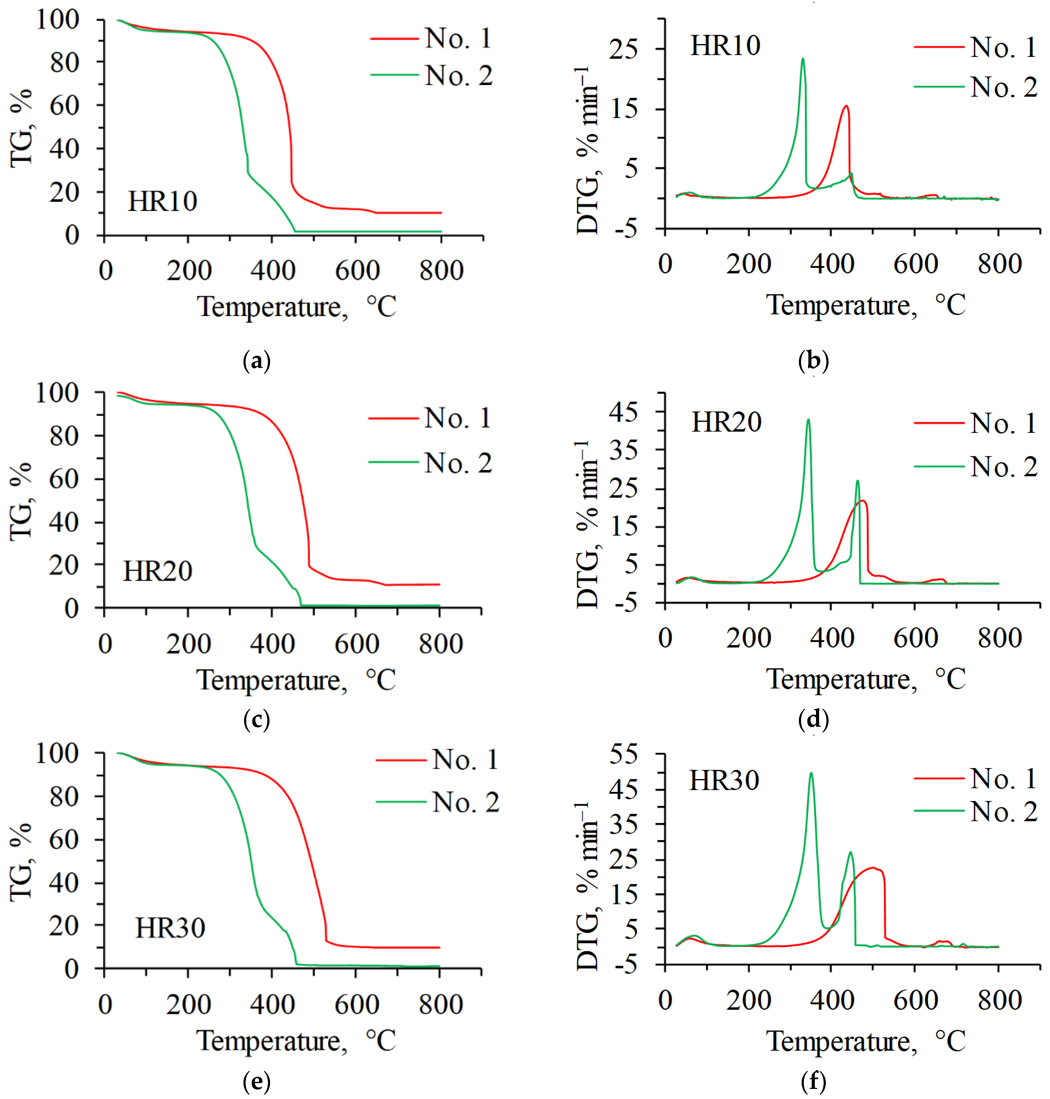
3.1. Individual Combustion

The onset of thermal decomposition of semi-coke at a heating rate of 10 °C min−1 occurs in the temperature range of 295–405 °C accompanied by the release of volatile substances (Figure 3a,b).
The ignition of coke residue occurs at 405 °C. The third stage of heating takes place in the temperature range of 406–653 °C and is characterized by the combustion of coke residue (Table 3), expressed by one large exothermic peak (see Figure 3b) with a maximum mass loss rate equal to 15.5% min−1 at a temperature of 436 °C. The combustion of semi-coke is completed at a temperature of 653. The combustion index of semi-coke was 6.5 min−2 °C−3.
When the heating rate is increased two and three times, the temperature range of the second heating stage shifts to higher temperatures up to 440 °C (see Figure 3c–f). In turn, this leads to an increase in the ignition temperature of coke residue up to 335–440 °C. Burning of coke residue, which occurs at the third stage of heating, shifts to the region of higher temperatures with increasing heating rate, and the process time decreases more than twice. The burnout temperature of semi-coke increases as the heating temperature increases. Increasing the ignition and burnout temperature did not affect the decrease in the combustion index; on the contrary, increasing the heating rate more than doubled the combustion index due to an increase in the maximum mass loss rate (Table 4).
Combustion of biomass volatiles at a heating rate of 10 °C/min occurs in the temperature range of 201–299 °C. Ignition of the coke residue takes place at a temperature of 299 °C. Burning of the coke residue takes place in the temperature range of 300–461 °C. The maximum mass loss rate was 23.5%/min. The burnout temperature was 461 °C. In general, it can be noted that the combustion of semi-coke and biomass takes place in different temperature ranges. The key factor here is the content of volatile substances, which is many times higher in biomass than in semi-coke (see Table 1). The combustion index of biomass is three times higher than that of semi-coke (Table 4).

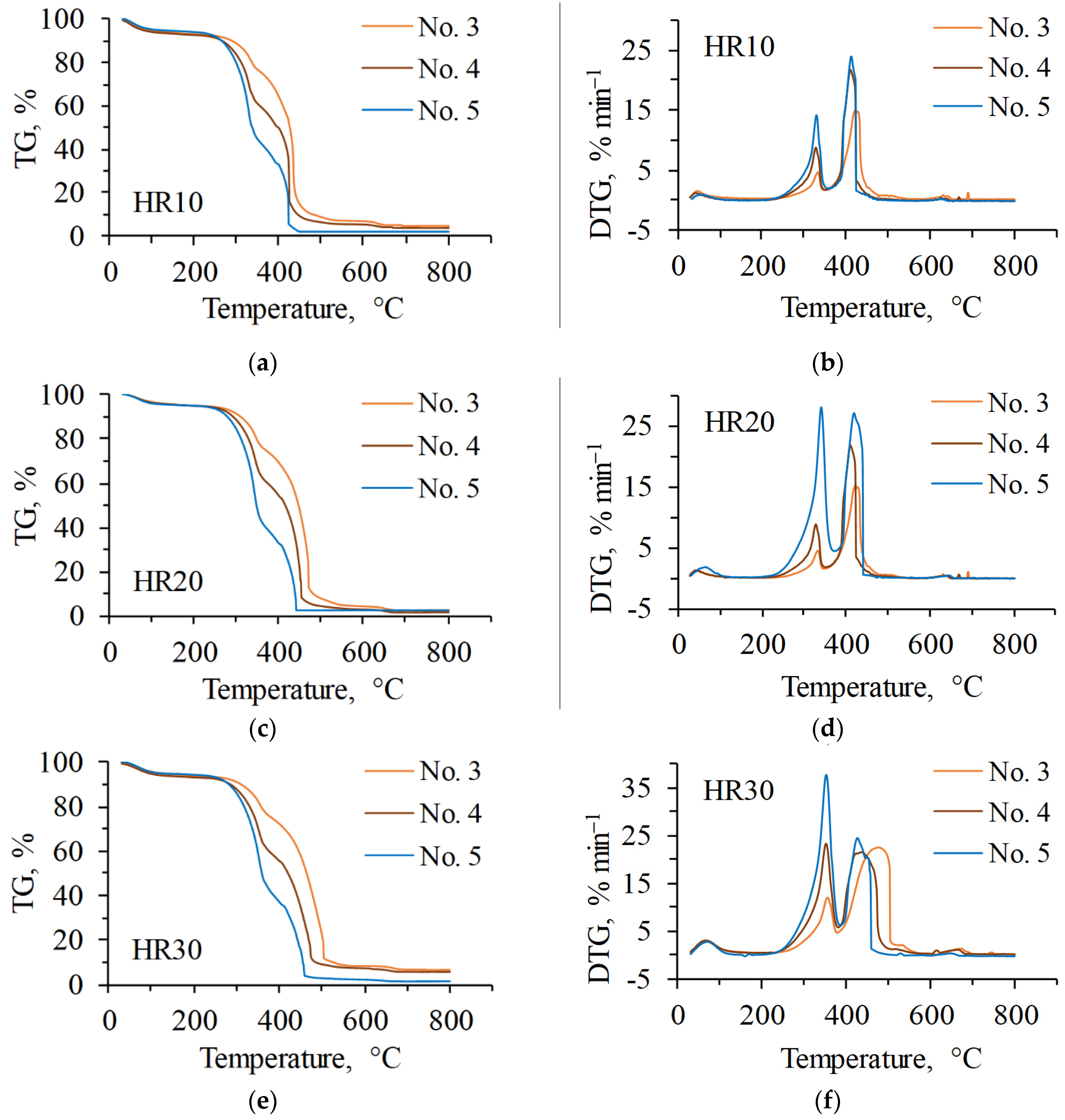
3.2. Co-Combustion Characteristics of Blends

The heating process of the mixtures at different heating rates is represented by the profiles of the TG and DTG curves in Figure 4.
The combustion process of mixtures No. 3–5 is expressed by two DTG maxima corresponding to the combustion of volatile substances of biomass and semi-coke residue. At the content of 25% of the biomass in the mixture (No. 3), the first maximum DTG is located in the temperature range of 240–349 °C and is characteristic of the combustion of volatile substances of biomass and part of the coke residue; the duration of the second stage was 21.2–5.1 min, depending on the heating rate (Table 3). The second maximum of DTG located in the temperature range of 350–644 °C is characteristic of the combustion of semi-coke residue and biomass; the duration of the third stage was 30.0–9.9 min. The total combustion time of mixture No. 3 was 51.2–15.0 min. The temperature at which the coke residue ignition occurred was 349–406 °C depending on the heating rate (Table 4), the burnout temperature was 644–689 °C, and the combustion index was 2.5–18.3 min−2 °C −3. The decrease in combustion index compared to semi-coke at heating rates of 10 and 20 °C min−1 is explained by the fact that the maximum rate of mass loss (RDTG) decreases, which is an indicator of fuel reactivity; the higher the RDTG value, the more reactive, and thus better burning, the fuel.
Increasing the share of biomass in the mixture up to 50% (No. 4) affects the decrease in the duration of the second stage of combustion by 6.6–2.9 min at different heating rates and shifts the temperature range of the second stage to lower temperatures of 233–301 °C. The duration of the third stage increased and amounted to 37.2–12.0 min. The total combustion time of the No. 4 mixture was 43.8–14.9 min (Table 3). The ignition temperature decreased and amounted to 301–318 °C due to an increase in the volatile content of the mixture. The burnout temperature was 669–675 °C. The combustion index at different rates was 7.2–16.6 min−2 °C−3 (Table 4).
In the mixture containing 75% of biomass (No. 5), the duration of the second stage (combustion of cellulose and hemicellulose contained in biomass) located in the temperature range of 216–301 °C was 8.0–3.5 min. The third stage took place in the temperature range of 302–625 °C with a duration of 33.1–5.9 min at different heating rates. The total combustion time of mixture No. 5 was 41.1–9.4 min, which was shorter than that of mixtures No. 3 and 4 (Table 3). The ignition temperature was 301–316 °C, and the burnout temperature was 625–489 °C. The combustion index of mixture No. 5 increased to 12.3–53.7 min−2 °C−3 due to an increase in the maximum rate of mass loss.
The addition of biomass to semi-coke had a positive effect on the reduction in ignition and burnout temperature. The addition of more than 25% biomass influences the increase in the combustion index of semi-coke due to the increase in volatile matter content in the mixture, in turn influencing its ignition at lower temperatures compared to semi-coke.

3.3. Interaction between Blend Components—Synergistic Effects

In this section, only the second and third stages of heating fuel mixtures at three heating rates will be considered. The analysis of the interaction of the mixture of component particles on each other is presented in Figure 5 in the form of DTG curve profiles. Comparisons of DTGexp (values obtained during the experiment) and DTGest (values obtained by calculation) curve profiles show the presence of additive combustion or the presence of synergetic effects expressed in the change of the maximum combustion rate at two combustion stages: Stage II corresponds to the temperature region of biomass volatile combustion; Stage III corresponds to the temperature region of coke residue combustion of mixture components. The results of DTGexp and DTGest at different heating rates and stages are presented in Table 5.
In mixture No. 3 (Figure 5a), the synergetic effect is manifested at Stage II and has a negative effect on the combustion process of volatile substances at a heating rate of 10 °C min−1, reducing the maximum combustion rate by 1.9% min−1; unburned volatile substances finish combustion at Stage III having a positive synergetic effect on the combustion of biomass coke residue and semi-coke. This is evidenced by an increase in the maximum combustion rate by 2.7% min−1 (Table 5). Increasing the heating rate of mixture No. 3 up to 20 °C min−1 (Figure 5d) leads to the strengthening of the negative synergistic effect expressed by the decrease in the maximum combustion rate in the experiment for combustion of volatile substances by 2.2% min−1 for combustion of biomass coke residue and semi-coke by 1% min−1. At a combustion rate of 30 °C min−1 (Figure 5g) at Stage II, the synergistic effect reduces the maximum combustion rate of volatile substances by 1.8% min−1 while enhancing the synergistic interaction of the mixture components between themselves expressed in the increase in the maximum combustion rate of Stage III by 2.1% min−1 (Table 5).
Analyzing the interaction of the components of mixture No. 4 between each other, it was found that, as well as in mixture No. 3, there is no additive combustion at both stages, and there is a synergetic interaction of mixture components between each other. At Stage II, there is a decrease in the maximum burning rate of volatiles by 3.3% min−1 (Figure 5b); at Stage III, the synergistic interaction increases the maximum burning rate of coke residue by 2.3 times (Table 5). By doubling the heating rate, the maximum volatile combustion rate decreases by 5.2% min−1 and runs in the same temperature range as the calculated values. At Stage III (Figure 5e), the experimental and calculated values do not differ significantly, only by 0.3% min−1 (Table 5), but the temperature interval in the experiment shifted to lower temperatures, thus affecting the reduction in the burn-up temperature. When the heating rate was increased to 30 °C min−1 (Figure 5h), there was a slight decrease in the maximum burning rate of volatiles by only 2.3% min−1, the profiles of DTGexp and DTGest curves coincide up to the peak, indicating the presence of additive combustion of volatiles. In coke residue combustion, the synergistic effects had a negative effect, reducing the maximum heating rate by 0.9% min−1 (Table 5).
In mixture No. 5 (Figure 5c), synergistic interactions between particle components were negatively affected during volatile combustion, reducing the maximum combustion rate by 3.4% min−1. In Stage III, the synergistic effects increased the maximum burning rate of the coke residue by 3.8 times, while the combustion region moved to lower temperatures compared to the calculated values, which also had a positive effect on the combustion process. Increasing the heating rate up to 20 °C min−1 (Figure 5f), in Stage II, there was a decrease in DTGexp by 4.4% min−1, and in Stage III, as a consequence of synergetic interactions of mixture components, the maximum heating rate increased by 1.8 and shifted to lower temperatures, which favorably affected the combustion of mixture No. 5. At a heating rate of 30 °C min−1 (Figure 5i), Stage II demonstrates additive combustion (i.e., the profiles of curves DTGexp and DTGest completely coincided). At Stage III, the maximum DTGexp and DTGest values differ by only 0.2% min−1, but the curve profiles did not coincide, indicating no additive combustion of biomass coke residue and semi-coke.
The analysis of the interaction between the particles of the mixture components has shown that the heating rate does not affect the synergetic effects. At increasing speed, synergetic effects in the combustion process of mixtures can be both positive and negative, affecting the change in the maximum combustion rate. It was found that in all the studied mixtures presented in Figure 4 on Stage II at combustion of volatile substances, the maximum burning speed is higher at calculated values; at experiment, it is lower.

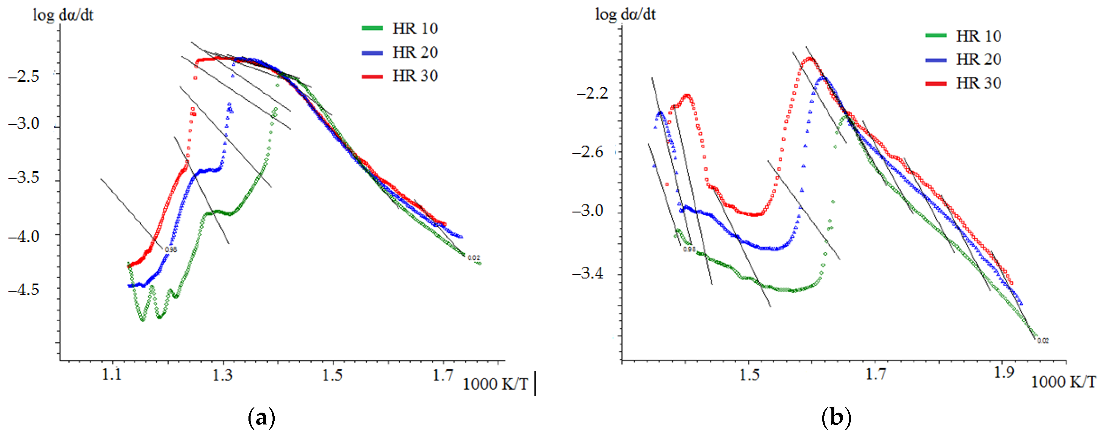
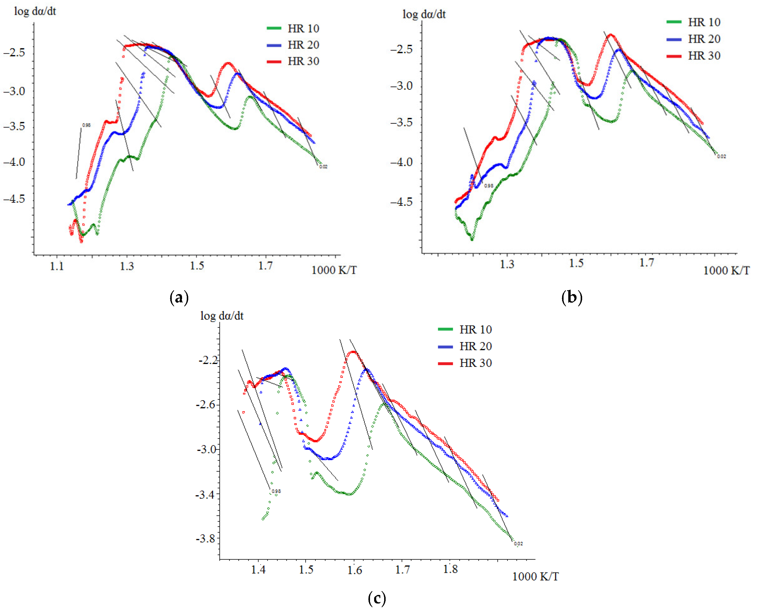
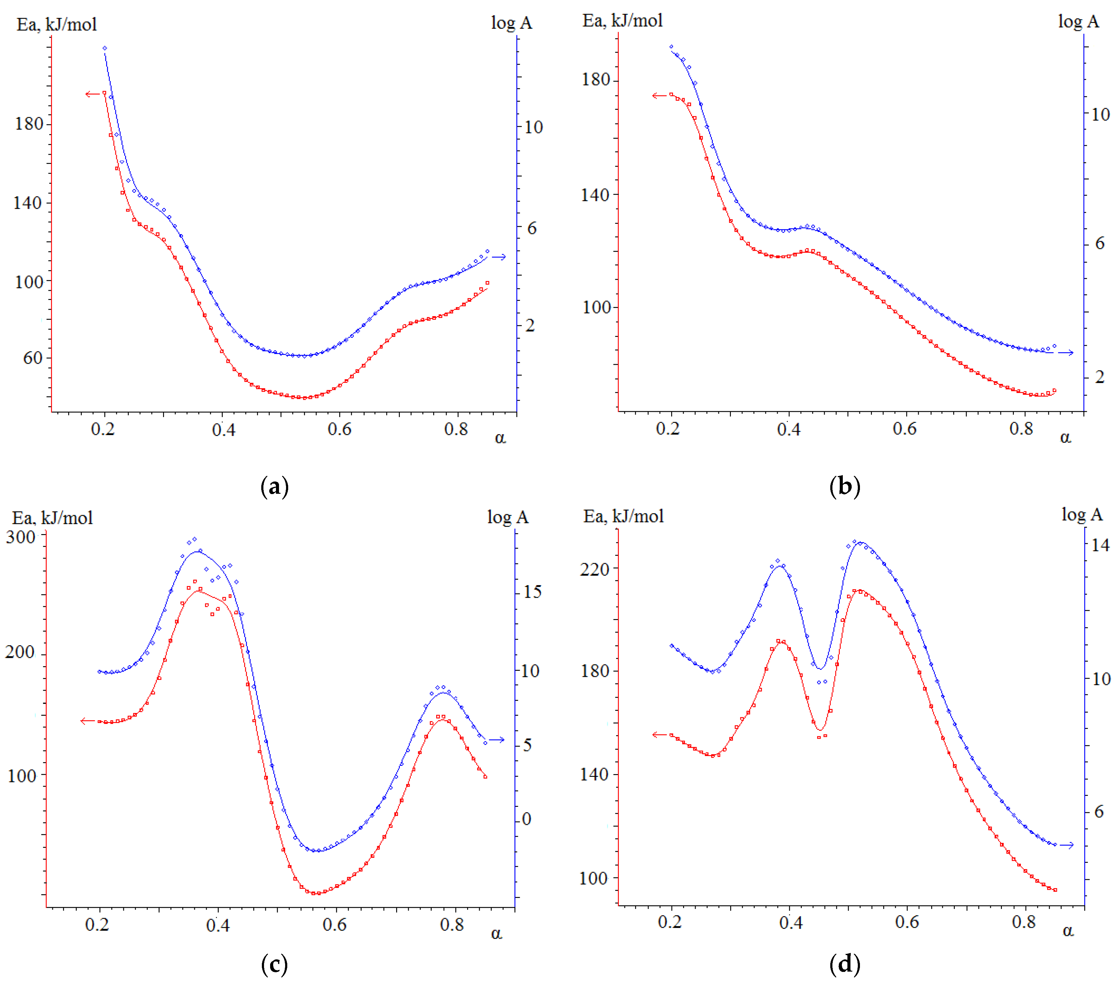
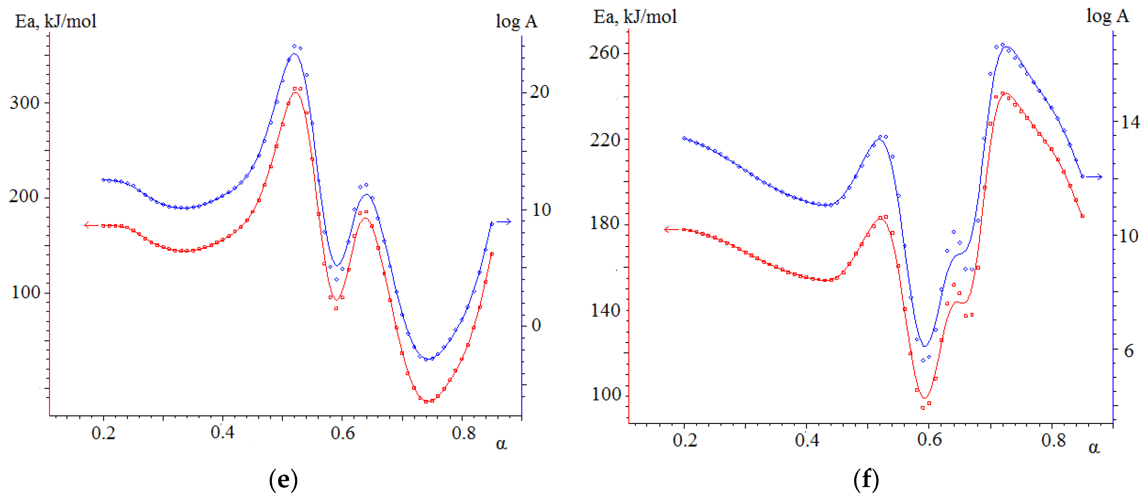
3.4. Kinetic Analysis

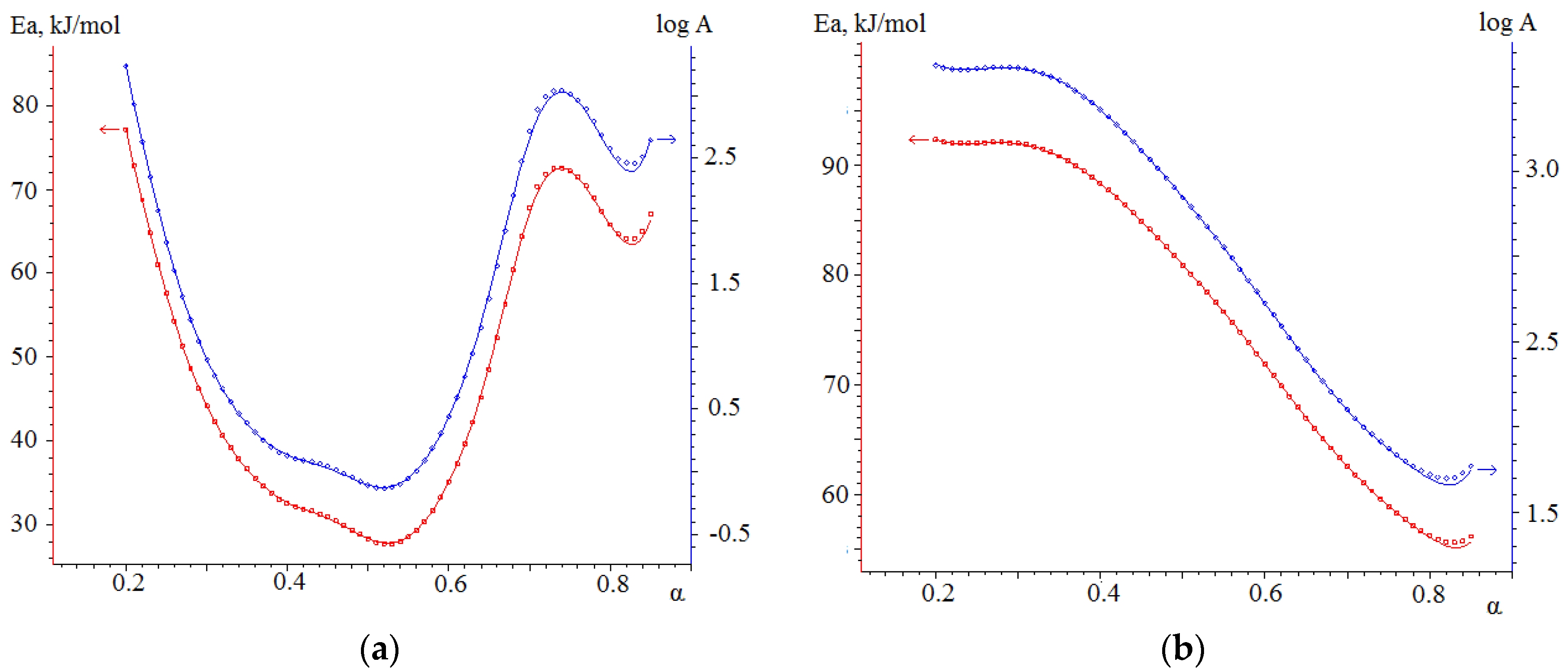
3.4.1. Kinetic Analysis of Individual Fuels

The data of kinetic analysis of combustion of semi-coke and cedar sawdust show the complex nature of this process. Friedman isoconversion curves for the combustion process of sample No. 1 show two closely located peaks (Figure 6a), which characterize the presence of at least two stages occurring at degrees of conversion α = 0–0.7 and α = 0.7–1, corresponding to Stage II and Stage III. However, the stages of thermal decomposition and combustion of coke residue are poorly separated and practically merge at high heating rates.
In the combustion of cedar sawdust, clearly separated stages of thermal decomposition and combustion of coke residue are observed according to TG data. The Friedman model isoconversion curves confirm the thermograms, distinguishing the first stage at α = 0–0.6 and the second at α = 0.6–1 (Figure 6b).
The implicit separation of stages in semi-coke combustion does not show any difference in Ea values for thermal decomposition and ignition stages. Data on the values of activation energy and pre-exponential multipliers calculated by Friedman and Ozawa–Flynn–Wall models using NETZSCH Thermokinetics software for semi-coke combustion are presented in (Figure 7a and 7b), respectively.
The values of activation energy and pre-exponential multiplier for the combustion reaction of cedar sawdust calculated by Friedman and Ozawa–Flynn–Wall models are shown in (Figure 7c,d).
The averaged values of Ea of the combustion process of initial combustibles are presented in Table 6.
The obtained data of activation energy for the semi-coke combustion process insignificantly differ from those for the combustion of Kansko-Achinsk brown coal [38], which is the source of raw material for the analyzed sample No. 1. During the combustion of Borodino coal, Stages II and III also proceed almost simultaneously, with the average value of Ea = 38.4 kJ/mol. It should be noted that the obtained average values of the activation energy of combustion of semi-coke are higher than for the original coal, which may be due to the low content of volatile components compared to the original material.
The activation energy values for cedar sawdust combustion significantly exceed similar data for semi-coke combustion, which is an interesting fact since literature data more often indicate the opposite.
Stage III for cellulosic substances usually has a lower value of activation energy compared to Ea of Stage II, associated with a greater heat release at Stage II, which facilitates the combustion process. The calculated data of activation energy on combustion of sample No. 2 confirm this fact; there is a decrease in activation energy during the transition from thermal decomposition to the process of ignition of coke residue, which is confirmed by both calculation methods having a close value.
Relatively high values of the activation energy of Stage II cause a high fraction of the degree of transformation attributable to this stage in the individual fuels combustion process: 0.7 and 0.6 for sample No. 1 and sample No. 2, respectively.

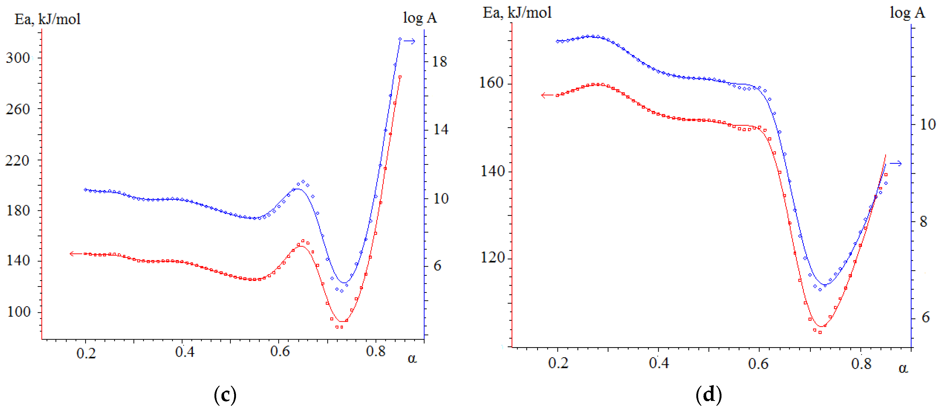
3.4.2. Kinetic Analysis of Co-Combustion

Isoconversion curves of the Friedman model for combustion of the studied mixtures are shown in Figure 8.
As the Friedman model isoconversion curves calculated with the NETZSCH Thermokinetics software show, the mechanism of the combustion process of mixtures is more complicated than for the combustion of initial combustibles: semi-coke and cedar sawdust. In samples No. 3 and No. 4 with high SC content, the profiles of isoconversion curves are similar to each other; from them, it is possible to distinguish three stages occurring at the following degrees of conversion: for sample No. 3, α = 0–0.3; α = 0.3–0.7; α = 0.7–1 and for composition No. 4, α = 0–0.4; α = 0.4–0.7; α = 0.7–1. For composition No. 5, three consecutive stages can also be distinguished: α = 0–0.5; α = 0.5–0.7; and α = 0.7–1.
For the combustion process of all three mixtures, the first stage corresponds to the thermal decomposition of Stage II biomass—sample No. 2, proceeding at a lower temperature for all heating rates than the combustion of semi-coke—sample No. 1.
Stages II and III for samples No. 3 and No. 4 are similar to the profile of the isoconversion curve for combustion of pure semi-coke. These stages also occur at close temperatures and are poorly separated; however, increasing the heating rate does not cause these peaks to merge since the second stage in the isoconversion curves corresponds to the combination of Stage III combustion of cedar sawdust coke residue and Stage II thermal decomposition of semi-coke, which should facilitate the thermal decomposition of sample No. 1 and allow it to complete at a lower temperature. The third stage, occurring at α = 0.7–1, corresponds to the combustion of the coke residue of sample No. 1 and, for mixture No. 3, has a higher intensity compared to mixture No. 4 due to the larger amount of semi-coke present in the sample.
The profile of the isoconversion curve of sample No. 5 is identical to the similar curve for the combustion of cedar sawdust; the difference is Stage 2 for sample No. 5. This stage occurs in a small range of the degree of conversion α = 0.5–0.7, has a small intensity, smooths out with increasing heating rate, and corresponds to the process of thermal decomposition of semi-coke, occurring with a lower Ea than biomass combustion and present in sample No. 5 in a smaller amount than biomass. The third stage for mixture No. 5 combines the stages of the combustion of coke residues and biomass and semi-coke.
It is possible to note an increase in the fraction of the substance participating in the first stage of the combustion process from α = 0.3 to α = 0.5 with increasing biomass fraction in the mixtures, which is explained by the large contribution to the thermal decomposition reaction of sample No. 2 with the highest Ea value.
The values of activation energy and pre-exponential multiplier calculated by NETZSCH Thermokinetics software using Friedman and Ozawa–Flynn–Wall models for the combustion reaction of mixtures are shown in (Figure 9).
The averaged values of activation energy for different stages of combustion of the mixtures are presented in Table 7.
The activation energy of the first stage of combustion of sample No. 3, corresponding to the thermal decomposition of cedar sawdust, has the same value as for the pure initial combustible sample No. 2 for both calculation methods; also, there is a consistency of data on the values of Ea for the third stage relating to the combustion of coke residue of sample No. 1 (Table 6). It follows that these stages are individual stages of the combustion process of samples No. 1 and No. 2 and do not interact with each other when co-combusted at composition semi-coke 75% + cedar sawdust 25%.
The calculated Ea values for the second stage combining simultaneous combustion of biomass coke residue and thermal decomposition of semi-coke show different values obtained by different methods, but in both cases, there is a tendency to decrease Ea during the combustion of coke residue of sample No. 2 due to the presence of a large amount of semi-coke in the system, the activation energy of thermal decomposition of which is much lower than for Stage III of the cedar sawdust combustion process.
During combustion of sample No. 4, containing the same amount of semi-coke and cedar sawdust, the calculated values of Ea for the degrees of transformation α = 0–0.4 are similar in value to the data for samples No. 3 and No. 2, which indicate Stage II thermal decomposition of mixture No. 2, occurring at this stage of combustion and the lack of influence of semi-coke on this process. For the subsequent stages of combustion of sample No. 4, the Friedman model describes the combustion process similarly to sample No. 3: the second stage has a reduced value of Ea due to the combined occurrence of Stage III of sample No. 2 and Stage II of sample No. 1; an increase in the activation energy for the degree of transformation α = 0.7–1, related to the burnout of the coke residue of sample No. 1, but with a higher value than for pure sample No. 1, indicating the influence of biomass additives on this process. It should be noted that these stages proceed with a higher Ea value than mixture No. 3 due to the larger amount of biomass having higher activation energy values. The OFW method shows close results to the Friedman model for stages 1 and 3, but the calculated Ea values for the second stage do not show a decrease in activation energy relative to the first stage, although the energy curve profile (Figure 9d) has a well-defined minimum at α ≈ 0.5, which corresponds to a similar relationship calculated by the Friedman method. The high values of Ea in the OFW method are compensated by higher values of the pre-exponential multiplier, differing by a factor of 10 compared to the Friedman method.
For sample No. 5, the large amount of biomass present in the mixture and burning with a high Ea value allows describing the energetics of the process with values close to the Ea values of the combustion of pure sample No. 2. The very narrow range of the degree of transformation of the second stage, related to the thermal decomposition of sample No. 1 at α = 0.5–0.7 does not allow us to calculate a significant decrease in activation energy for this stage; however, at the degree of transformation α = 0.6, the Friedman method and the OFW method show minimum and very close values of Ea equal to 95.0 and 96.7 kJ/mol, respectively.
The kinetic analysis determined that the activation energy values for the combustion process of the initial substances are very different. Sample No. 2 burns with a higher value of activation energy than sample No. 1. The combustion of the mixtures of initial fuels for compositions No. 3 and No. 4 are more described by the combustion energy of the initial semi-coke and sample No. 5 by the combustion energy of cedar sawdust. For all mixtures, Stage II combustion of cedar sawdust has a significantly separated stage by temperature and cannot participate in the synergy of the combustion process of mixtures. As the amount of biomass in the mixtures increases, there is a successive overlap of Stage III combustion of the coke residue of sample No. 2 and Stage II thermal decomposition of fuel No. 1 in samples No. 3 and No. 4 and Stage III thermal decomposition of both No. 1 and No. 2 in sample No. 5. A noticeable decrease in Ea occurs with the symbiosis of Stage III combustion of sample No. 2 and Stage II of sample No. 1 in samples No. 3 and No. 4, but the low presence of volatile components in sample No. 3 does not reveal a clear synergistic effect for this composition.

4. Conclusions

In this paper, we have researched the combustion process of semi-coke obtained in the process of gasification of brown coal at temperatures of 700–900 °C, cedar sawdust, and their mixtures using a thermogravimetric method at heating rates of 10, 20, and 30 °C min−1 in an oxidizing environment. The main results of the work are as follows:
(1)
The obtained semi-coke has a low volatile matter content of 8.4%, which may have an adverse effect on its combustion in the boiler furnace, and a high calorific value of 32.1 MJ/kg. Adding biomass with high volatile matter content (80.2%) to semi-coke will increase the volatile matter content of the mixture, which will have a positive effect on the combustion of the mixtures.
(2)
According to the results of the thermal analysis, the main combustion characteristics were established for the investigated fuels and mixtures. The ignition temperature of semi-coke is 38% higher than that of biomass, the burnout temperature is 45% higher, and the combustion index is five times lower than that of biomass. At least 50% of biomass should be added to semi-coke; there is a 7% increase in combustion index compared to semi-coke; further increase in biomass content in the mixture will increase the combustion index, which will have a positive effect on the combustion of the mixture.
(3)
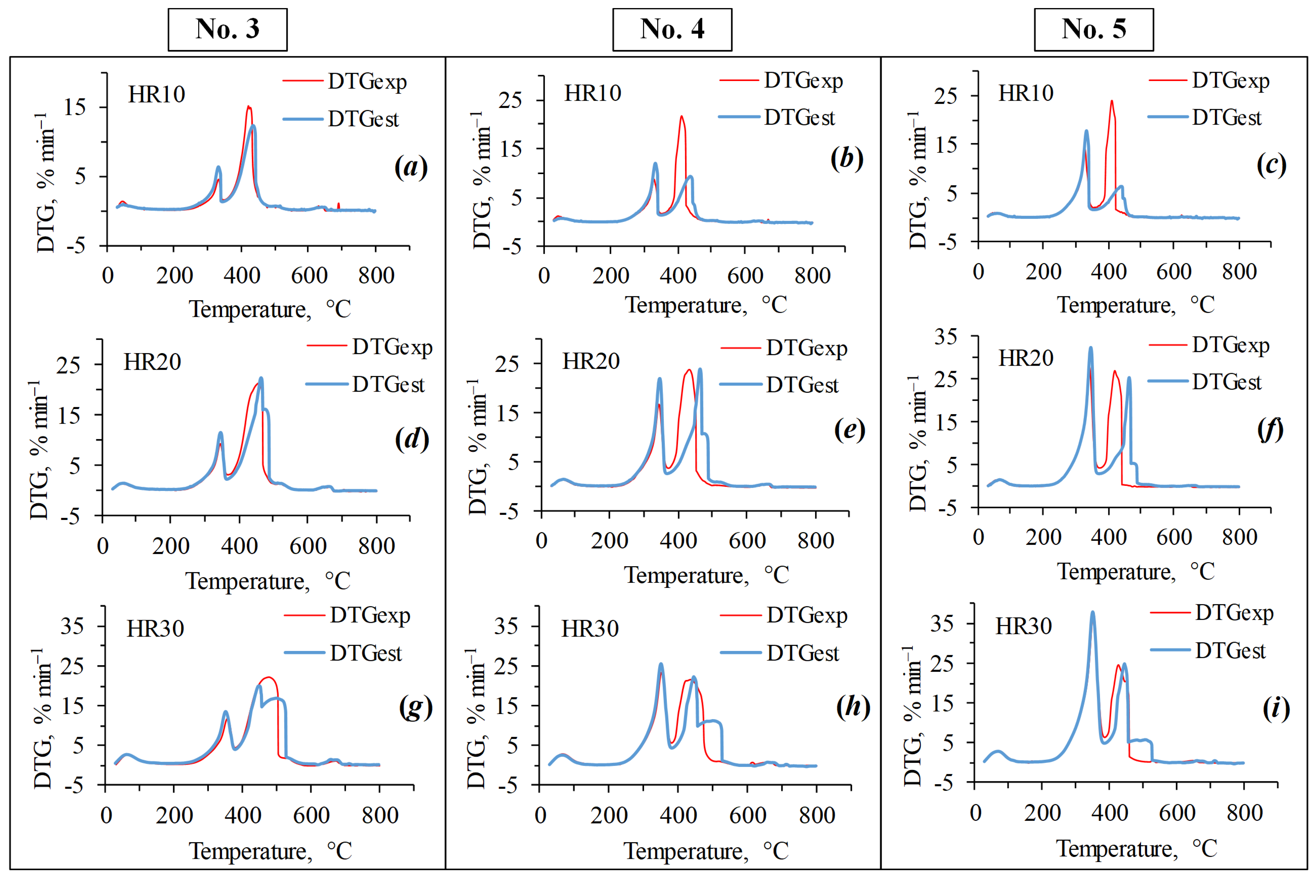
Both positive and negative synergetic interactions between mixture components are observed during the combustion of mixtures. Synergetic effects reducing the maximum heating rate at all heating rates are mainly observed in the combustion of biomass volatiles. Synergetic effects positively influencing the combustion process were observed in the combustion of biomass coke residue and semi-coke. There is no dependence between the heating rate of the studied fuels and the synergetic effects occurring between the components of the mixtures influencing the combustion process.
(4)
The results obtained in the determination of kinetic parameters show higher activation energy values for biomass combustion (113.5 kJ/mol) compared to semi-coke (76.5 kJ/mol). The kinetic analysis found that the combustion of mixtures overlaps different stages of combustion processes of individual fuels, resulting in lower activation energy values for such joint processes. Thus, the mixture based on 75% semi-coke and 25% cedar sawdust has the lowest activation energy value, high values of the pre-exponential multiplier, sufficient amount of volatile components, and, in our case, is a composition with a large synergetic effect.

Author Contributions

Conceptualization, A.Z. and L.I.; methodology, A.Z.; software, A.Z.; validation, A.Z., A.S., and S.C.; formal analysis, A.Z.; investigation, A.Z.; resources, A.Z.; data curation, A.Z.; writing—original draft preparation, A.Z.; writing—review and editing, I.G.; visualization, T.P.; supervision, Y.Z. All authors have read and agreed to the published version of the manuscript.

Funding

This research received no external funding.

Data Availability Statement

The data presented in this study are available upon request from the corresponding author. The data are not publicly available due to confidentiality reasons.

Conflicts of Interest

The authors declare no conflicts of interest.

References

  1. Gür, T.M. Carbon Dioxide Emissions, Capture, Storage and Utilization: Review of Materials Processes and Technologies. Prog. Energy Combust. Sci. 2022, 89, 100965. [Google Scholar] [CrossRef]
  2. Overland, I.; Loginova, J. The Russian coal industry in an uncertain world: Finally pivoting to Asia? Energy Res. Soc. Sci. 2023, 102, 103150. [Google Scholar] [CrossRef]
  3. Baxter, L. Biomass-Coal Cofiring: An Overview of Technical Issues. Green Energy Technol. 2011, 28, 43–73. [Google Scholar] [CrossRef]
  4. Variny, M.; Varga, A.; Rimár, M.; Janošovský, J.; Kizek, J.; Lukáč, L.; Jablonský, G.; Mierka, O. Advances in biomass co-combustion with fossil fuels in the European context: A review. Processes 2021, 9, 100. [Google Scholar] [CrossRef]
  5. Pazheri, F.R.; Othman, M.F.; Malik, N.H. A review on global renewable electricity scenario. Renew. Sust. Energ. Rev. 2014, 31, 835–845. [Google Scholar] [CrossRef]
  6. Sahu, S.G.; Chakraborty, N.; Sarkar, P. Coal-biomass co-combustion: An overview. Renew. Sust. Energ. Rev. 2014, 39, 575–586. [Google Scholar] [CrossRef]
  7. Al-Mansour, F.; Zuwala, J. An evaluation of biomass co-firing in Europe. Biomass Bioenergy 2010, 34, 620–629. [Google Scholar] [CrossRef]
  8. Ding, G.; He, B.; Yao, H.; Cao, Y.; Su, L.; Duan, Z. Co-combustion behaviors of municipal solid waste and low-rank coal semi-coke in air or oxygen/carbon dioxide atmospheres. J. Therm. Anal. Calorim. 2021, 143, 619–635. [Google Scholar] [CrossRef]
  9. Wang, P.; Wang, C.; Wang, C.; Du, Y.; Che, D. Experimental investigation on co-combustion characteristics of semi-coke and coal: Insight into synergy and blending method. Process Saf. Environ. Prot. 2023, 175, 290–302. [Google Scholar] [CrossRef]
  10. Zhou, H.; Wang, K.; Ni, J.; Wu, J.; Ji, P.; Zeng, W.; Li, J.; Zhao, B.; Kou, M. Numerical simulation of co-combustion characteristics of semicoke and coke breeze in an ironmaking blast furnace. Fuel 2023, 335, 127113. [Google Scholar] [CrossRef]
  11. Liu, Y.; Tan, W.; Liang, S.; Pan, X. Study on the co-combustion behavior of semi-coke and typical biomass: Combustion, NO emission and ash characteristics analysis. Fuel 2024, 358, 130068. [Google Scholar] [CrossRef]
  12. Liu, H.-P.; Liang, W.-X.; Qin, H.; Wang, Q. Synergy in co-combustion of oil shale semi-coke with torrefied cornstalk. Appl. Therm. Eng. 2016, 109, 653–662. [Google Scholar] [CrossRef]
  13. Qi, H.; Sun, R.; Peng, J.; Meng, X.; Cao, Z.; Wang, Z.; Ren, X.; Yuan, M.; Zhang, L.; Ding, S. Experimental investigation on the ignition and combustion characteristics of pyrolyzed char and bituminous coal blends. Fuel 2020, 281, 118732. [Google Scholar] [CrossRef]
  14. Qin, H.; Wang, W.; Liu, H.; Zhang, L.; Wang, Q.; Shi, C.; Yao, K. Thermal behavior research for co-combustion of furfural residue and oil shale semi-coke. Appl. Therm. Eng. 2017, 120, 19–25. [Google Scholar] [CrossRef]
  15. Zheng, S.; Hu, Y.; Wang, Z.; Cheng, X. Experimental investigation on ignition and burnout characteristics of semi-coke and bituminous coal blends. J. Energy Inst. 2020, 93, 1373–1381. [Google Scholar] [CrossRef]
  16. Zhang, J.; Jia, X.; Wang, C.; Zhao, N.; Wang, P.; Che, D. Experimental investigation on combustion and NO formation characteristics of semi-coke and bituminous coal blends. Fuel 2019, 247, 87–96. [Google Scholar] [CrossRef]
  17. Hu, L.; Zhang, Y.; Chen, D.; Fang, J.; Zhang, M.; Wu, Y.; Zhang, H.; Li, Z.; Lyu, J. Experimental study on the combustion and NOx emission characteristics of a bituminous coal blended with semi-coke. Appl. Therm. Eng. 2019, 160, 113993. [Google Scholar] [CrossRef]
  18. Zhao, R.; Qin, J.; Chen, T.; Wu, J. TG-FTIR study on co-combustion of bituminous coal semicoke and lignite. J. Therm. Anal. Calorim. 2022, 147, 1849–1858. [Google Scholar] [CrossRef]
  19. ISO 11722:1999; Solid Mineral Fuels—Hard Coal—Determination of Moisture in the General Analysis Test Sample by Drying in Nitrogen. International Organization for Standardization: Geneva, Switzerland, 1999.
  20. ISO 1171:2010; Solid Mineral Fuel—Determination of Ash. International Organization for Standardization: Geneva, Switzerland, 2010.
  21. ISO 562:2010; Hard Coal and Coke—Determination of Volatile Matter. International Organization for Standardization: Geneva, Switzerland, 2010.
  22. ISO 1928:2009; Solid Mineral Fuels—Determination of Gross Calorific Value by the Bomb Calorimetric Method and Calculation of Net Calorific Value. International Organization for Standardization: Geneva, Switzerland, 2009.
  23. ASTM D5373-14e1; Standard Test Methods for Determination of Carbon, Hydrogen and Nitrogen in Analysis Samples of Coal and Carbon in Analysis Samples of Coal and Coke. ASTM International: West Conshohocken, PA, USA, 2014.
  24. Oladejo, J.M.; Adegbite, S.; Pang, C.H.; Liu, H.; Parvez, A.M.; Wu, T. A novel index for the study of synergistic effects during the co-processing of coal and biomass. Appl. Energy. 2017, 188, 215–225. [Google Scholar] [CrossRef]
  25. Moon, C.; Sung, Y.; Ahn, S.; Kim, T.; Choi, G.; Kim, D. Effect of blending ratio on combustion performance in blends of biomass and coals of different ranks. Exp. Therm. Fluid Sci. 2013, 47, 232–240. [Google Scholar] [CrossRef]
  26. Liu, Z.; Quek, A.; Hoekman, S.K.; Srinivasan, M.P.; Balasubramanian, R. Thermogravimetric investigation of hydrochar-lignite co-combustion. Bioresour. Technol. 2012, 123, 646–652. [Google Scholar] [CrossRef] [PubMed]
  27. Zhuikov, A.V.; Glushkov, D.O.; Kuznetsov, P.N.; Grishina, I.I.; Samoilo, A.S. Ignition of two-component and three-component fuel mixtures based on brown coal and char under slow heating conditions. J. Therm. Anal. Calorim. 2022, 147, 11965–11976. [Google Scholar] [CrossRef]
  28. Wang, C.; Wang, F.; Yang, Q.; Liang, R. Thermogravimetric studies of the behavior of wheat straw with added coal during combustion. Biomass Bioenergy 2009, 33, 50–56. [Google Scholar] [CrossRef]
  29. Raza, M.; Abu-Jdayil, B.; Al-Marzouqi, A.H.; Inayat, A. Inayat Kinetic and thermodynamic analyses of date palm surface fibers pyrolysis using Coats-Redfern method. Renew. Energy 2022, 183, 67–77. [Google Scholar] [CrossRef]
  30. Isaac, K.; Bada, S.O. The co-combustion performance and reaction kinetics of refuse derived fuels with South African high ash coal. Heliyon 2020, 6, e03309. [Google Scholar] [CrossRef]
  31. Yuan, Y.; Zuo, H.; Wang, J.; Gao, Y.; Xue, Q.; Wang, J. Co-combustion behavior, kinetic and ash melting characteristics analysis of clean coal and biomass pellet. Fuel 2022, 324, 124727. [Google Scholar] [CrossRef]
  32. Armakan, S.; Civan, M.; Yurdakul, S. Determining co-combustion characteristics, kinetics and synergy behaviors of raw and torrefied forms of two distinct types of biomass and their blends with lignite. J. Therm. Anal. Calorim. 2022, 147, 12855–12869. [Google Scholar] [CrossRef]
  33. Friedman, H.L. Kinetics of thermal degradation of char-forming plastics from thermogravimetry. Application to a phenolic plastic. J. Polym. Sci. Part C Polym. Symp. 1964, 6, 183–195. [Google Scholar] [CrossRef]
  34. Ozawa, T. A New Method of Analyzing Thermogravimetric Data. Bull. Chem. Soc. Japan 1965, 38, 1881–1886. [Google Scholar] [CrossRef]
  35. Flynn, J.H.; Wall, L.A. A quick, direct method for the determination of activation energy from thermogravimetric data. J. Polym. Sci. Part B Polym. Lett. 1966, 4, 323–328. [Google Scholar] [CrossRef]
  36. Doyle, C.D. Estimating isothermal life from thermogravimetric data. J. Appl. Polym. Sci. 1962, 6, 639–642. [Google Scholar] [CrossRef]
  37. Glushkov, D.O.; Zhuikov, A.V.; Nurpeiis, A.E.; Paushkina, K.K.; Kuznechenkova, D.A. Ignition behavior of a mixture of brown coal and biomass during the movement of fine particles in a hot air flow. Fuel 2024, 363, 131010. [Google Scholar] [CrossRef]
  38. Kuznetsov, P.N.; Kuznetsova, L.I.; Bimer, J.; Salbut, P.; Gruber, R.; Brodzki, D. Quantitative relation between the macromolecular characteristics of brown coal and its reactivity in conversion with tetralin. Fuel 1997, 76, 189–193. [Google Scholar] [CrossRef]
Figure 1. Type of fuels under study: (a)—semi-coke; (b)—cedar sawdust.
Energies 17 04963 g001
Figure 2. SEM images: (a)—semi-coke 100×; (b)—semi-coke 500×; (c)—cedar sawdust 100×; (d)—cedar sawdust 200×.
Energies 17 04963 g002
Figure 3. Combustion profiles of semi-coke (No. 1) and cedar sawdust (No. 2): (a)—TG curves at heating rate 10 °C min−1; (b)—DTG curves at heating rate 10 °C min−1; (c)—TG curves at heating rate 20 °C min−1; (d)—DTG curves at heating rate 20 °C min−1; (e)—TG curves at heating rate 30 °C min−1; (f)—DTG curves at heating rate 30 °C min−1.
Energies 17 04963 g003
Figure 4. Thermal curves of processes occurring during the heating of solid fuel mixtures: (a)—TG curves at heating rate 10 °C min−1; (b)—DTG curves at heating rate 10 °C min−1; (c)—TG curves at heating rate 20 °C min−1; (d)—DTG curves at heating rate 20 °C min−1; (e)—TG curves at heating rate 30 °C min−1; (f)—DTG curves at heating rate 30 °C min−1.
Energies 17 04963 g004
Figure 5. Comparison of DTG curve profiles obtained by experimental (DTGexp) and calculated (DTGest) methods: (a)—mixture No. 3 at HR 10; (b)—mixture No. 4 at HR 10; (c)—mixture No. 5 at HR 10; (d)—mixture No. 3 at HR 20; (e)—mixture No. 4 at HR 20; (f)—mixture No. 5 at HR 20; (g)—mixture No. 3 at HR 30; (h)—mixture No. 4 at HR 30; (i)—mixture No. 5 at HR 30.
Energies 17 04963 g005
Figure 6. Friedman method isoconversion curves for combustion of semi-coke (sample No. 1) (a) and cedar sawdust (sample No. 2) (b). Black line—lines connecting points with the same degree of transformation (α) on isoconversion curves with different heating rates.
Energies 17 04963 g006
Figure 7. Dependence of Ea (red line) and A values on α (blue line) for semi-coke combustion: (a)—Friedman model, (b)—OFW model and for cedar sawdust combustion, (c)—Friedman model, (d)—OFW model.
Energies 17 04963 g007aEnergies 17 04963 g007b
Figure 8. Isoconversion curves of the Friedman model for the combustion process of mixtures: (a)—No. 3, (b)—No. 4, (c)—No. 5. Black line—lines connecting points with the same degree of transformation (α) on isoconversion curves with different heating rates.
Energies 17 04963 g008
Figure 9. Dependence of Ea (red line) and A values on α (blue line): sample No. 3. (a)—Friedman model, (b)—OFW model; sample No. 4 (c)—Friedman model, (d)—OFW model; sample No. 5 (e)—Friedman model, (f)—OFW model.
Energies 17 04963 g009aEnergies 17 04963 g009b
Table 1. Proximate and ultimate analysis of tested samples.
No.Proximate Analysis/%Ultimate Analysis/%
MCaAdVCdafHHVCdafHdafNdafSdafOdaf
%%%MJ/kg%%%%%
10.89.18.432.191.22.42.20.24.0
26.40.280.219.251.35.40.343.0
Notes: a—analytical state; d—a dry state; daf—a dry, ash-free state.
Table 2. Ash analysis of samples.
Oxides, %No.1—Semi-CokeNo.2—Cedar Sawdust
SiO250.510.5
Al2O310.01.3
Fe2O313.71.1
CaO23.055.1
MgO4.54.0
TiO20.10.1
Na2O0.20.6
K2O0.319.2
SO36.02.3
P2O50.043.1
ZnO0.050.9
Cl0.010.3
MnO0.051.5
Table 3. Temperature ranges of the main combustion stages of individual fuels and fuel mixtures.
SamplesHR, °C min−1Temperature Interval Stage II, °CStage II, minTemperature Interval Stage III, °CStage III, minBurning, min
No. 110295–4059.5406–65326.536.0
20310–4355.1436–67213.118.2
30290–4404.2441–6909.213.4
No. 210201–2999.4300–46116.726.1
20202–3115.2312–4698.213.4
30202–3183.8319–4584.78.5
No. 310240–34921.2350–64430.051.2
20230–4018.0402–66914.022.0
30240–4065.1407–6899.915.0
No. 410233–3016.6302–66937.243.8
20220–3134.6314–66517.722.3
30229–3182.9319–67512.014.9
No. 510216–3018.0302–62533.141.1
20204–3115.4312–4567.412.8
30206–3163.5317–4895.99.4
Table 4. Combustion performance of mixed fuel under different mixing ratios.
SamplesHR, °C min−1RDTG,
% min–1
Ti, °CTDTG, °CTb, °CS × 10–7,
min–2 °C–3
No. 110295–4059.5406–653 26.536.0
20310–4355.1436–67213.118.2
30290–4404.2441–6909.213.4
No. 210201–299 9.4300–46116.726.1
20202–3115.2312–4698.213.4
30202–3183.8319–4584.78.5
No. 310240–349 21.2350–64430.051.2
20230–4018.0402–66914.022.0
30240–4065.1407–6899.915.0
No. 410233–3016.6302–669 37.243.8
20220–3134.6314–66517.722.3
30229–3182.9319–67512.014.9
No. 510216–3018.0302–625 33.141.1
20204–3115.4312–4567.412.8
30206–3163.5317–4895.99.4
Table 5. DTGexp and DTGest results at different heating rates and stages.
BlendsStage IIStage III
DTGexp, % min−1DTGest, % min−1DTGexp, % min−1DTGest, % min−1
Heating rate 10 °C min−1No. 34.56.415.112.4
No. 48.812.121.79.4
No. 514.317.724.16.4
Heating rate 20 °C min−1No. 39.411.621.522.5
No. 416.822.023.724.0
No. 528.132.527.225.4
Heating rate 30 °C min−1No. 311.813.622.320.2
No. 423.425.721.522.4
No. 537.737.824.624.8
Table 6. Values of Ea and A for different stages of combustion of initial combustibles.
Friedman ModelOFW ModelFriedman ModelOFW Model
Ea, kJ/molEa, kJ/molEa, kJ/molEa, kJ/mol
Stage IIn/an/a140.1155.1
Stage IIIn/an/a113.5120.9
average63.6 76.5n/an/a
Table 7. Values of Ea for different stages of combustion of mixtures.
SampleTransformation DegreeFriedman Model
Ea, kJ/mol
OFW Model
Ea, kJ/mol
No. 3α = 0–0.3141.7157.0
α = 0.3–0.758.8107.8
α = 0.7–187.177.9
No. 4α = 0–0.4176.1159.0
α = 0.4–0.767.4179.4
α = 0.7–1120.0114.0
No. 5α = 0–0.5166.6165.0
α =0.5–0.7164.5143.2
α = 0.7–1104.5158.9
Disclaimer/Publisher’s Note: The statements, opinions and data contained in all publications are solely those of the individual author(s) and contributor(s) and not of MDPI and/or the editor(s). MDPI and/or the editor(s) disclaim responsibility for any injury to people or property resulting from any ideas, methods, instructions or products referred to in the content.

