
Torque Ripple and Electromagnetic Vibration Suppression of Fractional Slot Distributed Winding ISG Motors by Rotor Notching and Skewing


Abstract
:1. Introduction
2. Torque Ripple and Radial EM Force of PMSM
2.1. Torque Ripple
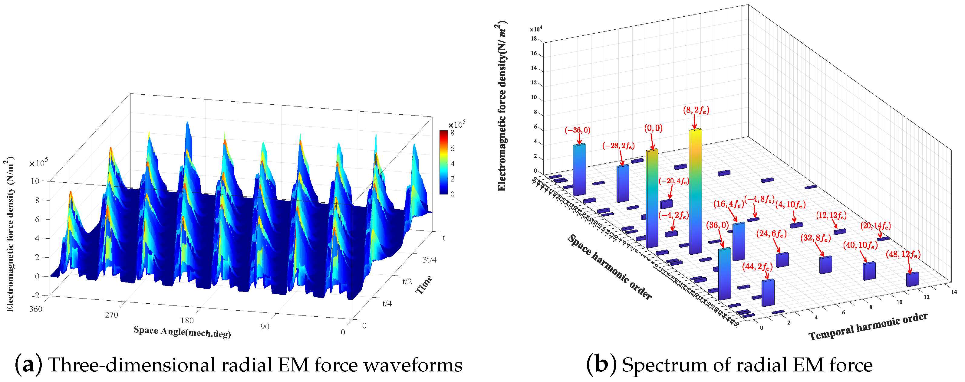
2.2. Radial EM Force of PMSM
3. ISG Motor Model with Rotor Notching and Skewing Configurations
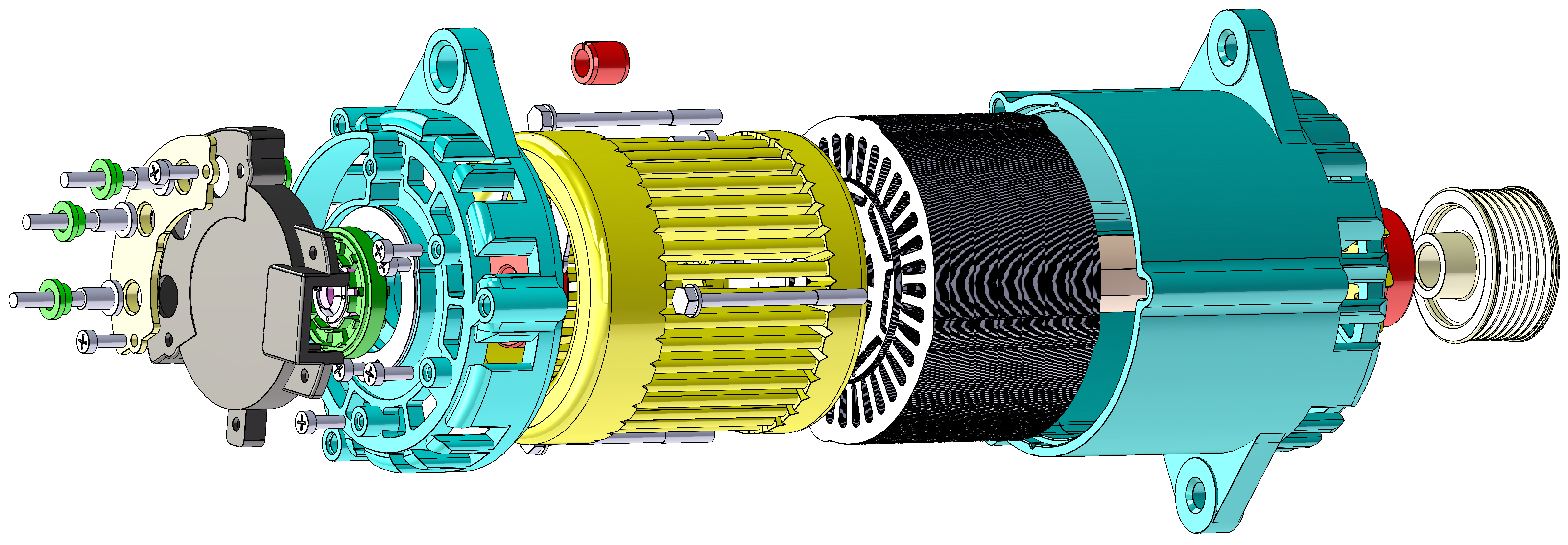
3.1. Initial Design of the ISG Motor
3.2. Rotor Notching Design
3.3. Rotor Skew Design
4. Analysis of Torque Ripple and EM Vibrations
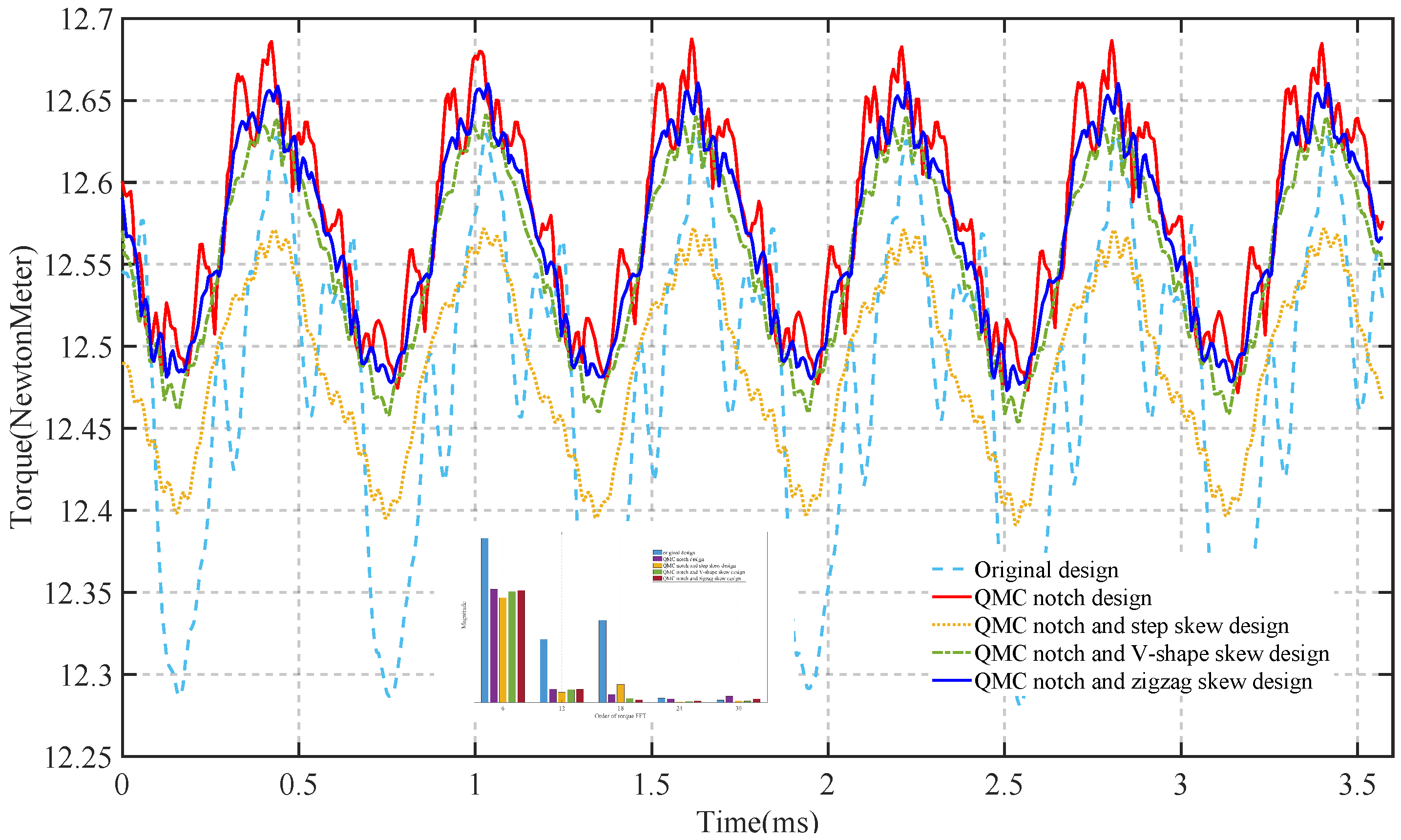
4.1. Analysis of Torque Ripple in ISG Motors
4.2. Analysis of Radial EM Forces in ISG Motors
4.3. Motor Modal Analysis
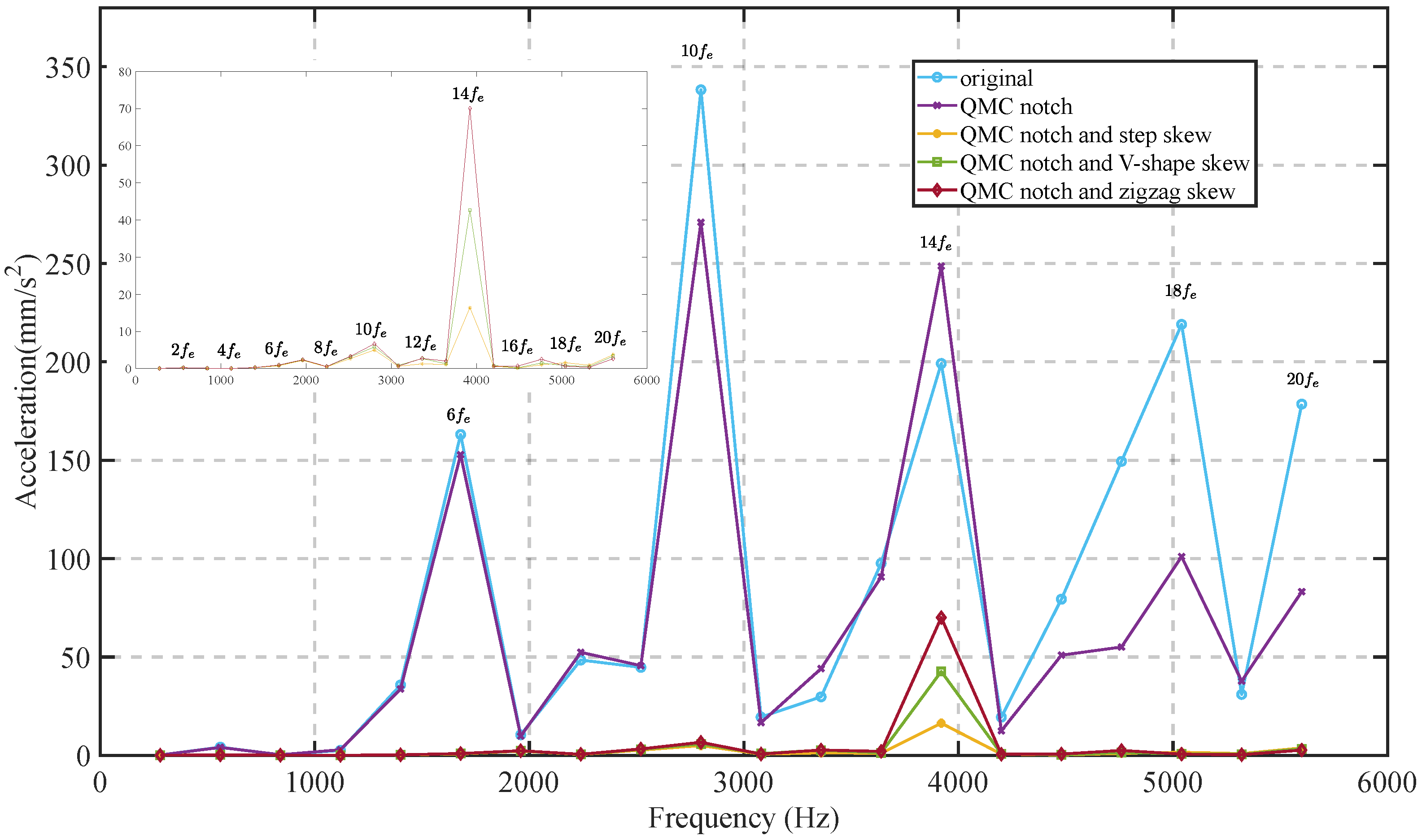
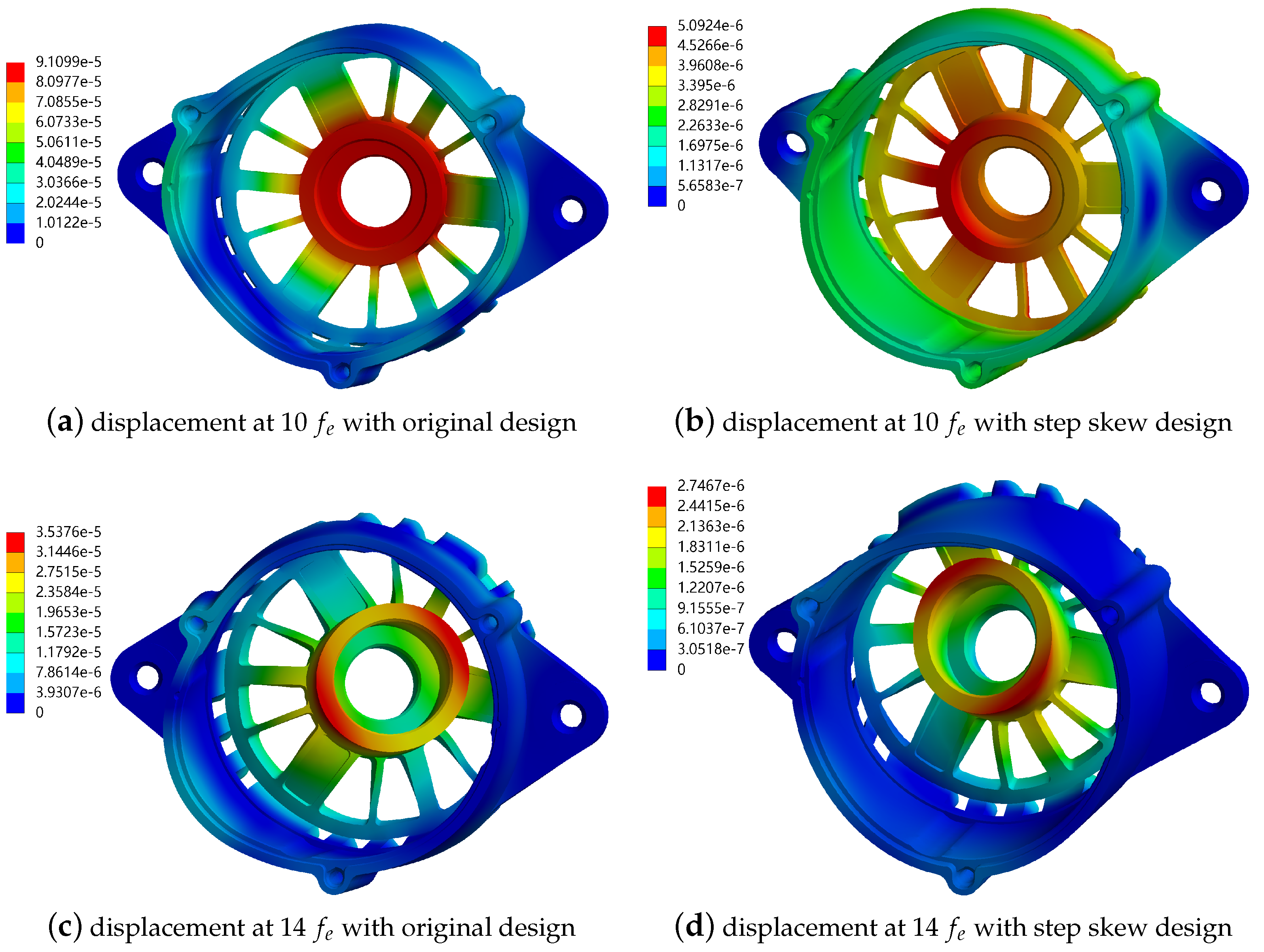
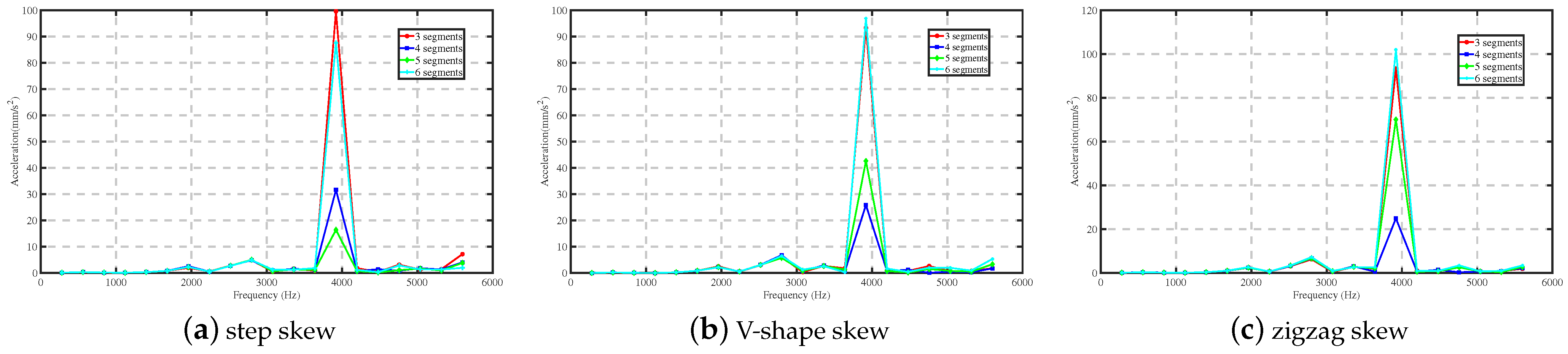
4.4. EM Vibration Response Analysis of ISG Machines
4.5. Result Discussion
5. Conclusions
Author Contributions
Funding
Data Availability Statement
Conflicts of Interest
Abbreviations
| GHGs | greenhouse gases |
| ICEVs | internal combustion engine vehicles |
| HEVs | hybrid electric vehicles |
| EVs | electric vehicles |
| SG | starter/generator |
| ISG | integrated starter and generator |
| PM | permanent magnet |
| PMSMs | permanent magnet synchronous motors |
| IPMSMs | Interior permanent magnet synchronous motors |
| SPMSMs | surface-mounted permanent magnet synchronous motors |
| EM | electromagnetic |
| SS | step skew |
| VS | V-shape skew |
| ZS | zigzag skew |
| MB | notch magnetic bridge notch |
| QMC | notch Q-axis and magnetic bridge notch combination |
| NSGA-II | non-dominated sorting genetic algorithm-II |
| RSS | rotor segmented skewed |
| GCD | greatest common divisor |
| FEA | finite element analysis |
| back-EMF | back-electromotive force |
| FFT | Fast Fourier transform |
| THD | Total harmonic distortion |
References
- Gali, V.; Canha, L.N.; Resener, M.; Ferraz, B.; Varaprasad, M.V. Advanced Technologies in Electric Vehicles: Challenges and Future Research Developments; Elsevier: Amsterdam, The Netherlands, 2024. [Google Scholar]
- Jung, J.; Yeo, S.; Lee, Y.; Moon, S.; Lee, D.J. Factors affecting consumers’ preferences for electric vehicle: A Korean case. Res. Transp. Bus. Manag. 2021, 41, 100666. [Google Scholar] [CrossRef]
- Ehsani, M.; Singh, K.V.; Bansal, H.O.; Mehrjardi, R.T. State of the art and trends in electric and hybrid electric vehicles. Proc. IEEE 2021, 109, 967–984. [Google Scholar] [CrossRef]
- Jeon, S.; Lee, G.S.; Kang, D.W.; Kim, W.H.; Bae, S. Belt-Driven Integrated Starter and Generator Using Planetary Gears for Micro Hybrid Electric Vehicles. IEEE Access 2021, 9, 56201–56213. [Google Scholar] [CrossRef]
- Cheng, M.; Sun, L.; Buja, G.; Song, L. Advanced electrical machines and machine-based systems for electric and hybrid vehicles. Energies 2015, 8, 9541–9564. [Google Scholar] [CrossRef]
- Vlachou, V.I.; Sakkas, G.K.; Xintaropoulos, F.P.; Pechlivanidou, M.S.C.; Kefalas, T.D.; Tsili, M.A.; Kladas, A.G. Overview on Permanent Magnet Motor Trends and Developments. Energies 2024, 17, 538. [Google Scholar] [CrossRef]
- Peng, C.; Wang, D.; Wang, B.; Li, J.; Xu, C.; Wang, X. Torque ripple and electromagnetic vibration suppression in permanent magnet synchronous motor using segmented rotor with different pole widths. IEEE Trans. Magn. 2022, 58, 1–5. [Google Scholar] [CrossRef]
- Jang, H.; Kim, H.; Liu, H.C.; Lee, H.J.; Lee, J. Investigation on the torque ripple reduction method of a hybrid electric vehicle motor. Energies 2021, 14, 1413. [Google Scholar] [CrossRef]
- Zhu, S.; Zhao, W.; Ji, J.; Liu, G.; Lee, C.H. Generation Mechanism and Suppression Measure of Electromagnetic Vibration in Permanent Magnet Synchronous Machine: A Review. IEEE Trans. Transp. Electrif. 2024. early access. [Google Scholar] [CrossRef]
- Sun, X.; Shi, Z.; Lei, G.; Guo, Y.; Zhu, J. Multi-objective design optimization of an IPMSM based on multilevel strategy. IEEE Trans. Ind. Electron. 2020, 68, 139–148. [Google Scholar] [CrossRef]
- Fatemi, A.; Nehl, T.W.; Yang, X.; Hao, L.; Gopalakrishnan, S.; Omekanda, A.M.; Namuduri, C.S. Design optimization of an electric machine for a 48-V hybrid vehicle with comparison of rotor technologies and pole-slot combinations. IEEE Trans. Ind. Appl. 2020, 56, 4609–4622. [Google Scholar] [CrossRef]
- Hwang, M.H.; Han, J.H.; Kim, D.H.; Cha, H.R. Design and analysis of rotor shapes for IPM motors in EV power traction platforms. Energies 2018, 11, 2601. [Google Scholar] [CrossRef]
- Shah, S.H.; Wang, X.; Abubakar, U.; Wang, L.; Gao, P. Investigation of noise and vibration characteristics of an IPMSM with modular-type winding arrangements having three-phase sub-modules for fault-tolerant applications. IET Electr. Power Appl. 2022, 16, 248–266. [Google Scholar] [CrossRef]
- Wan, X.; Yang, S.; Li, Y.; Shi, Y.; Lou, J. Minimization of cogging torque for V-type IPMSM by the asymmetric auxiliary slots on the rotor. IEEE Access 2022, 10, 89428–89436. [Google Scholar] [CrossRef]
- Sun, K.; Tian, S. Multiobjective optimization of IPMSM with FSCW applying rotor notch design for torque performance improvement. IEEE Trans. Magn. 2022, 58, 1–9. [Google Scholar] [CrossRef]
- Moon, J.H.; Kang, D.W. Torque ripple and cogging torque reduction method of IPMSM using asymmetric shoe of stator and notch in stator. J. Electr. Eng. Technol. 2022, 17, 3465–3471. [Google Scholar] [CrossRef]
- Hwang, M.H.; Lee, H.S.; Cha, H.R. Analysis of torque ripple and cogging torque reduction in electric vehicle traction platform applying rotor notched design. Energies 2018, 11, 3053. [Google Scholar] [CrossRef]
- Cheng, Y.; Ding, L.; Zhao, T.; Cui, S. Design and Optimization of Electric Vehicle Traction Motor Considering Rotor Topology and Manufacturing Uncertainty. IEEE Trans. Ind. Electron. 2023, 71, 5034–5044. [Google Scholar] [CrossRef]
- Mao, J.; Huang, J.; Xu, X.; Zheng, J.; Zhang, X. Design and Analysis of Interior Permanent Magnet Motor with Magnetic Isolation and Heat Dissipation Integrated Auxiliary slot. IEEE Access 2023, 11, 93004–93011. [Google Scholar] [CrossRef]
- Ocak, O.; Aydin, M. An innovative semi-FEA based, variable magnet-step-skew to minimize cogging torque and torque pulsations in permanent magnet synchronous motors. IEEE Access 2020, 8, 210775–210783. [Google Scholar] [CrossRef]
- Peng, C.; Wang, D.; Wang, B.; Li, J.; Wang, C.; Wang, X. Different Rotor Segmented Approaches for Electromagnetic Vibration and Acoustic Noise Mitigation in Permanent Magnet Drive Motor: A Comparative Study. IEEE Trans. Ind. Electron. 2023, 71, 1223–1233. [Google Scholar] [CrossRef]
- Wang, D.; Peng, C.; Li, J.; Wang, C. Comparison and experimental verification of different approaches to suppress torque ripple and vibrations of interior permanent magnet synchronous motor for EV. IEEE Trans. Ind. Electron. 2022, 70, 2209–2220. [Google Scholar] [CrossRef]
- Wang, S.; Hong, J.; Sun, Y.; Cao, H. Effect comparison of zigzag skew PM pole and straight skew slot for vibration mitigation of PM brush DC motors. IEEE Trans. Ind. Electron. 2019, 67, 4752–4761. [Google Scholar] [CrossRef]
- Wang, S.; Li, H. Effects of rotor skewing on the vibration of permanent magnet synchronous motors with elastic-plastic stator. IEEE Trans. Energy Convers. 2021, 37, 87–96. [Google Scholar] [CrossRef]
- Dai, Y.; Lee, D.-W.; Joung, H.-K.; Lee, H.-J. Optimization on torque ripple performance in isg motors with fractional slot distributed windings and rotor notching. IEEE Access 2024, 12, 123872–123882. [Google Scholar] [CrossRef]
- Zou, J.; Xu, Y.; Lan, H.; Xu, C. Analysis and Suppression of Electromagnetic Vibration of Permanent Magnet Synchronous Machine; National Defense Industry Press: Beijing, China, 2023; pp. 80–82. [Google Scholar]
- Fang, H.; Li, D.; Qu, R.; Yan, P. Modulation effect of slotted structure on vibration response in electrical machines. IEEE Trans. Ind. Electron. 2018, 66, 2998–3007. [Google Scholar] [CrossRef]
- Zhou, X.; Zhu, X.; Xiang, Z.; Fan, D.; Xu, L.; Zhu, T. Harmonic-oriented design and vibration characteristic suppression for interior permanent magnet motors. IEEE Trans. Ind. Electron. 2023, 71, 1246–1256. [Google Scholar] [CrossRef]
- He, S.; Zhang, P.; Muir, M.; Koch, B. Rotor Optimization to Reduce Electric Motor Noise. SAE Int. J. Adv. Curr. Pract. Mobil. 2023, 6, 39–47. [Google Scholar]
- Wang, X. Permanent Magnet Motor, 3rd ed.; China Electric Power Press: Beijing, China, 2023; pp. 87–95. [Google Scholar]
- Deng, W.; Zuo, S. Electromagnetic vibration and noise of the permanent-magnet synchronous motors for electric vehicles: An overview. IEEE Trans. Transp. Electrif. 2018, 5, 59–70. [Google Scholar] [CrossRef]
- Gieras, J.F.; Wang, C.; Lai, J.C. Noise of Polyphase Electric Motors; CRC press: Boca Raton, FL, USA, 2006; pp. 89–105. [Google Scholar]
- Wang, X.; Sun, X.; Gao, P. Study on the effects of rotor-step skewing on the vibration and noise of a PMSM for electric vehicles. IET Electr. Power Appl. 2020, 14, 131–138. [Google Scholar] [CrossRef]
- Li, D.; Xie, Y.; Cai, W.; Chen, P. Analysis of radial electromagnetic force and vibration characteristics of permanent-magnet-based synchronous motor for vibration management. J. Vib. Eng. Technol. 2024, 12, 2629–2640. [Google Scholar] [CrossRef]


| Homonic Order | Space/Temporal Order | ||||||
|---|---|---|---|---|---|---|---|
| 1 | −2 | 4 | −5 | 7 | −8 | 10 | |
| 1 | |||||||
| 3 | |||||||
| 5 | |||||||
| 7 | |||||||
| 9 | |||||||
| 11 | |||||||
| 13 | |||||||
| 15 | |||||||
| Parameters | Value | Unit |
|---|---|---|
| Stator Outer Diameter | 130 | mm |
| Stator Inner Diameter | 81.4 | mm |
| Rotor Outer Diameter | 80 | mm |
| Rotor Inner Diameter | 30.9375 | mm |
| Air-gap | 0.7 | mm |
| Stack Length | 78 | mm |
| Rate Speed | 4200 | rpm |
| Max Speed | 15,000 | rpm |
| PM Width | 14.44 | mm |
| PW Thickness | 3.5 | mm |
| Phase | 3 | |
| Permanent Magnet | N36Z | |
| Silicon Steel Sheet | 50PN470 |
| Parameter | (°) | (mm) | (°) | (°) | (°) | (mm) |
| Value | 139 | 0.23 | 18.065 | 1.195 | 1.23 | 0.92 |
| Segments Number/Length | SS (deg) | VS (deg) | ZS (deg) |
|---|---|---|---|
| 3/26 (mm) | |||
| 4/19.5 (mm) | |||
| 5/15.6 (mm) | |||
| 6/13 (mm) |
| THD of No-Load Back-EMF (%) | |||
|---|---|---|---|
| Original design | 12.48 | 2.85 | 13.04 |
| QMC notch design | 12.58 | 1.71 | 9.70 |
| QMC notch with SS | 12.49 | 1.45 | 9.31 |
| QMC notch with VS | 12.55 | 1.49 | 9.57 |
| QMC notch with ZS | 12.57 | 1.49 | 9.64 |
| Segments | Notch with SS | Notch with VS | Notch with ZS |
|---|---|---|---|
| 3 | = 12.50 Nm = 1.49% | = 12.55 Nm = 1.64% | = 12.55 Nm = 1.64% |
| 4 | = 12.49 Nm = 1.45% | = 12.56 Nm = 1.60% | = 12.56 Nm = 1.60% |
| 5 | = 12.49 Nm = 1.45% | = 12.55 Nm = 1.49% | = 12.57 Nm = 1.49% |
| 6 | = 12.49 Nm = 1.42% | = 12.56 Nm = 1.51% | = 12.57 Nm = 1.55% |
| Segments | SS | VS | ZS |
|---|---|---|---|
| 3 | = 12.39 Nm = 2.11% | = 12.45 Nm = 2.45% | = 12.45 Nm = 2.45% |
| 4 | = 12.39 Nm = 1.90% | = 12.46 Nm = 2.60% | = 12.46 Nm = 2.60% |
| 5 | = 12.38 Nm = 1.92% | = 12.45 Nm = 2.52% | = 12.46 Nm = 2.64% |
| 6 | = 12.38 Nm = 1.89% | = 12.45 Nm = 2.51% | = 12.47 Nm = 2.66% |
| Time Order | Space Order | Electromagnetic Force Density Amplitude (N/m²) | ||||
|---|---|---|---|---|---|---|
| Original | Notch | Notch with SS | Notch with VS | Notch with ZS | ||
| 0 | 0 | 131,638.13 | 128,180.61 | 127,853.64 | 128,394.58 | 128,301.41 |
| 0 | 36 | 68,078.03 | 66,731.04 | 66,517.37 | 66,260.75 | 66,469.52 |
| 0 | −36 | 68,078.03 | 66,731.04 | 66,517.37 | 66,260.75 | 66,469.52 |
| −4 | 5340.94 | 5185.46 | 5087.87 | 5059.66 | 5103.88 | |
| 8 | 168,268.39 | 162,046.25 | 158,610.26 | 161,456.88 | 161,828.05 | |
| −28 | 48,022.29 | 46,959.22 | 46,368.14 | 46,553.48 | 46,750.13 | |
| 44 | 33,989.96 | 33,254.56 | 32,412.25 | 32,731.30 | 32,989.59 | |
| 16 | 49,143.17 | 46,657.48 | 43,159.87 | 45,775.31 | 46,300.18 | |
| −20 | 9414.52 | 10,174.06 | 9511.67 | 9906.00 | 10,052.87 | |
| 24 | 16,897.49 | 19,245.34 | 16,813.19 | 18,605.81 | 18,985.44 | |
| −4 | 2105.29 | 2814.72 | 2046.35 | 2559.99 | 2708.35 | |
| 32 | 20,699.69 | 21,333.41 | 15,912.21 | 19,812.11 | 20,679.35 | |
| 4 | 4506.94 | 3785.27 | 2390.15 | 3355.33 | 3596.44 | |
| 40 | 21,690.71 | 17,778.95 | 10,830.79 | 15,729.13 | 16,880.03 | |
| 12 | 4233.29 | 3279.49 | 1654.69 | 2763.66 | 3048.51 | |
| 48 | 16,489.92 | 10,271.28 | 4869.42 | 8603.97 | 9526.76 | |
| 20 | 2082.36 | 1761.19 | 645.54 | 1390.30 | 1593.09 | |
| Modal order | 0 | 2 | 3 |
| Modal shape |  | 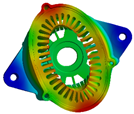 | 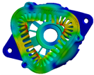 |
| Modal frequency | 8835.2 Hz | 1366.8 Hz | 3842.4 Hz |
| Modal order | 4 | 5 | 6 |
| Modal shape | 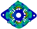 | 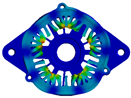 |  |
| Modal frequency | 6175.5 Hz | 7675 Hz | 9094.9 Hz |
| Segments | Torque Ripple (%) | Radial EM Vibration at 14 (mm/s2) | ||||
|---|---|---|---|---|---|---|
| Notch with SS | Notch with VS | Notch with ZS | Notch with SS | Notch with VS | Notch with ZS | |
| 3 | 1.49 | 1.64 | 1.64 | 99.62 | 93.3 | 93.3 |
| 4 | 1.45 | 1.60 | 1.60 | 31.61 | 25.90 | 24.89 |
| 5 | 1.45 | 1.49 | 1.49 | 16.37 | 42.65 | 70.05 |
| 6 | 1.42 | 1.51 | 1.55 | 87.62 | 96.95 | 102.00 |
Disclaimer/Publisher’s Note: The statements, opinions and data contained in all publications are solely those of the individual author(s) and contributor(s) and not of MDPI and/or the editor(s). MDPI and/or the editor(s) disclaim responsibility for any injury to people or property resulting from any ideas, methods, instructions or products referred to in the content. |
© 2024 by the authors. Licensee MDPI, Basel, Switzerland. This article is an open access article distributed under the terms and conditions of the Creative Commons Attribution (CC BY) license (https://creativecommons.org/licenses/by/4.0/).
Share and Cite
Dai, Y.; Lee, H.-J. Torque Ripple and Electromagnetic Vibration Suppression of Fractional Slot Distributed Winding ISG Motors by Rotor Notching and Skewing. Energies 2024, 17, 4964. https://doi.org/10.3390/en17194964
Dai Y, Lee H-J. Torque Ripple and Electromagnetic Vibration Suppression of Fractional Slot Distributed Winding ISG Motors by Rotor Notching and Skewing. Energies. 2024; 17(19):4964. https://doi.org/10.3390/en17194964
Chicago/Turabian StyleDai, Yunfei, and Ho-Joon Lee. 2024. "Torque Ripple and Electromagnetic Vibration Suppression of Fractional Slot Distributed Winding ISG Motors by Rotor Notching and Skewing" Energies 17, no. 19: 4964. https://doi.org/10.3390/en17194964