
Solar Chimney Operation Variant


Abstract
:1. Introduction
2. Materials and Methods
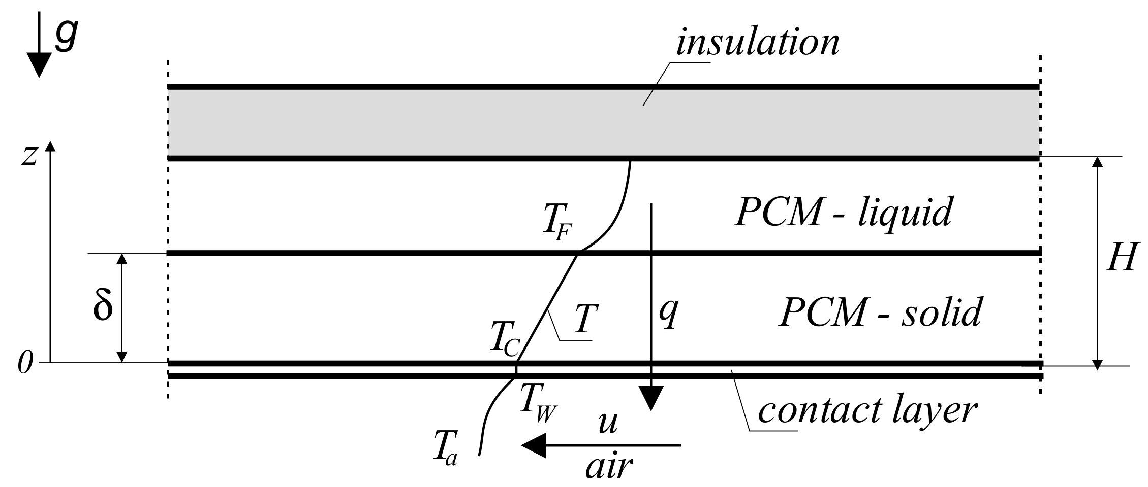
2.1. Theoretical Model of Solidification of PCM Plate
- -
- For the solidified layer in the space :
- -
- For the stand still liquid in the space
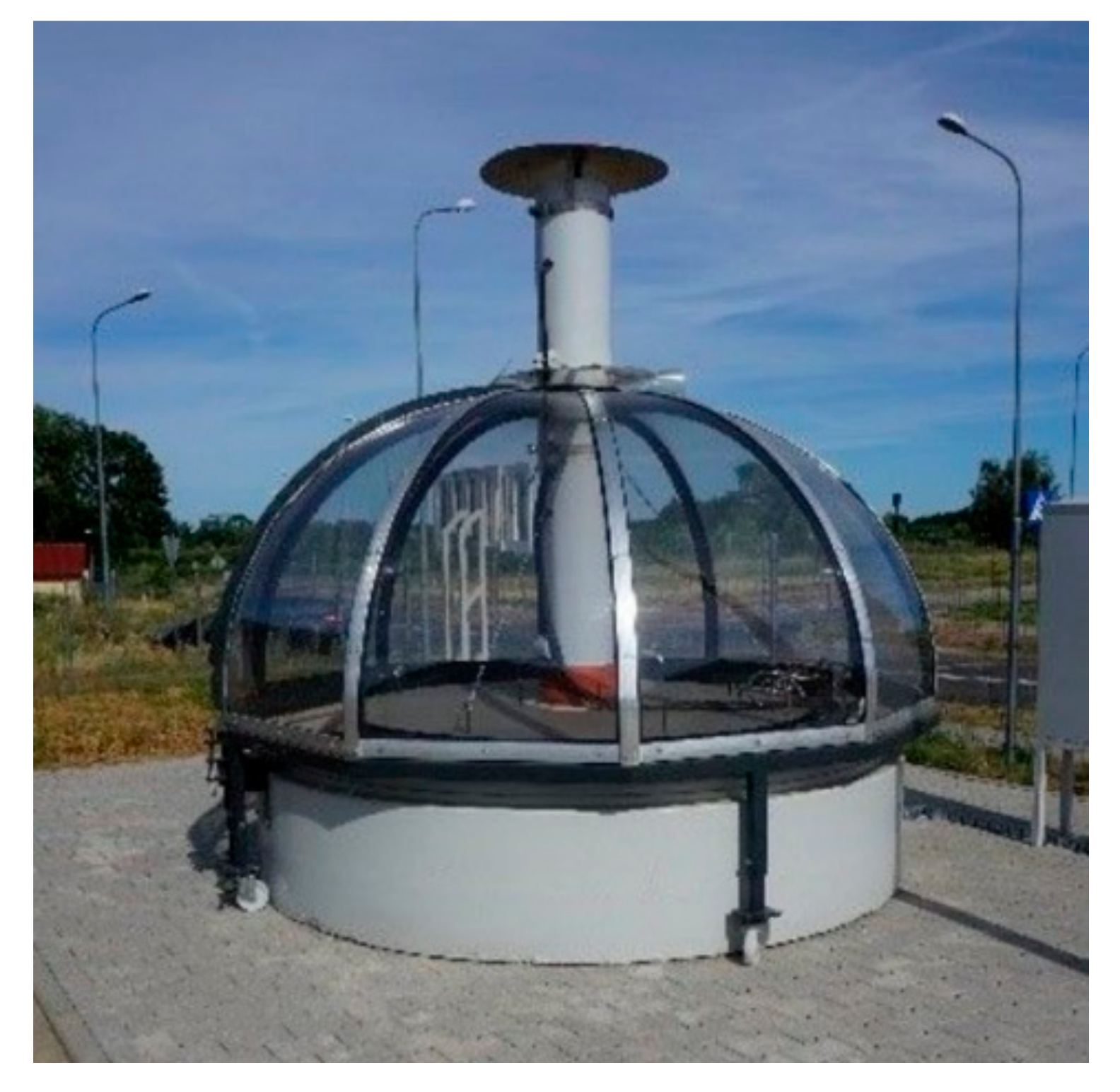
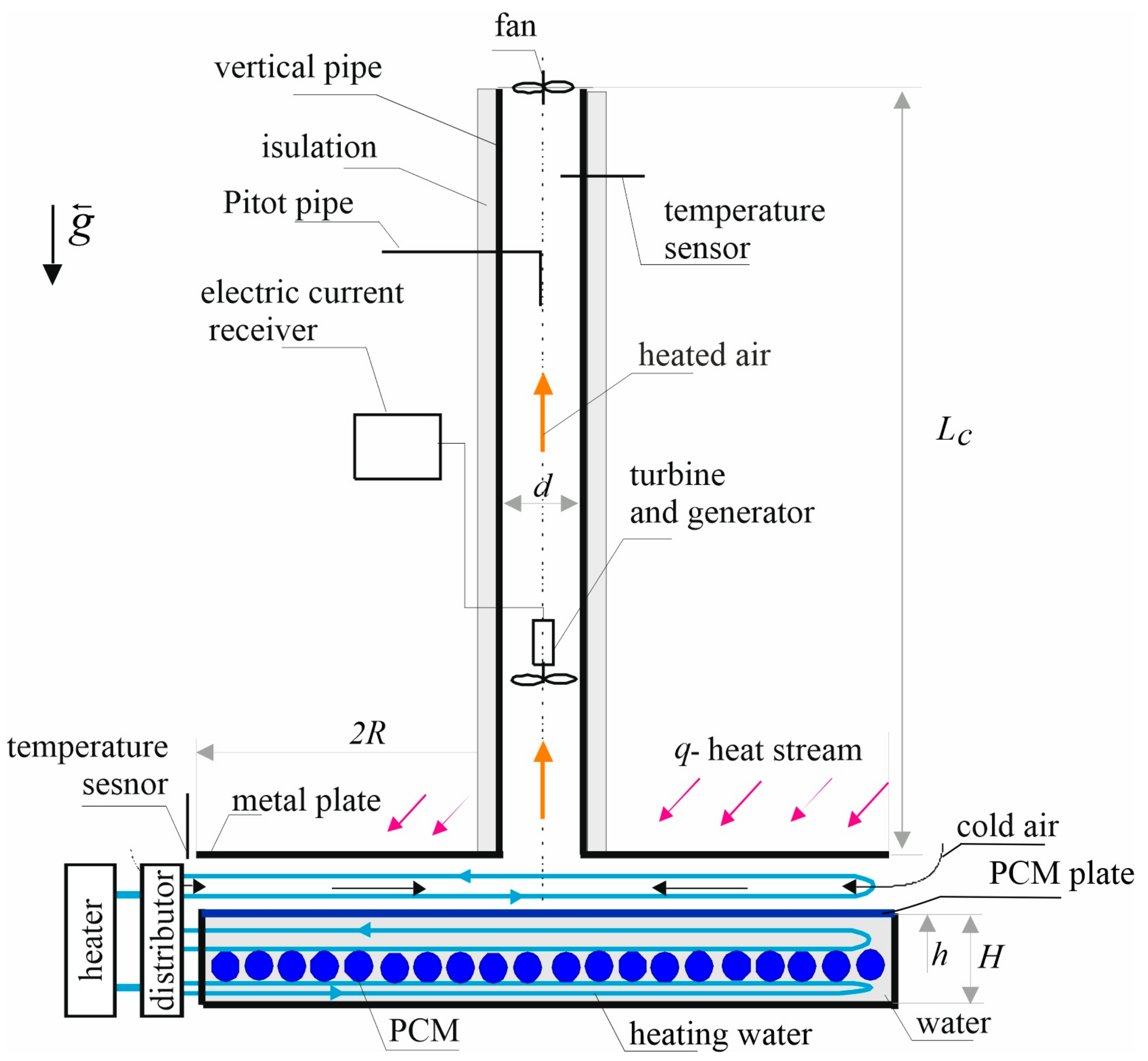
2.2. The Mini Solar Chimney
- -
- The first one is placed on the bottom plate of the solar collector, within the space of the flowing air. In this case, the air in the gap of the solar collector is heated by the heat of the solar radiation.
- -
- The second one is placed in the tank space under the solar collector, where the PCM material is placed, which works in two cycles:
- -
- Melting of the PCM material by the warm air flowing in the collector gap (charging of the storage tank);
- -
- Solidification of the PCM material by the cold air flowing in the collector gap (discharging the heat storage tank).
- -
- The third is at the bottom of the tank, under the solar collector. In this case, the air in the collector gap is heated by the heat from the heat exchanger.
- -
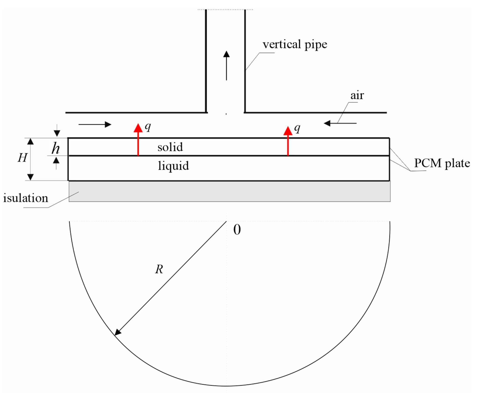
- The solar chimney co-operates with a round flat plate of phase change material (PCM), which solidifies when air flows through the collector gap. The solidification process of the liquid PCM material is shown in Figure 5.
- -
- The air flowing in the collector gap has a velocity u and an average temperature lower than the solidification temperature of the PCM material. As a result of the process of absorbing heat from the liquid, it is in the form of a cylindrical plate, with a radius and a thickness where the solidification process of the PCM material takes place.
3. Results and Discussion
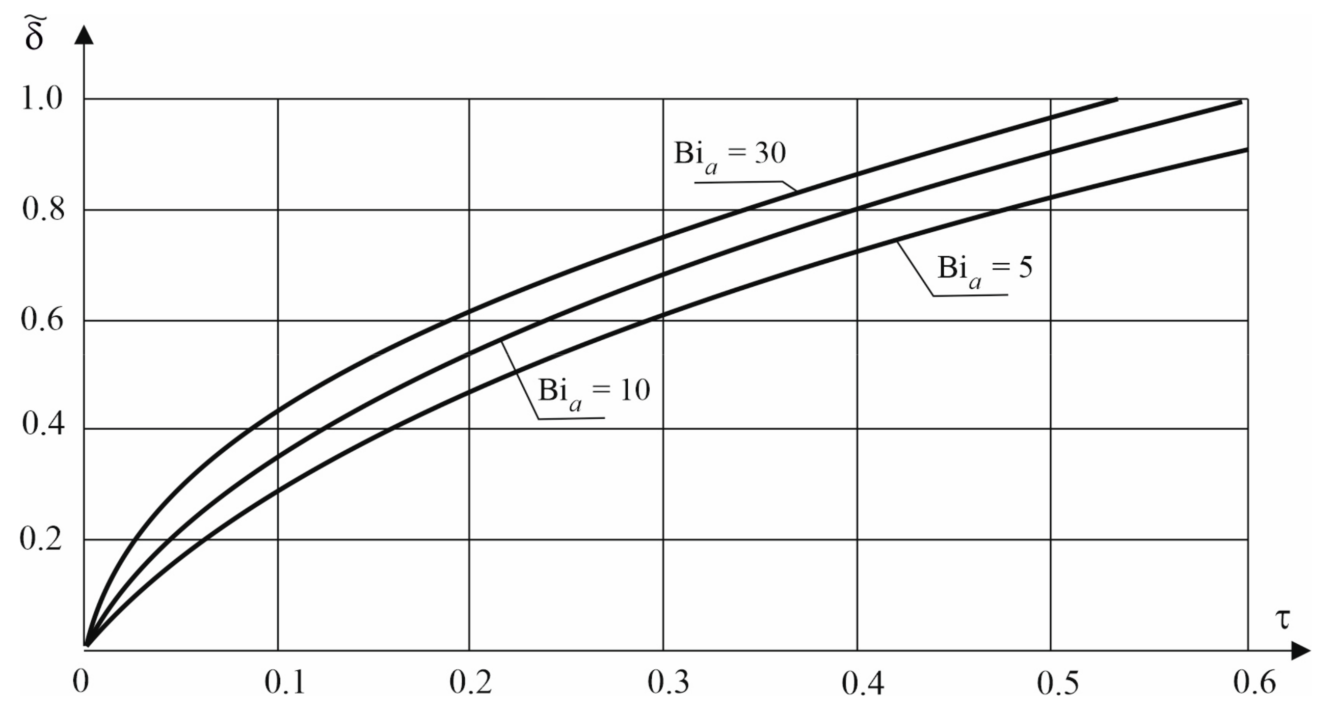
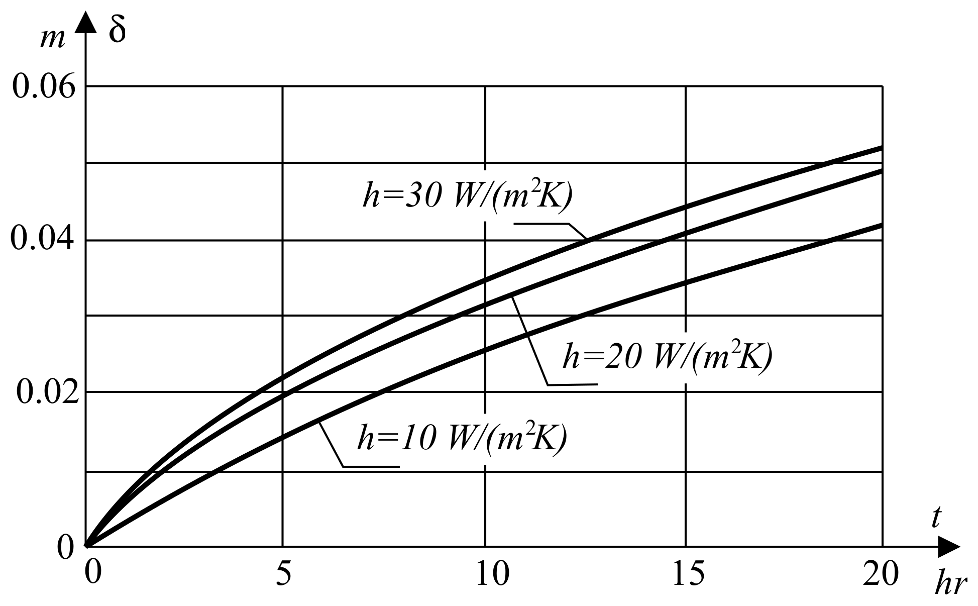
3.1. Solidification of PCM Plate
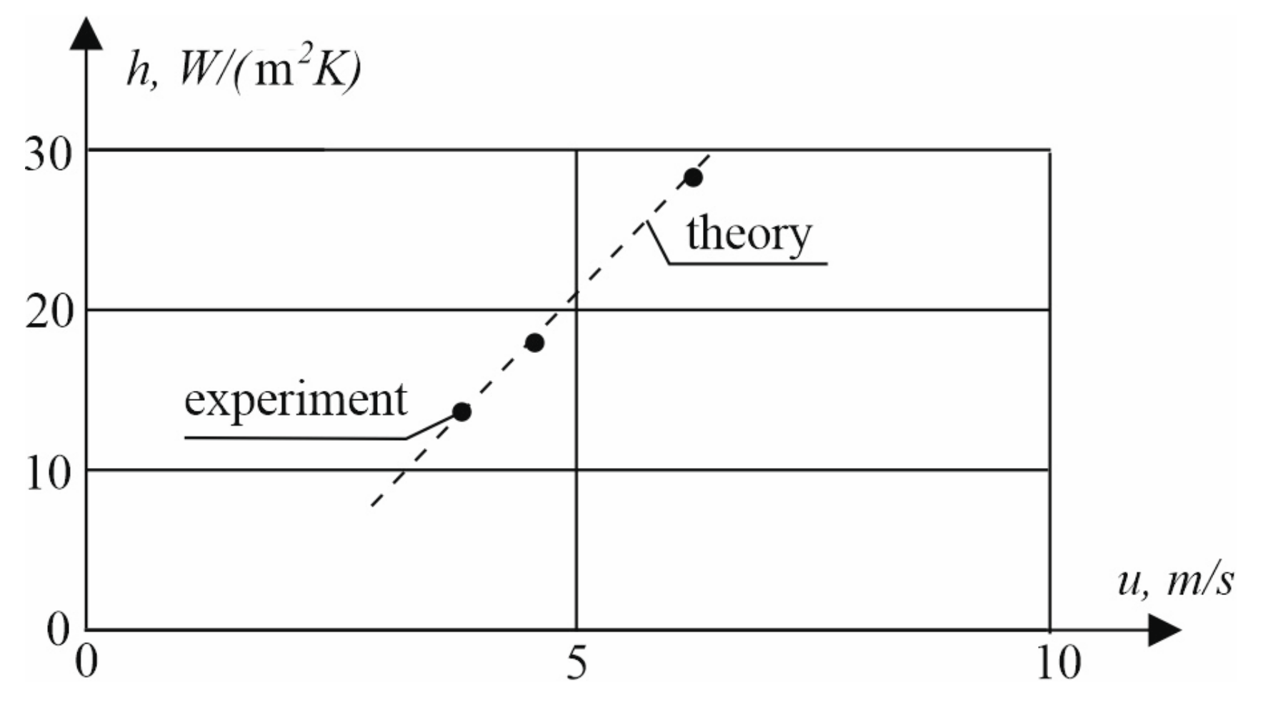
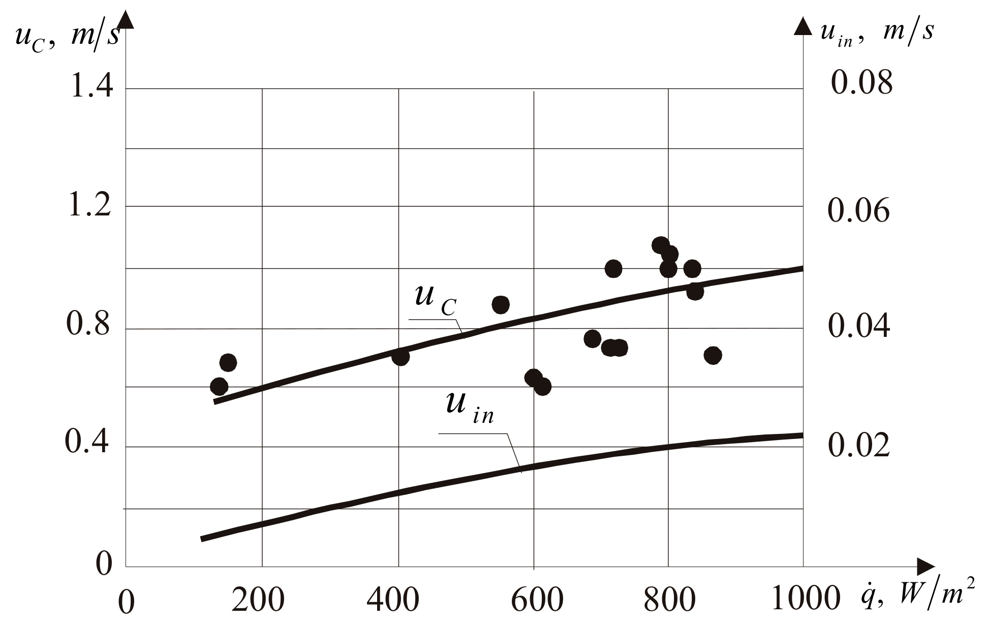
3.2. Determination of the Heat Transfer Coefficient
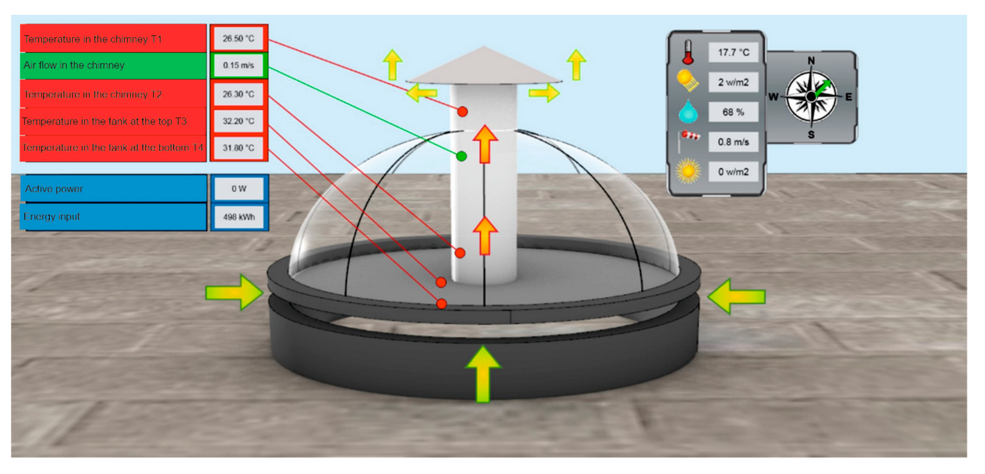
3.3. Examples of Mini-Chimney Operation Processes
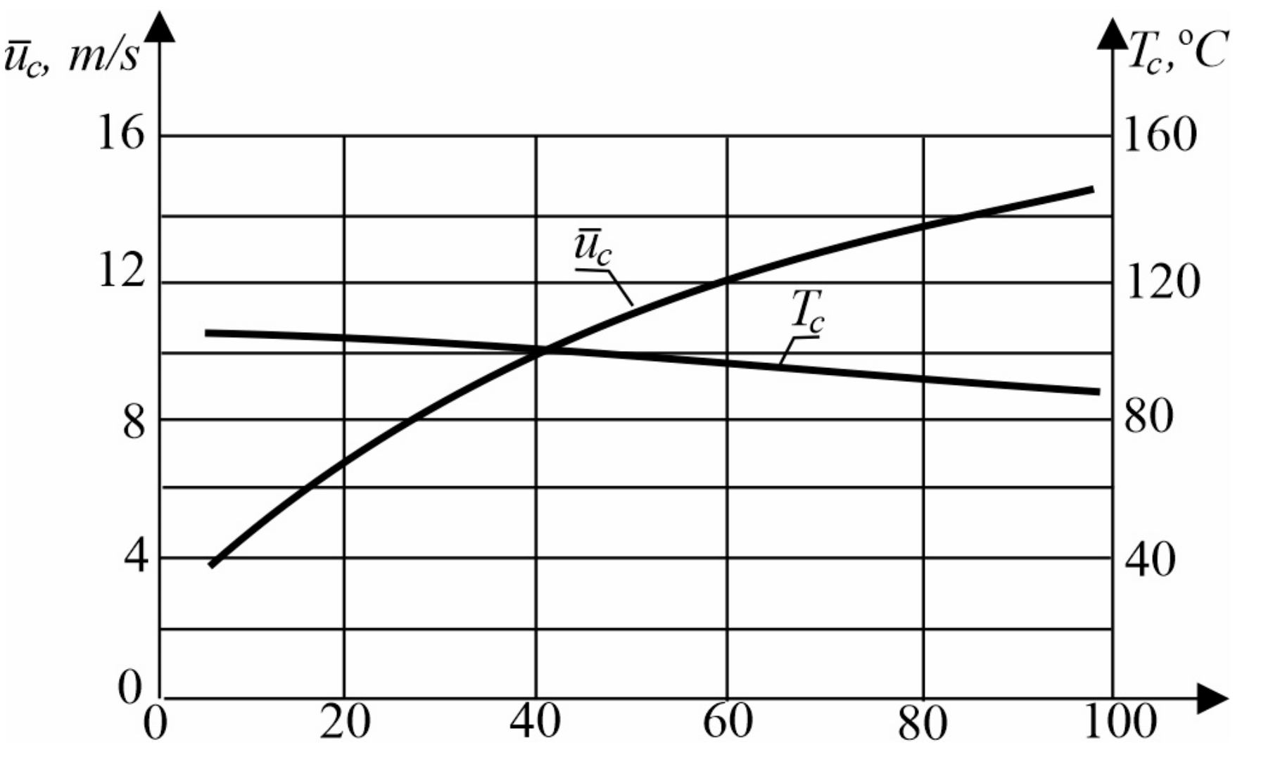
3.3.1. Heating the Air in the Collector Gap with the Heat of the Solidification Stream
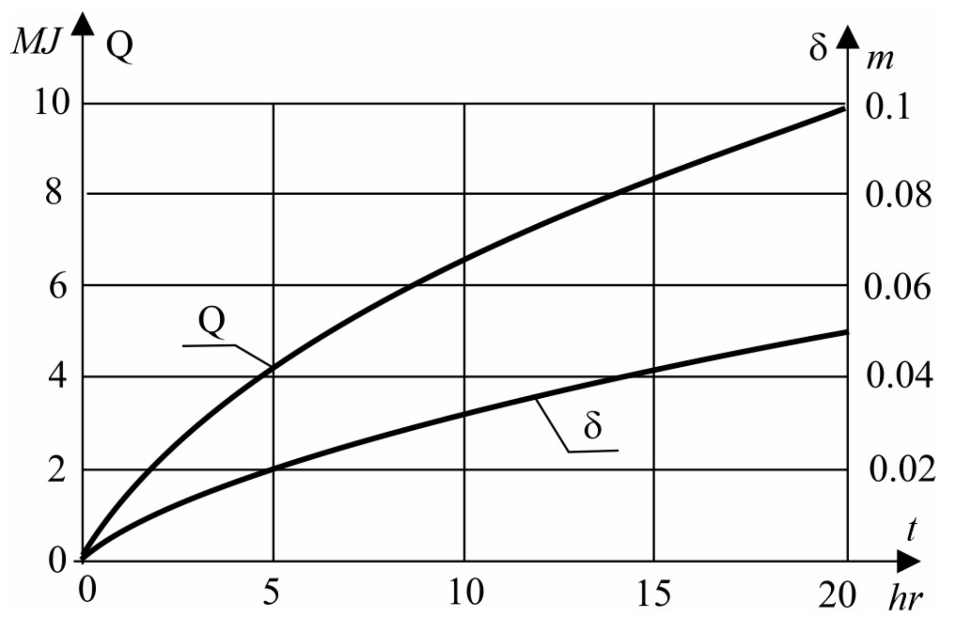
3.3.2. The Heat Flow from the Flat Lower Circular Plate in the Collector Gap
4. Conclusions
Author Contributions
Funding
Data Availability Statement
Conflicts of Interest
Nomenclature
| thermal diffusivity of the solidified layer, | |
| thermal diffusivity of the liquid, | |
| specific heat of the solidified layer, | |
| specific heat of the liquid, | |
| gravity of acceleration, | |
| heat transfer coefficient at the plate, | |
| heat transfer coefficient at the solidification front, | |
| heat transfer coefficient at the contact layer, | |
| heat conductivity of liquid, | |
| heat conductivity of the solidified layer, | |
| heat conductivity of cooling liquid, | |
| plate PCM material height, | |
| latent heat of liquid, | |
| heat conductivity, | |
| chimney length, | |
| heat flux, | |
| heat transfer rate, | |
| time, | |
| temperature, | |
| velocity, | |
| coordinate, | |
| Greek symbols | |
| thickness of the solid layer, | |
| density, | |
| overheat temperature of the liquid | |
| time | |
References
- Asnaghi, A.; Ladjevardi, S.M. Solar chimney power plant performance in Iran. Renew. Sustain. Energy Rev. 2012, 16, 3383–3390. [Google Scholar] [CrossRef]
- Haaf, W.; Friedrich, K.; Mayr, G.; Schlaich, J. Solar Chimneys—Part I: Principle and Construction of the Pilot Plant in Manzanares; Taylor & Francis: Abingdon, UK, 1983; pp. 3–20. [Google Scholar]
- Bernardes, M.A.d.S.; Voß, A.; Weinrebe, G. Thermal and technical analyses of solar chimneys. Sol. Energy 2003, 75, 511–524. [Google Scholar] [CrossRef]
- Cabanyes, I. Proyecto de Motor Solar. Energ. Eléctrica—Rev. Gen. Electr. Sus Apl. 1903, 8, 61–65. [Google Scholar]
- Lipnicki, Z. Dynamics of Liquid Solidification, Thermal Resistance of Contact Layer; Mathematical Engineeringm; Springer International Publishing: Cham, Switzerland, 2017. [Google Scholar]
- Lipnicki, Z.; Gortych, M.; Staszczuk, A.; Kuczyński, T. The theoretical analysis of mass and energy flow through solar collector—Chimney system. Civ. Environ. Eng. Rep. 2017, 24, 117–131. [Google Scholar] [CrossRef]
- Lipnicki, Z.; Gortych, M.; Staszczuk, A.; Kuczyński, T.; Grabas, P. Analytical and Experimental Investigation of the Solar Chimney System. Energies 2019, 12, 2060. [Google Scholar] [CrossRef]
- Schlaich, J. The Solar Chimney. Electricity from the Sun; Edition Axel Menges: Stuttgart, Germany, 1995. [Google Scholar]
- Mehling, H.; Cobeza, L. Heat and Cold Storage with PCM; Springer: Berlin/Heidelberg, Germany, 2008. [Google Scholar]
- Lipnicki, Z.; Rubaszewski, A. Współpraca akumulatora ciepła z układem chłodzenia silnika spalinowego. Arch. Motoryz. 2000, 3, 177–186. [Google Scholar]
- Ahmed, O.K.; Algburi, S.; Ali, Z.H.; Ahmed, A.K.; Shubat, H.N. Hybrid solar chimneys: A comprehensive review. Energy Rep. 2022, 8, 438–460. [Google Scholar] [CrossRef]
- Yazdi, M.H.; Solomin, E.; Fudholi, A.; Sopian, K.; Chong, P.L. Numerical analysis of the performance of a hybrid solar chimney system with an integrated external thermal source. Therm. Sci. Eng. Prog. 2021, 26, 101127. [Google Scholar] [CrossRef]
- Behar, O.; Sbarbaro, D.; Morán, L. A Practical Methodology for the Design and Cost Estimation of Solar Tower Power Plants. Sustainability 2020, 12, 8708. [Google Scholar] [CrossRef]
- Albarbar, A.; Arar, A. Performance Assessment and Improvement of Central Receivers Used for Solar Thermal Plants. Energies 2019, 12, 3079. [Google Scholar] [CrossRef]
- Khosravi, A.; Malekan, M.; Pabon, J.J.G.; Zhao, X.; Assad, M.E.H. Design parameter modelling of solar power tower system using adaptive neuro-fuzzy inference system optimized with a combination of genetic algorithm and teaching learning-based optimization algorithm. J. Clean. Prod. 2020, 244, 118904. [Google Scholar] [CrossRef]
- Ahmed, O.K.; Hussein, A.S. New design of solar chimney (case study). Case Stud. Therm. Eng. 2018, 11, 105–112. [Google Scholar] [CrossRef]
- Arzpeyma, M.; Mekhilef, S.; Kazi, S.N.; Horan, B.; Seyedmahmoudian, M.; Akram, N.; Stojcevski, A. Solar chimney power plant and its correlation with ambient wind effect. J. Therm. Anal. Calorim. 2019, 141, 649–668. [Google Scholar] [CrossRef]
- Arzpeyma, M.; Mekhilef, S.; Kazi, S.N.; Horan, B.; Seyedmahmoudian, M.; Akram, N.; Stojcevski, A.; Alnaimat, F.; Mathew, B. Numerical simulation of the effect of chimney configuration on the performance of a solar chimney power plant. J. Therm. Anal. Calorim. 2021, 147, 2549–2563. [Google Scholar] [CrossRef]
- Guo, P.; Li, T.; Xu, B.; Xu, X.; Li, J. Questions and current understanding about solar chimney power plant: A review. Energy Convers. Manag. 2018, 182, 21–33. [Google Scholar] [CrossRef]
- Guo, P.; Wang, Y.; Li, J.; Wang, Y. Thermodynamic analysis of a solar chimney power plant system with soil heat storage. Appl. Therm. Eng. 2016, 100, 1076–1084. [Google Scholar] [CrossRef]
- Habibollahzade, A.; Houshfar, E.; Ashjaee, M.; Ekradi, K. Continuous power generation through a novel solar/geothermal chimney system: Technical/cost analyses and multi-objective particle swarm optimization. J. Clean. Prod. 2021, 283, 124666. [Google Scholar] [CrossRef]
- Tajemnicze Aqda i Nocleg w Świątyni Zoroastrian. Available online: https://kolemsietoczy.pl/tajemnicza-aqda-nocleg-w-swiatyni-zoroastrian/ (accessed on 8 July 2022).
- Modele Krzepnięcia Materiałów PCM w Różnych Układach Geometrycznych. Available online: https://projekt-energie.eu/pl/platforma-edukacyjna/article-modele-krzepniecia-materialow-pcm-w-roznych-ukladach-geometrycznych.html (accessed on 11 June 2023).
- RUBITHERM. RT64HC. Available online: https://www.rubitherm.eu/media/products/datasheets/Techdata_-RT64HC_EN_09102020.PDF (accessed on 12 July 2022).
- Płuciennik-Koropczuk, E.; Myszograj, S.; Mąkowski, M. Reducing CO2 Emissions from Wastewater Treatment Plants by Utilising Renewable Energy Sources? Case Study. Energies 2022, 15, 8446. [Google Scholar] [CrossRef]
- Myszograj, S.; Bocheński, D.; Mąkowski, M.; Płuciennik-Koropczuk, E. Biogas, Solar and Geothermal Energy—The Way to a Net-Zero Energy Wastewater Treatment Plant—A Case Study. Energies 2021, 14, 6898. [Google Scholar] [CrossRef]
- Kumar, D.; Biswas, N.; Manna, N.K.; Cemal, A. Impact of chimney divergence and sloped absorber on energy efficacy of a solar chimney power plant (SCPP). Ain Shams Eng. J. 2024, 15, 102390. [Google Scholar] [CrossRef]
- Pradhan, S.; Chakraborty, R.; Mandal, D.K.; Barman, A.; Bose, P. Design and performance analysis of solar chimney power plant (SCPP): A review. Sustain. Energy Technol. Assess. 2021, 47, 101411. [Google Scholar] [CrossRef]
- Das, P.; Chandramohan, V.P. A review on solar updraft tower plant technology: Thermodynamic analysis, worldwide status, recent advances, major challenges and opportunities. Sustain. Energy Technol. Assess. 2022, 52, 102091. [Google Scholar] [CrossRef]
- Saleh, M.J.; Atallah, F.S.; Algburi, S.; Ahmed, O.K. Enhancement methods of the performance of a solar chimney power plant: Review. Results Eng. 2023, 19, 101375. [Google Scholar] [CrossRef]
- Taler, J.; Duda, P. Rozwiązania Prostych i Odwrotnych Zagadnień Przewodzenia Ciepła; Wydawnictwo Naukowo-Techniczne: Warszawa, Poland, 2003. [Google Scholar]


| Date/Time | Air Flow Velocity in the Chimney [m/s] | External Wind Speed [m/s] | Insolation [W/m2] | Air Temperature [°C] | Air Flow Velocity in the Chimney [m/s] |
|---|---|---|---|---|---|
| 8 February 2020 | 0.7 | 25 | 279.2 | 4.1 | 0.7 |
| 11 February 2020 | 1.1 | 7.2 | 164.9 | 5.8 | 1.1 |
| 2 September 2022 | 2.1 | 1.0 | 846.6 | 21.2 | 2.1 |
| 3 September 2022 | 0.6 | 0 | 2 | 14.1 | 0.6 |
Disclaimer/Publisher’s Note: The statements, opinions and data contained in all publications are solely those of the individual author(s) and contributor(s) and not of MDPI and/or the editor(s). MDPI and/or the editor(s) disclaim responsibility for any injury to people or property resulting from any ideas, methods, instructions or products referred to in the content. |
© 2024 by the authors. Licensee MDPI, Basel, Switzerland. This article is an open access article distributed under the terms and conditions of the Creative Commons Attribution (CC BY) license (https://creativecommons.org/licenses/by/4.0/).
Share and Cite
Gortych, M.; Lipnicki, Z.; Małolepszy, T.; Grabas, P. Solar Chimney Operation Variant. Energies 2024, 17, 5004. https://doi.org/10.3390/en17195004
Gortych M, Lipnicki Z, Małolepszy T, Grabas P. Solar Chimney Operation Variant. Energies. 2024; 17(19):5004. https://doi.org/10.3390/en17195004
Chicago/Turabian StyleGortych, Marta, Zygmunt Lipnicki, Tomasz Małolepszy, and Piotr Grabas. 2024. "Solar Chimney Operation Variant" Energies 17, no. 19: 5004. https://doi.org/10.3390/en17195004