Abstract
The oxygen blast furnace (OBF) process with top gas recycling is recognized as a promising ironmaking process, due to its high productivity and low CO2 emissions. The solid flow plays a crucial role in this process. Therefore, the solid flow in OBF was investigated using a cold experimental OBF model in this paper. The results indicate that the plug flow is the primary solid flow pattern in the upper and middle zones of the OBF. A slight convergence flow and a smaller deadman zone were observed at the bosh. The influence of recycled gas on solid flow was found to be quite limited. Additionally, the raceway size affects the burden structure and deadman zone, but the production rate had little impact. Both the raceway size and production rate have different effects on the repose angle of the deadman zone, and it varies by 14–18°. The findings of this study may have important implications for understanding the structure of solid flow in OBF. The results can be used to optimize the process parameters and equipment design to improve the efficiency of iron production while reducing environmental impact.
1. Introduction
A blast furnace (BF) is a complex metallurgical reactor that can be used to produce liquid iron. In the iron and steel manufacturing process, BFs are widely acknowledged as being the most energy-consuming reactors, taking up about 75% of the energy consumption of the whole process [1,2]. Therefore, oxygen blast furnaces (OBFs) are a good tool to enhance the efficiency and reduce the energy consumption of the BF sector, which is of great significance not only from the perspective of environmental protection, but also from the economic perspective [3,4,5]. Oxygen blast furnace ironmaking is a new ironmaking technology. It can achieve pure oxygen blast, top gas circulation and large amount of coal injection, and has the following advantages: (1) high productivity; (2) a low coke ratio and a low fuel ratio [6]; and (3) an improved reaction stability of the blast furnace [7,8]. In the early development stage of OBFs, a semi-industrial experiment was carried out [3]. Due to the small amount of gas in the furnace, the burden was not high enough and the temperature of the furnace cylinder was too high, and thus the experiment ended in failure. There are two main reasons for the test failure: (1) Pure oxygen is pumped through the tuyere, meaning that the amount of gas is very small, which causes the charge to not receive enough heat in the furnace body area; this phenomenon is called “insufficient heat in the upper blast furnace”. (2) Due to the increase in the theoretical combustion temperature, the reduction in the amount of gas and the reduction in the direct reduction degree, the temperature of the furnace cylinder area will be very high, which is called “lower furnace overheating”. In order to overcome the above problems, Yotaro, O et al. [9] and Qin et al. [10] proposed injecting preheated gas into the upper or lower parts of the furnace body. Among these proposed solutions, the main features of the FOBF (full oxygen blast furnace) process proposed by Qin et al. [10] are as follows: (1) two rows of tuyere are set in the furnace cylinder and under the furnace body; and (2) the furnace cylinder tuyere is pumped with room-temperature oxygen and a large amount of pulverized coal, and the furnace top gas is used as coal carrier gas. At the same time, some top gas is fed into the furnace as a means to control the theoretical combustion temperature. Therefore, it is necessary and important to understand the solid flow of coke and ore particles in OBFs.
There are not many experiments on the solid flow, especially for oxygen blast furnaces [11]. Takahashi et al. [12] and Kawai et al. [13] established a two-dimensional blast furnace model. The wall in this model is made of transparent material, meaning that the state of the descending movement of the charge in the model can be directly observed in real time, and the experimental data can be obtained via photographs after the end of the experiment. In the process of lowering the charge, a large dead zone is formed. Guili et al. [14] studied the effect of particle diameter on the descending movement of feed flow by using a two-dimensional slot model, and found that when the particle diameter decreased, the height of the dead column increased significantly, resulting in the increase in the height of the quasi-stagnation zone and the appearance of a converging flow in advance. A weak “W” shape could be seen in the burden layer structure below the furnace belly observed on the flat wall. Wright et al. [15] built a 3D blast furnace model, and the physical model was scaled down to 1/32 based on a real BF using the Fr number. They found that the solid flow in a conventional BF could be divided into four parts: the stagnant zone, the plug flow, the funnel flow and the quasi-stagnant zone.
The recycled gas in the furnace body can effectively reduce the carbon emission intensity of the BF process [2,16], and in an earlier research work, the relationship between the coke replacement rate and top gas recycling in OBFs was discussed [17]. Primary gas is provided upward in the roundabout area at the lower part of the blast furnace, and the interaction between the gas and the solid can affect the downward movement of the charge. Through cold experiments, Zhang et al. [18] found that with the increase in gas flow in the cyclotron zone, the deadman column gradually increased, which greatly affected the movement of the piston flow. Zhou et al. [19,20] found through the numerical model that with the increase in gas flow, the movement rate of the charge slows down, and the stagnation zone, quasi-stagnation zone and convergent flow zone in the structure of the charge all move upward, and the area of the region expands.
The stable operation of an OBF relies heavily on the recycled gas and raceway. To investigate their effects, a 3D half-circle OBF (180°) model made from transparent acrylic material was developed in this study. A burden cutting method [21] was employed to observe the internal structure of the solid flow within the OBF. These findings have significant implications for understanding the solid flow structure in OBFs.
2. Materials and Methods
2.1. Experiment Setup
The experimental model of a commercial blast furnace used in this paper was scaled down by 1/15, as shown in Figure 1. Figure 1a shows the schematic of the cold experimental BF model. The experimental system consisted of an oil-free silent air compressor, a flow-regulating valve, a pressure-regulating valve, an oil–water separator, a glass rotameter, a blast furnace half furnace model, a motor, and a spiral discharge device. During the experiment, particles were added to the model from the upper part of the model, and the model was discharged in the raceway. The discharge speed was controlled by the spiral discharge device to simulate the disappearance of particles. A blast was provided by the air compressor, and the air entered the model through the flow-regulating valve, the pressure-regulating valve, the oil–water separator, the glass rotameter and the tuyere to simulate the updraft in the actual blast furnace. The BF model maintained good sealing properties with the interface of the tuyere, spiral discharge device and recovery bin, which ensured the accuracy of the results. As the OBF was designed with recycled gas in the body, the recycled gas design is shown in Figure 1b. The parameters of the experimental model are shown in Table 1.
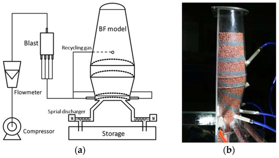
Figure 1.
The 3D half-circle OBF model. (a) Schematic of the 3D experimental OBF model; (b) the image of OBF model with recycled gas.

Table 1.
Parameters of the experimental model.
The experimental particles used in this paper were cylindrical polyethylene particles. Two kinds of experimental particles were used—dark red polyethylene particles and yellow polyethylene particles. The particles of the two different colors had exactly the same properties. The granulometry of the particles was 4 mm (diameter). The diameter of the particles in actual blast furnaces is roughly 5 mm~80 mm, and so the particle diameter ranged from 2 mm to 35 mm. The diameter of the polyethylene particles selected in the experiment was 3~5 mm, meeting the requirements. The packing angle of polyethylene particles of this shape is 40°. The accumulation angle of the actual coke is generally between 35° and 45°, so the choice of cylindrical polyethylene particles is more suitable. Among them, in order to distinguish between the two experiments, different color particles were used—dark red particles for the recycled gas experiment and yellow particles the raceway experiment. In order to characterize the burden layer, it was necessary to add tracer particles at regular intervals to characterize the traces lines and timelines. The tracer particles in the experiment were black polyethylene particles with a diameter of 2.5 mm, and other parameters were consistent with those of the dark red particles and yellow particles.
After conducting preliminary experiments, the descent velocity of the particles was determined. In general, considering the Froude similarity of the particles, the velocities of burden can be calculated using the Froude number [15,22]:
The density of the solid and gas phases is represented by and , respectively. denotes the equivalent diameter of the particles, while represents their descending velocity at the furnace throat. The modified Frs and Frg factors account for the inertial forces acting on the solid and gas phases, respectively. Based on operational data from a blast furnace (BF), the particle descending speed in our model was maintained at 3.45 × 10⁻⁴ m/s (* under basic conditions).
2.2. Particle Properties
Two distinct cylindrical polyethylene particles were utilized as burden and tracer particles to visualize the motion of the burden and the distribution of descending velocity. Specifically, in the 3D half-circle OBF model, dark red and yellow particles served as burden particles, while small dark blue particles acted as tracer particles. The trace lines and timelines formed by these tracer particles facilitated the analysis of the solid flow structure. All cylindrical polyethylene particles possessed a repose angle of 40°, consistent with the typical range (35°–45°) observed for coke. Furthermore, these particles had a diameter ranging from 3 to 5 mm, a real density of 910 kg/m3, a burden porosity of 0.35, and an elastic modulus of 1.07 GPa. The static friction coefficient between polyethylene particles and the outer wall made from acrylic was determined to be 0.156, whereas between polyethylene particle surfaces, it was found to be approximately 0.21.
2.3. Experimental Procedure
In the experiment, initially, the OBF model was filled with polyethylene particles. Subsequently, the charging and discharging system was activated. The first layer of the tracer particles were evenly charged from the top. Then, alternatingly, burden particles (red or yellow) and tracer particles (black) were charged into the OBF model. Tracer particles were periodically charged into the OBF model at specific intervals to form multiple thin layers serving as timelines. The charging and discharging system was deactivated once the first layer of tracer particles reached the outlets. At this point, a solidified burden body had formed, which could be utilized to investigate the solid flow structure through two parameters: recycled gas and raceway factors.
It is extremely challenging to study the burden movement in a blast furnace, due to its enclosed nature and complex operational conditions. Therefore, the primary requirement for this experiment is ease of observation and photography. There are three main driving forces behind solid particle movement in a blast furnace: coke combustion in the tuyere, coke combustion in the raceway, and ore soft melting digestion in the soft zone. Compared to coke combustion in the tuyere, coke consumption in the hearth area is negligible and thus ignored in the experimental model. Similarly, iron ore melting in the soft melt zone has no significant impact on solid descent as it mainly occurs above the deadman zone. The melting of iron ore only serves to enhance the motion of the solid layer above, without exerting any influence on the flow behavior below that particular zone. Hence, coke combustion in the raceway is primarily responsible for burden descent, while disregarding any influence from coke combustion or ore melting elsewhere. Consequently, discharging solid flow at the raceway aligns better with actual conditions. The half-furnace model can observe the timelines of the burden. Both results (outer wall and inner surface) are important for the study of the charge flow distribution in the furnace [21]. The experimental steps in this paper are as follows:
- (1)
- Before the start of the experiment, adjust the motor speed and ensure that each motor has the same speed, so that each discharge speed is the same;
- (2)
- Fill the OBF model with red/yellow polyethylene particles, turn on the motor (spiral discharge device), and the solid flow decreases with the continuous discharge of particles;
- (3)
- In order to maintain the dynamic balance of the burden layer, the upper part of the OBF model is constantly filled with polyethylene particles to maintain the stability of the burden layer’s height;
- (4)
- In order to facilitate the observation of the timelines, 10 mm thick black tracer particles are loaded into the upper part of OBF model, and then polyethylene particles of a certain thickness are loaded. Polyethylene particles and black tracer particles are added at intervals, and the particles are loaded at the same time interval;
- (5)
- Stop the discharge until the first layer of tracer particles are discharged from the discharge port;
- (6)
- Cut the experimental products, observe the internal solid flow timelines, and take photos.
3. Results and Discussion
3.1. Effects of Recycled Gas
In an oxygen blast furnace, the burden layer needs to be preheated by feeding recycled gas into the upper furnace. At present, it is generally believed that the height of recycled gas should be at the lower part of the furnace body [23,24]. A new gas injection method was proposed in this study with an angle of 45 degrees downward, in order to make the air flow to the middle of the blast furnace to solve the “upper cold” problem. The blast flow rate of the recycled gas (with only one air outlet) and the lower single air outlet was set at 2 m3/h. The prototype blast furnace had eight tuyeres. In the traditional blast furnace, the lower blast has a great influence on the solid flow movement and gas distribution. In principle, the total air volume of the up-and-down blast remains unchanged.
Figure 2 shows a burden structure with upper and lower blast conditions. There is no significant difference in the particle descending motion between the lower blast and the non-blast conditions compared with [21]. The comparison of the two results is shown in Figure 2a,d. Under the standard working conditions, the blast flow rate is 2 m3/h in every tuyere. Oxygen blast furnaces need to be preheated by feeding recycled gas into the upper burden layer of the furnace because of its cooling and heating [25]. In order to study the influence of recycled gas, according to the previous calculation, the blast flow rate of recycled gas (with only one air outlet) needs to be calculated. The other parameters and the experimental process are unchanged. The timeline distribution is shown in Figure 2a. Comparing the timeline distribution of the two graphs, it is found that the overall speed of the burden layer’s descent increases without a blast, but the descent law is basically the same. It can be concluded that the change in the lower tuyere blast has little effect on the burden’s descent behavior.
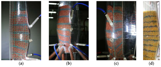
Figure 2.
The solid flow under the conditions of upper and lower tuyeres. (a) The timelines after the implementation of the cutting method; (b) the timelines of the circumferential wall; (c) the comparison between the circumferential wall and the internal symmetrical surface under the condition of upper and lower blast; (d) the result of the inner wall in [21].
Therefore, in the subsequent experiments, the lower tuyere and upper recycled gas were not utilized as essential conditions for the experiment. From the experimental results of a double blast, the overall movement of the burden exhibited plug flow, with a convergence phenomenon occurring in the lower region. Comparing these results with Figure 2, there is minimal disparity between them. The solid–solid flow is primarily characterized by piston flow, and the impact of blast conditions on the general trend of downward solid flow movement is limited; however, recycled gas near the upper tuyere has a greater influence. In order to elucidate more clearly how recycled gas affects particles’ descending motion, an experiment involving recycled gas within a single furnace body was conducted. The blast flow rate of recycled gas (with only one tuyere) was set at 7.5 m3/h, while maintaining a discharge flow rate controlled at 0.24 kg/min. The gas flow rate was tripled during this experiment. The observed effect from outside is depicted in Figure 3a, where it becomes evident that recycled gas has a noticeable impact on the exterior surroundings of the model tuyere; specifically, it causes a V-shaped deformation in the burden layer near the tuyere opening and confusion when tracer particles reach higher levels close to this area. By means of the cutting method, the solid flow by recycled gas was obtained, as shown in Figure 3(b2), and except for a slight effect near the walls, the recycled gas has little significant effect on the internal burden.
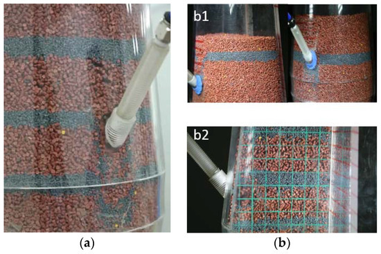
Figure 3.
The influence of recycled gas on the solid flow. (a) The influence of the upper tuyere on the timelines; (b1) the axial influence of the upper tuyere; (b2) the radial influence range of the upper tuyere.
Recycled gas has a certain influence on the burden’s descent movement, mainly affecting the axial particles near the upper tuyere, but the radial effect is very limited. The upper part of the blast furnace still shows the characteristics of plug flow, which generally does not affect the solid flow.
3.2. Effects of Raceway
Productivity is an important index of OBF, and production efficiency depends on the consumption in the raceway. This paper studies the influence of different raceways on the solid flow by adjusting the raceway sizes and particle discharge rates. The raceway is a three-dimensional cavity, according to the experimental and simulation results. In this paper, the raceway size is regarded as an ideal ellipsoid and is divided into two components, height and depth, where depth is the diameter of the transverse plane (standard circle), assuming that the height is constant. In this part of the experiment, yellow polyethylene particles were used. In this study, the main characterization parameter of raceway size was raceway depth. The burden’s descending behavior with different raceway depths, of 39 mm, 50 mm, and 61 mm (at a ratio of 7:9:11), was studied by changing the diameter of the discharge, and the particle discharging rate was 0.08 kg/min for all cases. The production rate was controlled by the particle discharging rate, at 0.04 kg/min, 0.08 kg/min and 0.16 kg/min (at a ratio of 1:2:4, case 4/case 2/case 5, respectively), and the raceway depth was 50 mm in all cases. The case 2 (*) condition was used as the contrast between the two conditions, with 50 mm and 0.08 kg/min, as shown in Table 2.
Table 2.
Parameters of the experimental model for the raceway.
Due to the influence of the raceway, another important parameter of solid flow is the top-down “traces lines”. The trace distribution in the half BF model under case 2 and a trace tool were used to obtain the trace trajectory of the tracer particles. In order to obtain the motion trajectory of the solid flow in the blast furnace, the trace distributor is designed in this paper, as shown in Figure 4a. When the tracer layer is added, the tracer particle and the yellow particle are separated by the trace distributor, meaning that the trajectory of the particle’s descending movement during the solid flow can be observed after cutting. Figure 4b shows the result of the burden trace trajectory on the flat wall, and the result is consistent with [21]. The plug flow is the main flow type in the upper part of the BF model, and the convergence phenomenon appears below the furnace belly from the observation of the flat wall. Figure 4c shows the interior surface and half flat wall after the implementation of the cutting method. The shapes of the trace trajectories on the interior surface show a huge difference in the bosh zone compared with the flat wall. The flow pattern of solid flow still mostly resembles plug flow, consistent with the expected result.
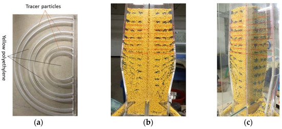
Figure 4.
Traces distribution in half BF model. (a) Distributing tool of traces lines; (b) flat wall; (c) interior surface and half flat wall after implementation of the cutting method.
Figure 5 shows the traces of the solid flow under different raceway conditions (case 1–case 3). The results show that the distributions of particle trace trajectories are similar under the three raceway sizes. The burden near the furnace wall moves downward along the track of the outer wall, and the burden near the furnace center is less affected by the furnace shape. In OBFs, oxygen injection in the hearth replaces the air blast; thus, the raceway in OBFs will become smaller as the kinetic energy reduces. However, the intense combustion reaction caused by full oxygen can also produce a larger raceway. The raceway under the conditions of an oxygen blast furnace is theoretically a small raceway zone. Figure 5(a1) shows the trace lines under a small raceway size—this condition is more similar to a real oxygen blast furnace. The outermost solid flow trace is closer to the center in a BF under the larger raceway size in Figure 5(a3), and there is no significant difference between the trace lines near the BF center.
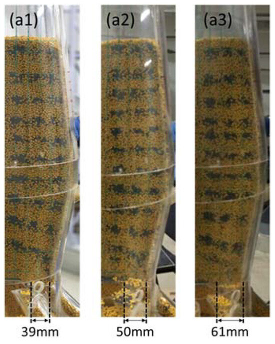
Figure 5.
Traces of solid flow under different raceway conditions—3 raceway depths: (a1) φ = 39 mm; (a2) φ = 50 mm; (a3) φ = 61 mm.
A summary of the three trace lines under different raceway sizes is presented in Figure 6a. In the case of an oxygen blast furnace, the raceway is theoretically small, and the trace of the outer solid flow is observed to be relatively close to the furnace wall. On the other hand, the inner solid flow near the BF center follows a nearly straight trajectory. Figure 6(b1) illustrates the summary of three trace lines under different particle discharge rates. Comparing these results with those obtained for raceway sizes, as shown in Figure 6(b2), it can be observed that there is no significant variation in the trace lines for case 4 and case 5. This suggests that while raceway sizes are indeed a major factor influencing the burden’s descent movement, their correlation with discharge rate is low. When an OBF operates under full or high oxygen enrichment instead of under traditional blast conditions, there is a substantial reduction in kinetic energy from blast gas injection. Therefore, it becomes crucial to control the appropriate operational conditions for producing an optimal size of raceway when operating an oxygen blast furnace.
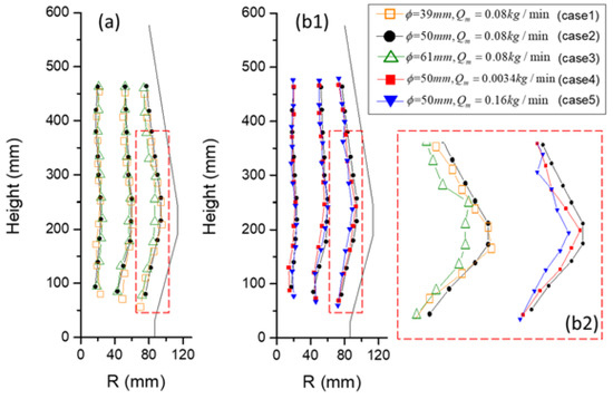
Figure 6.
(a) Traces of solid flow in different raceway sizes; (b1) traces of solid flow in different particle discharge rates; (b2) the outer trace.
The trend of the timeline is consistent across all five raceways. Figure 7 illustrates the timelines under different raceway conditions, ranging from case 1 to case 5. The variation in the deadman zone is reflected below the hearth area. As the raceway size increases, there is a gradual decrease in the deadman zone’s size. It should be noted that under different raceway sizes, there are significant variations in the stagnation zone size; however, the stagnation zone varies little at different discharge speeds as shown in Figure 6. This indicates that the overall burden structure of OBFs remains relatively unchanged at varying discharging speeds and that controlling the size of the raceway zone for OBFs is crucial since it affects the burden structure significantly.
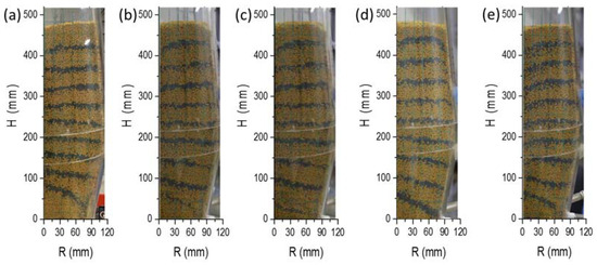
Figure 7.
Timelines under different raceway conditions: (a) case 1; (b) case 2; (c) case 3; (d) case 4; (e) case 5.
The deadman is a cylinder below the raceway, made of coke. The deadman is suspended in liquid iron by the upper particles and blast pressure. The condition of the deadman directly affects the production, and the air permeability and liquid permeability of the deadman are important for the furnace conditions. However, in OBFs, due to the reduction of coke, the shape of the deadman zone is an unknown quantity. The deadman zone under different raceway conditions is illustrated in Figure 8. Tracer particles were filled in the bosh and hearth zones, as shown in Figure 8a, and discharged until the deadman zone reaches a steady state. Figure 8b–d depict the deadman zone under case 1 to case 3, revealing that the height of the deadman zone decreases with an increase in raceway size, with a more pronounced converging phenomenon observed for smaller raceways. A slight increase in deadman zone height is observed when reducing the raceway size, although this effect is not significant. However, compared to case 2 (reference condition), it is evident that case 1 has a larger deadman zone size. The reposed angles are measured at 27.8°, 21°, and 14°, respectively, as indicated by the red line in Figure 8h. Notably, there is an obvious increase in the reposed angle of the deadman zone when decreasing the raceway size. Figure 8c,e,f present the deadman zone under case 4, case 2 (reference condition), and case 5. It can be observed that as the discharging speed increases, there is a decrease in the deadman zone area; the corresponding reposed angles are measured at approximately 23°, 21° and 15°, respectively, according to the black line in Figure 8h. Additionally, Figure 8g displays all outlines of the deadman zone under case 1 to case 5, collectively illustrating that raceway size significantly influences the shape characteristics of the deadman zone. Generally speaking, under OBF conditions, the dimensions and outline of the deadman zone may slightly exceed those found in traditional blast furnaces due to smaller raceways and higher productivity. The deadman zone’s shape is more like that seen in case 5 in OBFs.
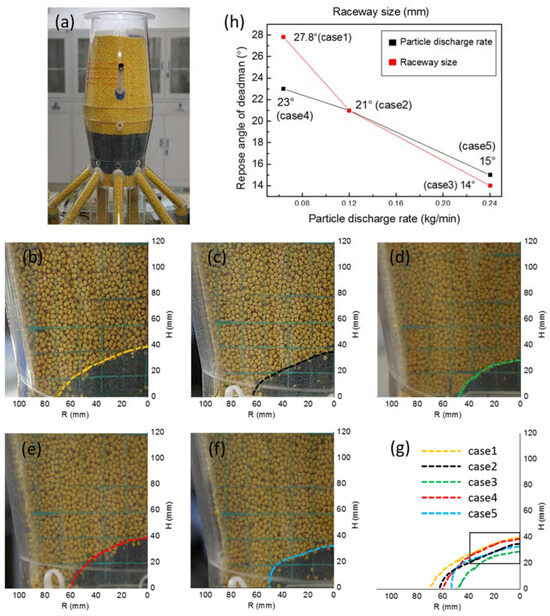
Figure 8.
The deadman zone under different raceway conditions. (a) BF model. (b) case 1; (c) case 2; (d) case 3; (e) case 4; (f) case 5; (g) outlines of deadman; (h) the repose angle of the deadman zone from case 1 to case 5.
4. Conclusions
The present study focuses on the working conditions of an oxygen blast furnace, specifically examining two aspects: the recycled gas within the furnace body and the raceway zone (including its size and production rate). The recycled gas has no obvious effect on the overall timeline distribution of the burden layer’s decline, but has a slight effect on the wall surface. Due to pure oxygen blowing, the raceway under the conditions of an oxygen blast furnace is theoretically a small raceway, while the inner track near the center of the blast furnace has no influence. After changing the discharge speed, the difference in the trace is not very obvious, indicating that the main factor influencing the trajectory of the charge drop movement is the raceway size, and the correlation with the production rate is low. The height and repose angle of the deadman zone decrease gradually with the increase in the raceway size, and the repose angle changes greatly. The cross-sectional area of deadman zone decreases with the increase in discharge velocity, and the repose angle has a small range of change. The deadman zone’s repose angle varies from 14° to 28° under different raceway sizes and discharging speeds. Therefore, compared with the traditional blast furnace, the deadman zone of the oxygen blast furnace will display a larger repose angle but a smaller cross-sectional area. Because OBFs operate under total oxygen or high oxygen enrichment instead of hot air injection, the blast energy is greatly reduced, and so it is of great significance to control the appropriate operating conditions to produce the appropriate raceway size for production in an oxygen blast furnace.
Author Contributions
Conceptualization, Y.L. and Z.J.; methodology, Y.L.; software, Y.L.; validation, Y.L., X.Z. and D.E.; investigation, Y.L. and D.E.; writing—original draft preparation, Y.L.; writing—review and editing, Y.L., Z.J., X.Z. and D.E. All authors have read and agreed to the published version of the manuscript.
Funding
This work is supported by the National Key Research and Development Program of China (2018YFB0605900), the Fundamental Research Fund for the Central Universities (FRF-TP-22-081A1), the National Natural Science Foundation of China project (52264042), the China Postdoctoral Science Foundation Funding (2021M690975) and the Jiangxi Provincial Natural Science Foundation (20212BAB214023).
Data Availability Statement
Data are contained within the article.
Conflicts of Interest
The authors declare no conflict of interest.
References
- Liu, L.; Jiang, Z.; Zhang, X.; Lu, Y.; He, J.; Wang, J.; Zhang, X. Effects of top gas recycling on in-furnace status, productivity, and energy consumption of oxygen blast furnace. Energy 2018, 163, 144–150. [Google Scholar] [CrossRef]
- Zhang, W.; Zhang, J.; Xue, Z. Exergy analyses of the oxygen blast furnace with top gas recycling process. Energy 2017, 121, 135–146. [Google Scholar] [CrossRef]
- Matsuura, M.; Mitsufuji, H.; Furukawa, T. Development of the Oxygen Blast Furnace Process. In Proceedings of the Sixth International Iron and Steel Congress, Nagoya, Japan, 21–26 October 1990. [Google Scholar]
- Song, J.; Jiang, Z.; Zhang, Y.; Han, Z.; Lu, Y.; Dong, H.; Zhang, Y. Economic Analysis of an Integrated Steel Plant Equipped with a Blast Furnace or Oxygen Blast Furnace. Sustainability 2023, 15, 11824. [Google Scholar] [CrossRef]
- Li, J.; Li, C.; Zhang, W.; Zhang, J.; Xue, Z. Material, energy and exergy flows of the oxygen blast furnace process with sintering flue gas injection. J. Clean. Prod. 2022, 371, 133294. [Google Scholar] [CrossRef]
- Zhang, H.-j.; She, X.-f.; Han, Y.-h.; Wang, J.-s.; Zeng, F.-b.; Xue, Q.-g. Softening and Melting Behavior of Ferrous Burden under Simulated Oxygen Blast Furnace Condition. J. Iron Steel Res. Int. 2015, 22, 297–303. [Google Scholar] [CrossRef]
- Li, H.; Chen, J. An Analysis of Long-Process Ironmaking in a Reduction Smelting Furnace with Hydrogen-Enriched Conditions. Metals 2023, 13, 1756. [Google Scholar] [CrossRef]
- Zhang, Z.; Tang, J.; Shi, Q.; Chu, M. Effects of Shaft Tuyere Parameters on Gas Movement Behavior and Burden Reduction in Oxygen Blast Furnace. Sustainability 2023, 15, 9159. [Google Scholar] [CrossRef]
- Yotaro, O.; Hirohisa, H.; Masahiro, M.; Hiroyuki, M.; Hiroshi, S.J.T.-t.-H. Development of Oxygen Blast Furnace Process with Preheating Gas Injection into Upper Shaft. Tetsu-to-Hagane 1989, 75, 1278–1285. [Google Scholar]
- Qin, M.S.; Qi, B.M. The full oxygen blast furnace (FOBF) process. In Proceedings of the Sixth International Iron and Steel Congress, Nagoya, Japan, 21–26 October 1990. [Google Scholar]
- Nijssen, T.M.J.; Hoeks, I.; Manjunath, V.; Kuipers, H.A.M.; van der Stel, J.; Adema, A.T.; Buist, K.A. Experiments and simulations on a cold-flow blast furnace hearth model. Chem. Eng. Sci. X 2022, 13, 100120. [Google Scholar] [CrossRef]
- Takahashi, H.; Tanno, M.; Katayama, J. Burden Descending Behaviour with Renewal of Deadman in a Two Dimensional Cold Model of Blast Furnace. ISIJ Int. 1996, 36, 1354–1359. [Google Scholar] [CrossRef]
- Kawai, H.; Takahashi, H.; Ichida, M. Segregation behavior for fine particles of sintered ores and coke supplied at the top of a two dimensional cold model of blast furnace. ISIJ Int. 2005, 45, 1112–1121. [Google Scholar] [CrossRef]
- Giuli, M.; Pinti, M.; Federico, G.; Salvatore, E. Investigation on burden descent in the blast furnace. In Proceedings of the IISC: The Sixth International Iron and Steel Congress, Nagoya, Japan, 21–26 October 1990; pp. 521–526. [Google Scholar]
- Wright, B.; Zulli, P.; Zhou, Z.; Yu, A. Gas–solid flow in an ironmaking blast furnace—I: Physical modelling. Powder Technol. 2011, 208, 86–97. [Google Scholar] [CrossRef]
- Perpiñán, J.; Bailera, M.; Peña, B.; Kannan, P.; Eveloy, V.; Romeo, L.M. Power to gas and top gas recycling integration in an oxygen blast furnace steelmaking industry. J. CO2 Util. 2023, 78, 102634. [Google Scholar] [CrossRef]
- Nishio, H.; Miyashita, T. On the top gas recycled reforming process and the injected gas Distribution. Tetsu-Hagané 1973, 59, 1506–1522. [Google Scholar] [CrossRef] [PubMed][Green Version]
- Zhang, S.J.; Yu, A.B.; Zulli, P.; Wright, B.; Tüzün, U. Modelling of the Solids Flow in a Blast Furnace. ISIJ Int. 1998, 38, 1311–1319. [Google Scholar] [CrossRef]
- Zhou, Z.; Zhu, H.; Wright, B.; Yu, A.; Zulli, P. Gas–solid flow in an ironmaking blast furnace—II: Discrete particle simulation. Powder Technol. 2011, 208, 72–85. [Google Scholar] [CrossRef]
- Zhou, Z.; Zhu, H.; Yu, A.; Zulli, P. Numerical Investigation of the Transient Multiphase Flow in an Ironmaking Blast Furnace. ISIJ Int. 2010, 50, 515–523. [Google Scholar] [CrossRef]
- Lu, Y.; Jiang, Z.; Zhang, X.; Wang, J.; Zhang, X. Vertical section observation of the solid flow in a blast furnace with a cutting method. Metals 2019, 9, 127. [Google Scholar] [CrossRef]
- Ichida, M.; Nishihara, K.; Tamura, K.; Sugata, M.; Ono, H. Influence of Ore/Coke Distribution on Descending and Melting Behavior of Burden in Blast Furnace. ISIJ Int. 1991, 31, 505–514. [Google Scholar] [CrossRef]
- Yang, W.; Zhou, Z.; Yu, A. Discrete particle simulation of solid flow in a three-dimensional blast furnace sector model. Chem. Eng. J. 2015, 278, 339–352. [Google Scholar] [CrossRef]
- Hou, Q.; Dianyu, E.; Kuang, S.; Li, Z.; Yu, A. DEM-based virtual experimental blast furnace: A quasi-steady state model. Powder Technol. 2017, 314, 557–566. [Google Scholar] [CrossRef]
- An, X.-W.; Wang, J.-S.; Lan, R.-Z.; Han, Y.-H.; Xue, Q.-G. Softening and Melting Behavior of Mixed Burden for Oxygen Blast Furnace. J. Iron Steel Res. Int. 2013, 20, 11–16. [Google Scholar] [CrossRef]


Disclaimer/Publisher’s Note: The statements, opinions and data contained in all publications are solely those of the individual author(s) and contributor(s) and not of MDPI and/or the editor(s). MDPI and/or the editor(s) disclaim responsibility for any injury to people or property resulting from any ideas, methods, instructions or products referred to in the content. |
© 2024 by the authors. Licensee MDPI, Basel, Switzerland. This article is an open access article distributed under the terms and conditions of the Creative Commons Attribution (CC BY) license (https://creativecommons.org/licenses/by/4.0/).