Article

Innovative Transformer Life Assessment Considering Moisture and Oil Circulation

1
North China Power Engineering Co., Ltd. of China Power Engineering Consulting Group, Beijing 100120, China
2
Guangxi Power Transmission and Distribution Network Lightning Protection Engineering Technology Research Center, Guangxi University, Nanning 530004, China
*
Authors to whom correspondence should be addressed.
Energies 2024, 17(2), 429; https://doi.org/10.3390/en17020429
Submission received: 29 November 2023 / Revised: 26 December 2023 / Accepted: 6 January 2024 / Published: 16 January 2024
(This article belongs to the Section F1: Electrical Power System)

Abstract

:
Power transformers are one of the most expensive and important equipment in the power system. Significant differences exist in the insulation lifespan of transformers that have been in operation for more than 20 years, and using identical maintenance or scrapping methods may result in significant economic losses. However, most existing transformer life assessment methods only consider the impact of moisture content on the life decay rate without considering the impact of oil circulation cooling modes, which leads to some evaluation errors. In this study, we established a new transformer life assessment method that considers the influence of moisture content and oil circulation cooling modes, which is more accurate than most life assessment methods. Then, the proposed life evaluation method was validated on the on-site transformers, demonstrating its accuracy and effectiveness. The novelty of this study is that it establishes a new on-site transformer life assessment method that considers the comprehensive effect of moisture content and oil circulation cooling mode, which helps to evaluate the remaining lifespan of power transformers more accurately and thus extends the transformer lifespan systematically.

1. Introduction

The safe operation of the power system is necessary to ensure a stable and reliable power supply [1]. The power transformer is a key equipment in the power transmission system [2]. However, due to the long-term operation in a high-temperature environment and other factors, such as moisture, oxygen, and AC electric field, the transformers can accelerate the aging of insulation paper. The oil-paper insulation system will gradually age, leading to a decline in its insulation performance [3,4]. As the transformer approaches its service life, its probability of failure increases [5,6]. Transformer failure may lead to serious power accidents [7,8]. In recent years, many old transformers in early-constructed power grids have approached or have already entered the aging stage, and their frequent failures due to aging have led to severe system interruptions and loss of power supply [9]. It has been observed that the main cause of transformer failure is insulation system faults, which account for about 80% of the total faults [10]. Therefore, an accurate insulation life assessment of transformers is a suitable strategy for preventing future transformer failures and increasing their service life [11].
The lifespan of oil-immersed transformers depends on the lifespan of the insulation paper [12,13], and many researchers have made important progress in the evaluation of the lifespan of transformer insulation paper. Among them, Kuhn and Ekenstam have proposed the zero-order and first-order kinetic equations [14,15], which were the basis for the second-order kinetic equations proposed by Emsley [16,17]. They have been widely used to study the degradation rate of oil-paper insulation [18]. Reference [11] proposed a method for estimating the lifetime of transformers using thermography. However, these life evaluation methods do not consider the accelerating effect of moisture content. Research has shown that moisture significantly impacts transformers’ aging rate and service life. During the thermal aging process, water molecules penetrate the interior of the insulation paper and interact with some functional groups of the insulation paper to form hydrogen bonds. This phenomenon can change the physical and chemical properties of insulating paper molecules, making them more prone to decomposition under high-temperature conditions. By using accelerated aging tests, references [19,20] demonstrated that the moisture content of paper insulation cellulose is proportional to its aging rate. Reference [21] determined that moisture and oxygen can accelerate the aging of transformer insulating paper, and the accelerating effect of moisture is three times that of oxygen. Reference [22] found that substantial moisture penetration plays an important role in the aging of oil-paper insulation.
There has also been substantial progress in the study of transformer life assessment considering the influence of moisture. Ref. [23] proposed a transformer life assessment method that considers the effects of moisture and temperature. Ref. [24] considered the effects of oxygen, moisture, and acid concentrations and explored the influence of multiple pre-exponential factors on the life assessment model of oil-immersed transformers. Ref. [25] explored the dependence of the aging constant (pre-exponential factor of the Arrhenius equation) on the moisture content of cellulose insulation materials. Ref. [26] proposed a dynamic model that measures the effects of moisture content, temperature, and oxygen content as three main factors on insulation life. Ref. [27] proposed a prediction model for transformer hotspot temperature and insulation life by taking into account environmental factors such as wind speed and solar radiation. Ref. [28] determined the corresponding pre-exponential factors based on oxygen, moisture, and acid concentrations, and then explored the impact of multiple exponential factors on the life model of oil-immersed transformers.
Different transformers have different oil circulation cooling modes, mainly including natural oil circulation cooling mode (ON), forced oil circulation cooling mode (OF), and forced oil circulation oriented cooling mode (OD). The hotspot temperature of transformers varies under different oil circulation cooling modes. The different hotspot temperatures of transformers can also affect the aging rate of insulation paper, thereby affecting its remaining life. However, the abovementioned studies have not considered the impact of oil circulation cooling modes on transformer life assessment.
Therefore, this paper aims to establish a life evaluation method for field transformers that considers the combined effects of time, temperature, and moisture to assess the expected insulation life of on-site transformers quantitatively.
The structure of this article is as follows. In Section 2, we describe the moisture intrusion experiments, frequency domain spectroscopy (FDS) tests, and accelerated thermal aging experiments on oil-paper insulation that were conducted in the laboratory. Section 3 establishes a nondestructive aging state assessment method of on-site transformer insulation paper based on furfural content in oil. Section 4 establishes a quantitative model for calculating a transformer’s average hotspot temperature under different oil circulation cooling modes. Section 5 presents a moisture assessment method for the on-site transformer insulation paper based on the FDS technique. In Section 6, we explore the combined effects of hotspot temperature (under different oil circulation cooling modes) and moisture content on insulation aging rate and propose an on-site transformer life assessment method. Finally, we validate the accuracy of the proposed life assessment method using the operating data of two on-site transformers.

2. Laboratory Experiments

2.1. Preparation and Pretreatment of Insulation Samples

For this research, we used the ordinary insulating pressboard and No. 25 Karamay transformer mineral oil for experiments. First pretreatment experiments were conducted on the insulation samples. The insulating pressboard and insulating oil were vacuum dried in the vacuum immersion tank for 48 h (100 °C, 50 Pa). Then the dried insulating pressboards were immersed in the dried insulating oil in the vacuum immersion tank for 48 h (60 °C, 50 Pa), as presented in Figure 1. After 48 h of vacuum drying and 48 h of vacuum immersion in oil, we used a Karl Fischer moisture tester to test the initial moisture content of the insulation paper. The initial moisture content of the pretreated oil-immersed insulating pressboard, which was measured by using a laboratory Karl Fischer moisture tester, was found to be 0.5%.

2.2. Moisture Intrusion Experiments

When performing moisture intrusion experiments, the dried oil-immersed insulating pressboard was placed on an electronic balance for natural moisture intrusion until it reached a specified weight to obtain various oil-immersed insulating pressboard samples with different moisture contents, as shown in Figure 2. It is worth noting that the time required to achieve the specified moisture content is uncertain because the humidity of the air is variable. When the air is humid, the time required to reach the desired moisture content is lower, whereas more time is required to reach the desired moisture level when the air is dry. Each sample was placed on an electronic balance until the desired moisture content was reached, which was determined by obtaining a specific target value on the balance. The sample was then removed and sealed for storage.

2.3. Frequency Domain Spectroscopy Measurements

Frequency domain spectroscopy (FDS) measures a material’s insulating properties by varying the AC excitation frequency at low voltage and analyzing its variation [29,30]. The measured frequency response spectra contain insulation information [31,32], and the moisture content of the insulating paper can be effectively assessed by analyzing the change rule of the frequency response spectra under different conditions and determining the correlation between each frequency domain band and the insulation information.
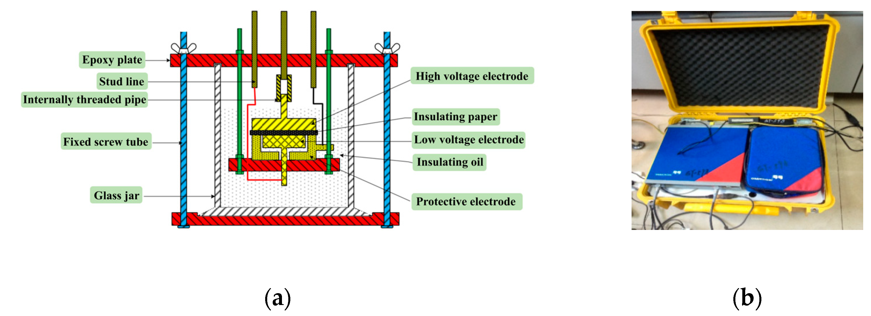
In this study, we used the three-electrode test cell and DIRANA dielectric response analyzer to conduct the FDS measurements. To conduct the FDS test, the prepared pressboard samples were placed in the three-electrode test cell, as shown in Figure 3. The three-electrode test cell mainly consisted of the high-voltage electrode, measurement electrode, and protection electrode. The high-voltage electrode and measurement electrode both use a cylindrical structure. The test frequency of the DIRANA Dielectric Response Analyzer is set to a range of 0.05 mHz to 5 kHz, and the test temperature is set to 30 °C. The FDS measurements were obtained after the internal and external temperatures reached equilibrium.

2.4. Accelerated Thermal Aging Experiments

Accelerated thermal aging experiments were carried out on the pretreated oil-immersed insulating pressboards with different moisture contents in a thermal aging chamber where the mass ratio of insulating cardboard to insulating oil was 1:10 and the aging temperature was set at 90 °C, 110 °C, or 130 °C. When the aging temperature is 90 °C or 110 °C, the aging time is 380 days. When the aging temperature is 130 °C, the aging time is 60 days. Insulating pressboards with different aging states were obtained by setting different aging times, as illustrated in Figure 4. After the accelerated thermal aging experiment, the insulating oil was sampled and tested for furfural content. Finally, the insulating pressboards with different aging degrees were disassembled and sampled, which were then used to measure the polymerization degree (DP) using the NCY series automatic test.

3. Average Polymerization Degree Evaluation of Insulating Pressboard Based on Furfural Content

It has been shown that the insulation life of a transformer is halved if the temperature increases by about 6 °C [33,34]. The polymerization degree (DP) indicates the aging state of insulating paper [35,36]. Furfural analysis can accurately and effectively assess the aging state of insulating paper based on the furfural content in oil [37]. Figure 5 shows the change rule of furfural concentration through time [38].
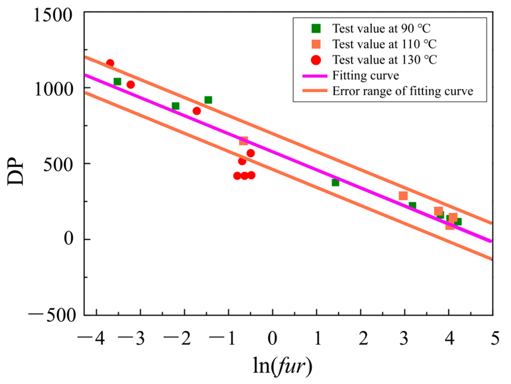
A semi-logarithmic linear relationship exists between furfural concentration and DP, Equation (1) was used to determine the average DP of insulating paper [38].
D P = a × ln f u r + b
From the relationship obtained between furfural content in oil and DP at 90 °C, 110 °C, and 130 °C, Equation (1) was fitted using the least squares fitting method. It was also assumed that there was a 5% error in the measurements; therefore, the corresponding fitted curves could be obtained by fitting the data at a confidence level of 95% using the least squares fitting method. The fitted curve of furfural content versus DP is shown in Figure 6.
Therefore, the relationship between furfural content in oil and DP of insulating paper can be obtained, as shown in Equation (2) [38]. The fitted values of each parameter are shown in Table 1.
D P v = 115.82 log F a + 567.85
On the other hand, DP can also be obtained using the FDS method. The dielectric loss factor Stanδ(f) can effectively reflect the changes in the aging of the transformer oil-paper insulation system, which is the integral value of the dielectric loss tanδ in a certain frequency band. The frequency range was from 1 mHz to 0.1 Hz. The dielectric loss factor is expressed as Equation (3) [39]. The relationship between DP and dielectric loss factor Stanδ(f) of insulating paper is shown in Equation (4) [39].
S tan δ ( f ) = 10 3 10 1 tan δ ( f ) d f
D P = 487.91445 + 944.42928 e S tan δ ( f ) / 0.00793

4. Calculation of Hotspot Temperature under Different Oil Circulation Cooling Modes

The hotspot temperature of the transformer is also related to its cooling mode. The cooling mode mainly has natural oil circulation cooling mode (ON), forced oil circulation cooling mode (OF), and forced oil circulation-oriented cooling mode (OD). The calculation of hotspot temperature under these operation modes has its characteristics; the specific calculation process is shown in the following formula. In this paper, Equations (6), (9), and (13) are the hotspot temperature calculation formulas for ON, OF, and OD, respectively. Their detailed calculation processes are shown in Section 4.1, Section 4.2 and Section 4.3, respectively.

4.1. Natural Oil Circulation Cooling Mode

For the natural oil circulation cooling mode, the winding hotspot temperature θ h is equal to the sum of the ambient temperature, the temperature rise of the top oil, and the difference between the winding hotspot temperature and the top oil temperature, as presented in Equations (5) and (6) [40].
θ T O = θ a + Δ θ T O r 1 + R K 2 1 + R x
θ h = θ T O + Δ θ H T O = θ a + Δ θ T O r 1 + R K 2 1 + R x + H g r K y
where the subscript capital (such as T O ) indicates the steady-state quantity, and the subscript r indicates the quantity under the rated load. θ α indicates the ambient temperature when the transformer is running. θ T O is the steady-state value of the oil temperature at the top of the windings. Δ θ T O r is the temperature rise of the oil temperature at the top of the windings when the rated load is applied. R is the ratio of the short-circuit loss to the no-load loss of the transformer. K is the loading coefficient of the transformer. Δ θ H T O is the temperature difference between the winding hotspot temperature and the oil on the top of the winding under arbitrary load. H g r is the temperature difference between the winding hotspot and the oil on the top of the winding under-rated load. x is the exponential power of the oil temperature rise, and its value is 0.9. y is the exponential power of the winding temperature rise, and its value is 0.6.

4.2. Forced Oil Circulation Cooling Mode

For the forced oil circulation cooling method, the oil flow through the winding is divided into two parts: between the winding exterior and the tank wall, where most of the oil flows, and between the magnetic circuit and the winding longitudinal cooling tank, where only a small part of the oil flows. Therefore, the top oil temperature is the combined temperature after the two oil flows intersect. The hotspot temperature of the transformer winding is directly related to the temperature distribution of the oil flow through the inside of the winding, as illustrated in Equations (7) and (8) [40],
θ B O = θ a + Δ θ B O r 1 + R K 2 1 + R x Δ θ T O B O = 2 Δ θ T o r Δ θ B O r K y
θ h = θ T O + Δ θ H T O = θ a + Δ θ B O r 1 + R K 2 1 + R x + 2 Δ θ T o r Δ θ B O r K y + H g r K y
where θ B O is the steady-state value of the bottom oil temperature, Δ θ B O r is the temperature rise of the bottom oil at the rated load, Δ θ T O B O is the difference between the temperature rise of the top and the bottom oil at any load, and the others are the same as the natural oil circulation cooling method. In this mode, the value of x is 1.0, and the value of y is 1.6.

4.3. Forced Oil Circulation Guided Cooling Mode

The forced oil circulation guided cooling mode calculation is the same as that of the cooling mode, with the load factor K 1 . For load factors K > 1 , a correction value was also added, as shown in Equation (9) [40],
θ h ( K > 1 ) = θ h ( K > 1 ) + 0.15 θ h ( K > 1 ) θ h r K = 1
where θ h ( k > 1 ) is the corrected hotspot temperature of the winding after considering the influence of wire resistance when K > 1 , θ h ( K > 1 ) is the calculated value of the hotspot temperature of the winding without considering the influence of wire resistance when K > 1 , and θ h r ( K = 1 ) is the calculated value of the hotspot temperature of the winding under rated conditions.
The accelerated aging factor FAA for a given load factor and ambient temperature was defined in IEEE Std C57.91™-2011 using 110 °C as a reference value for the hotspot operating temperature, as illustrated in Equation (10) [35].
F A A = exp 1500 383 1500 θ h + 273
The equivalent accelerated aging factor FEQA for a given time and temperature cycle is shown in Equation (11) [35],
F E Q A = n = 1 N F A A n Δ t n n = 1 N Δ t n
where Δ t n is the nth time interval in hours, and F A A n is the accelerated aging factor within Δ t n .
Finally, the average hotspot temperature θ ¯ h during the monitoring time t can be computed as shown in Equation (12).
θ ¯ h = 1500 1500 383 ln F E Q A 273

4.4. Simulation of Temperature Field in a Forced-Directed-Oil and Forced-Air Cooled (ODAF) Transformer

This study uses COMSOL Multiphysics 5.6 software to model oil-immersed transformers under various cooling modes. The modeling process is mainly divided into two parts. The first part consists of the construction of an electromagnetic field simulation model to solve the magnetic flux distribution of the transformer, as well as the size of core loss and winding loss, as the initial heat source for the temperature field simulation model of the transformer. The second part consists of building a simulation model for a temperature fluid coupling field under different cooling modes and calculating the temperature field distribution and hotspot location of the internal winding, iron core, and so on, of the transformer under each cooling mode.
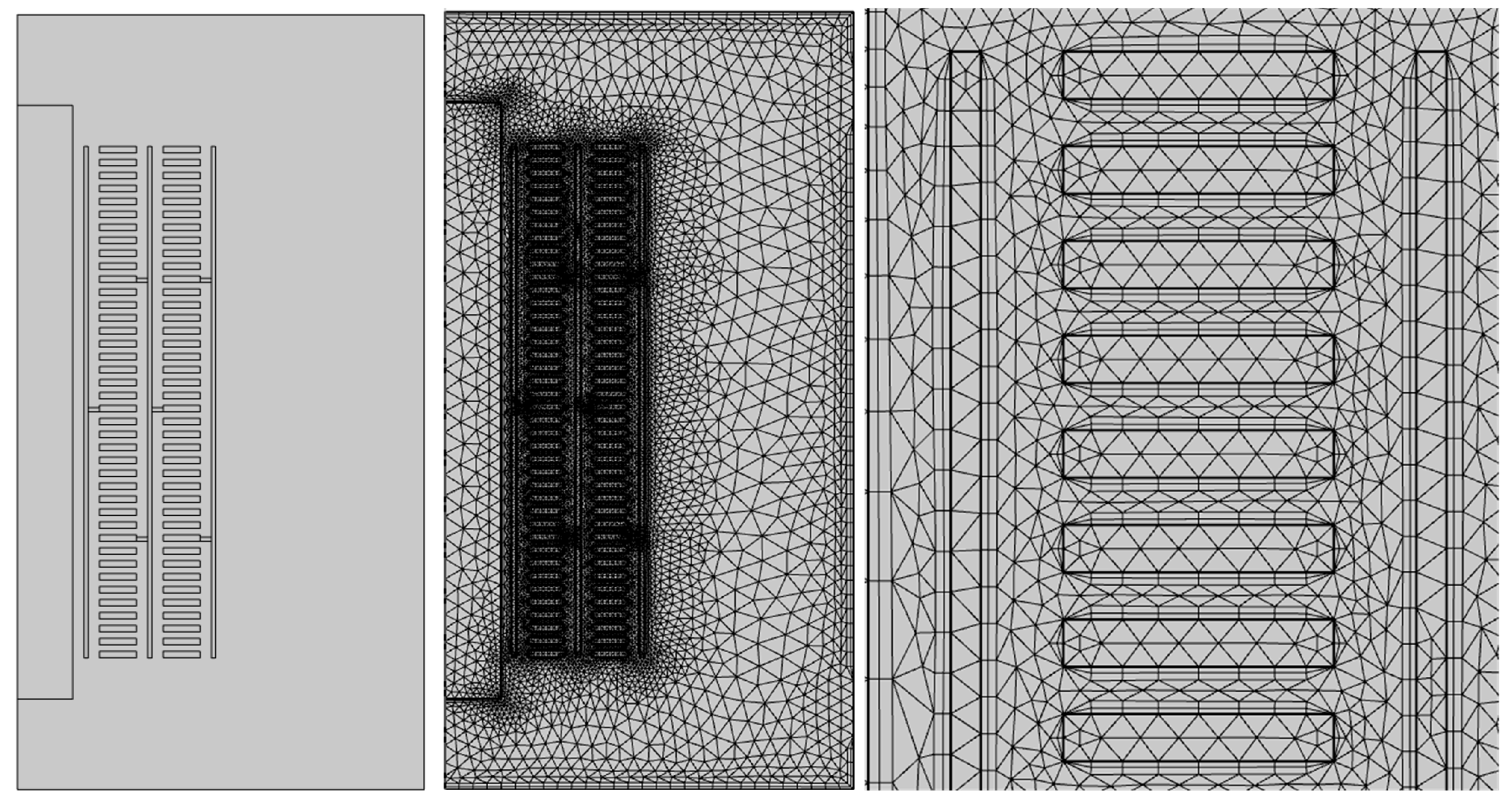
The simulation model of the oil-immersed transformer and its grid division are shown in Figure 7, as a cross-section of a symmetrical structure. By rotating Figure 7 along the axis of symmetry, a three-dimensional simulation structure of the transformer winding and insulation can be obtained. The simulation structure was built using a 1:1 ratio of real transformer windings. The physical parameters of windings, insulation materials, and transformer oil are shown in Table 2, all of which are equivalent to the material parameters of a real transformer. The approximate formula for calculating the viscosity Vi of the insulating oil is shown in Equation (13) [41],
V i = 0.0306 0.00007 T
where T is the temperature of the insulating oil, and k is its unit.
As the main heat dissipation medium inside transformers, transformer oil is a key factor that affects the temperature field distribution characteristics and heat dissipation efficiency inside transformers. The conservation equations of mass, momentum, and energy control its flow process. In this study, we constructed a two-dimensional axisymmetric model of the transformer by taking into account the symmetry of the main structure of the transformer; the corresponding control equation expression is represented by Equations (14)–(16) [41].
1 r r u r r + u z z = 0
ρ u r u r r + ρ u z u r z = p r + 1 r r μ k r u r r + z μ k u r z ρ u r u z r + ρ u z u z z = p z ρ g + 1 r r μ k r u z r + z μ k u z z
ρ c p u r T r + ρ c p u z T z = z λ T z + 1 r r λ r T r + P s
The static pressure p in the fluid boundary layer consists of two parts: the static pressure p at the reference point and the dynamic pressure pr caused by fluid motion. Given that p >> pr [41],
p z = ρ g
ρ u r u z r + ρ u z = ρ ρ g + 1 r r μ k r u z r + z μ k u z z
where p is the transformer oil density at the reference point, and (pp)g is the thermal buoyancy.
We used the Boussinesq approximation to reduce the solution’s nonlinearity and avoid the convergence problem caused by density evaluation. The Boussinesq approximation includes the following two aspects: (1) Only the variation of fluid density in the buoyancy term ρg of the equation is considered, with the remaining terms as constants, and (2) the difference in fluid density is directly proportional to the temperature difference.
Therefore, the volume expansion coefficient of the fluid αp is expressed as Equation (19) [41],
α p = 1 V ( V T ) p = 1 ρ ( ρ T ) p 1 ρ ρ ρ T T
where V is the volume of the fluid boundary layer; Equation (20) is obtained by substituting the above equation into Equation (18) [41],
ρ u r u z r + ρ u z u z z = α p g T T + 1 r r μ k r u z r + z μ k u z z
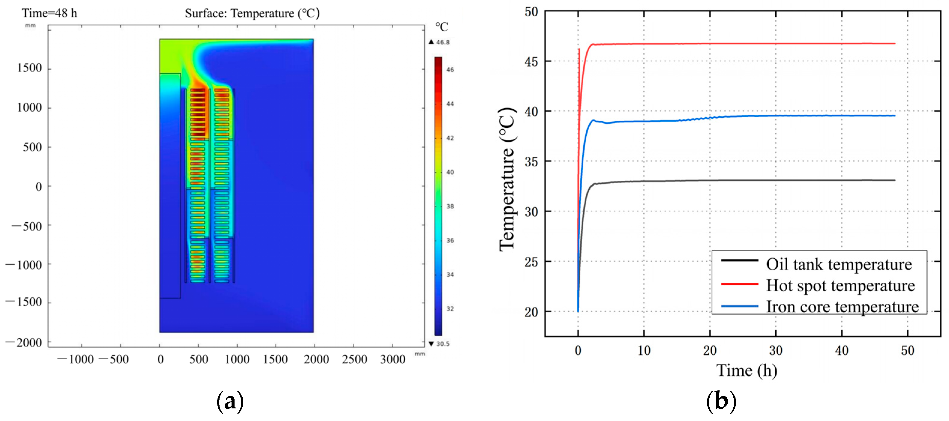
Figure 8 shows the cloud map of the internal temperature field distribution of an ODAF transformer under steady-state conditions. For transformers that use forced guided heat dissipation, the overall temperature of the wire cake shows an upward trend in each guide zone of the winding, and the temperature of the internal winding is higher than that of the external winding. The temperature increases toward the top of the transformer, and the hotspot is located in the middle and upper parts of the low-voltage winding, as shown in Figure 8a. Due to the slow oil flow in the transverse oil passage between turns of the winding, oil flow hysteresis can occur. The existence of oil baffles can hinder the movement of oil flow in the axial oil passage through forced driving, forcing the oil flow to exchange heat with the wire cake through the transverse oil passage as the flow path. Under a certain flow rate, the narrowing of the oil passage accelerates the flow rate of the oil flow, further optimizing the heat dissipation effect of the transformer oil.
In addition, the hotspot temperature of the transformer is 46.8 °C, with a minimum temperature of 30.5 °C. The temperature is 29.1 °C lower than the hotspot temperature observed in the methods mentioned above (75.9 °C), and the minimum temperature is also significantly reduced by 66.2 °C. Compared with the temperature rise curve, the forced guided oil circulation air cooling method improved the efficiency of heat exchange output due to the presence of an oil pump which was based on the original oil-immersed air cooling. The slope of the rising section of the transformer temperature rise curve becomes steeper and quickly reaches a stable value, indicating that this method has a significant effect in suppressing transformer temperature rise.
Compared to the transformer simulation model that did not consider the guiding effect of the oil baffle and the hysteresis phenomenon of the transverse oil channel, a significant temperature gradient was observed at the upper and lower ends of the transformer winding that considered the guide plate (Figure 8). Considering the guiding effect of the oil baffle on the oil flow, the temperature of the wire cake shows a steep upward trend. Due to the oil flow blocking effect of the oil baffle, it is difficult to dissipate local heat quickly, resulting in the transformer temperature reaching its maximum value and a steep slope of the temperature rise curve.
Figure 9 shows the oil velocity distribution of an ODAF transformer. Compared to the simulation calculation results without oil baffles, the maximum oil flow velocity at the center point of the inter-turn oil passage after considering the oil baffles increased from 0.0561 m/s to 0.268 m/s, and the corresponding point flow velocity increased by about 4 times compared to the flow velocity before the oil baffles were set. Moreover, the amplification effect of the transverse oil passage near the oil baffles was most pronounced. Thus, it can be seen that the existence of oil baffles reduces the occurrence of “dead oil zones”. Due to the strong coupling relationship between oil flow velocity and heat transfer coefficient, as the inter-turn oil passage velocity increases, the heat obtained from the contact between the oil flow and the wire cake transfers to the vertical oil passage on the other side of the wire cake with a high flow velocity, avoiding local overheating caused by the accumulation of heat in the transformer oil at low flow rates. Figure 8 and Figure 9 show that the highest temperature of the wire cake in the guide zone occurred near the oil channel with a low flow rate. This suggests that it is important to consider the oil baffle and the transverse oil passage between turns to accurately calculate the temperature rise in the transformer winding.

5. Moisture Evaluation of Insulating Papers Based on FDS Technology

This section focuses on the theoretical analysis of the FDS test results, the extraction of dielectric characteristic parameters, and the assessment method of the moisture content of insulating paper.

5.1. Effect of Moisture Content on the FDS Curve

The relative dielectric constant εr of the transformer primary insulation consisting of transformer oil and cellulose insulation satisfies the Kiusius-Mosotti (K-M) equation, as shown in Equation (21) [42],
ε r 1 ε r 2 = N α 3 ε 0
where εr is the relative dielectric constant. N is the number of polar particles per unit volume of the dielectric, α is the polarizability of the dielectric (F·m2), the physical quantity is the correlation coefficient related to the nature of the constituent particles of the dielectric, and ε0 is the vacuum dielectric constant, with the value of ε0 being equal to 8.85 × 10⁻¹² F/m. Given that water is a strong polar particle, an increase in moisture content leads to an increase in the number of conductive particles per unit volume of the sample, which leads to greater relaxation of the transformer’s main insulation system such that its relative dielectric constant εr becomes larger as shown in Equation (21).
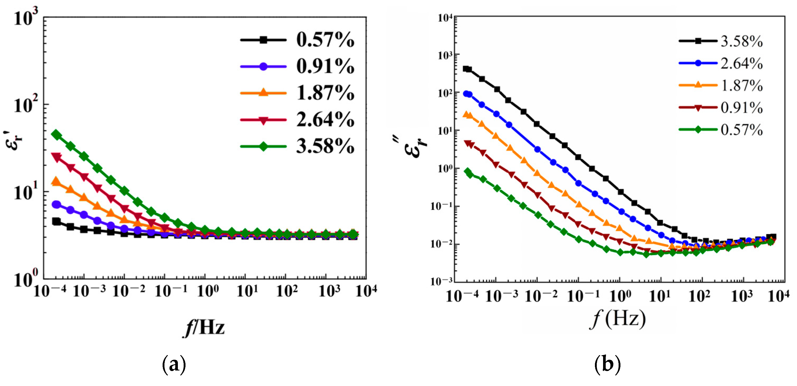
Figure 10 shows the complex relative permittivity ε*r of oil-impregnated insulating paperboard at different moisture contents. Both the real and imaginary parts of the complex relative dielectric constant increase with an increase in moisture content. Moreover, the influence of moisture on the complex relative dielectric constant is higher in the low-frequency range than in the high-frequency range. As the frequency increases, the influence of moisture on the real and imaginary parts of the complex relative dielectric constant significantly decreases. In the high-frequency range, an increase in moisture content does not impact the real and imaginary parts of the complex relative dielectric constant. As shown in Figure 10, when the moisture content of the oil-paper insulating samples is certain, εr and εr increase significantly in the frequency bands between 2 × 10⁻⁴ and 100 Hz and between 2 × 10⁻⁴ and 102 Hz, respectively. This phenomenon is mainly due to the dipole steering polarization which allows sufficient oil-paper intercalated interfacial polarization. With an increase in frequency, the dipole steering polarization and the polarization of the interlayer interface are gradually weakened, and εr and εr decrease in the frequency bands between 100 and 5 × 10³ Hz and between 102 and 5 × 10³ Hz, respectively, finally converging to the same level.
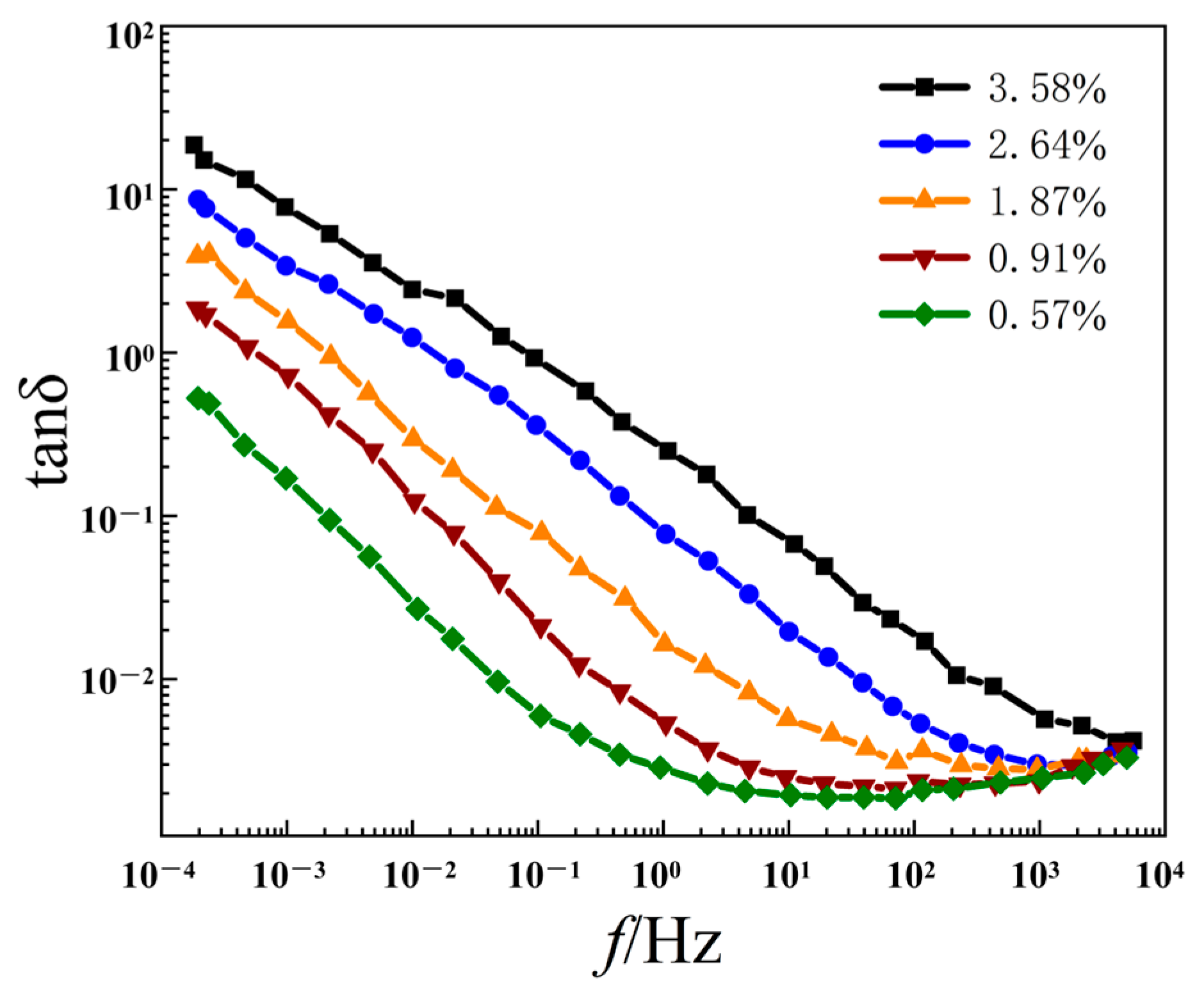
Figure 11 shows the tanδ of oil-impregnated pressboard at different moisture contents. An increase in moisture content of the insulating pressboard also affected the dielectric loss tanδ. As the moisture content increased, the dielectric loss of the insulating cardboard also increased. The impact of moisture on dielectric loss is mainly observed in the mid-frequency range, while in the low-frequency range, the impact of moisture on dielectric loss is significantly reduced. In the high-frequency range, the increase in moisture content of the insulating cardboard has almost no effect on dielectric loss. In addition, tanδ increases with an increase in moisture content. The complex relative permittivity ε*r and tanδ of oil-immersed paperboard at different moisture contents show that the low-frequency bands of ε*r and tanδ of the oil-paper insulation samples increase with an increase in moisture content, and the low-frequency bands of ε*r and tanδ of the oil-paper insulation samples can directly reflect the moisture content.

5.2. Parameter Extraction Method of Frequency Domain Spectroscopy Characteristic

Figure 10 and Figure 11 show that moisture content affects the oil-impregnated pressboard εr and tanδ under different frequency ranges, according to which the moisture content of the oil-impregnated insulating pressboard can be evaluated separately. The definitions and meanings of the FDS characteristic parameters for evaluating the moisture content of oil-immersed paper insulation are provided in Table 3 and Table 4.

5.3. Assessment of Moisture Content

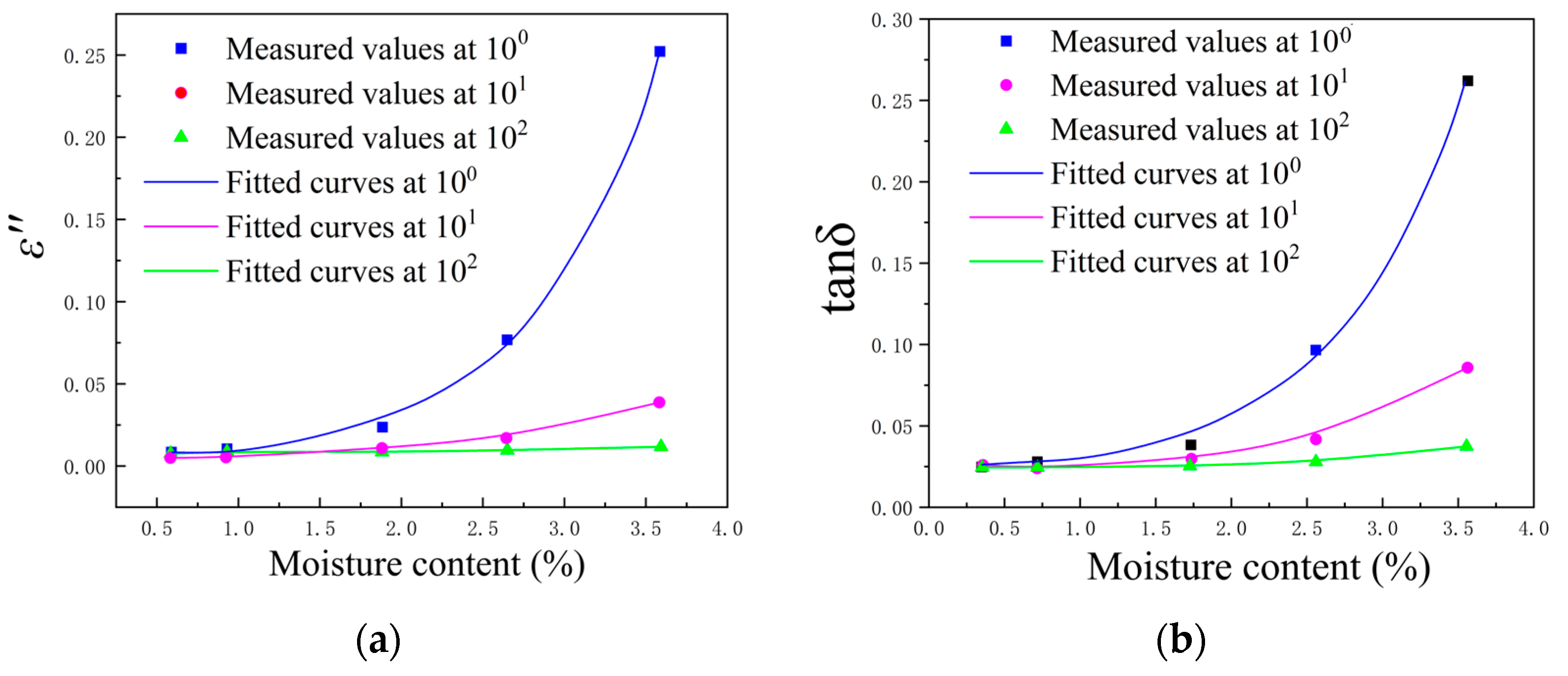
Since εr and tanδ closely follow the moisture content Km.c. of the insulating pressboard in the range of 100 to 102 Hz, 100 Hz, 101 Hz, and 102 Hz were selected as the characteristic frequencies for moisture evaluation. After analyzing the relationships between εr, tanδ, and moisture content at the characteristic frequencies in Figure 12, it was found that εr and tanδ were exponentially correlated to the moisture content of the insulating pressboard. The specific relationships are shown in Equations (22) and (23),
K m . c . = A × exp ε r × B + C
K m . c . = A × exp tan δ f × B + C
where Km.c. is the moisture content, εr and tanδ are the imaginary parts of the complex relative permittivity and the dielectric loss factor at the characteristic frequency, and A, B, and C are the fitting parameters (Table 5 and Table 6). At different characteristic frequencies, the exponential relationship between εr, tanδ, and the moisture content Km.c. has a high degree of goodness-of-fit. The fitting curves of the εr and tanδ are shown in Figure 12.

5.4. Moisture Assessment of On-Site Transformers

The oil-immersed transformer’s main insulation system consists of barriers, oil gaps, and spacers [43]. To reliably establish the frequency-domain dielectric mathematical model of the main insulation of an oil-immersed transformer and to better understand the relaxation process of the main insulation system of the transformer, the transformer insulation structure was simplified from the geometric principle to the X-Y model of the transformer’s oil-paper insulation system, which is very simple and has a clear physical meaning. X denotes the proportion of the baffle’s total effective thickness in the paper cylinder’s total effective thickness in the oil channel. Y denotes the proportion of the spacer’s total effective width to the spacer’s total effective width and the oil gap. In general, the value of X is between 0.2 and 0.5, and the value of Y is between 0.1 and 0.3.
Once the X and Y values of the oil-paper insulation system of a particular transformer have been determined, the FDS curves of the transformer’s main insulation system at a certain test temperature T can be calculated according to Equations (24) and (25) [44],
ε t o t * ω = 1 Y 1 X ε o i l * ω + X ε P B * ω + Y * ε P B * ω
ε o i l * ω = 2.2 j σ T ε 0 ω
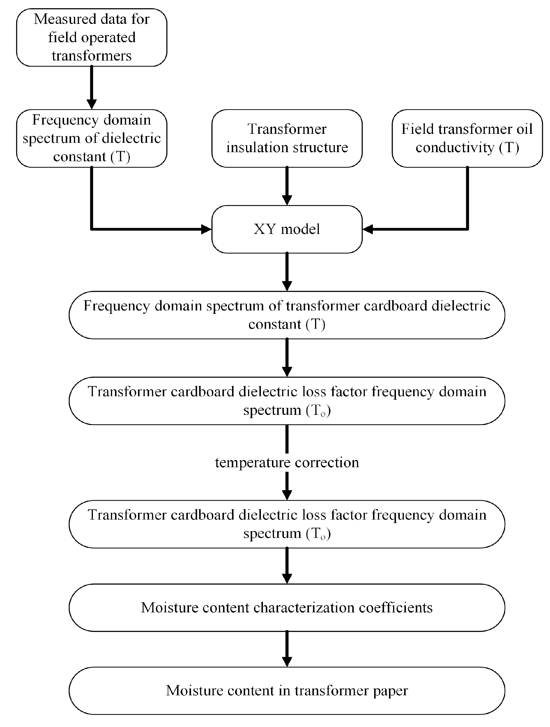
where ε*tot(ω) is the oil-paper insulation system’s effective complex relative permittivity frequency domain spectrum, ε*oil(ω) is the complex relative permittivity frequency domain spectrum of the oil, ε*PB(ω) is the complex relative permittivity frequency domain spectrum of the cellulose insulating material, σ(T) is the DC conductivity of the oil at the temperature T, and ε0 is the vacuum permittivity with the value of ε0 = 8.85 × 10⁻¹² (F/m). More than 99% of the water in oil-paper insulation exists in the solid insulation, while the proportion of water in the insulating oil is very small, so the focus of the quantitative assessment of the water content of transformer oil-paper insulation should be on its solid insulation. Figure 13 shows the flowchart for quantitatively evaluating moisture content using the frequency domain dielectric characteristic values mentioned in this paper.
If the micro-moisture content in the oil and real-time oil temperature data of the transformer are available, the moisture content in the insulation paper can be calculated based on the relationship between moisture in the oil and moisture in the paper fitted using ABB [45],
W p a p e r ( % ) = 2.06915 e 0.0297 t 1 × W o i l 0.0489 t 0.09733
where Wpaper is the moisture content in the paper, expressed in %, the moisture content in oil is expressed in mgH2O/kgOil, and t1 is temperature, expressed in °C.

6. Life Evaluation of On-Site Transformers under the Synergistic Effect of Multiple Factors

6.1. Insulation Life Assessment Model Considering the Effects of Moisture and Temperature

Moisture in insulating paper has a significant effect on transformer lifespan. Therefore, the life assessment model is used for life assessment under the combined influence of DP, temperature, and moisture content [38].
The kinetic equation for the cumulative loss of fiber polymerization is shown in Equation (27) [46],
ω D P = 1 D P D P 0 = ω D P * 1 e k D P t
where DP is the polymerization degree value after experiencing aging time t, and DP0 is the initial polymerization degree. The DP0 test results of the four initial moisture contents, 0.5%, 1%, 3%, and 5%, were 1180, 1187, 1168 and 1168, respectively. ω*DP denotes the ability of polymerization degree to degrade and save. kDP is the rate of cellulose polymerization degree degradation, 1/d. Mref = 0.5% was chosen as the reference, and a shift factor αM was obtained based on the time-temperature superposition of other main curves. The fitted value of ω*DP and kDP were 0.6991 and 2.04 × 10⁻³, respectively [46]. The relationship between αM and (M/Mref)0.773 can be represented as (28) [46].
α M = M / M r e f 0.773
The improved Arrhenius equation, which considers the effect of moisture content on the pre-exponential factor, is shown in Equation (29),
k = A M b exp E a R T
where DP0 is the initial degree of polymerization, tT is the time required for the polymerization degree to decrease to λDPt at temperature T and moisture content M, and the extrapolated equation for M is the lifetime model, as illustrated in Equation (30) [46],
α T = exp E ¯ a R 1 T r e f 1 T α M = M M r e f b α T , M = α T α M ω D P t = 1 D P t D P 0 t T r e f , M r e f = ln 1 ω D P t ω ¯ * D P / k ¯ D P t T , M = t T r e f , M r e f α T , M
where T is the average hotspot temperature value during the operating time of the transformer, A and Ea are related to the material properties and are obtained by accelerated aging tests in the laboratory based on the oil-immersed insulating pressboards, and M is the acceleration factor determined by the moisture content of the insulating paper.
The parameter values based on laboratory experiments are Ea = 91.4 kJ/mol, b = 0.773, R = 8.314 J/mol/K, Tref = 363 K, Mref = 0.5%, ω ¯ * D P = 0.699 , and k ¯ D P = 2.04 × 10 3 . To simulate the reliable operation of the transformer, is used due to the existence of the extreme polymerization degree λLODP [47] Equation (30) is only applicable when the value of the polymerization degree is greater than λLODP; therefore, the end-of-life value of the polymerization degree of the insulating paper is set to 400 to take into account the reliable operation of the transformer.
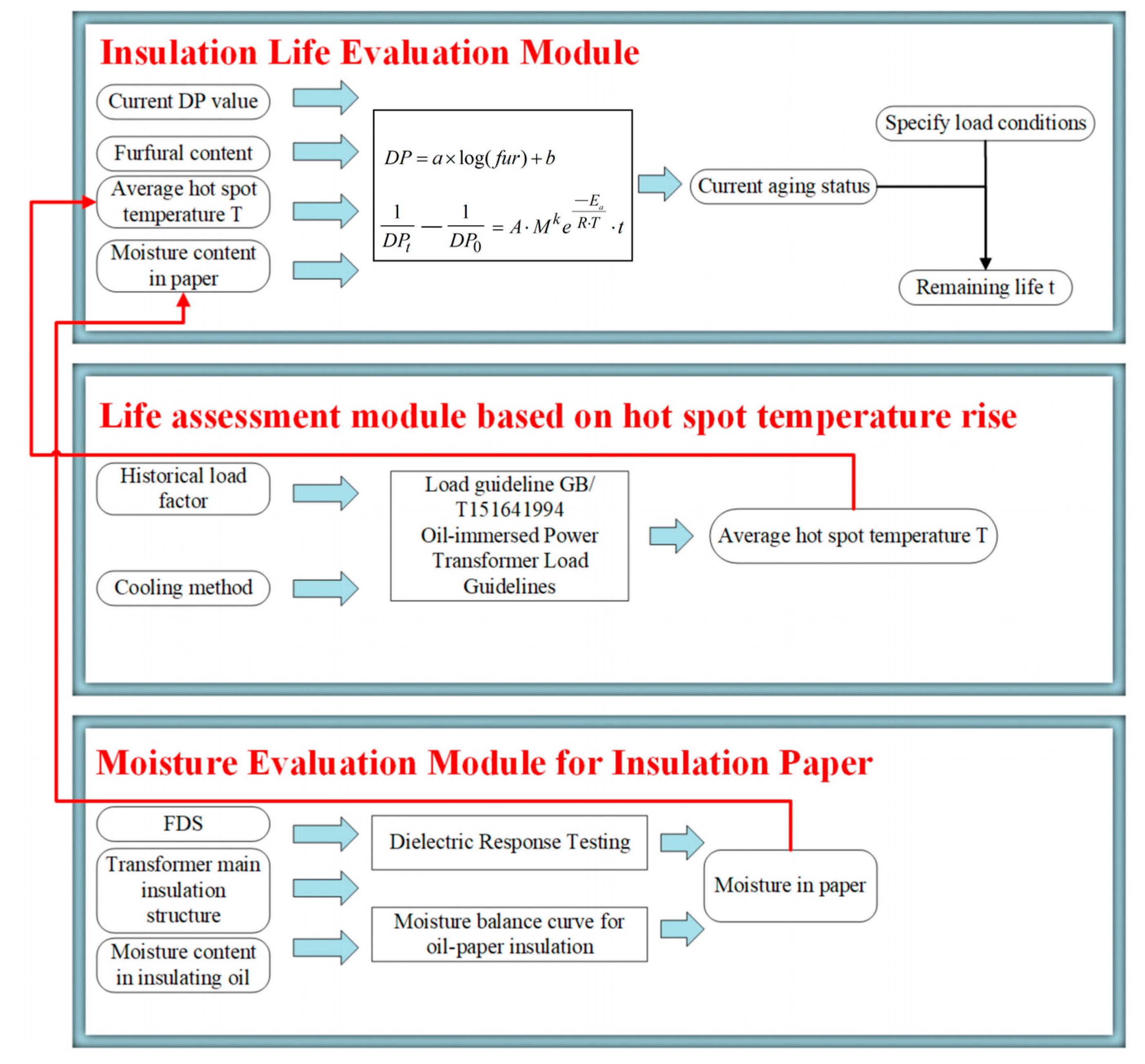
According to Equation (30), the time required for the polymerization degree to decrease from 1200 to 400 was calculated when the moisture in the paper was 0.2% and 2%, and the results are shown in Table 7. The flow process of the transformer life assessment method proposed in this paper is shown in Figure 14.

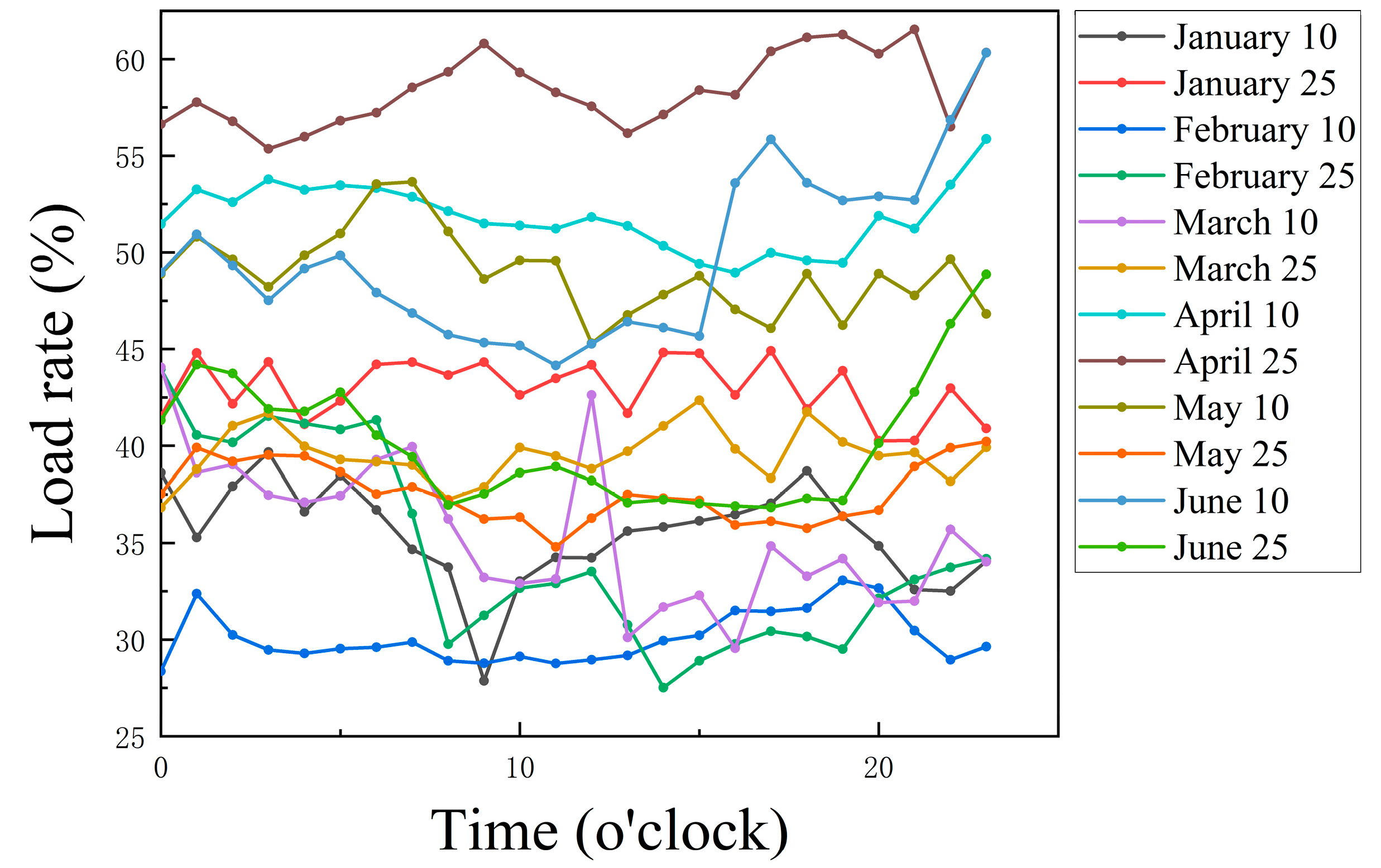
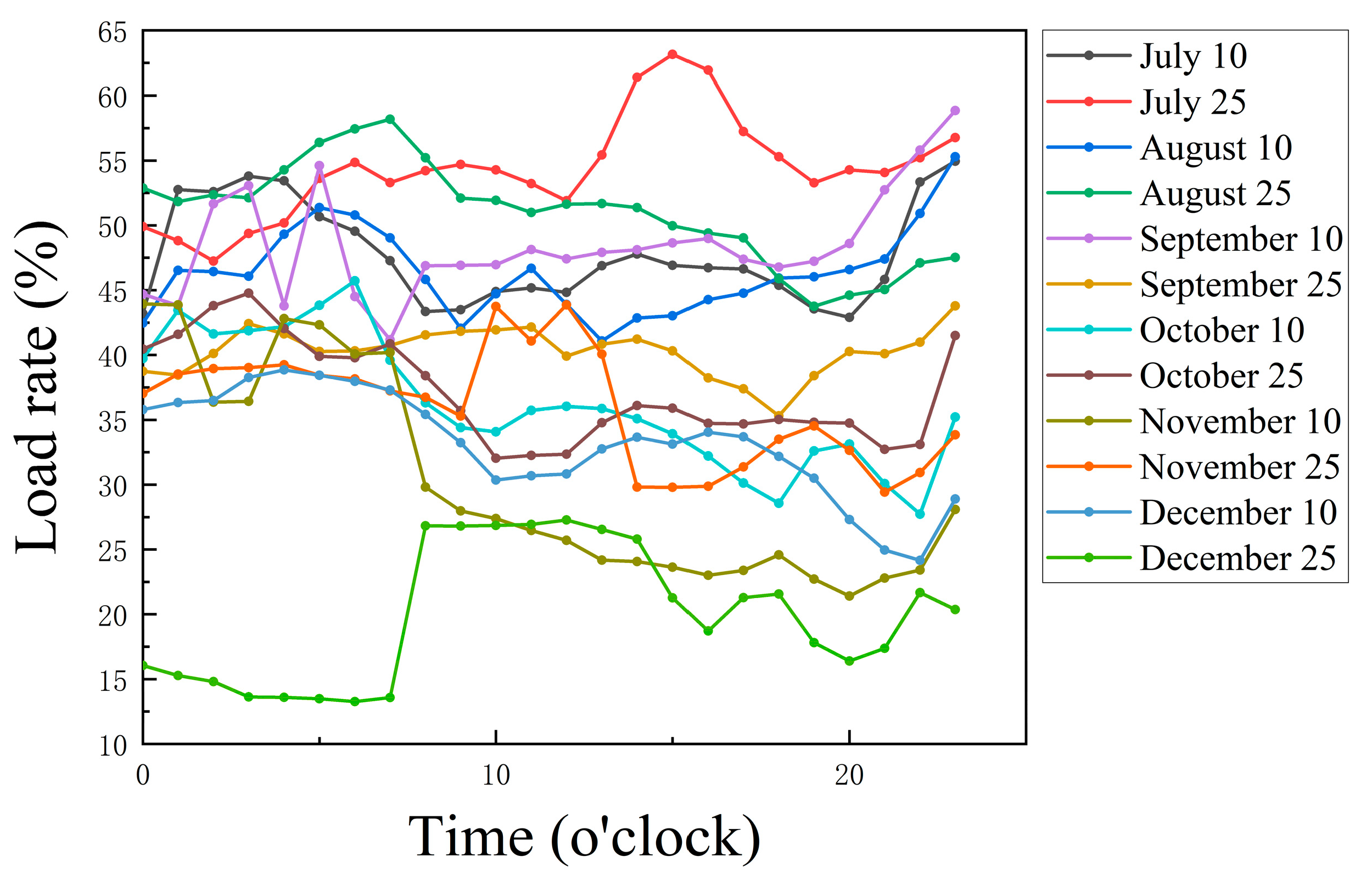
6.2. Example Validation I

A substation 500 kV No.1 main transformer phase A transformer was in operation in June 2004. The load rate of this phase transformer fluctuates greatly within a year. This paper only selected the load factor of the substation for 12 months in 2010 due to the large amount of data; for simplicity, day 10 and day 25 of each month were selected and a total of 24 observation points from 0:00 to 24:00 were chosen every day, as shown in Figure 15 and Figure 16. In addition, in 2010, for overhaul, after obtaining several DP measurements of the insulating pressboard, the average DP value of the transformer insulating cardboard was 866. The measured moisture content in the transformer oil was 5.5490 mg/kg, and the oil temperature was 72 °C. The average acceleration factor of the transformer was 0.409912, calculated according to Equations (10)–(13). The average hotspot temperature of the transformer was computed as 38.963 °C according to Equation (13) and the moisture in the paper of the transformer was 0.6982% according to Equation (26). Finally, the remaining lifespan of the transformer was found to be 9818.0 days or 26.8987 years, according to Equation (30). The transformer had been in operation for 6 years until 2010. According to the above calculations, it can be inferred that the transformer’s life cycle is about 32.8987 years. This is consistent with the conventional transformer operating lifespan of 30–40 years, which is consistent with the effectiveness of the proposed transformer life assessment model.

6.3. Example Validation II

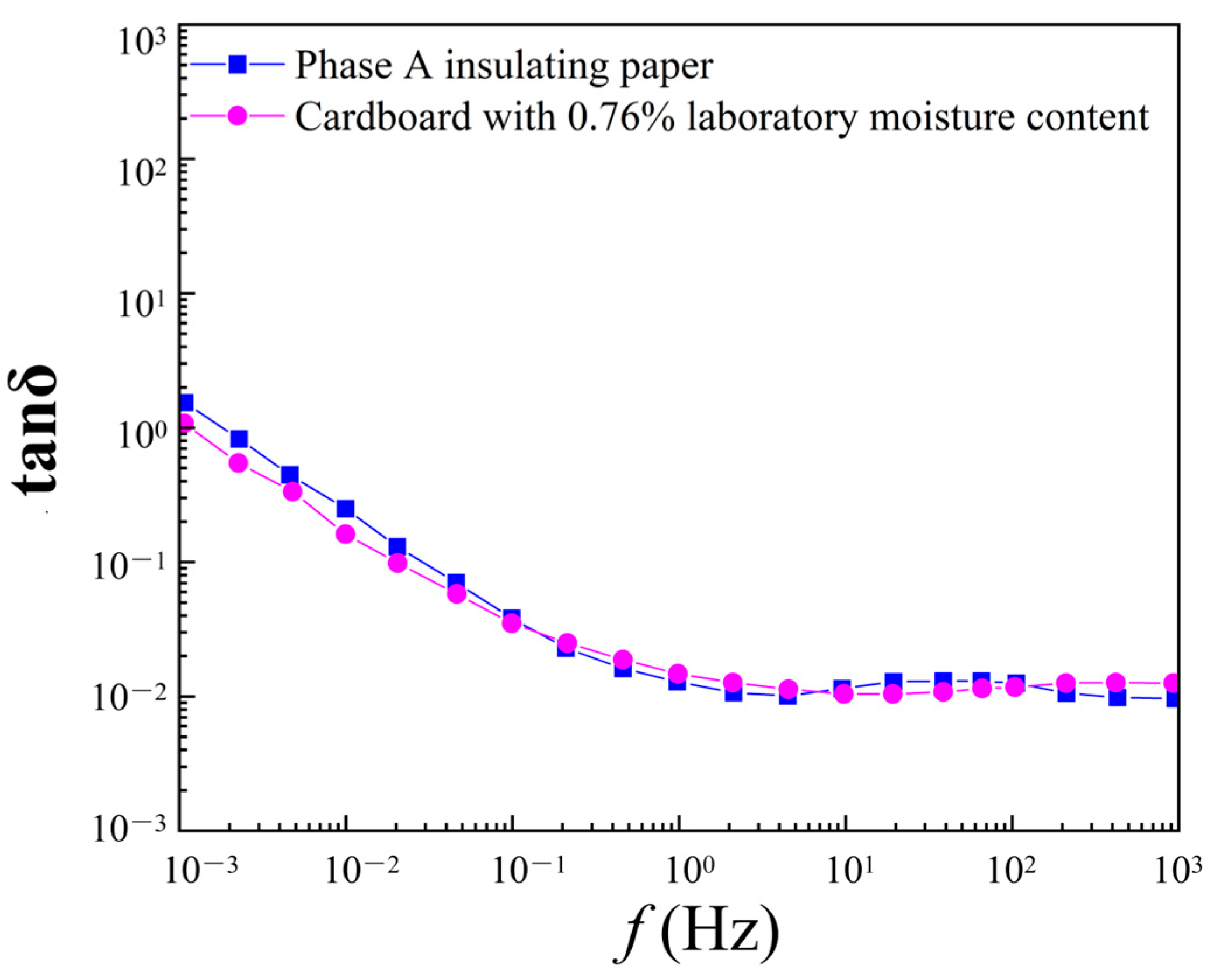
FDS testing was conducted on a main transformer that was shut down for maintenance in a certain substation to verify the effectiveness of the life evaluation method proposed in this paper. The transformer model was OSFPS-750000/500. The cooling mode was ODAF. The no-load loss was 244.6 kW. The load losses were 952.9 kW (high-medium), 326.1 kW (high-low), and 321.1 kW (medium-low). The A-phase transformer was put into operation in 1998 and had been running for 14 years until 2012, in the middle stage of its lifespan. The DP of the insulating pressboard was found to be 718 after hanging the transformer cover. In addition, according to the historical load conditions, the daily average load rate data (%) of the two typical months of the transformer in summer and winter are shown in Table 8. The annual average temperature was about 20 °C. The tanδ curve comparison between the A-phase transformer pressboard and the laboratory insulating cardboard with 0.76% moisture content is shown in Figure 17.
The dielectric loss factors at 100 Hz, 101 Hz, and 102 Hz (Figure 17) were selected and substituted into the fitted equations shown in Table 5 and Table 6, and the moisture contents were found to be 0.87%, 0.96%, and 0.97%, respectively. The average value of the two similar moisture contents was selected as the final diagnostic result, and the diagnostic result for the moisture content of the phase A transformer was 0.9%.
The average acceleration factor of the transformer was 0.52488, calculated according to Equation (19). The average hotspot temperature of the transformer was 55.8727 °C according to Equation (14). The moisture content in the transformer paper was found to be 0.9% based on the analysis of the FDS measurements. Finally, the residual insulation life of the transformer was 6097.4 days (16.7052 years) according to Equation (21). The transformer had been in operation for 14 years until 2012. Based on the above calculations, it can be inferred that the transformer’s life cycle is around 30.7052 years. The operating life of conventional transformers is 30 to 40 years, proving the effectiveness of the transformer life assessment model proposed in this paper.

7. Conclusions

To accurately predict the insulation life of on-site transformers, this paper proposed a new life assessment method for on-site transformers by considering the combined effects of moisture content and the oil circulation cooling method. The main conclusions are summarized as follows.
  • Based on the experimental data, the relationship between furfural content in oil and the polymerization degree of insulating paper was fitted, and a method for assessing the aging state of oil-paper insulation by furfural content in oil was proposed.
  • The FDS tests were conducted in the laboratory on oil-immersed insulating papers at different moisture contents. Then, the influence of the moisture content of the insulating paper on the FDS curve was analyzed, and the characteristic parameters were extracted to assess the moisture content of the paper quantitatively.
  • The time-temperature-moisture superposition method was introduced to improve oil-paper insulation’s accelerated thermal aging life prediction model. An on-site transformer life assessment method was established based on the moisture content of insulating paper, transformer load under different oil circulation cooling modes, and the time-temperature-moisture superposition life evaluation model. This method can effectively estimate the transformer insulation life with little amount of transformer insulation information. After the on-site transformer example verification, it was shown that the proposed life assessment method has high feasibility and accuracy, which makes it suitable for practical application.
This study is novel due to the incorporation of the influence of oil circulation cooling mode and moisture content for proposing a new method to evaluate transformer life more accurately. In future research, more factors can be explored to comprehensively influence the assessment of insulation life. For example, the concentration of oxygen, small molecule acids, and small molecule alcohols in insulation paper and oil can affect insulation aging and lifespan assessment, which is necessary to evaluate the lifespan of insulation more accurately.

Author Contributions

Conceptualization, Z.L. and Y.F.; methodology, H.C.; software, Y.S.; validation, B.L. and K.L.; investigation, W.Z.; writing—original draft preparation, Z.S.; writing—review and editing, Y.Z.; visualization, B.L. All authors have read and agreed to the published version of the manuscript.

Funding

This work was financially supported by North China Power Engineering Co., Ltd. of China Power Engineering Consulting Group under Grant number JBGS2023-01.

Data Availability Statement

Data are contained within the article.

Conflicts of Interest

Authors Z.L., Y.F., H.C., Y.S., K.L., W.Z. and Z.S. were employed by North China Power Engineering Co., Ltd. of China Power Engineering Consulting Group. The remaining authors declare that the research was conducted in the absence of any commercial or financial relationships that could be construed as a potential conflict of interest.

References

  1. Jurgensen, J.H.; Nordstrom, L.; Hilber, P. Estimation of Individual Failure Rates for Power System Components Based on Risk Functions. IEEE Trans. Power Del. 2019, 34, 1599–1607. [Google Scholar] [CrossRef]
  2. Cheng, L.; Yu, T.; Wang, G.; Yang, B.; Zhou, L. Hot Spot Temperature and Grey Target Theory-Based Dynamic Modelling for Reliability Assessment of Transformer Oil-Paper Insulation Systems: A Practical Case Study. Energies 2018, 11, 249. [Google Scholar] [CrossRef]
  3. McNutt, W.J. Insulation Thermal Life Considerations for Transformer Loading Guides. IEEE Trans. Power Del. 1992, 7, 392–401. [Google Scholar] [CrossRef]
  4. Song, R.; Chen, W.; Yang, D.; Shi, H.; Zhang, R.; Wang, Z. Aging assessment of oil–paper insulation based on visional recognition of the dimensional expanded Raman spectra. IEEE Trans. Instrum. Meas. 2021, 70, 1–10. [Google Scholar] [CrossRef]
  5. Jin, L.; Kim, D.; Abu-Siada, A.; Kumar, S. Oil-Immersed Power Transformer Condition Monitoring Methodologies: A Review. Energies 2022, 15, 3379. [Google Scholar] [CrossRef]
  6. Islam, M.M.; Lee, G.; Hettiwatte, S.N. A Review of Condition Monitoring Techniques and Diagnostic Tests for Lifetime Estimation of Power Transformers. Electr. Eng. 2018, 100, 581–605. [Google Scholar] [CrossRef]
  7. Zhang, Y.; Li, Y.; Li, S.; Zheng, H.; Liu, J. A Molecular Dynamics Study of the Generation of Ethanol for Insulating Paper Pyrolysis. Energies 2020, 13, 265. [Google Scholar] [CrossRef]
  8. Yang, Q.; Su, P.; Chen, Y. Comparison of Impulse Wave and Sweep Frequency Response Analysis Methods for Diagnosis of Transformer Winding Faults. Energies 2017, 10, 431. [Google Scholar] [CrossRef]
  9. Huang, W.; Shao, C.; Dong, M.; Hu, B.; Zhang, W.; Sun, Y.; Xie, K.; Li, W. Modeling the Aging-Dependent Reliability of Transformers Considering the Individualized Aging Threshold and Lifetime. IEEE Trans. Power Del. 2022, 37, 4631–4645. [Google Scholar] [CrossRef]
  10. Liao, R.; Sang, F.; Liu, G.; Yang, L. Study on Neutral Acid and Water Dissolved in Oil for Different Types of Oil-paper Insulation Compositions of Transformers in Accelerated Ageing Tests. Proc. CSEE 2010, 30, 125–131. [Google Scholar]
  11. Sedighi, A.R.; Kafiri, A.; Sehhati, M.R.; Behdad, F. Life Estimation of Distribution Transformers Using Thermography: A Case Study. Meas. J. Int. Meas. Confed. 2020, 149, 106994. [Google Scholar] [CrossRef]
  12. Zhang, E.; Liu, J.; Zhang, C.; Zheng, P.; Nakanishi, Y.; Wu, T. State-of-Art Review on Chemical Indicators for Monitoring the Aging Status of Oil-Immersed Transformer Paper Insulation. Energies 2023, 16, 1396. [Google Scholar] [CrossRef]
  13. Ariannik, M.; Razi-Kazemi, A.A.; Lehtonen, M. An Approach on Lifetime Estimation of Distribution Transformers Based on Degree of Polymerization. Reliab. Eng. Syst. Saf. 2020, 198, 106881–106889. [Google Scholar] [CrossRef]
  14. Heywood, R.J.; Stevens, G.C.; Ferguson, C.; Emsley, A.M. Life Assessment of Cable Paper Using Slow Thermal Ramp Methods. Thermochim. Acta 1999, 332, 189–195. [Google Scholar] [CrossRef]
  15. Zou, X.; Uesaka, T.; Gurnagul, N. Prediction of Paper Permanence by Accelerated Aging I. Kinetic Analysis of the Aging Process. Cellulose 1996, 3, 243–267. [Google Scholar] [CrossRef]
  16. Heywood, R.J.; Xiao, X.; Ali, M.; Emsley, A.M. Degradation of Cellulosic Insulation in Power Transformers. Part 3: Effects of Oxygen and Water on Ageing in Oil. IEE Proc. Sci. Meas. Technol. 2000, 147, 115–119. [Google Scholar]
  17. Emsley, A.M.; Ali, M.; Xiao, X.; Heywood, R.J. Degradation of Cellulosic Insulation in Power Transformers. Part 4: Effects of Ageing on the Tensile Strength of Paper. IEE Proc. Sci. Meas. Technol. 2000, 147, 285–290. [Google Scholar] [CrossRef]
  18. Emsley, A.M. The Kinetics and Mechanisms of Degradation of Cellulosic Insulation in Power Transformers. Polym. Degrad. Stab. 1994, 44, 343–349. [Google Scholar] [CrossRef]
  19. Fan, X.; Yang, S.; Lai, B.; Liu, J.; Zhang, Y.; Wang, Z. Normalization for FDS of Transformer Insulation Considering the Synergistic Effect Generated by Temperature and Moisture. IEEE Access 2020, 8, 202013–202021. [Google Scholar] [CrossRef]
  20. Fofana, I.; Borsi, H.; Gockenbach, E. Results on Aging of Cellulose Paper under Selective Conditions. In Proceedings of the CEIDP, Kitchener, ON, Canada, 14–17 October 2001; pp. 205–208. [Google Scholar]
  21. Stevens, G.C.; Emsley, A.M. Review of Chemical Indicators of Degradation of Cellulosic Electrical Paper Insulation in Oil-Filled Transformers. IEE Proc. Sci. Meas. Technol. 1994, 141, 324–334. [Google Scholar]
  22. Vasovic, V.; Lukic, J.; Mihajlovic, D.; Pejovic, B.; Radakovic, Z.; Radoman, U.; Orlovic, A. Aging of Transformer Insulation—Experimental Transformers and Laboratory Models with Different Moisture Contents: Part I—DP and Furans Aging Profiles. IEEE Trans. Dielectr. Electr. Insul. 2019, 26, 1840–1846. [Google Scholar] [CrossRef]
  23. Medina, R.D.; Romero, A.A.; Mombello, E.E.; Rattá, G. Assessing Degradation of Power Transformer Solid Insulation Considering Thermal Stress and Moisture Variation. Electr. Power Syst. Res. 2017, 151, 1–11. [Google Scholar] [CrossRef]
  24. Saleh, N.; Azis, N.; Jasni, J.; Ab Kadir, M.Z.A.; Talib, M.A. Paper Lifetime Mathematical Modelling Based on Multi Pre-Exponential Factors for Oil-Immersed Transformer. Pertanika J. Sci. Technol. 2022, 30, 1115–1133. [Google Scholar] [CrossRef]
  25. Vasovic, V.; Lukic, J.; Mihajlovic, D.; Pejovic, B.; Milovanovic, M.; Radoman, U.; Radakovic, Z. Aging of Transformer Insulation of Experimental Transformers and Laboratory Models with Different Moisture Contents: Part II—Moisture Distribution and Aging Kinetics. IEEE Trans. Dielectr. Electr. Insul. 2019, 26, 1847–1852. [Google Scholar] [CrossRef]
  26. Ariannik, M.; Razi-Kazemi, A.A.; Lehtonen, M. Effect of Cumulative Moisture Content on Degradation of Transformer Paper Insulation. IEEE Trans. Dielectr. Electr. Insul. 2017, 24, 611–618. [Google Scholar] [CrossRef]
  27. Srinivasan, M.; Krishnan, A. Prediction of Transformer Insulation Life with an Effect of Environmental Variables. Int. J. Comput. Appl. 2012, 55, 43–48. [Google Scholar] [CrossRef]
  28. Teymouri, A.; Vahidi, B. Estimation of Power Transformer Remaining Life from Activation Energy and Pre-Exponential Factor in the Arrhenius Equation. Cellulose 2019, 26, 9709–9720. [Google Scholar] [CrossRef]
  29. Fan, X.; Liu, J.; Goh, H.H.; Zhang, Y.; Zhang, C.; Rahman, S. Acquisition of FDS for Oil-Immersed Insulation at Transformer Hotspot Region Based on Multiconstraint NSGA Model. IEEE Trans. Ind. Electron. 2022, 69, 13625–13635. [Google Scholar] [CrossRef]
  30. Fan, X.; Liu, J.; Lai, B.; Zhang, Y.; Zhang, C. FDS Measurement-Based Moisture Estimation Model for Transformer Oil-Paper Insulation Including the Aging Effect. IEEE Trans. Instrum. Meas. 2021, 70, 1–10. [Google Scholar] [CrossRef]
  31. Hernandez, G.; Ramirez, A. Dielectric Response Model for Transformer Insulation Using Frequency Domain Spectroscopy and Vector Fitting. Energies 2022, 15, 2655. [Google Scholar] [CrossRef]
  32. Fan, X.; Liu, J.; Zhang, Y.; Ding, Z.; Wang, Q. Polarization Loss Analysis and Ageing Characterisation of Transformer Oil-immersed Insulation by Using Decoupled Frequency Domain Spectroscopy. High Volt. 2022, 7, 575–585. [Google Scholar] [CrossRef]
  33. Martin, D.; Zare, F.; Caldwell, G.; McPherson, L. Calculating the Residual Life of Insulation in Transformers Connected to Solar Farms and Operated at High Load. IEEE Electr. Insul. Mag. 2020, 36, 10–20. [Google Scholar] [CrossRef]
  34. Zhou, L.; Wang, J.; Wang, L.; Yuan, S.; Huang, L.; Wang, D.; Guo, L. A Method for Hot-Spot Temperature Prediction and Thermal Capacity Estimation for Traction Transformers in High-Speed Railway Based on Genetic Programming. IEEE Trans. Transport. Electrific. 2019, 5, 1319–1328. [Google Scholar] [CrossRef]
  35. IEEE Std C57.91™-2011; IEEE Guide for Loading Mineral-Oil-Immersed Transformers and Step-Voltage Regulators. IEEE: New York, NY, USA, 2011.
  36. Su, Z.; Zhang, Y.; Du, Y.; Su, Y.; Deng, J.; Goh, H.H.; Yin, J.; Wang, G. An Enhanced X Model of Oil-Impregnated Paper Bushings Including Axial and Radial Nonuniform Thermal Aging. IEEE Trans. Dielectr. Electr. Insul. 2023, 30, 825–833. [Google Scholar] [CrossRef]
  37. Lin, Y.; Wei, C.; Tao, F.; Li, J. Aging Assessment of Oil-Paper Insulation of Power Equipment With Furfural Analysis Based on Furfural Generation and Partitioning. IEEE Trans. Power Del. 2019, 34, 1626–1633. [Google Scholar] [CrossRef]
  38. Yang, L. Study on Aging Characteristics of Oil-Paper in Transformer and Its Lifetime Estimation Method. Ph.D. Thesis, Chongqing University, Chongqing, China, 2009. [Google Scholar]
  39. Du, Y. Assessment of Moisture Status and Thermal Aging in Oil-Impregnated Paper Condenser Bushings Based on Frequency Domain Spectroscopy. Master’s Thesis, Chongqing University, Chongqing, China, 2017. [Google Scholar]
  40. GB/T 15164-1994; Loading Guide for Oil-Immersed Power Transformers. IEC Publishing: Geneva, Switzerland, 1994.
  41. Xiao, R. Temperature Field Simulation Modeling and Rapid Prediction Method of Real-time Temperature of Converter Transformer. Master’s Thesis, Chongqing University, Chongqing, China, 2022. [Google Scholar]
  42. Wang, Y.; Gao, J.; Liao, R.; Zhang, Y.; Hao, J.; Liu, J.; Ma, Z. Investigation of characteristic parameters for condition evaluation of transformer oil-paper insulation using frequency domain spectroscopy. Int. Trans. Electr. Energy Syst. 2015, 25, 2921–2932. [Google Scholar] [CrossRef]
  43. Fan, X.; Liang, F.; Luo, H.; Li, C.; Liu, J.; He, J. Adaptive-Optimization-Based Digital Simulation Database for Nonuniform Aging Diagnosis of Transformer Insulation System. IEEE Trans. Ind. Electron. 2023. [CrossRef]
  44. Liu, J.; Sun, T.; Fan, X.; Zhang, Y.; Lai, B. A Modified Simulation Model for Predicting the FDS of Transformer Oil-Paper Insulation Under Nonuniform Aging. IEEE Trans. Instrum. Meas. 2021, 70, 1–9. [Google Scholar] [CrossRef]
  45. Martins, M. Study of Moisture Equilibrium in Oil-Paper System with Temperature Variation. In Proceedings of the 7th International Conference on Properties and Applications of Dielectric Materials, Nagoya, Japan, 1–5 June 2003; Volume 3, pp. 1124–1129. [Google Scholar]
  46. Yang, L.; Deng, B.; Liao, R.; Sun, C.; Pu, J. Improvement of Lifetime Model on Thermal Aging of Oil-paper Insulation by Time-temperature-moisture Superposition Method. Proc. Chin. Soc. Elec. Eng. 2011, 31, 196–203. [Google Scholar]
  47. Yang, L.; Liao, R.; Sun, C.; Sun, H. Influence of Natural Ester on Thermal Aging Characteristics of Oil-Paper in Power Transformers. Eur. Trans. Electr. Power. 2010, 20, 1223–1236. [Google Scholar] [CrossRef]
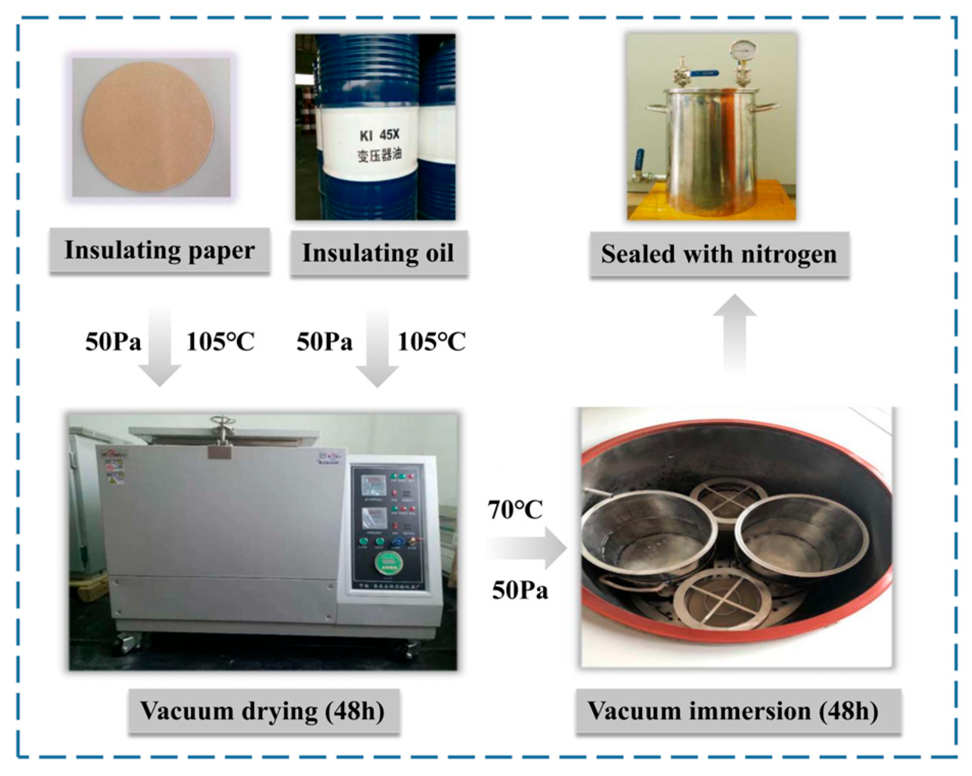
Figure 1. Pretreatment flow chart of experimental materials.
Energies 17 00429 g001
Figure 2. Moisture intrusion experimental process.
Energies 17 00429 g002
Figure 3. Frequency domain spectroscopy testing platform: (a) three-electrode test cell; (b) DIRANA dielectric response analyzer.
Energies 17 00429 g003
Figure 4. Schematic diagram of the aging experiment.
Energies 17 00429 g004
Figure 5. Relationship between furfural and aging time: at (a) 90 °C, (b) 110 °C, and (c) 130 °C.
Energies 17 00429 g005
Figure 6. Relationship between fur and DP.
Energies 17 00429 g006
Figure 7. The simulation model of oil-immersed transformer and its grid division.
Energies 17 00429 g007
Figure 8. Simulation on the ODAF transformer: (a) temperature distribution; (b) Temperature rise curve.
Energies 17 00429 g008
Figure 9. Simulation of the ODAF transformer: (a) 3D oil flow velocity diagram, (b) 3D local oil flow velocity diagram, and (c) 2D oil flow velocity map.
Energies 17 00429 g009
Figure 10. FDS of insulating pressboards at different moisture contents: (a) εr and (b) εr.
Energies 17 00429 g010
Figure 11. The tanδ of oil-immersed pressboards at different moisture contents.
Energies 17 00429 g011
Figure 12. Fitting relation: (a) εr value and moisture content and (b) tanδ value and moisture content.
Energies 17 00429 g012
Figure 13. Moisture assessment process for the transformer insulation paper.
Energies 17 00429 g013
Figure 14. The process flow of the transformer life assessment method.
Energies 17 00429 g014
Figure 15. Hourly load from January to June (day 10 and day 25).
Energies 17 00429 g015
Figure 16. Hourly load from July to December (day 10 and day 25).
Energies 17 00429 g016
Figure 17. The comparison of the tanδ curve.
Energies 17 00429 g017
Table 1. Fitting parameters and goodness of fit R2.
Confidence Level (Math.)Model ParameterSample Size (Statistics)R2
ab
100%−115.82567.85210.92
95%−135.50512.4521/
95%−96.05623.2521/
Table 2. Transformer material parameters.
MaterialComponentsDensity (kg/m3)Specific Heat Capacity (J/kg·K)Thermal Conductivity (W/m·K)
CopperTransformer
winding
8900385397
SteelTransformer
core
755045052
Epoxy resinInsulation layer93013400.19
Mineral oilInsulation oil87818810.13
AirOutside Air1.181006.30.026
Table 3. Characteristic parameters (εr) of moisture content.
ParametersMeaningMeaning Definition
εr (f = 100)The imaginary part of complex relative permittivity at f = 100 HzMoisture Content Characteristics
εr (f = 101)The imaginary part of complex relative permittivity at f = 101 Hz
εr (f = 102)The imaginary part of complex relative permittivity at f = 102 Hz
Table 4. Characteristic parameters (tanδ) of moisture content.
ParametersMeaningMeaning Definition
tanδ (f = 100)Value of dielectric loss factor at f = 10 Hz0Moisture Content Characteristics
tanδ (f = 101)
tanδ (f = 102)
Value of dielectric loss factor at f = 10 Hz1
Value of dielectric loss factor at f = 10 Hz2
Table 5. Fitting relation between moisture content and εr.
FrequencyFitting FormulaThe Goodness-of-Fit R2
100εr = 1.67 × 10⁻³ + 22.50 × 10⁻⁴ exp (1.32 × Km.c.)0.99
101εr = 4.37 × 10⁻³ + 6.17 × 10⁻⁴ exp (1.12 × Km.c.)0.99
102εr = 7.21 × 10⁻³ + 3.73 × 10⁻⁴ exp (0.72 × Km.c.)0.99
Table 6. Fitting relation between moisture content and tanδ.
FrequencyFitting FormulaThe Goodness-of-Fit R2
100tanδ = −5.74 × 10⁻³ + 28.90 × 10⁻⁴ exp (1.26 × Km.c.)0.99
101tanδ = 35.64 × 10⁻³ + 5.24 × 10⁻⁵ exp (1.36 × Km.c.)0.99
102tanδ = 2.07 × 10⁻³ + 0.75 × 10⁻⁵ exp (1.46 × Km.c.)0.99
Table 7. Results of experimental data.
Moisture Content (%)Temperature (°C)αT,MtDP=400 (Days)
0.2650.0528,680.0
750.1311,582.0
850.324705.3
950.742034.7
1051.63923.7
2650.314795.2
750.801890.7
851.92785.4
954.40342.2
1059.66155.8
Table 8. Sample values of the load factor.
August and December Load Factor for a Transformer
DatesLoad FactorDatesLoad FactorDatesLoad FactorDatesLoad Factor
1 August67.5608.0966.1808.1774.1008.2562.18
2 August63.0408.1068.5008.1872.3808.2671.43
3 August67.0708.1168.6108.1969.7508.2770.81
4 August60.1808.1264.3508.2070.9108.2867.70
5 August63.3608.1367.9308.2161.7308.2965.48
6 August69.8308.1465.1108.2264.9008.3069.07
7 August62.4808.1564.0608.2361.1708.3163.26
8 August54.3408.1667.6308.2450.94//
1 December50.1812.0947.0412.1752.8812.2555.48
2 December48.7812.1055.2712.1855.4412.2650.80
3 December46.9312.1146.4712.1952.7812.2749.95
4 December51.7712.1253.6012.2054.2312.2856.03
12 December45.6312.1346.4812.2153.6112.2956.96
6 December47.6812.1454.5312.2256.1012.3058.69
7 December53.2312.1557.1212.2352.8612.3162.90
8 December51.9312.1656.2212.2454.34//
Disclaimer/Publisher’s Note: The statements, opinions and data contained in all publications are solely those of the individual author(s) and contributor(s) and not of MDPI and/or the editor(s). MDPI and/or the editor(s) disclaim responsibility for any injury to people or property resulting from any ideas, methods, instructions or products referred to in the content.