1. Introduction
Batteries serve as the power source for electric vehicles (EVs), so heat is always generated in both charging and discharging states. This heat accumulates within the module battery pack, which has a negative impact on the battery. The accumulated heat not only affects the battery’s operational efficiency, it also reduces its lifespan. If the accumulated heat within the module battery is too high, thermal runaway can occur, which leads to explosions and potential fires [
1,
2,
3,
4,
5].
The battery thermal management system (BTMS) plays a crucial role in the efficient operation of the battery pack, yielding a longer lifespan. It also serves as a protective system against explosions and battery fires resulting from heat accumulation. This has encouraged many researchers to develop BTMSs using different cooling methods as proposed by Olabi et al. [
6] and Luo et al. [
7]. Their aim was to maintain the BTMS temperature at approximately 15–35 °C, which is recognized as the suitable operating temperature of Li-ion batteries [
6,
7,
8].
At lower ambient temperatures, a passive cooling method can be applied to the BTMS. This passive cooling method does not require electricity energy for operation as reported by Faraj et al. [
9] and Arshad et al. [
10]. The heat pipe is widely used for the passive cooling method. However, there are some limitations when using the passive cooling method. First, it is quite difficult to control the BTMS temperature at the desired temperature range due to the free convection mechanism. Second, it is not suitable for working at high ambient temperatures. Third, it requires a larger area for performing heat transfer.
Studies by Akinlabi et al. [
11], Wang et al. [
12], and Chen et al. [
13] concentrated on the air-cooled technique for the BTMS using force convection. This method depends on the ambient air temperature and air velocity. Hence, at high ambient temperatures, it was unable to work efficiently because the module temperature was too high. Therefore, some researchers employed the water-cooled method to absorb heat from the module battery pack as proposed by Jouhara et al. [
14], Kalaf et al. [
15], Siruvuri and Budarapu et al. [
16], and Siruvuri et al. [
17]. These researchers used a liquid pump, a storage tank, and a finned-tube heat exchanger to transfer heat to the surroundings. Water is pumped to cool down the BTMS module, and the heat from the battery is then expelled to the surroundings using a finned-tube air-cooled heat exchanger. This method still has limitations due to ambient temperatures and may not be suitable for use at quite high ambient temperatures. This problem was solved by some researchers by adding a small chiller machine to produce chilled water at the desired temperatures, which allows the BTMS temperature to be controlled precisely. The use of a chiller system allows precise control of the cooling plate temperature, enhancing the accuracy and efficiency of heat transfer. This leads to better control of heat dissipation rates. However, the use of chilled water for cooling occasionally produces a non-uniform temperature in the BTMS module at a higher heat rate due to the sensible heat transfer. This results in a greater difference in temperature between battery cells (should not exceed 5 °C [
18]), which affects the power capacity and lifespan of the battery. Additionally, of note, the use of a chiller for the BTMS requires a refrigeration system and water storage for system operation. This results in a more complex system operation than that used for other cooling techniques. Additionally, the use of electricity for this cooling system is an important factor when applied for real use in EVs.
Alternatively, some researchers have proposed a direct refrigerant cooling system for the BTMS, including Hong et al. [
19], Wang et al. [
20], Cen et al. [
21], and Gillet et al. [
22]. In their studies, the BTMS is powered using a vapor compression refrigeration system, and the refrigerant is applied to the cooling plate for heat absorption. This cooling plate is designed to allow the liquid refrigerant from the refrigeration system to be directly expanded through the cooling plate. Hence, it subsequently works as an evaporator that can absorb the accumulated heat from the module battery pack. The experimental works by Ren et al. [
23], Chen et al. [
24] and Cao et al. [
25] also indicated that the thermal management by the direct refrigerant cooling is efficient and requires less electrical energy compared to water-based cooling systems. Additionally, this system has the potential to be integrated into the vehicle’s air conditioning system (providing multi-cooling purposes). This is possible because of the dual-evaporator vapor compression refrigeration system. However, there are some limitations when using the BTMS-DRC. First, it is quite difficult to control the temperature of the cooling plate at the optimal range. This will produce a temperature that is too low for the BTMS, which has a negative impact on battery performance. Second, the difference in temperature between battery cells is too great (exceeds 5 °C) due to the problem of heat absorption. This is a challenge in this research field. Third, the precise control of the refrigerant flow rate through the BTMS to achieve the proper working BTMS temperature is a problem to be further addressed, representing a research challenge.
As the refrigerant flows through the BTMS (which involves flow equipment with a small channel), if the refrigerant flow rate is high enough, the flow evaporation of the two-phase fluid will occur within the refrigerant-side cooling system (small channel or small tubes are mostly used) [
26,
27,
28,
29]. Hence, the heat transfer from batteries to the refrigerant occurs under the saturated temperatures of the refrigerant while flowing through the BTMS (working as an evaporator). This process is associated with latent heat transfer due to the two-phase refrigerant being evaporated inside. Thus, it is possible to achieve better temperature uniformity in the BTMS, which is the main achievement of BTMS development. Hence, direct refrigerant cooling under the evaporation process is recognized as an alternative method to achieve the uniformity of the BTMS temperature. However, this cooling technique still requires an experimental proof and simulation technique for efficient design and temperature uniformity prediction. This is a major research gap and challenge in this research area. Moreover, for a larger scale design, it essentially requires an alternative simulation technique that can simplify the two-phase flow evaporation at the refrigerant tube-side cooling. In this case, the heat transfer performance of the two-phase flow evaporation through the refrigerant tube side can be represented by the convective heat transfer coefficient under a certain saturation temperature as supported by numerous studies [
26,
27,
28,
29]. Hence, the flow evaporation at the refrigerant side can be modeled by the convective heat transfer mechanism when the h
ref is specified. With the convection heat transfer mechanism, the design of the BTMS based on direct refrigerant cooling is possible based on the finite element method for convection heat transfer. This can help researchers to develop a larger scale BTMS based on efficient refrigerant cooling. However, from literature surveys, the simulation technique for the BTMS based on direct refrigerant cooling with flow evaporation at the refrigerant side, which is represented by the convection heat transfer, has not been proposed. Moreover, an experimental proof of it has not been available, and this proof is useful for validating the simulated results in which the temperature uniformity under certain conditions of battery heat generation is a major concern. This is a research gap in this research area.
As previously noted, this study aims to propose a simulation technique to investigate the performance of the BTMS based on direct refrigerant cooling under various operating conditions. The refrigerant, R134a, is used for investigation. The efficient design of the BTMS based direct refrigerant cooling is explored and discussed. The heat transfer from batteries to the refrigerant occurs under the saturated temperatures of the refrigerant flowing through the BTMS. This process is associated with latent heat transfer due to the two-phase refrigerant being evaporated inside. This mechanism allows for better temperature uniformity in the BTMS, which is the main achievement of BTMS development. Hence, direct refrigerant cooling under the evaporation process is recognized as an alternative way to achieve the uniformity of the BTMS temperature. This information is not available in the literature. However, this cooling technique still requires an experimental proof and simulation technique for efficient design and temperature uniformity prediction. This is a major research gap and challenge in this present work. The refrigerant side cooling, which is the result of the two-phase flow evaporation, is simplified to be the convection heat transfer, which is represented by the convection heat transfer mechanism (or evaporation heat transfer [
30,
31]). The developed BTMS-DRC is proposed, and the thermal management performance is discussed. The temperature uniformity under various working conditions is explained. The simulation results are validated with the experimental results, which were obtained under the same working conditions. This is to prove the proficiency of the simulation technique. An experimental test bench based on dual-evaporators vapor compression refrigeration system is employed for results validation. The developed BTMS module (20 cells) is fabricated to examine its cooling performance. Even though this paper presents both simulation techniques and experimental proof, the major concern is to employ the simulation techniques for efficiently investigating BTMS-DRC performance. The experimental results are only used to validate the simulated results to ensure that the modelling is developed correctly. Full experimental studies on the BTMS-DRC will be proposed in the next publication by the authors.
2. Development of Simulation Modelling and the Experimental Setup
2.1. Cycle Description and Refrigerant Flow State Based on DE-VCR
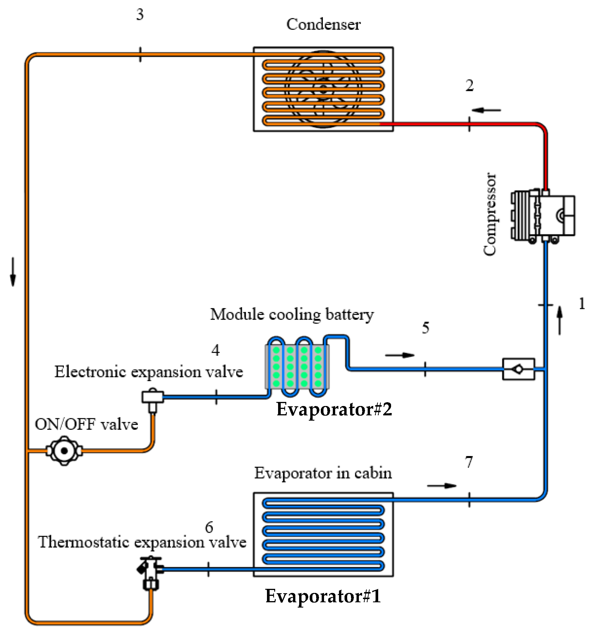
As mentioned earlier, the aim of this paper is to demonstrate the thermal management performance of the developed BTMS via direct refrigerant cooling. Hence, the expansion process of the refrigerant from high side pressure to low side pressure is key to the thermal performance of the BTMS because the BTMS functions as the evaporator. The vapor compression refrigeration system is then employed for this application. Since the BTMS requires a relatively low cooling capacity, a dual-evaporator vapor compression refrigeration system (DE-VCR) can be applied. The DE-VCR is also used to demonstrate the refrigeration performance when simultaneously working for both air conditioning and the BTMS. A schematic diagram is shown in
Figure 1.
As shown in
Figure 1, the role of evaporator #1 is to produce cold air for air conditioning in EVs. Meanwhile, evaporator #2 functions as the BTMS, which aims to maintain the module temperature of between 15 and 35 °C depending on the heat generation rate from the battery. During operation, the low-pressure vapor from the two evaporators (states 5 and 7) is mixed before entering the compressor suction line (state 1). Later, it is compressed via the compressor to produce the superheated vapor at the compressor’s discharge (state 2). The superheated vapor is condensed within the condenser by rejecting heat to the surroundings. The liquid refrigerant coming out of the condenser (state 3) undergoes the expansion process through the expansion valve of each evaporators (states 4 and 6) to complete the cycle operation.
As the refrigerant flows through the BTMS, if the refrigerant flow rate is high enough, the flow evaporation of the two-phase fluid will occur within the refrigerant side (small channel or small tubes are mostly used). Hence, the heat transfer from the batteries to the refrigerant occurs under the saturated temperatures of the refrigerant as it flows through the BTMS (evaporator #2). This process is associated with latent heat transfer due to the evaporation of the two-phase refrigerant inside. Thus, it is possible to achieve temperature uniformity for the BTMS, which is the main achievement of BTMS development. Hence, direct refrigerant cooling under the evaporation process is recognized as an alternative method to achieve BTMS temperature uniformity.
2.2. Development of BTMS Based on the Direct Refrigerant Cooling
As explained above, the method to achieve BTMS temperature uniformity is made possible by means of promoting the flow evaporation of the two-phase refrigerant through the BTMS. Thanks to the refrigerant properties that can evaporate within the small tube or narrow gap, it is feasible to design a BTMS with small flow channels for refrigerant flow. Thus, it is easier to apply the refrigerant to the module to promote temperature uniformity and heat absorption. As a result, the heat transferring area between the refrigerant and modules is as large as possible.
When operating the direct refrigerant cooling, the two-phase refrigerant enters the manifold at the bottom. This can ensure that all of the inserted tubes are flooded by the refrigerant. This results in producing approximately the same mass flow rate for each tubes. Therefore, the refrigerant velocity of each tube is approximately the same. As explained earlier, the flow evaporation at the refrigerant tube side can be simplified to be the convection heat transfer. This is made possible when the convection heat transfer coefficient and the saturation temperature are specified. The flow parameters and the physical properties of the refrigerant are key to determining them. Hence, at the refrigerant tube side, the Reynold number, Prandtl number and Nusselt number can be determined using Equations (1)–(4).
The Nusselt number under the flow evaporation of the R134a refrigerant can be initially estimated using the Dittus-Boelter correlation equation [
32]. In this study, the Li-ion battery (version 18650) is selected for investigation because it is widely used and provides efficient power capacity. This battery is based on a cylindrical shape. The heat transfer mechanism between the battery and the refrigerant is based on the conduction heat transfer through the selected solid material, which is different from that reported in many published works (mostly based on convection by air). The problem of water condensation (due to moist air) at relatively low cooling temperatures is relieved (the condensation of water typically occurs at temperatures less than 23 °C under hot and humid conditions).
For these reasons, the BTMS is designed as shown in
Figure 2, and twenty five small holes (diameter of 9.525 mm) are made along the length of the main module. The main module is fabricated from aluminum alloy (AA-1060). The battery is installed vertically within the socket as shown in
Figure 2. Hence, the height of the module is consistent with the length of battery. The overall size of the BTMS depends on the number of battery cells. In this present study, the heat generation must be simulated by the battery heat simulator (BHS). It is fabricated from the wired heater, which aims to precisely control the heat load for performance assessment. The wired heater is installed within the cylindrical rod, which has similar size as the Li-Ion battery (18650). The details of its construction will be presented in
Section 2.4 (experimental setup).
The cooling performance of the developed BTMS will be investigated to demonstrate the working temperature under various heat generation and operating conditions. The main purpose is to numerically predict the temperature of the module and its temperature uniformity. Previous studies [
2,
3,
18] recommend that the temperature difference in the module should not be greater than 5 °C and that the appropriate working temperature of the BTMS must be 15–35 °C. These criteria are considered for the cooling performance assessment. The simulation is aimed to employ the numerical techniques to predict the BTMS temperature so that the desired working conditions are satisfactory based on the working criteria. Hence, an advantage of the simulation is being able to optimize the desired parameters, cooling capacity, materials used, and heat transfer mechanisms.
2.3. Developing the BTMS Model for Simulation
In this section, the modeling assumptions and strategy for developing the BTMS model are explained. The BTMS dimension is based on the design criteria proposed in the previous section and is modeled using the commercial software package SOLIDWORKS (version 2021 SP3.0). The procedures to create the physical model and apply the mathematical model are proposed.
2.3.1. Modelling Assumptions and Working Conditions
According to the developed BTMS, heat is generated at the core of battery and dissipates to the outer surface of the battery, which has a certain surface area. For a certain state of charging or discharging (C-rate), heat accumulation within the battery varies with time even when the C-rate is kept constant. Therefore, there is a maximum heat generation rate for a certain C-rate at a specified discharging/charging rate. This present work then selects the highest possible heat generation under various C-rates to design the BTMS and the refrigeration system. This is regarded as the worst case for design. If the BTMS operates efficiently under the worst case scenario, it also ensures that the BTMS can efficiently operate under various working conditions. Therefore, the constant heat rate is assumed to simplify the finite element modelling so that a more realistic heat transfer process is implemented.
In this study, the constant rate of heat generation is set based on the constant heat flux during the simulation and experiment as supported by previous studies, including Wang et al. [
33], Ikramov et al. [
34], and Xu et al. [
35]. This generated heat flux will transfer to the module using the conduction heat transfer mechanism at the contact area between the battery surface and the module housing.
For refrigerant side cooling, the two-phase fluid enters the small tubes as shown in
Figure 2 and subsequently undergoes the evaporation process when absorbing heat from the batteries. Latent heat transfer is involved during the evaporation process. This is possible when the refrigerant flow rate is adequately high and the expansion pressure ratio through the expansion valve is appropriately regulated. This scenario is useful to obtain the constant refrigerant temperature when operated at the saturated state. The saturation temperature is associated with the pressure during the flow evaporation, as supported by previous studies by Kim et al. [
28], Wang et al. [
29], and Ramadan et al. [
30]. In addition, the flow evaporation of the refrigerant can be simplified to be based on the convection heat transfer process as supported by previous studies [
28,
29,
30,
31]. However, it is well known that the two-phase flow phenomenon through the small channels during the evaporation process makes it difficult to correctly develop simulation models. This is because the non-equilibrium evaporation and heat and mass transfer between phases are involved. Such flow phenomena are very complicated, and it is difficult to predict the flow physics accurately. However, regarding the evaporation heat transfer, the parameter that represents the convection heat transfer process is the convective heat transfer coefficient. This parameter can be estimated theoretically and can later be proved by the experiment (Moon et al. [
36] and Li et al. [
37]). This makes the evaporation heat transfer prediction more accurate.
In the present study, the heat transfer performance and temperature uniformity of the BTMS are the main focuses, while the flow characteristics of the two-phase fluid are not a major concern. Therefore, the refrigerant side cooling can be simplified to be based on the convection heat transfer mechanism in which the saturation temperature and mass flow rate are key to determining the convective heat transfer coefficient.
The outer surface of the BTMS is designed to be well insulated so that it is independent of the ambient temperature variation. Hence, there is assumed to be no heat loss or gain between the outer surface and the surroundings.
2.3.2. Geometries and Grid
The geometrical drawings of the developed BTMS are shown in
Figure 3. The three-dimensional (3-D) models are created using the commercial software SOLIDWORKS (version 2021 SP3.0). The dimensions are obtained from the drawing of the BTMS module. The 3-D model is used to simulate by the finite element method. Hence, the grid elements are generated using the software so that all governing equations can be solved numerically. In this work, the grid independent test is also implemented. Herein, three levels of grid elements, coarser (approximately 39,000), medium (approximately 99,200) and fine (approximately 255,000) are created. Thus, the simulated results (solution) can later be proven to be independent of the number of grid elements (grid independence test). The trigonal bipyramid is selected for this work, which is consistent with the physical problem as supported by [
33,
34,
35].
2.3.3. Heat Transfer Modeling and Boundary Conditions
The mathematical model for the heat transfer mechanism based on conduction and convection is applied to the BTMS models. As explained previously in
Section 2.1, the refrigerant side is simplified to the evaporation heat transfer, which is based on the convection heat transfer model when the evaporation convective heat transfer coefficient is known. Therefore, the finite element method for convection is applied to the refrigerant side. Meanwhile, heat generated by the battery is transferred to the refrigerant using the conduction mechanism. In this case, the heat generated by the battery is assumed to exhibit a constant heat flux (the ratio of the heat generation to the surface area of battery) to be consistent with the boundary conditions provided by software so that the solution is predicted accurately. The wall surface of the BTMS model is assumed to be well insulated (no heat loss or heat gain). All governing equations used for the simulation are stated in Equations (5)–(8). Meanwhile, the thermophysical properties of the solid material and fluid used (R134a refrigerant) are provided in
Table 1 and
Table 2.
For the convection heat transfer models, the saturation temperature of the refrigerant and heat transfer coefficient are key to predicting the temperature of the BTMS model. These two parameters are delivered by means of controlling the refrigerant flow rate and evaporation pressure, which is regulated by the expansion valve (for practical use). Hence, these parameters can be considered as the control variables for the simulations because they are under the control of the investigator. Therefore, the variation of the saturation temperature and heat transfer coefficient will be considered for the parametric study. This will be presented in the
Section 3.
For the heat flux boundary condition, the weak form is expressed as follows:
For the boundary condition based on the convection heat transfer, the weak form is expressed as follows:
The adiabatic boundary condition is expressed as follows:
Here, , , and are the thermal conductivities of the material used.
Q is the source term representing internal heat generation.
h is the convective heat transfer coefficient.
n is the unit normal vector.
Ta is the prescribed ambient temperature.
q is the prescribed heat flux.
For the heat transfer based on the heat conduction, the thermal conductivity of the selected material is key to producing the working temperature of the BTMS. Hence, the type of materials used is a parameter of interest for this work. In this case, these types of materials are considered in the parametric study as tabulated in
Table 1.
2.4. Experimental Setup
The dual-evaporator vapor compression refrigeration system test bench was designed and built for this study. It is used to obtain the experimental results for validation of the simulated results under the same working conditions. The temperatures at the point of interest on the BTMS module are used to validate the accuracy of the simulation model. The criteria to select the major hardware for constructing the test bench are based on practical use in EVs. These criteria are used to prove that the commercially available hardware can later be adapted for real use in EVs. A schematic diagram and photograph of the test bench are shown in
Figure 4.
The compressor used has a nominal cooling capacity of 12,000 btu/h. It is a reciprocating type designed specifically for use in EVs. The compressor is electrically driven by a DC motor with a 24 VDC power supply. The condenser is an air-cooled condenser in which the fan speed can be controlled precisely to maintain the condensation pressure at the desired point. This condenser is designed for a common use in conventional automobiles and EVs. The condenser is a mini-channel finned-tube heat exchanger.
Evaporator #1 is used to produce cold air simulating the air conditioning of the EV cabin. It is modified from a commercial automotive fan-coil unit. The fan-coil unit is installed within the weathering chamber to demonstrate the air-conditioned space. To simulate the cooling load for achieving the thermal comfort conditions, the air heater is installed within the weathering chamber. The heater power is up to 3000 W, and the heat load is controlled precisely using a variable transformer (220VAC) with an uncertainty of 1.0% (read value).
Evaporator #2 is designed to work as the BTMS as explained in the previous section. The cooling performance of the BTMS is the main focus of this present study. To efficiently provide the cooling performance assessment of the BTMS, the battery heat simulator (BHS) is fabricated so that the heat generation can be regulated precisely for performance assessment. This is not possible for the real Li-ion battery (version 18650) in which the heat generation varies significantly with the state of charge or discharge. In this work, the shape of the battery heat simulator is designed to be similar to the real battery, and its dimensions are consistent with the battery Li-ion (18650). The wired heater is installed along the axis; thus, the heat generated then dissipates from the core of the BHS to the outer surface. This phenomenon is similar to that noted for the real battery. The detailed design of the battery heat simulator is shown in
Figure 5.
A variable transformer (0–220VAC) is used to apply the heat load to the BHS. Hence, the steady state operation for the heat transfer process can be achieved for further validation with the simulation case. In this work, the heat generated ranges from 80 to 320 W for the entire module. The reason for and proof of the heat transfer capacity of the newly designed battery module housing based on the combined conduction–convection heat transfer mechanism will be proposed and discussed clearly. This information is provided as evidence of the maximum cooling capacity in which the newly designed battery module housing functions under an appropriated working temperature (15–35 °C). Herein, at 320 W of heat generated for the whole module, each BHS cell produces 16 W of heat. Meanwhile, at 80 W of heat generated, each cell produces 4 W of heat. For the case with 80 W of heat generated, the demonstration of heat generation from the battery Li-ion (version 18650) working at the C-rate is investigated as supported by [
5]. This scenario is recognized as the worst case for the design of the thermal management system when using Li-ion battery version 18650.
The refrigerant flow rate and the working pressure of the refrigerant side cooling of the BTMS is controlled using the electronic expansion valve (EEV). This allows the desired working pressure and temperature of the BTMS to be controlled precisely.
The temperature at the point of interest is measured using type-k thermocouples and based on the measuring surface temperature with an uncertainty of 1.5% of the read value. The temperature values are recorded continuously using a data logger. Hence, transient and steady state operations can be observed clearly. The pressure value at points of interest are detected by a pressure transducer (uncertainty of 1.0% FS) and a pressure gauge, which are calibrated before being installed into the test bench.
The air-conditioned space temperature (evaporator #1) can be controlled precisely to achieve the thermal comfort conditions (25 °C and 50% RH). The humidity sensor has an uncertainty of 1.0% FS (full-scale error). The Proportional Integral Derivative PID controller together with a solid-state relay are used to regulate the heater power of the air-heater. Hence, the heat load can be varied to obtain the constant air-conditioned space temperature.
The condensation pressure of the condenser is regulated precisely. This is possible by controlling the fan speed of the air-cooled condenser. Hence, the condensation pressure can be controlled at the desired point for assessments.
3. Results and Discussions
3.1. Validations of the Results and Proof of Temperature Uniformity of the BTMS-DRC
This section aims to demonstrate the proficiency in predicting the BTMS module temperature using the proposed simulation technique and to demonstrate the temperature uniformity of the module, which is based on the proposed design criteria. The experimental and simulated results determined under the same working conditions are compared and shown in
Table 3. The module temperatures at the point of interest shown in
Figure 6 are considered for comparison to indicate the accuracy of the predicted temperatures using simulations. The comparison is performed under various total battery heat generations ranging from 100 to 300 W to ensure that the simulation technique is correct.
Table 3 and
Figure 6 depict the comparisons of the module temperatures for the points of interest in the module, demonstrating that the simulated temperature in the module (points a–k) is close to the experimentally measured temperature. The experimental results are slightly lower than the simulated results under the same working conditions. The obtained error is approximately 2.9–7.2%, depending on the working conditions. This indicates that the simulated result based on the proposed simulation technique agrees well with the experimental results. It also shows that the simulated temperature at points a–e (representing the temperature at the middle of the module) is slightly higher than that observed at other points (points f–k). This is also in good agreement with the experiment. It is clearly seen that the difference in temperatures in the module is around 1.2–3.7 °C (both simulation and experiment) depending on the working conditions. This meets the requirement for the Li-ion battery given that guidelines suggest that the difference in temperature between cells should not exceed 5 °C. It has been proven that the proposed cooling technique (direct refrigerant cooling based on flow evaporation) is a suitable method to provide efficient temperature uniformity on the BTMS and performs better than that proposed by previous studies, which were based on air cooling and water cooling [
14,
15,
16,
17,
18].
Alternatively, the temperature contour obtained from the simulation is employed to demonstrate the temperature uniformity on the module as shown in
Figure 7. It is seen from the contour that the highest temperature is located at the middle of the module. However, the differences in temperatures in the module are approximately 1.7–3.7 °C which is lower than the appropriate working condition for the Li-ion battery. It is also seen that at sections A-A and B-B, which represent the temperature inside the material used for constructing the module, the temperature is uniform. This finding is consistent with that of the experimental measurement. This can ensure that the proposed BTMS-DRC is of good quality (both working temperature and temperature uniformity).
The major reason for the temperature uniformity is that the flow evaporation of the refrigerant through the small tubes causes the refrigerant temperature to remain constant. Hence, the refrigerant is under saturated conditions. Thus, there is not much difference in temperature at the refrigerant tube side cooling because it is operated at the saturation temperature. This causes the module temperature to be more uniform than noted in other cooling techniques as proposed in previous studies [
18,
19,
20,
21,
22]. Therefore, this paper describes alternative cooling and simulation techniques for predicting temperature, and this information is not currently available in the open literature. Herein, key parameters of the thermal management performance of the BTMS-DRC is compared with the air-cooled and water-cooled techniques as shown in
Table 4 to demonstrate the advantageous point of the BTMS-DRC.
Validation of the results has shown that the proposed simulation technique can efficiently be used to predict the module temperature based on direct refrigerant cooling. This is an effective tool to design the BTMS based on direct refrigerant cooling. The cooling performance of the proposed direct refrigerant cooling technique has been proven to be an efficient way to improve the BTMS for Li-Ion batteries. It has also shown that the proposed simulation method for predicting the temperature of the BTMS is in good agreement with the experimental results. This provides an advantage for investigating the impact of other parameters, such as heat generation and the module’s geometry, on the thermal management performance. This will be presented in the next section.
3.2. Influence of Generated Heat
To investigate the influence of generated heat, the temperature at the refrigerant tube side is fixed at 10 °C. The total heat generation is increased from 80 to 320 W to demonstrate the module temperature under various heat rates. The convection heat transfer coefficient for simulation is fixed at different values ranging from 200 to 300 W/m
2·K, which is consistent with the flow Reynold number at the refrigerant tube side for the evaporation process within the small tube [
26,
27,
28].
Figure 8 shows the simulated temperature at the middle of the module, and
Figure 9 shows the temperature contour of the module with 160 W, 220 W and 320 W of generated heat.
As noted in
Figure 8, for a certain h
ref, the module temperature increases when the heat generated increases. It is clearly seen that throughout the range of the specified heat generated and h
ref values, the module temperature is less than 30 °C, which is still below the maximum working temperature for the Li-ion battery. It can also be seen that the module temperature at a specific level of heat generation decreases when the value of h
ref is increased. In practice, the value of h
ref depends significantly on the refrigerant flow rate. Thus, the mass flow rate of the refrigerant plays a crucial role in the module temperature. Hence, a careful design of the BTMS based on direct refrigerant cooling should focus on the h
ref. This study will describe the impact of the h
ref in
Section 3.4.
Figure 9 illustrates the contours of the module temperature curve when the heat generated increases. It is clearly seen that although the temperature increases with heat generation, the temperature difference on the module is approximately 1.7–4.2 °C, which is lower than the recommended value for Li-ion batteries. This indicates the efficient cooling performance of the proposed design criteria because it produces a sufficient temperature uniformity even when the heat load increases. This finding demonstrates that the BTMS based on direct refrigerant cooling proposed in this work serves as an efficient cooling method.
3.3. The Influence of Thermal Conductivity
This section aims to demonstrate how the thermal conductivity of the material affects the module’s temperature. This topic is assessed to demonstrate the ability of the system to perform conduction heat transfer. It will significantly affect the module temperature even when the heat transfer rate (battery heat generation) is identical.
To investigate this parameter, the total level of heat generation is fixed at 300 W, while the saturation temperature of the refrigerant side cooling is 10 °C. The convection heat transfer coefficient is held constant at 250 W/m
2·K. The following materials are used for the investigation: copper (k = 250 W/m·K), brass (k = 122 W/m·K), aluminum alloy (k = 211 W/m·K), steel (k = 55 W/m·K), and stainless steel (k = 35 W/m·K). The simulated results (the module temperature) at the middle are tabulated in
Table 4. To demonstrate the ability to produce the temperature uniformity of the module, the temperature contour is used for comparisons as shown
Figure 10.
Table 5 shows that the materials with a relatively high thermal conductivity (silver, aluminum alloy, brass, copper) can produce a lower module temperature (T
mid) than those with a relatively low thermal conductivity (steel and stainless steel) under the same working conditions. This is due to the fact that a higher thermal conductivity can facilitate more rapid heat transfer. This causes the accumulated heat within the material under a certain time interval to become lower, which yields a lower module temperature. It is noticeable that steel and stainless steel are not recommended for this application due to providing poor cooling performance and working temperatures.
When considering the ability to produce the temperature uniformity noted based on the contour temperature in
Figure 10, materials with a relatively high thermal conductivity can produce more uniform temperatures in the module as shown in
Table 5 (∆T
mid/min). It is clearly observed that the ∆T
mid/min of t silver, copper, aluminum alloy, and brass meets the requirements for working with the Li-ion battery because the difference in temperature between the cells is less than 5 °C. Meanwhile, steel and stainless steel show a very poor thermal management performance because the accumulated heat within the material is quite high due to a poor heat transfer process. This causes the module temperature to be quite high and causes non-uniformity of the module temperature.
However, for materials with high thermal conductivity, minimal differences in the ability to produce temperature uniformity are noted. Thus, as long as the working temperature of the Li-ion battery is below the maximum working temperature and acceptable temperature uniformity is observed, the lower-cost material used to construct the module can be accepted. This is critical because construction cost is an important factor.
3.4. The Influence of Convection Heat Transfer Coefficients
As explained earlier, the key to performing the convection heat transfer process under flow evaporation of the refrigerant is represented by the convection heat transfer coefficient of the refrigerant (h
ref). In practice, the h
ref depends significantly on the refrigerant flow rate and the saturated working conditions of the refrigerant, which is under the control of the researchers. This will significantly affect the Reynold number and Prandtl number [
26,
27,
38,
39,
40], resulting in variations in the h
ref. Hence, this section aims to demonstrate how variations in the h
ref affect the BTMS temperature.
To demonstrate this, the refrigerant saturation temperature is maintained at 7 °C. The convection heat transfer coefficient ranges from 80 to 400 W/m2·K. The total battery heat generation is fixed at different values ranging from 40 to 120 W, which corresponds to a heat flux of 544.1 W/m2 to 1632.4 W/m2.
Figure 11 depicts the temperature at the middle of the BTMS module as h
ref varies. It is also noted that the module temperature decreases sharply as the h
ref increases; however, the module temperature decreases slightly when h
ref is greater than a certain value. For example, when 120 W of heat is generated, the module temperature is reduced from 28.5 to 12.8 °C as the h
ref increases from 80 to 280 W/m
2·K. Later, the module temperature is reduced from 12.8 to 11.2 °C (slightly decreases) when the h
ref increases from 280 to 400 W/m
2·K. This phenomenon can clearly be seen from the temperature contours as depicted in
Figure 12, which indicate that the working module temperature changes significantly when h
ref is less than 280 W/m
2·K. Later, it changes slightly when h
ref is greater than 280 W/m
2·K.
At a relatively low href, the heat transfer performance is not good even when the refrigerant saturation temperature is maintained at 7 °C (quite low). This result is mainly attributed to the href value not being sufficiently high because the refrigerant mass flow rate is too low to produce the best possible evaporation heat transfer. For this reason, the heat generated by the batteries accumulates within the BTMS module; thus, the module temperature increases when href decreases.
It can also be seen that for a certain href, when the battery heat generation increases, the BTMS module temperature increases. This is due to the fact that the refrigerant flow rate is kept constant at a certain value; hence, the heat transfer process occurs by means of a larger temperature difference. This causes the module temperature to increase. It is obvious that when the href is greater than 240 W/m2·K, the BTMS temperature is slightly decreased. Thus, if the href is too high, it will not provide an advantage to the heat transfer process. This implies that it is not necessary to promote a quite high refrigerant flow rate through the module, which provides a positive impact on the practical operation (energy savings). The href must be properly applied for the thermal management of the battery module. Therefore, in practice, the refrigerant flow rate must be regulated properly. This is possible when the EEV is controlled precisely. However, the changes in the flow rate by means of the EEV or other expansion valves occasionally produce different refrigerant saturation temperatures due to changes in the valve pressure ratio. This effect also causes the href to vary was will be discussed in the next section.
3.5. Effect of Refrigerant Saturation Temperature
As discussed earlier, the saturation temperature of the refrigerant can be regulated by adjusting the expansion pressure ratio of the expansion valve together with the proper selection of the valve orifice. Hence, the refrigerant saturation temperature is considered to be a variable parameter for investigating the cooling performance based on the flow evaporation. This section provides a discussion on the impact of the refrigerant saturation temperature. In this experiment, the h
ref is fixed at 250 W/m
2·K while the refrigerant saturation temperature ranges from 4 to 26 °C. In addition, the simulation is implemented under various levels of heat generated from the battery, ranging from 40 to 120 W. The simulated temperatures in the BTMS-DRC module are depicted in
Figure 13.
As shown in
Figure 13, for a certain cooling load, the module temperature increases when the refrigerant saturation temperature increases. Thus, increasing the refrigerant saturation temperature mitigates its ability to produce the cooling temperatures (module temperature). This is consistent with the image of the temperature contour shown in
Figure 14, which clearly demonstrates the working module temperature when the refrigerant saturation temperature varies. However, throughout the range of the specified working condition, the module temperature is below the upper limit of the appropriate working temperature (below 35 °C). Usually, if the refrigeration system is operated at a higher evaporating temperature (BTMS works as the evaporator), the system COP will increase, which leads to a decrease in the electricity consumption for the compressor. Therefore, for a certain level of heat generation, the working saturation temperature at the refrigerant tube side cooling should be as high as possible. However, it is consistent with the recommended working temperature for the Li-ion battery. Hence, the module temperature is critical to selecting the working refrigerant saturation temperature.
Figure 13 shows that for a certain refrigerant saturation temperature, the module temperature increases as the heat generated by the battery increases. This is because the refrigerant must absorb more heat load under a fixed h
ref, which causes a larger differential temperature between the refrigerant and module. Hence, the module temperature subsequently increases when the heat generation increases under the same saturation temperature.
As discussed above, for the efficient design of the BTMS-DRC, the saturation temperature of the refrigerant tube side is a significant parameter for consideration. This is because it dominants the cycle efficiency, which results in a reduction in electricity consumption. The results have shown that the change in the refrigerant saturation temperature causes significant variations in the module temperature. For a certain level of heat generation and as long as the module temperature is below 35 °C, the refrigerant saturation temperature should be as high as possible.
4. Conclusions
This paper proposed an alternative simulation technique for the efficient design and parametric studies of the BTMS based on direct refrigerant cooling. The finite element method of heat transfer using commercial software, namely, SOLIDWORKS version 2021 SP3.0, was applied to simulate the developed BTMS module. The convection heat transfer mechanism was applied to the refrigerant tube side, while the conduction heat transfer mechanism was applied to the main module. The simulated results were validated with the experimental results obtained from the test bench. Errors of approximately 2.9–7.2% were noted throughout the specified working conditions. The BTMS can produce a temperature of less than 35 °C under 80–320 W of generated heat. The difference in the temperature in the module is approximately 1.7–4.2 °C, which is below the recommended value for a Li-ion battery. The major findings of this paper can also be summarized as follows:
The simulated results (the module temperature) obtained from the simulation agreed well with the experimental results. In addition, the simulated results remained close to the experimental results when varying the operating conditions. The error from validation was approximately 2.9–7.2%.
The simulated results also agreed well with the experimental results when focusing on the temperature uniformity of the module. The difference in temperature in the module did not exceed 5 °C (both simulations and experiments). This demonstrates that the BTMS-DRC is an alternative way to achieve sufficient temperature uniformity given the advantages of the two-phase flow evaporation.
For the parametric investigation using simulations, an increase in the heat generated by the battery caused the module temperature to increase. Therefore, the heat generation for indicating the working capacity of the BTMS must be consistent with the appropriate working temperature for the Li-ion battery.
The thermal conductivity of the material used plays a significant role in the working module temperature and its uniformity. Materials that have high thermal conductivity can produce a lower working module temperature and better temperature uniformity.
To emphasize the heat transfer mechanism, it was evident that the change in the convection heat transfer coefficient significantly affected the module temperature. The use of an href that was too low produced a quite high module temperature. On the other hand, the use of an href that was too high has less of an impact on producing the lowest module temperature. This demonstrates that the href used to design the BTMS-DRC must be carefully considered.
Additionally, the change in the refrigerant saturation temperature significantly affected the module temperature even when the href was held constant. The experiment indicated that for a certain level of heat generation and href, the refrigerant saturation temperature should be as high as possible. This can provide an advantage to the refrigeration system.
Hopefully, the simulation using SOLIDWORKS (version 2021 SP3.0), which is based on the finite element method for a combined conduction–convection heat transfer, is useful for further investigating and designing the BTMS-DRC. The parametric investigation proposed in this study is useful for a better understanding of the direct refrigerant cooling mechanisms and efficiently designing the BTMS-DRC. The validation of the results has confirmed that the proposed simulation technique is reasonable. This is an alternative tool for designing a larger scale BTMS-DRC. A full experimental investigation of the BTMS-DRC under various working conditions will be provided in the next publication from the authors.


