Article

Research on Large Hybrid Electric Aircraft Based on Battery and Turbine-Electric

1
COMAC Beijing Aircraft Technology Research Institute, Beijing 102211, China
2
Department of Electrical Engineering, Tsinghua University, Beijing 100084, China
*
Author to whom correspondence should be addressed.
Energies 2024, 17(20), 5062; https://doi.org/10.3390/en17205062
Submission received: 17 July 2024 / Revised: 18 August 2024 / Accepted: 5 September 2024 / Published: 11 October 2024
(This article belongs to the Section D2: Electrochem: Batteries, Fuel Cells, Capacitors)

Abstract

:
Hybrid electric aircraft use traditional engine and electric propulsion combinations to optimize aircraft architecture, improve propulsion efficiency, and reduce fuel consumption. As a new technology, the fuel and energy consumption calculation of hybrid electric aircraft is more complicated than traditional aircraft due to the usage of different energy forms. The purpose of this paper is to develop the analytical method for fuel and energy consumption for hybrid electric aircraft. This paper summarizes the working principle of hybrid electric aircraft, including the system architecture and power conversion mechanism. The calculation of fuel and energy consumption for hybrid electric aircraft is carried out in detail. In order to evaluate large hybrid electric aircraft, the architecture, based on energy flow, is established, and turbofan engine, electrical system, electric duct fan, and aerodynamic model characteristics are established. With a single-aisle aircraft as an example, the fuel and energy consumption under the 800 nautical mile range is performed. It shows that fuel consumption can be reduced by 10% and energy consumption by 4.7% compared with a traditional aircraft. The effects of different range and battery ratios are analyzed. The payload range for the hybrid electric aircraft is analyzed. The results show that even though the hybrid electric aircraft reduces the payload and range, it can significantly reduce fuel and energy consumption.

1. Introduction

With the expansion of the aviation transport industry, fuel saving, noise reduction, and environmental protection have become more and more important in the field of civil aviation. Carbon emissions from civil aviation currently account for about 2% of global anthropogenic carbon emissions, and continue to grow at an average annual rate of about 5%. The International Air Transport Association (IATA) has proposed a 50% reduction in air transport emissions by 2050 from 2005 levels [1]. The International Civil Aviation Organization (ICAO) has set a target of 2% average annual fuel efficiency improvement in the civil Aviation industry [2]. From the perspective of global model carbon emissions, single-channel narrow-body aircraft accounted for the highest proportion, more than 50%. In terms of individual emissions, medium and large wide-body aircraft have the highest emissions. Therefore, from the perspective of carbon emission revenue, carbon reduction in air transport should focus on large commercial aircraft.
Hybrid electric aircraft typically combine two or more different types of power sources, such as fuel engines, batteries, and electric motors. Therefore, fuel and energy consumption calculations need to take into account the characteristics of each power source, its efficiency, and the synergies between them. Hybrid electric propulsion systems are currently available in different configurations, the most common being series hybrid and parallel hybrid [3,4]. There are different combinations based on these two configurations [5]. The main energy power architecture forms adopted by hybrid electric aircraft are shown in Figure 1.
More research institutes are carrying out research on high-power energy extraction of aviation gas turbine engines and hybrid electric aircraft. NASA Electric Propulsion System Studies has conducted several green aircraft studies, such as Boeing SUGAR Volt, ECO-150, STARC ABL, and N3-X [6]. NASA has research on a concept for the all-electric N3-X, which would require about 25 megawatts of power, and reduce fuel consumption by 70% [7]. Jason Welstead et al. analyzed the STARC ABL which would be equipped with a 2.6 MW turboelectric system, and the economic mission block fuel can be reduced by 9% [8]. Seitz et al. analyzed the configuration of wide-body aircraft by boundary layer ingesting (BLI) and turbine electric based on the CENTERLINE project, and the aircraft design mission fuel benefit is 3.2% [9]. Samuelsson, Sebastian, and Tomas Gronstedt used the A320 as the background aircraft to analyze the BLI and turbo electricity, and the fuel benefit reached 3% [10]. The use of turbine engine power extraction is expected to increase energy efficiency, providing application opportunities for advanced aerodynamic layout aircraft such as distributed and boundary layer ingestion (BLI) [11]. The NASA STARC-ABL and CENTERLINE projects both conducted technical research on BLI, as shown in Figure 2.
Conventional aircraft are generally based on the Breguet range equation and Fuel Weight Penalty formula, to calculate and evaluate aircraft range and fuel consumption [12,13]. The energy and power forms of hybrid electric aircraft have changed, and the formula and calculation method need to be revised [14,15]. In order to reduce the fuel consumption, the optimization calculation and integrated energy management technology based on the minimum fuel consumption were carried out [16,17]. The hybrid electrical system increases the flexibility of aircraft layout design, and the weight, fuel consumption, aircraft range and other parameters need to be weighed.
The energy flow analysis method refers to the research from the generation, distribution, and consumption of aircraft energy, based on aircraft requirements, “top-down” decomposition of aircraft systems, modeling, and analysis. Therefore, it is necessary to sort out the energy interaction between various systems, establish the system energy model according to the energy system architecture, and determine the top aircraft parameters and the main indicators of aircraft fuel energy consumption. At present, some research on fuel and energy consumption for hybrid electric aircraft has been carried out, and relevant energy analysis methods have been established. Aigner et al.established the hybrid electric aircraft sizing methodology, giving the evaluation process of hybrid electric aircraft [18]. Vankan and Lammen conducted an aircraft-level model study on the fuel and energy saving potential of hybrid electrical systems in combination with A320NEO aircraft. System models of the aircraft, turbofan engines, more electrical components, and the mission were used to quantify power and fuel requirements and to consider changes in system quality associated with electrical component replacement [19]. Pornet, Clément et al. developed a method for size and performance evaluation of hybrid electric aircraft. A hybrid power system based on a battery was studied. The hybrid electric aircraft was evaluated by comparing and contrasting its performance with that of advanced gas turbine aircraft designed to meet the same requirements [20]. Marciello et al. constructed a workflow for the analysis module of hybrid electric aircraft and weight estimation method, and an estimation of flight performance and emissions is given [21].
In this paper, the calculation method for fuel and energy consumption of large hybrid electric aircraft is analyzed. The energy flow architecture of large hybrid electric aircraft is studied, and a numerical analysis method is adopted. The mathematical models of turbofan engine modules, electrical component modules, electric duct fan modules, and aircraft aerodynamic characteristics analysis models are established. Compared with the selected baseline aircraft, the fuel consumption and energy consumption benefits for a typical segment are analyzed, and the benefits of hybrid electric aircraft at different ranges are given.

2. Energy Flow Model of Hybrid Electric Aircraft

2.1. The Energy Flow Process

In this paper, the conventional dual-engine configuration is selected as the baseline aircraft, and the hybrid electric aircraft configuration is selected as the STARC ABL aerodynamic layout. The hybrid electric architecture uses two turbofan engines to extract high-power turbine electricity, while the combination of battery and turbine electricity is used to for the aircraft. The turbine electric power supply is 1 MW, and the battery power supply is 1 MW. A total of 2 MW of electricity is generated to provide thrust for the aircraft. The form of the energy architecture is shown in Figure 3.
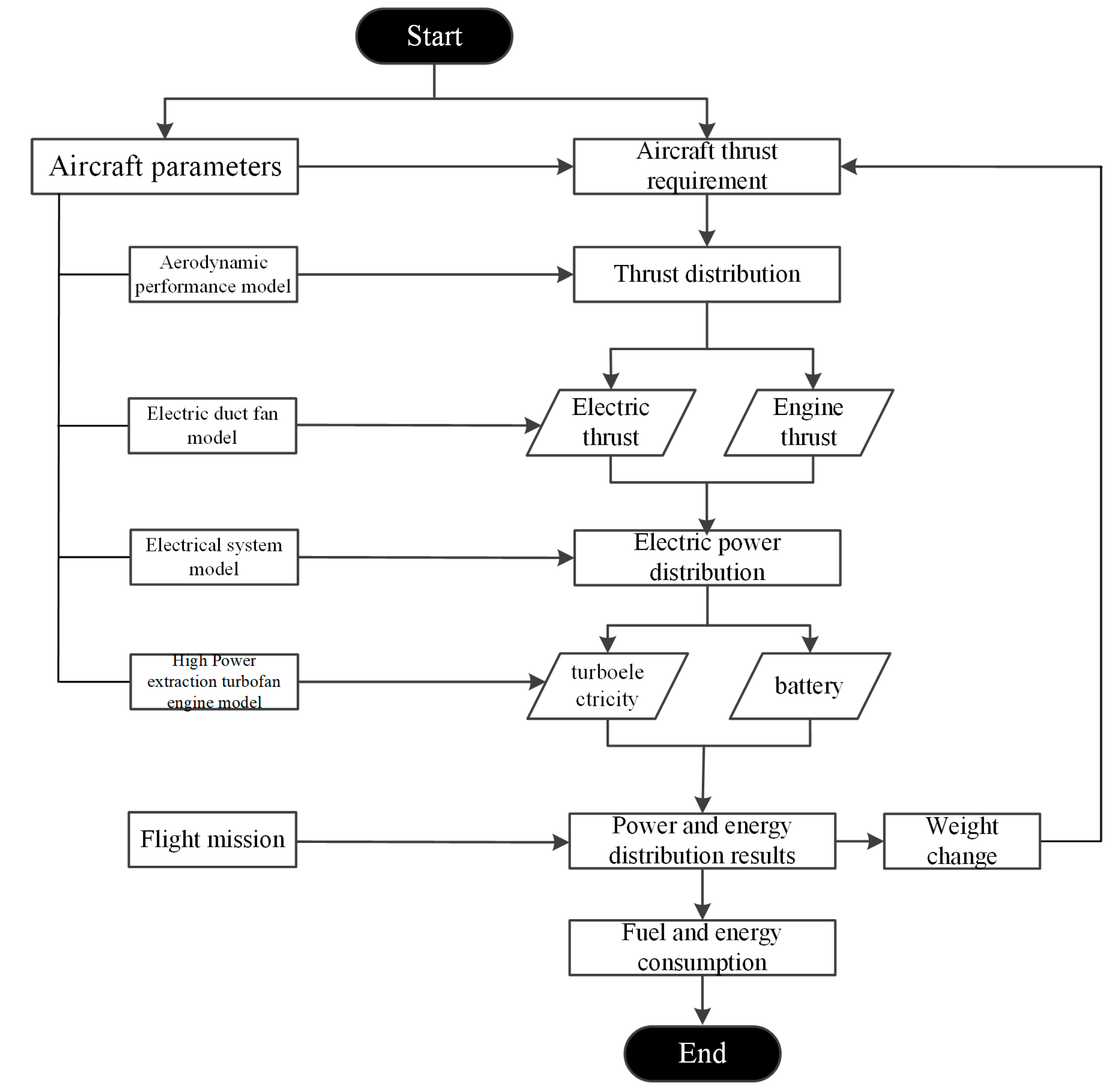
The energy flow model follows the forward design process of civil aircraft. Based on the aircraft-level requirements, the hybrid electric aircraft scheme was analyzed and evaluated, and the thrust and power distribution were carried out according to the mission profile, and the main parameters of the electric propulsion system were determined. The overall performance calculation model of the aircraft is iterated to calculate the fuel and energy consumption of the aircraft under the flight profile, and the performance calculation results are obtained, including range, maximum take-off weight, fuel, and energy consumption, etc., which are used as the core indicators to evaluate the performance and revenue of hybrid electric aircraft.
Input parameters of the energy flow model are shown below.
(1)
Main parameters of the aircraft: including maximum take-off weight, range, seat class, maximum take-off speed, lift–drag ratio, etc.
(2)
Flight profile: including flight status, altitude, speed, range, etc.
(3)
Engine parameters: including use status, thrust, fuel consumption, weight, bypass ratio, etc.
(4)
Electric propulsion system parameters: including the power density, energy density and efficiency of motor, battery and power of electrical system, as well as the shaft power, pressure ratio, flow rate, and size of electric duct fan.
Energy flow model output parameters are shown below.
(1)
Fuel consumption: fuel consumption.
(2)
Energy consumption: total energy consumption for battery and engine.
(3)
Electric propulsion system parameters: weight decomposition, etc.
(4)
Overall parameters of hybrid electric aircraft: including maximum take-off weight, seat class, range, etc.
The process of energy flow for hybrid electric aircraft is shown in Figure 4. According to the main parameters and thrust requirements of the aircraft, the thrust distribution for engine and electric propulsion are carried out, and the electric power is calculated. Then, the power distribution of the turbine electric and battery is figured out, and the data, such as the weight and efficiency of the electric propulsion system, are calculated according to the electric propulsion parameters, and the data are fed back to the overall aircraft calculation model to evaluate the performance of the hybrid electric aircraft.

2.2. The Energy Path Architecture

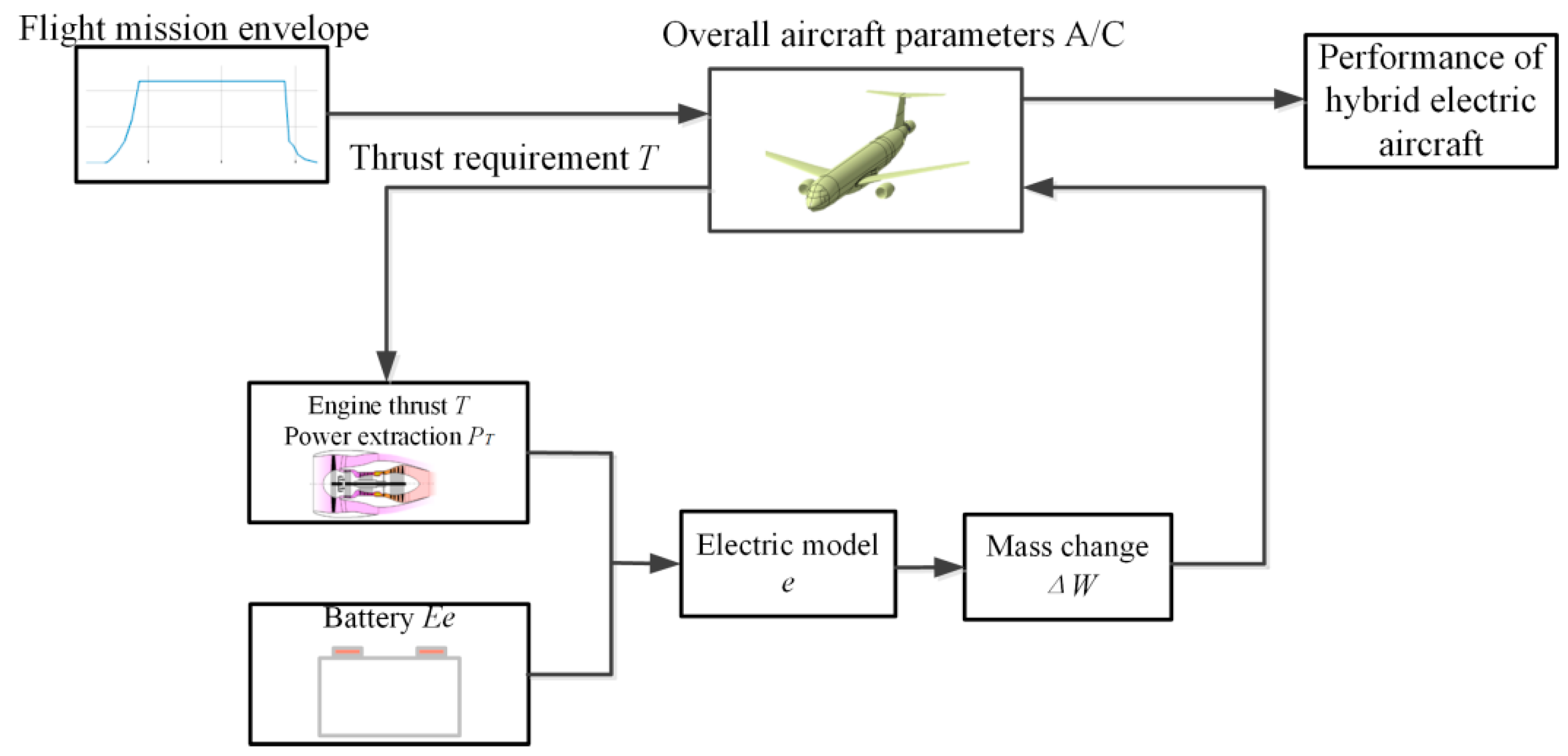
From the perspective of energy transfer paths, under the premise that the mission profile is used as the input, the thrust ratio of the turbofan engine and the duct fan power unit is distributed, and then the energy combination ratio is distributed. Combined with the performance of turbofan engines and electric duct fan propulsion and the performance of the electric power system, the overall parameter of hybrid electric aircraft is carried out. In order to meet the total thrust requirements of the aircraft, the fuel consumption of the power system (or the combined energy consumption required to produce the total thrust) is analyzed to obtain the hybrid power system evaluation results. The Schematic of the hybrid electric aircraft energy flow is shown in Figure 5.
The overall parameters of the baseline aircraft in this paper are shown in Table 1.
Based on the turbine and battery architecture, the fuel and energy consumption of the hybrid electric aircraft in this paper are composed of the following parts.
(1)
Aerodynamic configuration: the use of advanced aerodynamic configuration such as BLI technology to increase propulsion efficiency.
(2)
Turbofan engine: the engine can be designed to work in a high-efficiency area and provide high-power energy extraction.
(3)
Green energy: increase the energy proportion of new energy batteries, reduce fuel consumption, improve energy conversion efficiency, and improve aircraft emission indicators.
(4)
Weight gain: fuel consumption caused by weight gain.

2.3. Energy Flow Models for Key Components

2.3.1. Aerodynamic Characteristics Model

Hybrid electric aircraft use advanced aerodynamic technology based on BLI, such as NASA’s STARC-ABL project and the CENTERLINE project. The basic principle of BLI is that the airflow drawn from the boundary layer to the fan has a lower speed than the free flow, and less energy is needed to achieve the same thrust [22].
Figure 6 shows the comparison of Mach number cloud images of the two configurations. It can be seen from the comparison that the Mach number distribution before the middle of the fuselage of the two configurations is basically the same. The nacelle of the tail electric propulsion system is located in the low-Mach number area at the end of the fuselage, so the intake air of the tail thruster draws the boundary layer of the fuselage and the low-Mach number airflow, which is conducive to improving the propulsion efficiency. The higher exhaust speed of the tail push will fill the fuselage wake, which is also conducive to improving the aerodynamic characteristics. The simulation results in reference [23] and reference [10] are compared to illustrate the confidence of the simulation results in this paper.
From the perspective of energy loss, BLI can reduce the energy loss of the engine jet, and the power consumption is less than that of a conventional engine under the same thrust. Therefore, the power required per unit of thrust is small; that is, the propulsion efficiency is improved.
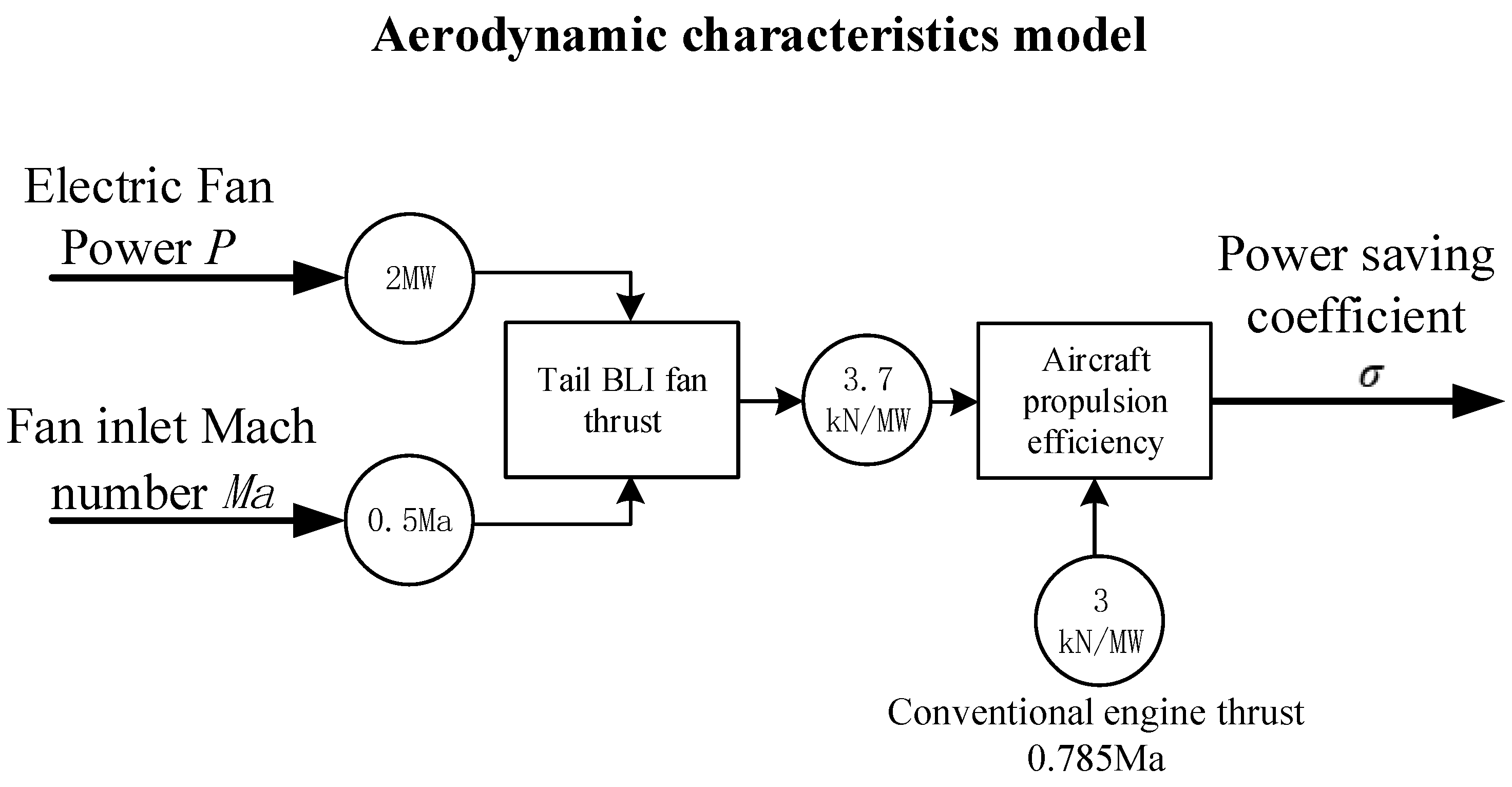
For the aircraft BLI aerodynamic characteristics, the input of the model is fan power and the fan inlet Mach number, and the output parameter is the power saving coefficient σ (the power consumption of the BLI electric duct fan per unit thrust compared with the traditional fan saving ratio). The model of the aerodynamic BLI model is shown in Figure 7.
Conventional engine fan power ratio is as follows.
E x t e r n a l   d u c t   f a n   t h r u s t E x t e r n a l   d u c t   f a n   s h a f t   p o w e r T P 1
BLI electric duct fan push power ratio is as follows.
E l e c t r i c   f a n   t h r u s t E l e c t r i c   f a n   P o w e r = T P 2
The electric duct fan power device inhales the low-Mach number airflow in the fuselage boundary layer, which is conducive to improving the thrust per unit shaft power, so TP2 > TP1. Assuming that the shaft power of the propulsion motor is Pmotor, the power saving coefficient is defined as follows.
σ = T P 2 T P 1 T P 1
According to the research of BLI technology, using the BLI electric duct fan can increase the thrust per unit power by more than 20–25% compared with a traditional engine (external duct fan). The overall aircraft propulsion efficiency is expected to increase by 3% to 5%. The influence of BLI on propulsion efficiency under different powers is analyzed, as shown in Figure 8.

2.3.2. High-Power Extraction Turbofan Engine Model

The turbofan engine used in the hybrid electric aircraft provides thrust for the aircraft on the one hand, and high-power shaft power extraction on the other hand to provide electric energy. It is necessary to carry out overall engine performance analysis to evaluate the impact of high-power electrical power extraction on overall engine performance, especially on unit fuel consumption (SFC) and other indicators.
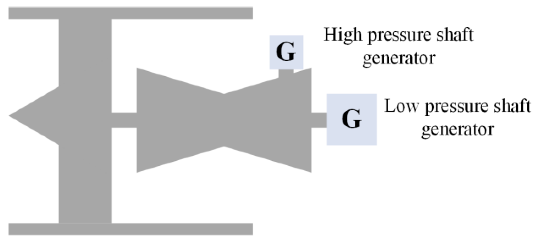
For high-power electrical power extraction, shaft power extraction can be considered from the engine high-pressure shaft or low-pressure shaft, as shown in Figure 9. Based on the analysis of high and low shaft power extraction, for future turbofan engines requiring high-power extraction, if short-term high-power extraction is required, extracting power from a low-pressure shaft is more conducive to the stable operation of the engine, while extracting power from a high-pressure shaft is suitable for the engine to provide a stable low-power output.
For the high-power extraction turbofan engine module, the input of the model is the aircraft thrust demand and the turbine–electric shaft power extraction demand, and the output is the engine fuel consumption Mp. The turbofan engine model is shown in Figure 10.
The parameters of the high-power extraction turbofan engine are shown in Table 2.
When the generator extracts the electric power from the engine, the fuel compensation calculation is as follows:
M p = P C K C e g exp ( C e τ 0 g K ) 1
where P represents for shaft power extracted from the engine, kW; K represents the lift-drag ratio of the aircraft; Ce represents fuel consumption per unit thrust, kg(N·h); C represents engine fuel consumption per unit shaft power, kg/(kW·h); g represents acceleration of gravity, m/s2; and τ0 represents the flight time.
The calculation for extract engine fuel consumption per unit shaft power is as follows:
C = 2.94 C p , g T i n , t H u ε c T i n , c   ( π c 0.286 1 )
where Cp,g represents gas specific constant pressure hot melt, J/(kg·K); Hu represents unit calorific value of fuel combustion, J/kg; Tin,c represents compressor inlet temperature, K; Tin,t represents turbine inlet temperature, K; εc is the complete coefficient of fuel combustion; and πc represents compressor total pressure ratio.

2.3.3. Electrical System Model

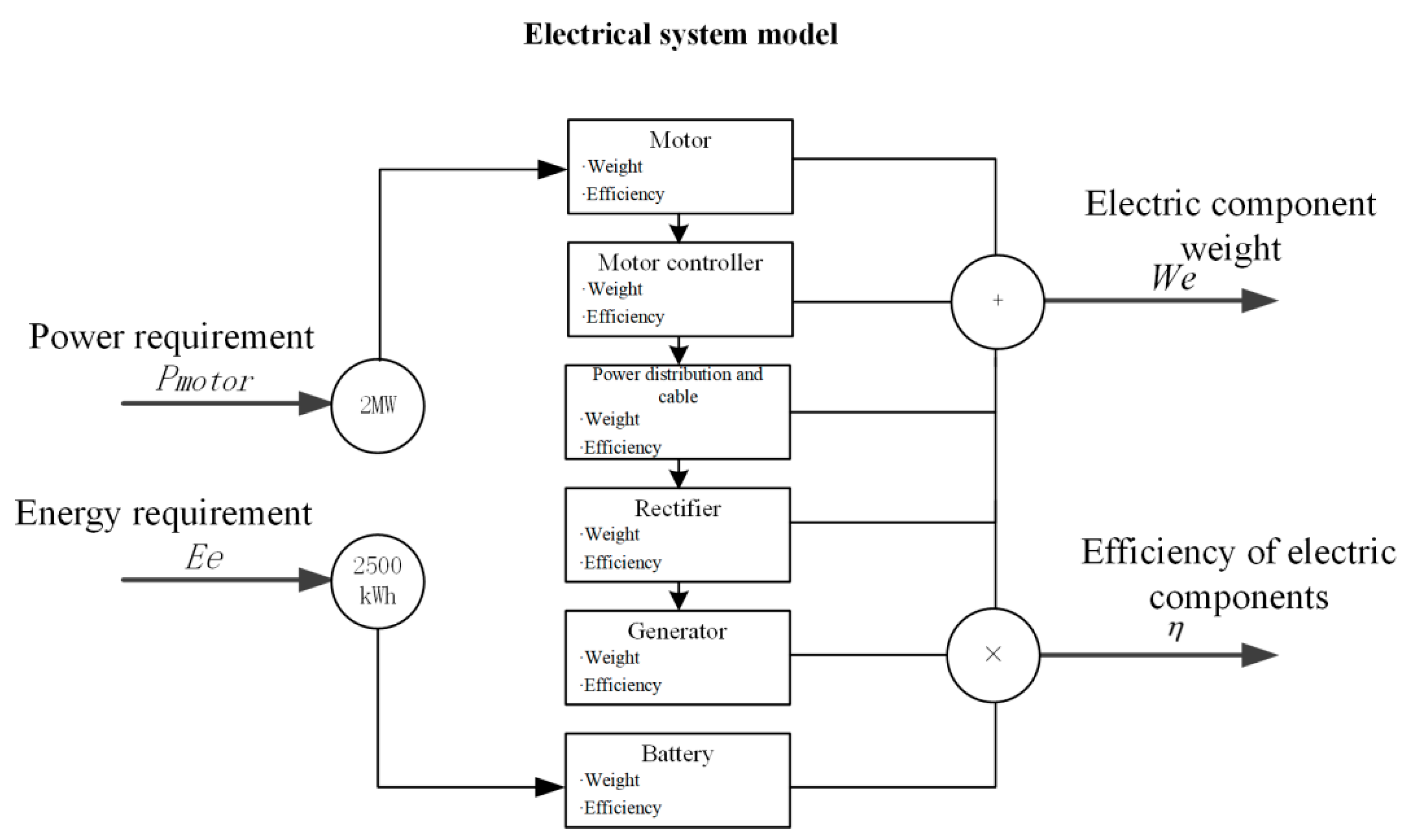
Electrical systems include the generator, rectifier, battery, motor, motor controller, cooling system, etc. The engine drives the generator to produce electric power. Generators, the rectifier, and battery constitute a hybrid power supply system to produce high-voltage direct current to the motor controller and motor. The electric motor converts electric power into mechanical energy and drives the electric duct fan power unit to generate thrust. In order to ensure the function of the high-power electrical system, it is necessary to equip a cooling system to dissipate heat from the electric components.
For the electric model, its input is the power demand of the aircraft’s electric propulsion and the energy demand of the aircraft. The output is the weight of the electrical component and the combined efficiency of the electrical component. The electrical system model is shown in Figure 11.
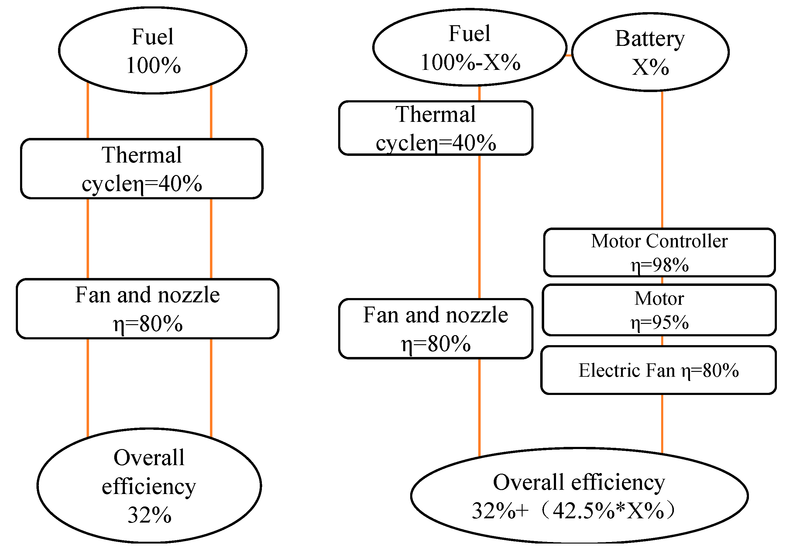
As shown in Figure 12, according to the technical level of traditional gas turbine engines, assuming that the thermal efficiency of the engine is 40% and the propulsion efficiency is 80%, the total efficiency is 32%. Assuming that the electric propulsion system uses the battery as the energy source, the electric energy generated by the battery is transmitted to the electric duct fan, and the total efficiency can reach 74.5%. If the battery ratio is X%, then the total efficiency of the whole machine is 32% + 42.5% * X%. By adjusting the battery ratio, the total energy conversion efficiency of the aircraft can be optimized. If the battery ratio X% is 10%, the total efficiency of the aircraft is 36.25%. The use of battery is more direct in reducing fuel consumption.
It is assumed that the electrical system component parameters of a hybrid electric aircraft are shown in Table 3.
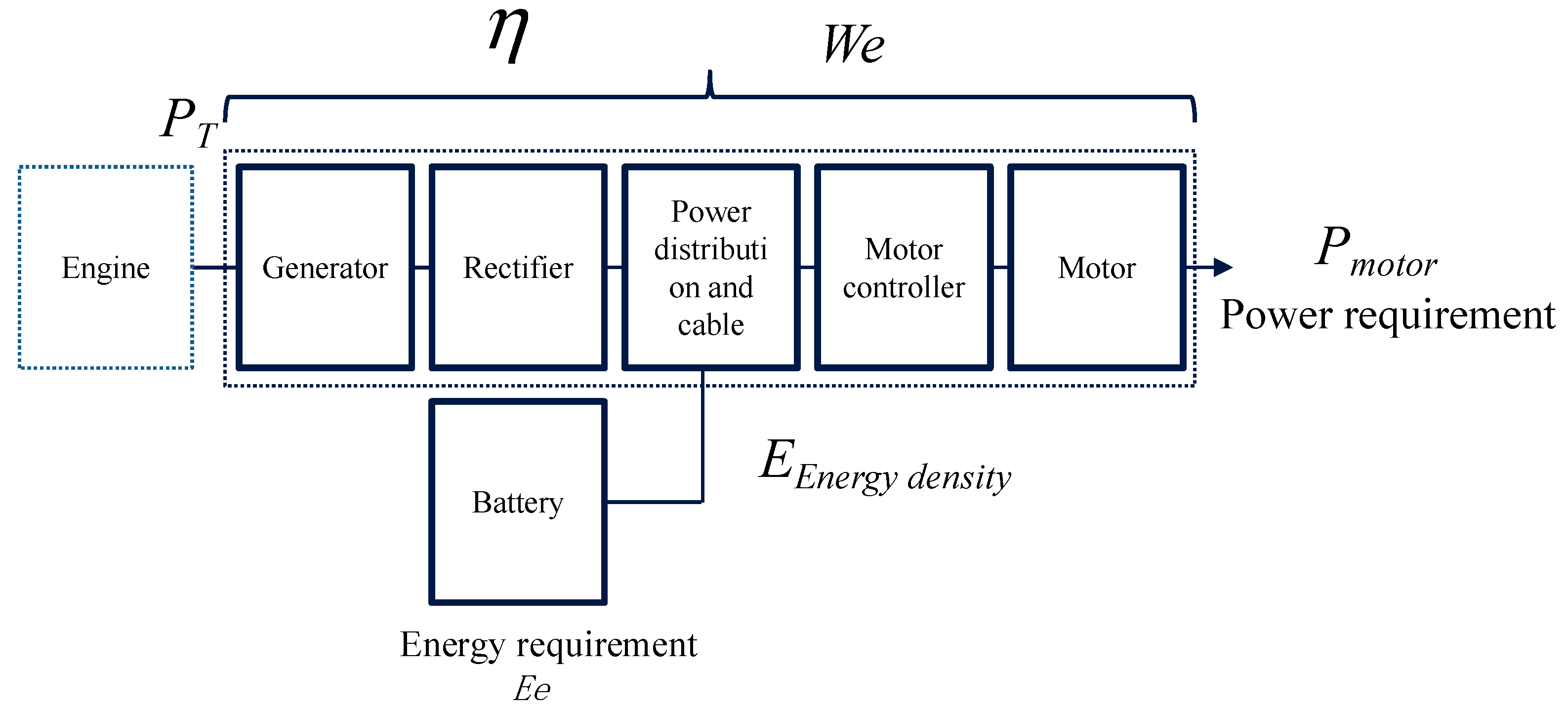
Electrical system components have three main important parameters, as shown in Figure 13.
Electrical system weight: We.
Electrical system Transmission efficiency: η .
Battery energy density: EEnergy density.

2.3.4. Electric Duct Fan Model

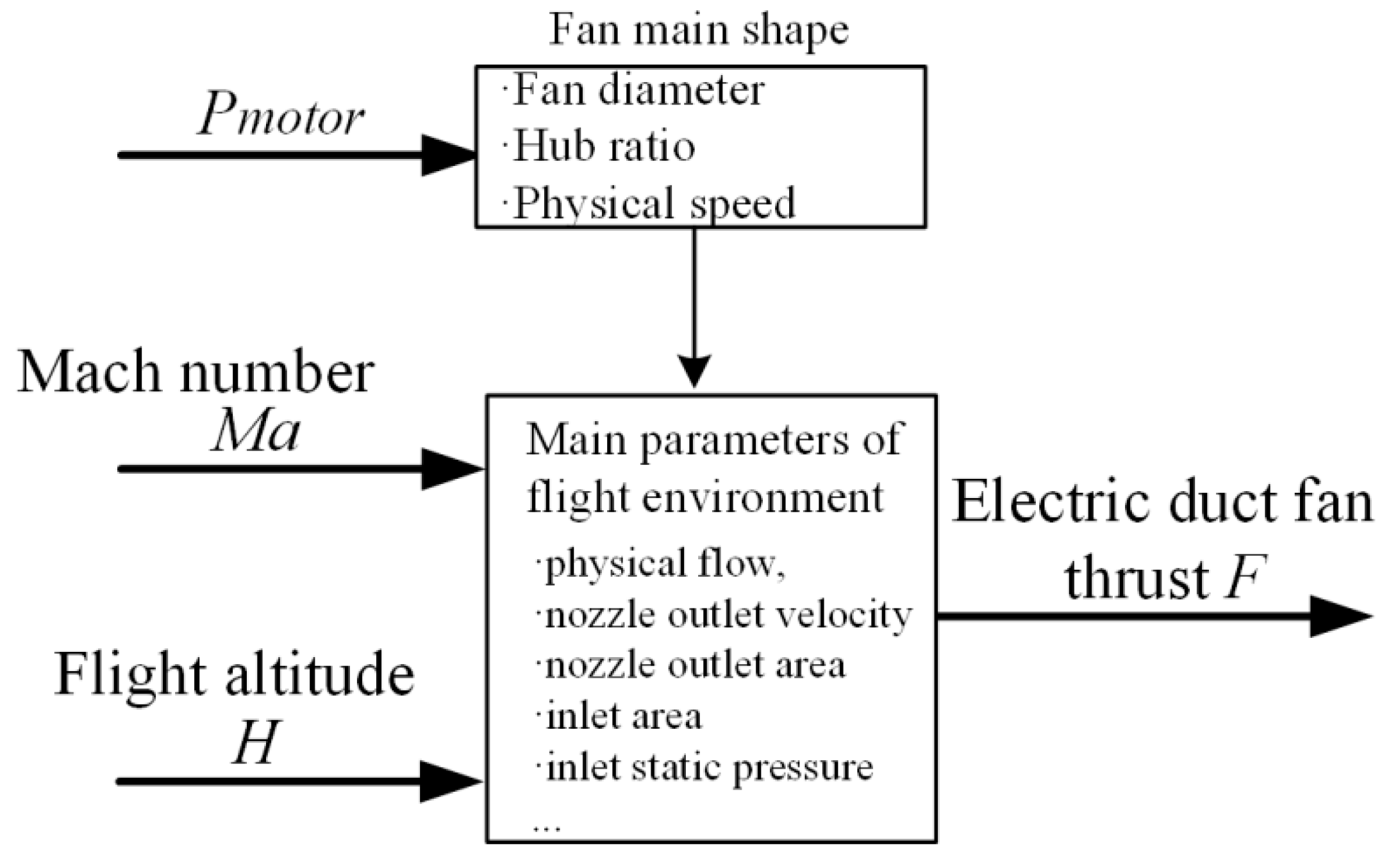
The electric duct fan power device module comprises an inlet, an electric duct fan, an exhaust nozzle, and other parts. The electric duct fan power device transmits electric power into aircraft thrust. For the electric duct fan, the inputs in the aircraft energy flow calculation model are flight altitude, Mach number, and propulsion motor shaft power, etc., and the output is the thrust of the electric duct fan power unit. The model of the electric duct fan component is shown in Figure 14.
The main parameters of the electric duct fan are shown in Table 4.
Based on the restriction of the electric duct fan index, the control body shown in Section 0~3 is selected as the calculation domain to calculate the thrust of the electric duct fan power unit.
In Figure 15, “0”, “1”, “2”, and “3”, respectively, represent the physical parameters of the above section locations. “0” is inlet–inlet; Section “1” is inlet–outlet, electric duct fan inlet; “2” is electric duct fan outlet, exhaust nozzle inlet; “3” is exhaust nozzle outlet.
For the control body shown in Figure 15, the thrust of the electric duct fan power unit is as follows:
F = W v 3 v 0 / 1000 + A 5 p 3 p a j A 0 p 0 p a j
where F is the thrust of the electric duct fan power unit, kN; W is the electric duct fan power unit’s physical flow, kg/s; v3 is the exhaust nozzle outlet velocity, m/s; v0 is the inlet–inlet speed, m/s; A3 is the exhaust nozzle outlet area, m2; A0 is the inlet area, m2; p3 is the exhaust nozzle outlet static pressure, kPa; p0 is the inlet–inlet static pressure, kPa; and Pair is ambient static pressure at the current altitude, kPa.

2.4. Flight Mission Analysis

2.4.1. Weight for Fuel Consumption

Assuming that the weight gain of the hybrid electrical system is ΔW in a given flight time τ0, the calculation model of fuel consumption caused by transporting this weight is as follows:
M f = Δ W exp ( C e τ 0 g K ) 1
where g represents the acceleration of gravity, m/s2; K represents the lift–drag ratio; Ce represents units of fuel consumption, kg/(N·h); and τ0 represents flight time.

2.4.2. Fuel Consumption

In each flight stage, such as taxi, take-off, climb, cruise, descent, approach, slide, etc., the fuel consumption Mb of the engine during the whole flight stage can be calculated according to the thrust of the aircraft mission profile and the unit of fuel consumption rate of the engine.
M b = G i = 1 G i = i T G i C e G i τ G i
where TGi represents thrust during the flight phase, CeGi represents unit of fuel consumption, kg/(N·h); τGi represents flight time; and Gi represents different flight phases.
The fuel consumption of hybrid electric aircrafts is the sum of the fuel consumption caused by thrust, fuel consumption caused by the increase in weight brought by electric propulsion, and fuel consumption caused by the extraction of the high shaft power of the engine. The total fuel consumption is as follows.
M = M b + M f + M p

2.4.3. Energy Consumption

Energy consumption is defined as the energy consumed by the entire aircraft. The energy consumption calculation is as follows:
E = M J C + E e
where JC represents the fuel heat value kWh/kg; Ee represents the battery capacity kWh.

3. Model Validation and Compared with the References

3.1. Compared with the References

Both reference [9] and reference [10] adopted the same BLI configuration, and used the energy form of turbo electricity. The benefit of pure turbo electricity configuration aircraft in this paper is analyzed, and the results for fuel gain are compared with reference [9] and reference [10]. The results can also prove that the energy flow analysis method shows a certain theoretical credibility.The gain comparison for turbine–electric hybrid aircraft is shown in Table 5.

3.2. Compared with the Other Professional Software

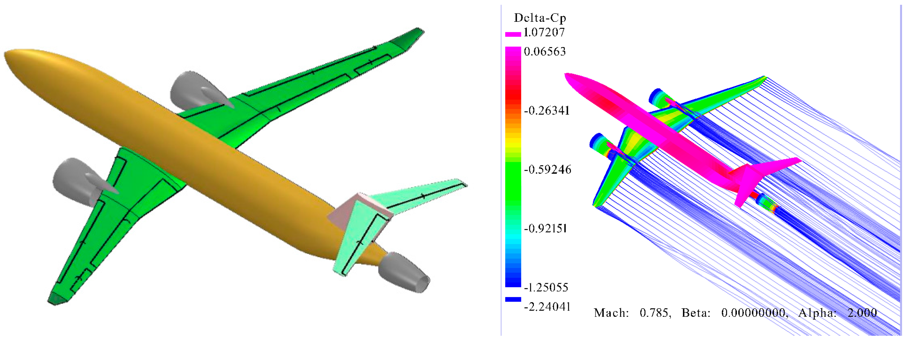
The professional tool is used to analyze the configuration of BLI. Based on OpenVSP 3.40 software, the aircraft aerodynamic characteristics are calculated by using the surface element method. According to the analysis, the propulsion efficiency is increased by about 3% which is shown in Figure 16. It is basically consistent with the calculated results in this paper.
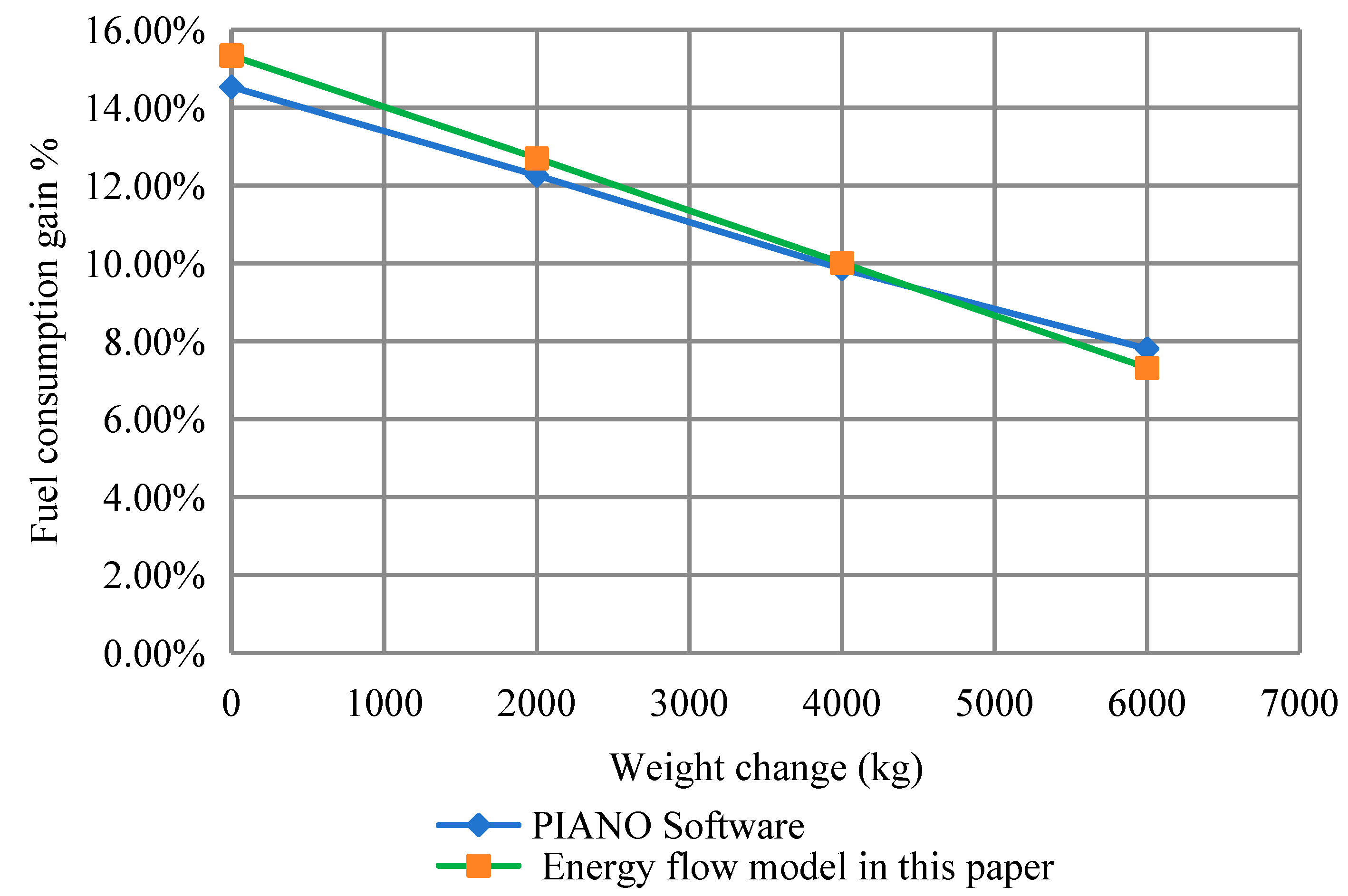
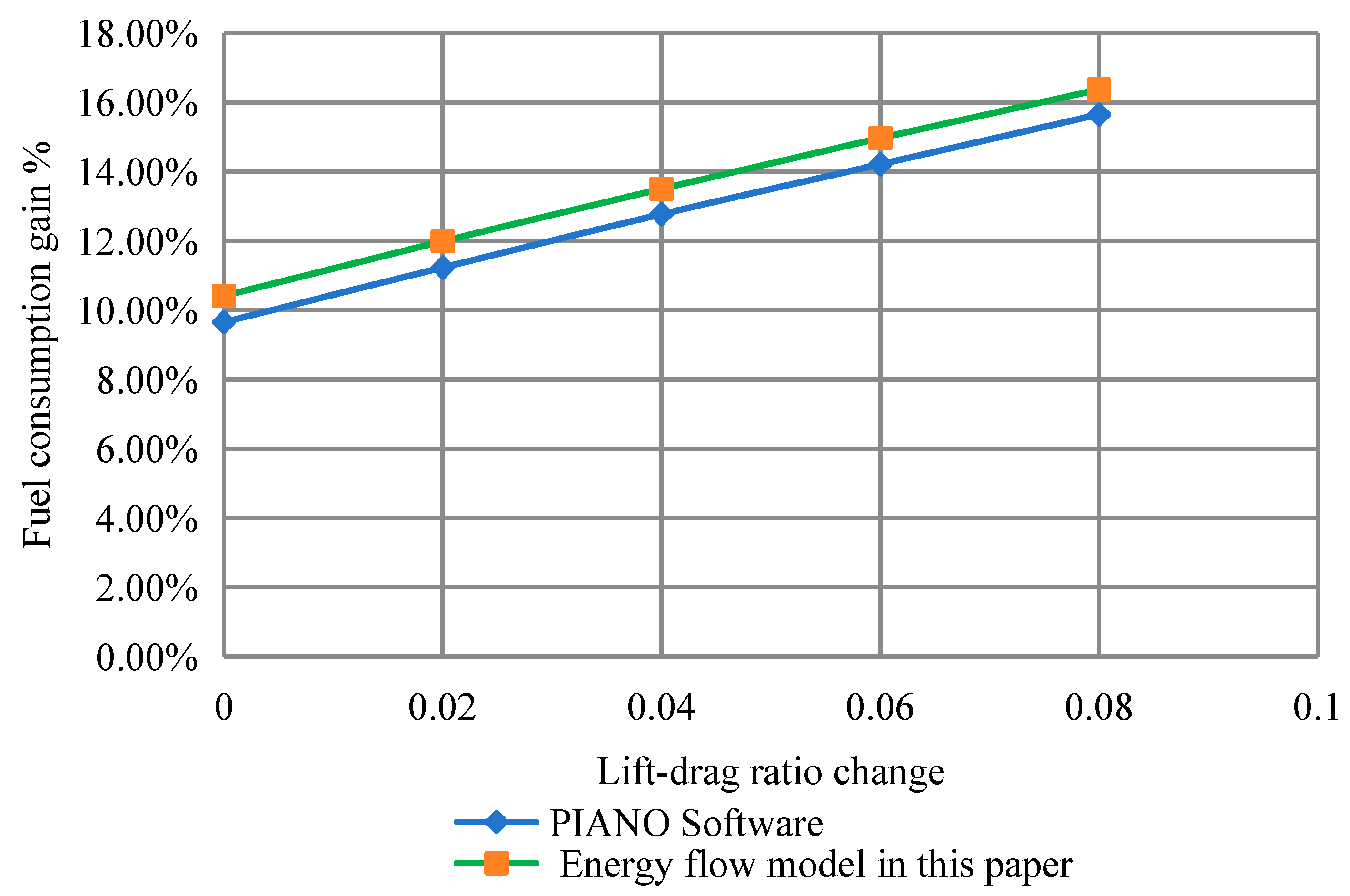
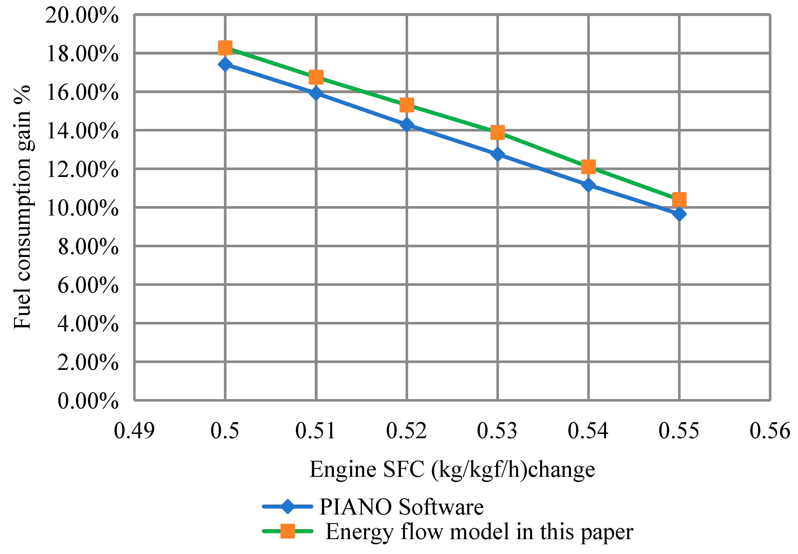
In order to further calibrate the accuracy of the model, the proposed energy flow method is used for comparison with the calculation results of PIANO software. Based on the aircraft parameters in the paper, PIANO software is used to analyze the effects of weight changes, lift–drag ratio changes, and engine SFC changes on aircraft fuel consumption, and the following data and curves can be obtained.
The influence of weight increase on aircraft fuel consumption in the range of 0–6000 kg is analyzed. By comparing with the calculation result from PIANO and the method of this paper, the maximum error obtained is 0.8%, as shown in Figure 17.
The influence of the lift–drag ratio on aircraft fuel consumption in the range of 0–8% is analyzed. Comparing between the calculation method developed by PIANO and the method of this paper, the maximum error obtained is 0.76%, as shown in Figure 18.
The influence of engine SFC on aircraft fuel consumption in the range of 0.5–0.55 (kg/kgf/h) is analyzed. Comparing between the calculation method developed by PIANO and the method of this paper, the maximum error obtained is 1.1%, as shown in Figure 19.
By comparison with PIANO, it can be proved that the analysis method described in this paper has relatively high model accuracy. The calculation model has a fast calculation speed, which is suitable for the rapid iteration and calculation of the overall aircraft scheme. It has the characteristics of flexibility and scalability.

3.3. Limitation and Improvement

In this paper, a theoretical analysis of and calculations for hybrid electric aircraft are performed. The energy flow model is mainly specific to the characteristics of hybrid electric aircraft. It is mainly used to solve the problem that traditional analysis software cannot handle multiple energy types, such as turbine electricity and battery, and improve the speed of computing and scheme iteration. The calculation method is validated by comparison with reference literature and professional calculation software. The three key indicators, weight changes, lift–drag ratio changes, and engine SFC changes, were mainly selected. Although there are some deviations, the model still shows high precision. Therefore, the energy flow model in this study is feasible.
Based on the energy flow model, the architecture and parameters of the aircraft energy system can be optimized from the aircraft level. The energy flow analysis method mentioned in this paper is based on a function model which is limited by aircraft conceptual design. Furthermore, System tests can be carried out for hybrid electric propulsion system verification in the future.

4. Results and Discussion

4.1. Analysis of Power Distribution

4.1.1. Analysis of Turbine Electricity

Firstly, regarding the power of a hybrid electric aircraft without a battery, only the impacts of BLI and turbine electricity are evaluated. The turbine–electric architecture is shown in Figure 20.
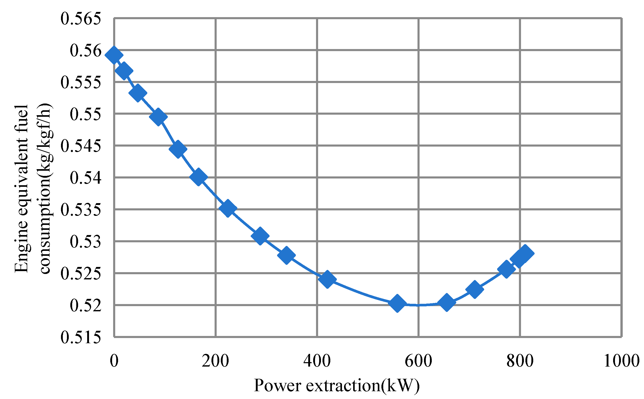
The equivalent fuel consumption of the engine can be defined as follows:
S F C e q = M τ 0 T
Under cruising conditions, the equivalent fuel consumption is the lowest when the high-pressure shaft of a single generator is extracted at 600 kW, as shown in Figure 21.

4.1.2. Analysis of Different Battery Mixing Ratios

Secondly, the different mixing ratios of turbine–electric and lithium batteries were analyzed for comparison with the baseline configuration.
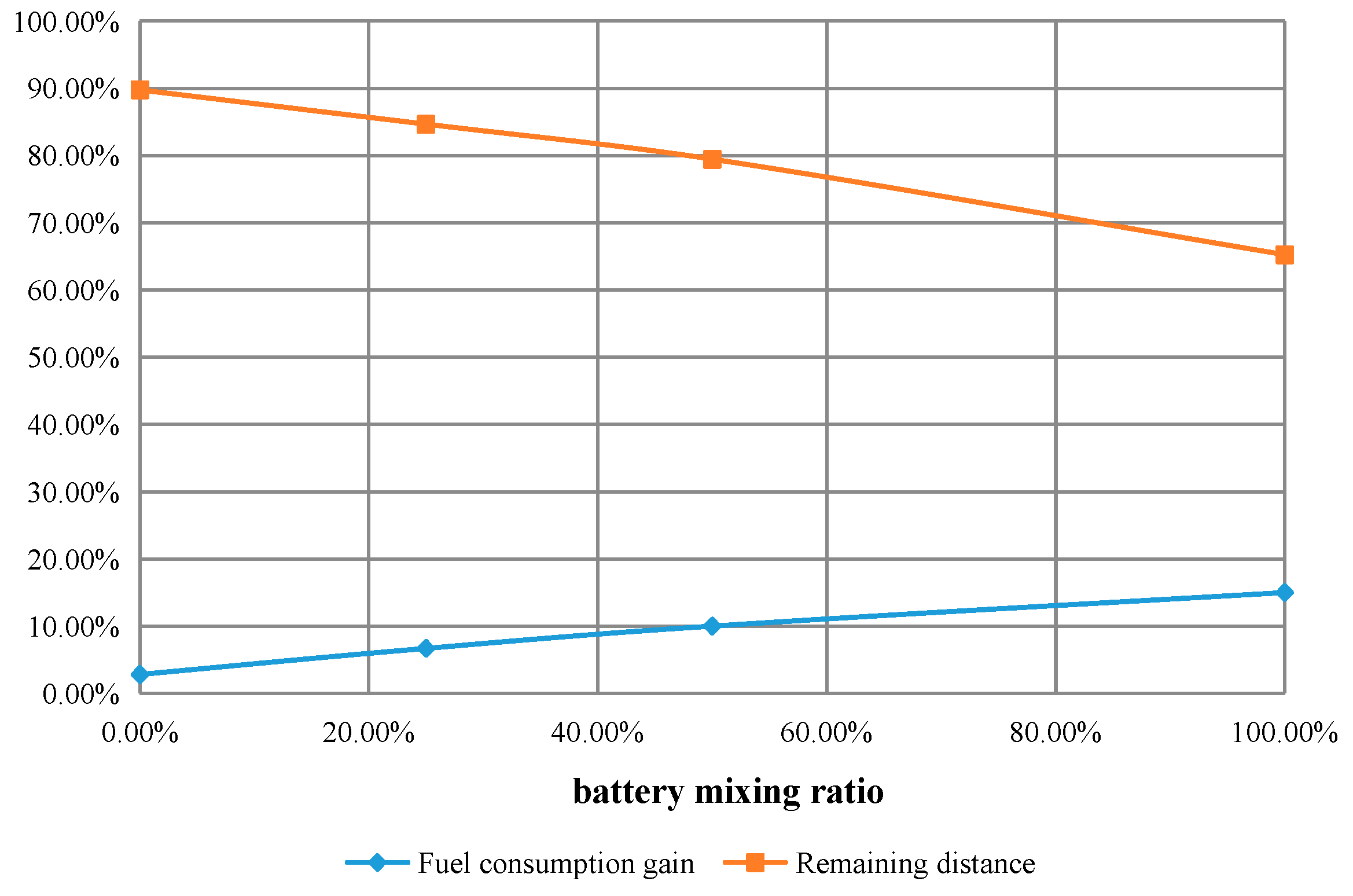
Taking the 2 MW electric propulsion system as an example, the mixing ratio of different turbine–electric and lithium batteries was analyzed. The ratio of lithium battery power to 2 MW was defined as the battery mixing ratio, and the influence of different battery mixing ratios on fuel consumption gain and weight cost were analyzed, as shown in Figure 22. From the figure, it can be found that the higher the battery ratio, the greater the fuel benefit, but also the greater the reduction in range, which affects the range of the aircraft. To meet range and fuel revenue targets, a combination of turbo and battery is required. The battery reduces fuel consumption significantly, but the weight limit and the maximum range target need to be considered.
From the analysis results, two engines using 600 kW turbine electricity, plus a 1 MW lithium battery composed of a 2 MW hybrid power system is suitable. This ensures a higher fuel gain with less reduction in range.
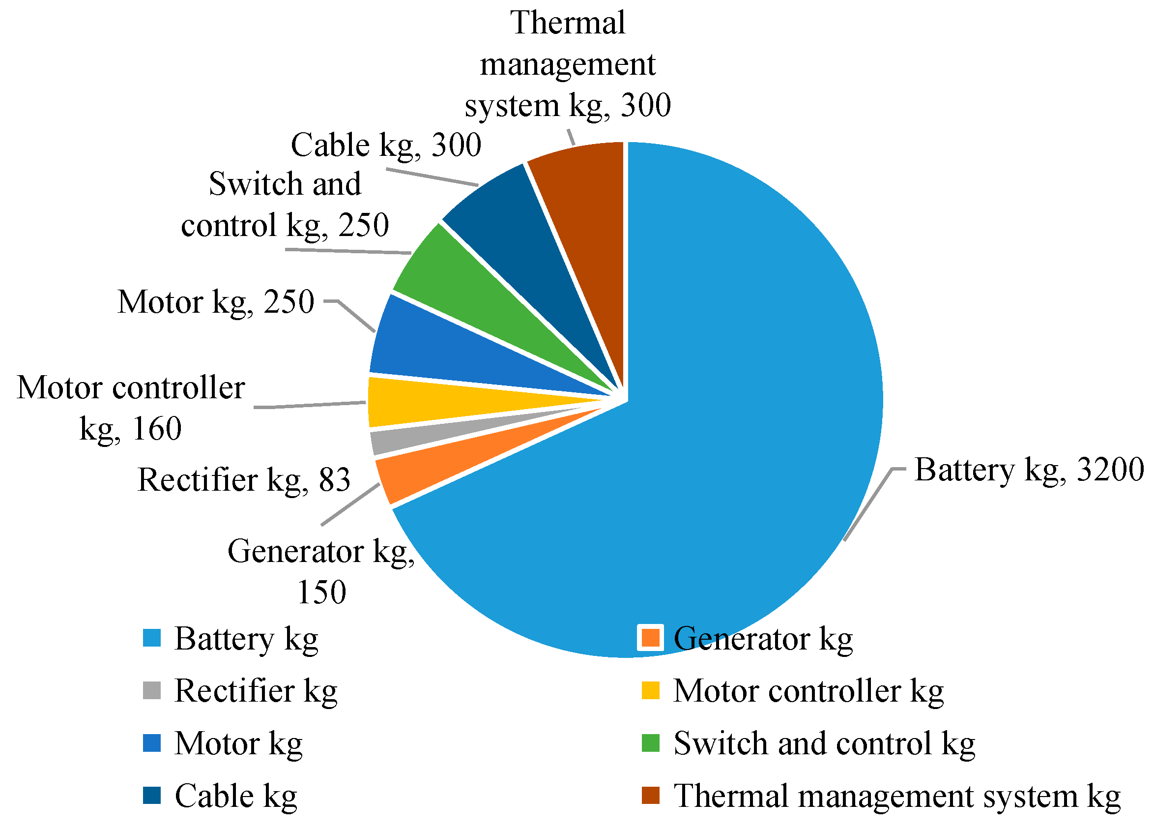
According to the hybrid power architecture and the electrical components in Table 3, the weight of the electric components is calculated. The weight statistics are shown in Figure 23, totaling about 4693 kg.

4.2. Analysis of 800 Nautical Miles

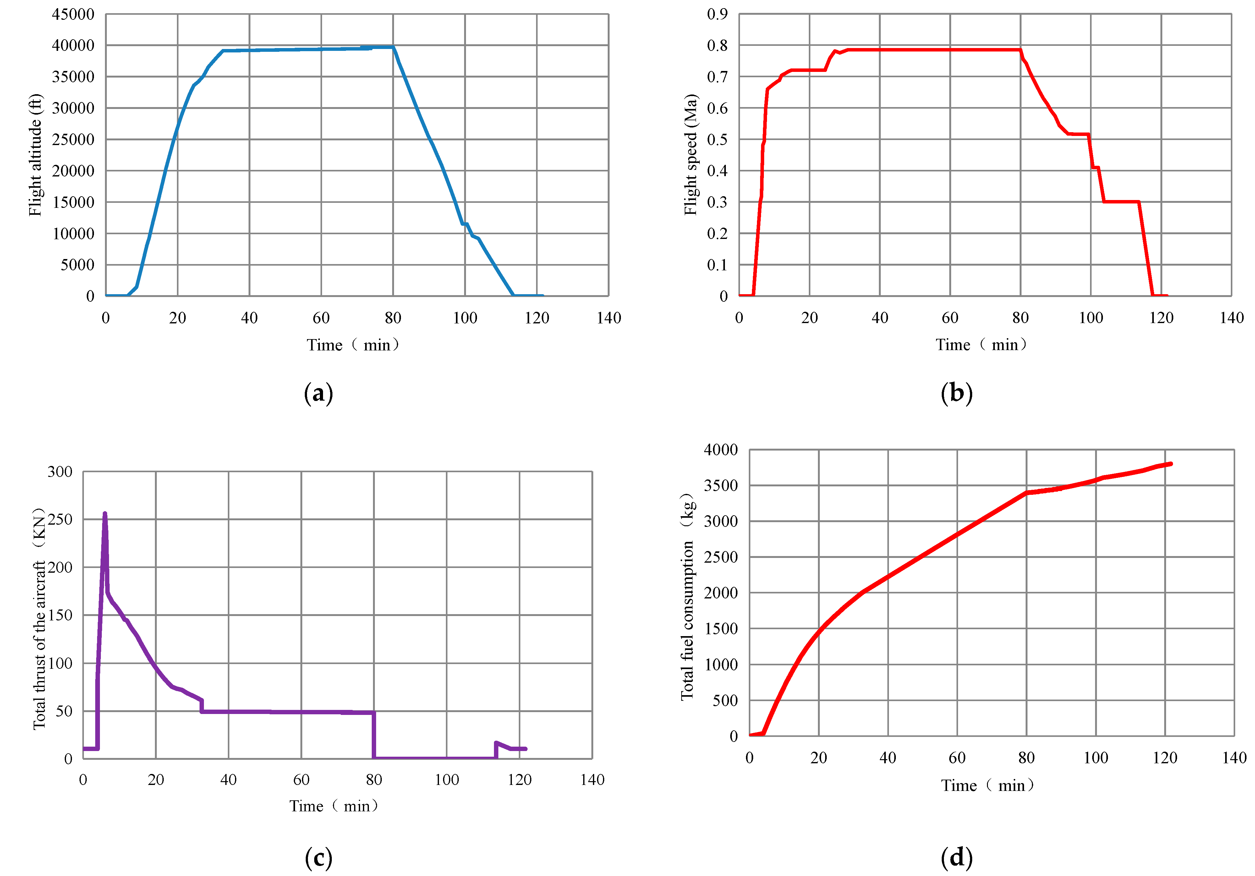
At 800 nautical miles, the flight altitude, flight Mach number, thrust, and fuel consumption of the hybrid electric aircraft were analyzed, as shown in Figure 24.
In a typical 800 nautical mile segment, the hybrid electric aircraft is expected to consume close to 4 tons of fuel and 2500 kWh of electricity, which is expected to reduce wheel fuel consumption by 10% and energy consumption by 4.7% compared to the baseline aircraft.
In the typical flight segment of 800 nautical miles, the effects of different battery energy densities on fuel and energy consumption were analyzed, as shown in Figure 25. Based on the architecture form of energy flow for hybrid electric aircraft in this paper, the energy density of batteries needs to be above 400 Wh/kg to achieve fuel and energy consumption benefits for large hybrid electric aircraft.
In the 800 nautical mile flight segment, the turbine–electric transmission efficiency (from the generator to the output shaft of the propulsion motor) has an impact on fuel and energy consumption income. As shown in Figure 26, the turbine–electric transmission efficiency of hybrid electric aircraft requires more than 85–90% to obtain high fuel and energy consumption benefits.

4.3. Analysis of Different Ranges

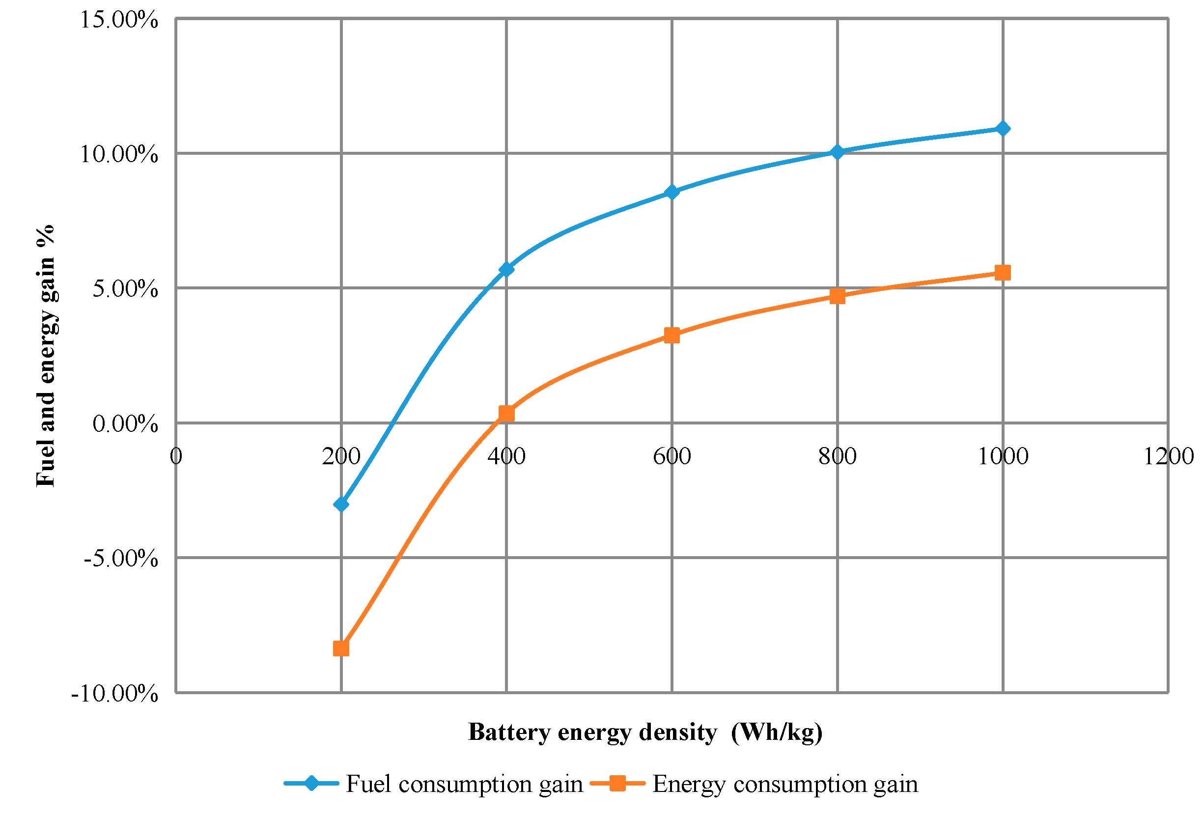
The fuel and energy benefits are analyzed for different ranges, as shown in Figure 27. Limited by the power density of the electric component system and the energy density of the battery, the fuel and energy consumption benefits will decrease with the increase in the range, so it seems that hybrid electric aircraft is more suitable for short-range flights. According to the analysis results in this paper, a range within 2000 nautical miles has fuel benefits, and within 1500 nautical miles has an energy consumption benefit.

4.4. Analysis of the Payload Range

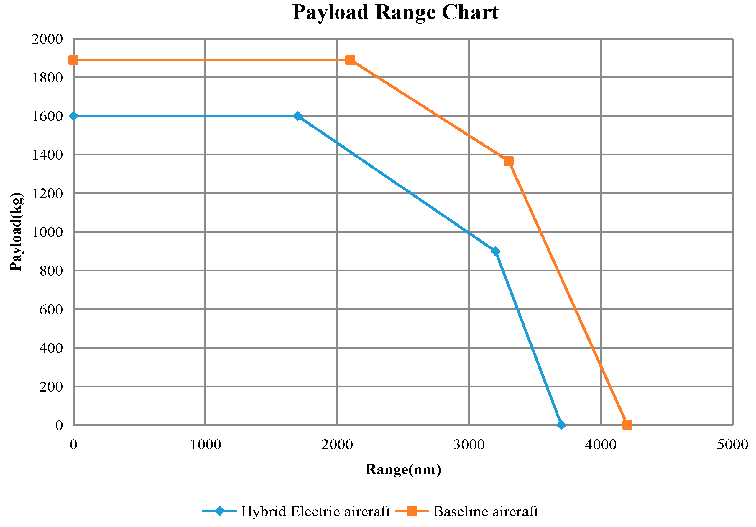
The payload range is a chart that focuses on the impact of aircraft weight, aerodynamics, and engine performance. It can be clearly compared the range of the baseline aircraft and the hybrid aircraft for a given payload, and the corresponding payload for a given range. The comparison between the aircraft payload range chart of the hybrid aircraft demonstrated in this paper and the baseline aircraft is shown in Figure 28.
As can be seen from the payload range Figure 28, although the hybrid electric aircraft has advantages in fuel consumption and energy consumption, the increase in weight of the electric propulsion system will reduce the range and payload, which will affect the overall revenue of the aircraft. Hybrid electric aircraft are more suitable for short-haul transport.

5. Conclusions

An evaluation for hybrid electric aircraft was performed. The architecture and calculation process was defined. Taking single-aisle narrow-body aircraft as the baseline aircraft, models for aerodynamic characteristics, high-power extraction turbofan engines, electrical systems, and electric duct fans were constructed. The results for fuel and energy consumption were given based on mission analysis.
Compared with traditional aircraft, the hybrid electric aircraft’s fuel consumption can reach a reduction of 10%, and energy consumption reduction can reach 4.7% under a typical 800 nautical mile flight segment with a 2 MW hybrid electric propulsion system. The power system distribution was analyzed, and the weight was broken down. The fuel and energy consumption analysis for different flight segments was completed, and the influence of different parameters, such as battery energy density, transmission efficiency, and range, were evaluated. Through the analysis results, it was found that the hybrid electric aircraft are more suitable for short flights. The comparison of the payload range between the hybrid electric aircraft and the baseline aircraft is given.
The energy flow analysis model can be used to analyze the overall parameters of hybrid electric aircraft and can carry out different architecture and parameter analyses in the conceptual design stage, and provide support for functional and performance simulation and verification. In the future, wind tunnel tests and integrated verification of the MW class electric propulsion system will be carried out to support the demonstration results.

Author Contributions

Conceptualization, Y.H.; Formal analysis, H.L.; Validation, J.C.; Supervision, Y.K. All authors have read and agreed to the published version of the manuscript.

Funding

This research received no external funding.

Data Availability Statement

The original contributions presented in the study are included in the article, further inquiries can be directed to the corresponding author.

Conflicts of Interest

Authors Yannian Hui, Hongliang Li, Yuanli Kang were employed by the COMAC Beijing Aircraft Technology Research Institute. The remaining authors declare that the research was conducted in the absence of any commercial or financial relationships that could be construed as a potential conflict of interest.

Abbreviations

GGenerator
M Motor
BLIBoundary layer ingesting
A/CAircraft
eElectric model
ΔWMass change
PElectric Fan Power
MaMach number
δPower-saving coefficient
TAircraft thrust requirement
PTTurbine–electric power extraction
MpEngine fuel consumption
PePower requirement
EeEnergy requirement
WeElectrical component weight
ηEfficiency of electrical component
XBattery ratio
PmotorMotor shaft power
HFlight altitude
FElectric duct fan thrust

References

  1. IATA. Aircraft Technology Roadmap to 2050; International Air Transport Association: Geneva, Switzerland, 2019. [Google Scholar]
  2. ICAO. Environmental Protection, Volume III CO2 Certification Requirement; ICAO: Montreal, QC, Canada, 2017. [Google Scholar]
  3. Xie, Y.; Savvarisal, A.; Tsourdos, A.; Zhang, D.; Gu, L. Review of hybrid electric powered aircraft, its conceptual design and energy management methodologies. Chin. J. Aeronaut. 2020, 34, 432–450. [Google Scholar] [CrossRef]
  4. Finger, D.F.; Braun, C.; Bil, C. Comparative Assessment of Parallel-Hybrid-Electric Propulsion Systems for Four Different Aircraft. J. Aircr. 2020, 57, 843–853. [Google Scholar] [CrossRef]
  5. Bowman, C.L.; Marien, T.V.; Felder, J.L. Turboand hybrid-electrified aircraft propulsion for commercial transport. In Proceedings of the 2018 AIAA/IEEE Electric Aircraft Technologies Symposium, Cincinnati, OH, USA, 9–11 July 2018; pp. 1–8. [Google Scholar]
  6. Felder, J.L. NASA Electric Propulsion System Studies. 2015. Available online: https://ntrs.nasa.gov/api/citations/20160009274/downloads/20160009274.pdf (accessed on 16 July 2024).
  7. Felder, J.L.; Kim, H.D.; Brown, G.V. Turboelectric distributed propulsion engine cycle analysis for hybrid-wing-body aircraft. In Proceedings of the 47th AIAA Aerospace Sciences Meeting Including the New Horizons Forum and Aerospace Exposition, Orlando, FL, USA, 5–8 January 2009. [Google Scholar]
  8. Welstead, J.; Felder, J.L.; Guynn, M.; Haller, B.; Tong, M.; Jones, S.; Ordaz, I.; Quinlan, J.; Mason, B. Overview of the NASA STARC-ABL (Rev. B) Advanced Concept. 2017. Available online: https://ntrs.nasa.gov/api/citations/20170005612/downloads/20170005612.pdf (accessed on 16 July 2024).
  9. Seitz, A.; Habermann, A.L.; Peter, F.; Troeltsch, F.; Castillo Pardo, A.; Della Corte, B.; Van Sluis, M.; Goraj, Z.; Kowalski, M.; Zhao, X.; et al. Proof of concept study for fuselage boundary layer ingesting propulsion. Aerospace 2021, 8, 16. [Google Scholar] [CrossRef]
  10. Samuelsson, S.; Grönstedt, T. Performance analysis of turbo-electric propulsion system with fuselage boundary layer ingestion. Aerosp. Sci. Technol. 2021, 109, 106412. [Google Scholar] [CrossRef]
  11. Moirou, N.G.; Sanders, D.S.; Laskaridis, P. Advancements and prospects of boundary layer ingestion propulsion concepts. Prog. Aerosp. Sci. 2023, 138, 100897. [Google Scholar] [CrossRef]
  12. AIR1168/8A; Aircraft Fuel Weight Penalty Due to Air Conditioning. SAE International: Warrendale, PA, USA, 2011.
  13. De Vries, R.; Hoogreef, M.F.; Vos, R. Range equation for hybrid-electric aircraft with constant power split. J. Aircr. 2020, 57, 552–557. [Google Scholar] [CrossRef]
  14. Batra, A.; Raute, R.; Camilleri, R. On the Range Equation for Hybrid-Electric Aircraft. Aerospace 2023, 10, 687. [Google Scholar] [CrossRef]
  15. Palaia, G.; Abu Salem, K. Mission Performance Analysis of Hybrid-Electric Regional Aircraft. Aerospace 2023, 10, 246. [Google Scholar] [CrossRef]
  16. Silva, H.L.; Resende, G.J.; Neto, R.M.; Carvalho, A.R.; Gil, A.A.; Cruz, M.A.; Guimarães, T.A. A multidisciplinary design optimization for conceptual design of hybrid-electric aircraft. Struct. Multidiscip. Optim. 2021, 64, 3505–3526. [Google Scholar] [CrossRef]
  17. Doff-Sotta, M.; Cannon, M.; Bacic, M. Predictive energy management for hybrid electric aircraft propulsion systems. IEEE Trans. Control Syst. Technol. 2022, 31, 602–614. [Google Scholar] [CrossRef]
  18. Aigner, B.; Nollmann, M.; Stumpf, E. Design of a Hybrid Electric Propulsion System within a Preliminary Aircraft Design Software Environment; Deutsche Gesellschaft für Luft-und Raumfahrt-Lilienthal-Oberth Ev: Bonn, Germany, 2018. [Google Scholar]
  19. Vankan, W.J.; Lammen, W.F. Parallel hybrid electric propulsion architecture for single aisle aircraft-powertrain investigation. In Proceedings of the 9th EASN International Conference on “Innovation in Aviation & Space”, Athens, Greece, 3–6 September 2019. [Google Scholar]
  20. Pornet, C.; Kaiser, S.; Isikveren, A.T.; Hornung, M. Integrated fuel-battery hybrid for a narrow-body sized transport aircraft. Aircr. Eng. Aerosp. Technol. Int. J. 2014, 86, 568–574. [Google Scholar] [CrossRef]
  21. Marciello, V.; Di Stasio, M.; Ruocco, M.; Trifari, V.; Nicolosi, F.; Meindl, M.; Lemoine, B.; Caliandro, P. Design Exploration for Sustainable Regional Hybrid-Electric Aircraft: A Study Based on Technology Forecasts. Aerospace 2023, 10, 165. [Google Scholar] [CrossRef]
  22. Smith, L.H., Jr. Wake ingestion propulsion benefit. J. Propuls. Power 1993, 9, 74–82. [Google Scholar] [CrossRef]
  23. Fernández, A.M.; Smith, H. Effect of a fuselage boundary layer ingesting propulsor on airframe forces and moments. Aerosp. Sci. Technol. 2020, 100, 105808. [Google Scholar] [CrossRef]
Figure 1. Hybrid electric architecture.
Energies 17 05062 g001
Figure 2. BLI configuration aircraft based on tail propulsion. (a) NASA STARC-ABL; (b) CENTERLINE project.
Energies 17 05062 g002
Figure 3. The energy architecture of the hybrid electric aircraft.
Energies 17 05062 g003
Figure 4. The energy flow process of hybrid electric aircraft.
Energies 17 05062 g004
Figure 5. The architecture of hybrid electric aircraft energy path.
Energies 17 05062 g005
Figure 6. Comparison of Mach number cloud image between the traditional aircraft and the BLI aircraft. (a) Comparison of the fuselage Mach number. (b) Comparison of tail Mach number.
Energies 17 05062 g006aEnergies 17 05062 g006b
Figure 7. The aerodynamic characteristics model.
Energies 17 05062 g007
Figure 8. The influence of BLI on propulsion efficiency under different powers.
Energies 17 05062 g008
Figure 9. High-power extraction turbofan engine.
Energies 17 05062 g009
Figure 10. Turbofan engine model.
Energies 17 05062 g010
Figure 11. Electrical system model.
Energies 17 05062 g011
Figure 12. The combined efficiency of batteries and conventional power.
Energies 17 05062 g012
Figure 13. The electrical system.
Energies 17 05062 g013
Figure 14. Electric duct fan model.
Energies 17 05062 g014
Figure 15. Electric duct fan for BLI aircraft.
Energies 17 05062 g015
Figure 16. OpenVSP propulsion efficiency calculation.
Energies 17 05062 g016
Figure 17. Comparison of effects of weight change (kg).
Energies 17 05062 g017
Figure 18. Comparison of effects of Lift-drag ratio change.
Energies 17 05062 g018
Figure 19. Comparison of effects of engine SFC (kg/kgf/h) change.
Energies 17 05062 g019
Figure 20. Turbine–electric architecture.
Energies 17 05062 g020
Figure 21. Equivalent fuel consumption of engine.
Energies 17 05062 g021
Figure 22. Analysis for different battery mixing ratios.
Energies 17 05062 g022
Figure 23. Electric propulsion system weight decomposition.
Energies 17 05062 g023
Figure 24. Main performance curves of hybrid electric aircraft. (a) Flight altitude; (b) Flight speed; (c) Total thrust of the aircraft; (d) Total fuel consumption.
Energies 17 05062 g024
Figure 25. Fuel and energy consumption at different battery energy densities.
Energies 17 05062 g025
Figure 26. Fuel and energy consumption at different turbine–electric transmission efficiency.
Energies 17 05062 g026
Figure 27. Fuel consumption gain and Energy consumption gain in different ranges.
Energies 17 05062 g027
Figure 28. Comparison of payload range between hybrid electric aircraft and baseline aircraft.
Energies 17 05062 g028
Table 1. Aircraft parameter.
ParameterSymbolValue
Maximum take-off weight (kg)MTOW78,000
Maximum fuel weight (kg)FW18,480
Maximum take-off thrust (kN)T240
Standard payload (kg)PL15,580
Operation empty weight (kg)OEW42,600
Maximum range (nautical miles)MR4200
Cruise lift to drag ratioK17
Table 2. The turbofan key parameters.
ParameterSymbolValue
Electrical power extraction (MW)PT0.66
Turbine inlet temperature (K)Tin,t1800
Gas specific constant pressure hot melt J/(kg·K)Cp,g1129
Unit calorific value of fuel combustion(J/kg)Hu42,600,000
Complete coefficient of fuel combustionεc0.97
Compressor total pressure ratioπc35
Table 3. Electrical components parameters.
ParameterSymbolValue
Battery energy density (Wh/kg)EEnergy density800
Power electronics power density (kW/kg)PEPden12
Generator power density (kW/kg)PGden8
Motor power density (kW/kg)PMOTden8
Cooling system power density (kW/kg)PCSden0.8
Generator efficiency %Geff98%
Rectifier efficiency %RECeff98.5%
Motor efficiency %MOTeff96%
Motor controller efficiency %MCeff98.5%
Power distribution and Cable efficiency %PDACeff99%
Table 4. Main parameters of the electric duct fan.
ParameterSymbolValue
Input shaft power (kW)Pmotor2000
Physical speed (RPM)SPrpm4000
Hub ratioHr0.35
Fan diameter (m)FanD1.5
Table 5. The gain comparison for turbine–electric hybrid aircraft.
Comparison ModelFuel Consumption Gain
The aircraft in this paper 2.8%
The aircraft in Reference [9]3.2%
The aircraft in Reference [10]3%
Disclaimer/Publisher’s Note: The statements, opinions and data contained in all publications are solely those of the individual author(s) and contributor(s) and not of MDPI and/or the editor(s). MDPI and/or the editor(s) disclaim responsibility for any injury to people or property resulting from any ideas, methods, instructions or products referred to in the content.