Article

Investigating Enhanced Convection Heat Transfer in 3D Micro-Ribbed Tubes Using Inverse Problem Techniques

1
School of Energy and Building Environment, Guilin University of Aerospace Technology, Guilin 541004, China
2
State Key Laboratory for Modification of Chemical Fibers and Polymer Materials, College of Materials Science and Engineering, Donghua University, Shanghai 200051, China
*
Authors to whom correspondence should be addressed.
Energies 2024, 17(20), 5102; https://doi.org/10.3390/en17205102
Submission received: 29 July 2024 / Revised: 7 October 2024 / Accepted: 11 October 2024 / Published: 14 October 2024
(This article belongs to the Section J: Thermal Management)

Abstract

:
The improved heat dissipation observed in 3D micro-ribbed tubes is primarily influenced by the intricate interplay of multiple structural parameters. Nevertheless, research into the coupling mechanisms of these multi-structural parameters remains constrained by the absence of effective methodology in numerical solutions. In the present work, a new 3D micro-rib structure based on discrete adjoint method is established. Firstly, the research examines the interplay of different parameters (such as arrangement, relative roughness height, angle of attack, and circumferential rows) on the thermo-hydraulic performance. It is noted that the heat transfer efficiency is notably impacted by the relative roughness height. And the arrangement methodology dictates the optimal positioning for heat transfer efficiency. An increase in the number of circumferential rows enhances fluid mixing, while the angle of attack plays a crucial role in the formation of longitudinal vortices. Secondly, the coupling optimization technique is employed to obtain the optimal structure featuring non-uniform relative roughness height by the developed numerical solution. Overall, in comparison to the smooth tube, the optimized ribbed tube exhibits a remarkable 64.9% enhancement in performance evaluation criteria. Finally, a notable enhancement of 10.65–22.78% is observed when comparing with the prevailing micro-rib structures.

1. Introduction

The heat transfer process taking place in the tubes of shell and tube heat exchangers can be categorized as a conventional convection-based heat transfer phenomenon. Current techniques utilized to improve heat transfer efficiency include specific tube geometries (such as flat tubes, elliptic tubes, and spiral tubes) [1], inserts (such as bonded tubes and finned tubes) [2,3], two-dimensional roughness elements (such as continuous ribs or grooves) [4,5], and three-dimensional (3D) micro-ribbed structures (such as threaded tubes [6,7], bug-cell bumps, and pits [8]). Specialized tubes and inserts are integral in enhancing heat transfer by inducing alterations in flow direction and disrupting the boundary layer formed along the tube wall, particularly effective under laminar flow or low Reynolds number conditions. The use of flat and finned tubes expands the heat transfer area, optimizing overall heat transfer performance. However, these modifications lead to an increased pressure drop, ultimately improving heat transfer efficiency at the expense of additional pumping power consumption. Consequently, it is imperative to investigate the heat transfer mechanisms of the newly enhanced heat exchange tube and to further optimize its thermo-hydraulic performance.
The implementation of 3D micro-ribs to induce a longitudinal vortex has been recognized as a key technique for enhancing tube performance in various applications, such as solar water heaters [9,10], shell and tube heat exchangers [11], and oil coolers [12], as evidenced in current academic literature. The heat transfer efficiency of heated tubes is notably affected by the structural characteristics of 3D micro-ribs. Specifically, discrete oblique micro-ribs have shown a 15% increase in overall performance [13], while discrete transverse and curved micro-ribs have demonstrated enhancements exceeding 20% [14,15]. In terms of arrangement mode, staggered arrangement proves to be more effective in enhancing the heat transfer performance of discrete oblique micro-ribs compared to forward arrangement, resulting in an improvement ranging from approximately 27% to 41% [16,17]. The study of micro-ribbed tubes across six different arrangements indicated that the optimal configuration includes symmetrical counterclockwise double-inclined ribs and symmetrical clockwise single-inclined ribs, demonstrating a performance evaluation criterion 1.9% higher than alternative arrangements [18]. In the comprehensive study of arrangement, rib height, and axial angle, it was observed that the heat transfer performance was most effective when micro-ribs had a height of 0.8 and an angle of 40°, while the peak performance evaluation criterion was achieved at a height and angle of 0.1 and 40°, respectively [19]. The heat transfer performance of corrugated micro-ribs surpasses that of conventional structures, demonstrating significant enhancement. Analysis of geometric parameters including ripple number, arrangement mode, and height indicates that micro-rib height plays a crucial role in heat transfer performance [20,21].
Nevertheless, to date, the intricate mechanisms underlying the coupling effects of multiple micro-rib structural parameters remain inadequately understood. Existing literature in this domain typically isolates certain parameters, examining their impact on heat transfer characteristics by varying a single parameter at a time. Consequently, a primary objective of this study is to elucidate the combined influence of multiple rib parameters on the heat transfer performance of heat exchange tubes. More significantly, the direct analysis required to determine the optimal values of multiple parameters typically results in a substantial increase in the computational workload associated with numerical solutions. Therefore, there is a pressing need for effective numerical optimization techniques, which serves as an additional impetus for our current research.
Given the efficiency and cost-effectiveness of multi-structural parameter optimization, the inverse heat transfer problem (IHTP) has demonstrated its efficacy as an optimization method. Consequently, it has been employed in the structural optimization of fuel cells [22], micro-channel radiators [23], and plate heat exchangers [24]. Various optimization techniques, including Levenberg–Marquardt [25,26], Conjugate Gradient Method [27,28], and Multi-Objective Genetic Algorithm [29,30,31], have been utilized in the optimization process from the perspective of optimization methods. However, as the number of design variables increases, computational challenges become more pronounced. The Discrete Adjoint Method (DAM) offers the advantage of maintaining a consistent calculation workload regardless of the number of design variables, resulting in a significant reduction in computational time. Consequently, it has gained widespread utilization in structural optimization problems [32,33].
In conclusion, it is imperative to comprehend the significant coupling effects of the geometric parameters of multiple micro-ribs on the heat transfer performance of heat exchange tubes. Furthermore, there is a pressing need to develop effective numerical methods for the optimization of multi-rib parameter coupling within the domain of the inverse convective heat transfer problem. Thus, the structure of this work is organized as follows: In Section 2, we establish a physical model of the micro-ribbed heat exchange tube and develop a numerical method for its direct solution, which includes data reduction and model validation. Section 3 introduces a coupling optimization method based on a discrete adjoint solution. Subsequently, Section 4 presents the optimization of multiple micro-ribs, culminating in the determination of the optimal structural parameters. Finally, the conclusions are provided.

2. Problem Description

2.1. Physical Model

The computational domain of the current physical model, illustrated in Figure 1, consists of four rows of ribs with circular arcs as a representative example. The test region is defined by a length of L = 200 mm and a tube diameter of D = 17 mm. To prevent backflow at the inlet and outlet, two extension sections are placed on either side of the tubes with a length of l = 100 mm. The ribs are uniformly arranged on the tube surface using two methods: Common–Flow–Down (D-type) and Common–Flow–Up (U-type), as shown in Figure 1b. The key geometric parameters are detailed in Table 1, and they encompass the length (I), height (e), width (w), pitch (p), circular-arc radius (r), inclined angle (β), and circumferential rows (N) of the rib. The relative roughness height (e/D) is defined as dimensionless parameter for coupling optimization. In this paper, the primary optimization variable has been selected within a specific range of variation. Notably, within this range, the desired patterns and trends of change are observable, thereby facilitating the study of coupled optimization involving multiple variables.

2.2. Governing Equations and Boundary Conditions

The present study involves a numerical simulation process of single-phase flow heat transfer in a three-dimensional heated tube. The governing equations are as follows [20]:
Continuous equation:
ρ u j x j = 0 .
Momentum equation:
ρ u i u j x j = p x i + x j μ u i x j + u j x i ρ u i u j ¯ ,
where
ρ u i u j ¯ = μ t u i x j + u j x i 2 3 k δ i j ,
μt is turbulent viscosity.
Turbulent kinetic energy equation (k):
ρ k u i x i = x j μ + μ t σ k k x j + G k Y k ,
Turbulent dissipation rate equation (ω):
ρ ω u i x i = x j μ + μ t σ ω ω x j + G ω Y ω + D ω .
where Gk is the generation of turbulence kinetic energy and Gx represents the generation of ω. Yk and Yω represent the dissipation of k and ω. Dω represents the cross-diffusion term. σk and σω are the turbulent Prandtl number for k and ω, respectively. Detailed information on the SST k-ω model can be found in reference [20,34].
Energy equation:
x j u j ρ E + p = x j k e f f T x j .
The boundary conditions of the numerical simulation are as follows:
  • Velocity inlet:
w = win = 1 m/s, u = v = 0, T = Tin = 293.15 K, the turbulence intensity I = 4.74%.
  • Pressure outlet:
u z = v z = w z = T z = 0 .
  • Constant temperature surface of tube and micro-rib:
u = v = w = 0, T = Tw = 333.15 K.
  • Extension section wall:
u = v = w = 0, adiabatic boundary.
In this study, incompressible water with constant physical properties is assumed to flow from the left side to the right side of a heat exchange tube featuring periodic micro-ribs. The physical model is discretized using a polyhedral mesh, with five boundary layer meshes delineated near the tube wall to satisfy the requirements of numerical solution. The governing equations are discretized employing the finite volume method (FVM). The k-omega (SST k-ω) turbulence model is utilized to address the effects of the turbulent flow field. The SIMPLE algorithm is employed to solve the coupling problem between pressure and velocity. The convection term is discretized using a second-order upwind scheme, while the diffusion term is discretized employing the central difference method. The convergence criterion is defined such that the residual of the velocity component must be less than 1 × 10⁻⁶, and the energy residual must be less than 1 × 10⁻⁸. The above-mentioned numerical simulation is conducted utilizing the Fluent 19.2 software.

2.3. Parameter Definitions

Some parameters were defined to analyze the thermo-hydraulic characteristics in the tube. The Reynolds number Re is defined as [28]:
R e = ρ u i n D H μ .
The Nusselt number Nu is defined as [20]:
N u = h D H λ ,
where λ is the thermal conductivity of the air; h is the convective heat transfer coefficient of the heating surface which depends on the average heat flux q and the logarithmic average temperature difference Δtm between the heating surface and the fluid, namely [28]:
h = q Δ t m ,
Δ t m = T o u t T i n ln T w T i n T w T o u t .
The friction factor f of the tube is defined as [20]:
f = 2 Δ p D H ρ u i n 2 L + 2 l .
The performance evaluation criteria PEC of the tube is defined as [16]:
P E C = N u / N u 0 f / f 0 1 / 3 .
where the Nu0 and f0 are corresponding values for the smooth tube.
The Nusselt number Nu0 for the smooth tube is given by the Gnielinski formula [18]:
N u 0 = f / 8 R e 1000 P r 1 + 12.7 f / 8 1 / 2 P r 2 / 3 1 1 + D L 2 / 3 P r P r W 0.11 .
The friction factor f0 for the smooth tube is given by the Filonenko formula [18]:
f 0 = 1.82 lg R e 1.64 2 .
The Turbulent Kinetic Energy (TKE) provides a quantitative representation of the turbulence fluctuations within the tube and has been defined as [14]:
T K E = μ x 2 ¯ + μ y 2 ¯ + μ z 2 ¯ 2
where μ x , μ y , μ z are velocity fluctuations in different directions.
Entransy is an important parameter to analysis the enhanced heat transfer performance in present work, and it is defined as follows [35]:
E h = 1 2 Q T .
The energy balance equation for a fluid heated in the ribbed tube can be expressed as [36]:
Δ E h = 1 2 C v M T i n 2 + Q T w 1 2 C v M T o u t 2 = 1 2 C v M T o u t T i n 2 T W T i n T o u t .
where the mass flow rate is M, the specific heat capacity at constant volume is Cv, and Q is the heat transfer of the heating tube wall, which is defined as [28]:
Q = C v M T o u t T i n .
The entransy dissipation value per unit of energy transfer, known as the Equivalent Temperature Difference (ETD), is defined as [36]:
E T D = Δ E h Q .

2.4. Grid Independence Test

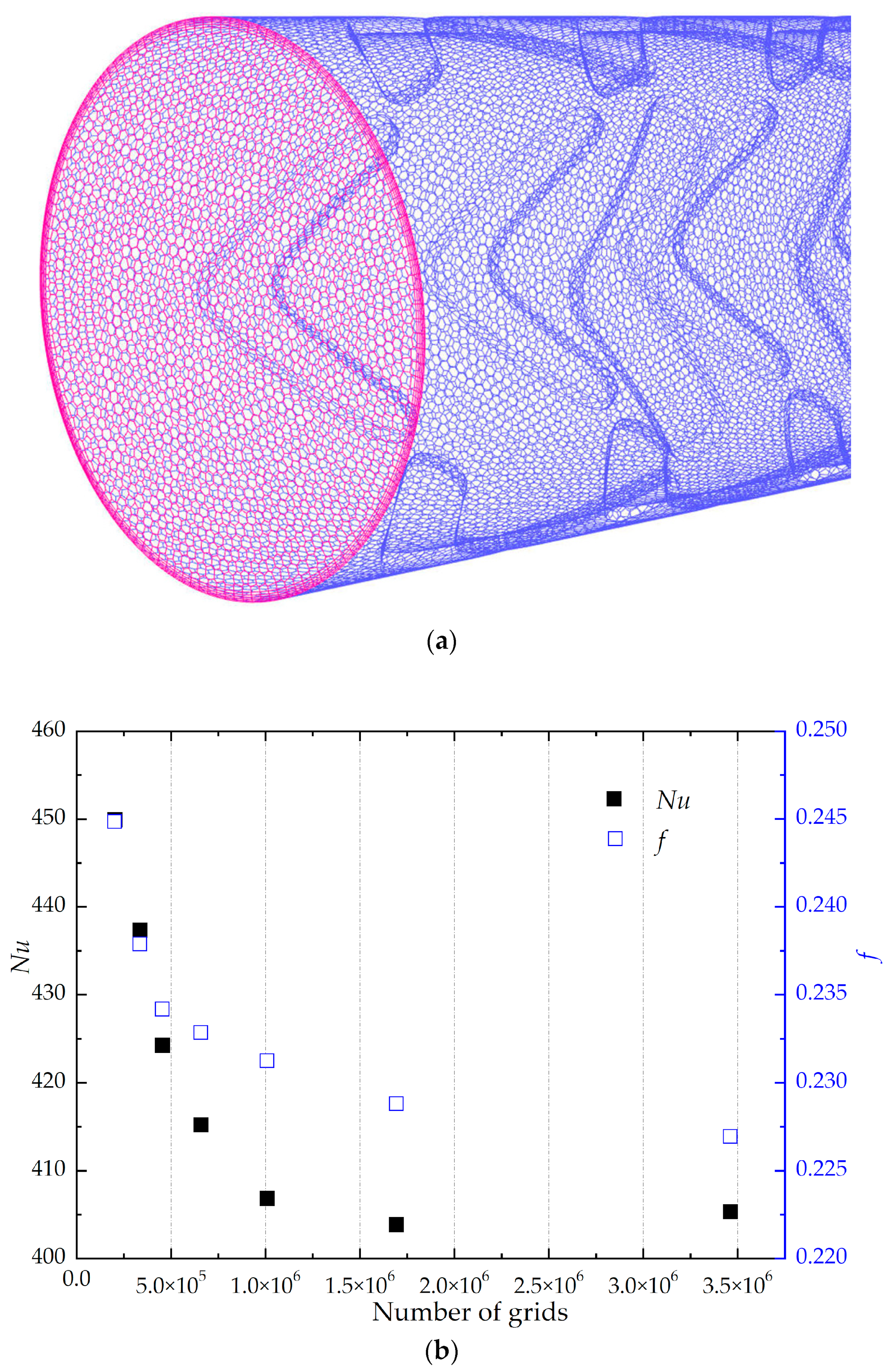
Prior to conducting numerical simulations, the impact of grid resolution on the calculation outcomes is carefully considered. In light of the complex characteristics of micro-ribbed tubes, a polyhedral mesh is utilized to discretize the physical model, leading to a substantial decrease in grid quantity while ensuring the acquisition of high-quality grids. The specific local grid arrangement for the micro-ribbed tube is depicted in Figure 2a. To maintain a y+ value close to 1, five boundary layers are established near the tube wall. The principal geometric parameters of the model include N = 4, e/D = 0.059, and β = 80°. The study examined a series of grid numbers, specifically 201920, 335387, 454715, 657811, 1008275, 1692938, and 3460947. Figure 2b displays the changes in the Nusselt number and friction factor of the heat exchange tube as determined through numerical analysis in relation to the grid number. It was observed that once the grid number surpasses 1692938, there is a slight variation of 0.36% and 0.82% in Nu and f, respectively. Taking into account the precision and efficiency of the numerical simulation, it has been established that a grid number of 1692938 is optimal for subsequent numerical computations.

2.5. Model Validation

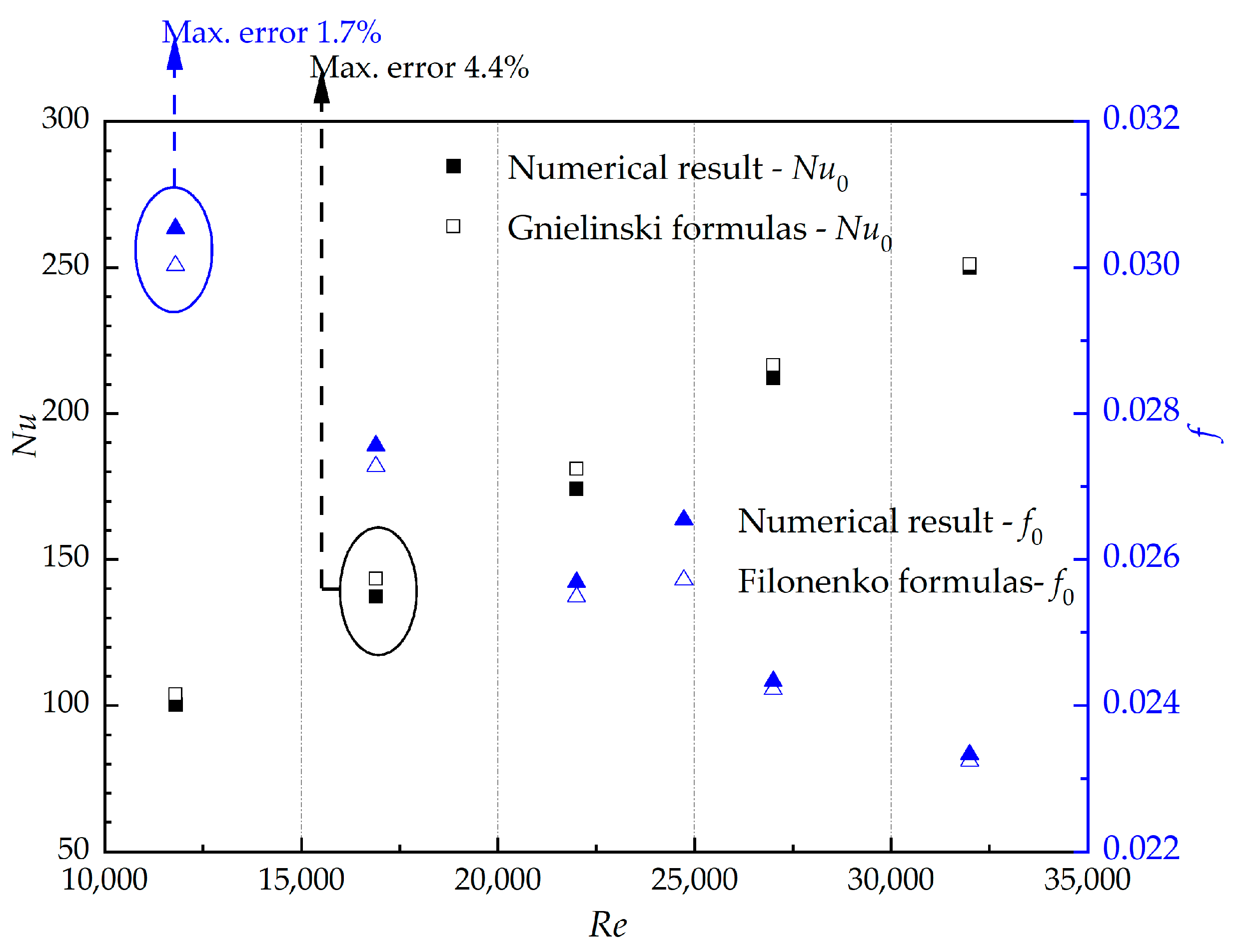
The study utilizes the smooth heat exchanger tube model to assess the accuracy of the numerical simulation process. The Nusselt number Nu0 and friction factor f0 obtained from the numerical analysis are compared with predictions from the Gminelinski and Filonenko formulas. The results, depicted in Figure 3, show a consistent relationship between the numerical solution and the empirical formula as the Reynolds number rises. Furthermore, a high level of agreement is noted with maximum discrepancies of 4.4% and 1.7%, both falling below the 5% threshold. Therefore, the employed numerical solution method can be deemed accurate in this study. It is worth noting that, in the subsequent calculation involving the Nu0 and f0 of smooth heat exchanger tubes, all results are obtained through numerical solutions.

3. Inverse Problem

3.1. Discrete Adjoint Optimization Method

The objective function I for the micro-ribbed tube structural optimization problem in this study is formulated as a combination of the flow calculation variable U and the structural design variable sm, expressed as follows [32]:
I = M U , s m ,
where the variables U and sm satisfy the flow governing equations in the tube, which is expressed as:
R U , s m = 0 .
In the process of structure optimization, the flow governing equation R is taken as a constraint and Lagrange multiplier η is introduced to construct the extreme value function of the objective function:
I = M U , s m η R U , s m .
with the conjugate gradient method, which is widely used in inverse heat transfer problems, a conjugate gradient method optimization process based on adjoint optimization method is constructed. In terms of research contents in this paper, the objective function is mainly on the relationship between the design variable, which depends on the above set U / s m . As the number of structural design variables sm increases (m = 1, 2, …, M), U / s m became the largest amount of calculation, the extreme value function (26) for U / s m merge sort, get it:
d I d s m = M s m η T R s m + M U η T R U U s m ,
The Lagrange multiplier η in Equation (27) is obtained by taking its first partial derivative with respect to variables U and sm and making it 0. In conjunction with Equation (26), we can obtain:
M U η T R U = 0 .
then the above formula (28) can be arranged as:
d I d s m = M s m η T R s m .
By solving the flow control Equation (25) to get M / s m and R / s m , and solving the adjoint Equation (29) to get the adjoint factor, we can get the gradient value of the objective function for the design variable, which can be used to perform conjugate gradient optimization process instead of relying on the number of design variables.

3.2. Adjoint Equation Solving

The purpose of solving the adjoint equation is mainly to solve the adjoint factors mentioned above, which are derived through the coupled flow governing equation and the objective function M. Take the continuity equation, momentum equation, and energy equation in vector form, and set their adjoint factors to η, ξ, π, respectively, to get the following expression [32,33]:
I s m = Ω M δ r r m d Ω + Ω η U d Ω + Ω ξ U U + p I μ + μ T U + 2 3 k δ i j d Ω + Ω π U T a 2 T d Ω .
where δ(rrm) is the Dirac function. When the design variable changes δs, the corresponding temperature change is δT, the velocity change is δU, and the objective function becomes I + δI, then
I + δ I = Ω M + δ M δ r r m d Ω + Ω η U + δ U d Ω + Ω ξ U + δ U U + δ U + p I μ + μ T U + δ U + 2 3 k δ i j d Ω + Ω π U + δ U T + δ T a 2 T + δ T d Ω .
subtract Equation (30) from Equation (31) to get:
δ I = Ω δ M d Ω + Ω η δ U d Ω + Ω ξ U δ U + δ U U + δ U μ + μ t δ U d Ω + Ω π U δ T + δ U T + δ T a 2 δ T d Ω .
Since δT and δU are arbitrary, their coefficients are 0. Ignoring the quadratic terms in the equation, the following adjoint governing equation is obtained:
U π + a 2 η = 0 ,
η is used to represent the adjoint factor and the adjoint equation is obtained by expanding it in a rectangular coordinate system:
u η x + v η y + w η z + a 2 η x 2 + a 2 η y 2 + a 2 η z 2 = 0 .
the boundary conditions of the adjoint equation are:
z = 0, η (x, y, z) = 0;
x = y = 0, η (x, y, z) = 0;
z = L ,   M s m + η w + a η z = 0 ; x
x = y = r ,   u = v = 0 ,   η x + η y = 0 ;
x = y = e, η (x, y, z) = 0.

3.3. Design Variables Optimization Process
The performance evaluation criteria are adopted in the coupling optimization, and the objective function is defined as:
I = P E C = N u / N u 0 f / f 0 1 / 3 .
At the k + 1 step iteration, the relative roughness height (e/D) of the ith micro rib was defined as:
(e/D) ik+1= (e/D) ikαkdik, (i = 1, 2, …, M)
where αk is the search step of the iteration, αk = 0.0001 is defined according to the complexity of the model. dik is the search direction and its formula is as follows:
d i k = I e / D i , k = 0 d i k = I e / D i + γ k d k 1 , k 0 ,
γ is the conjugate coefficient, its formula is as follows:
γ k = I e / D i k / I e / D i k 1 2 .
The convergence criterion for inverse optimization is set as:
Δ I < ε ,
where ε is a minimum value greater than zero. When the gradient of the objective function is less than this value, it is considered that the objective function no longer changes with the iteration. At this time, iteration can be stopped, and the inverse optimization result can be obtained. MATLAB 2019a is used to edit the calculation code.
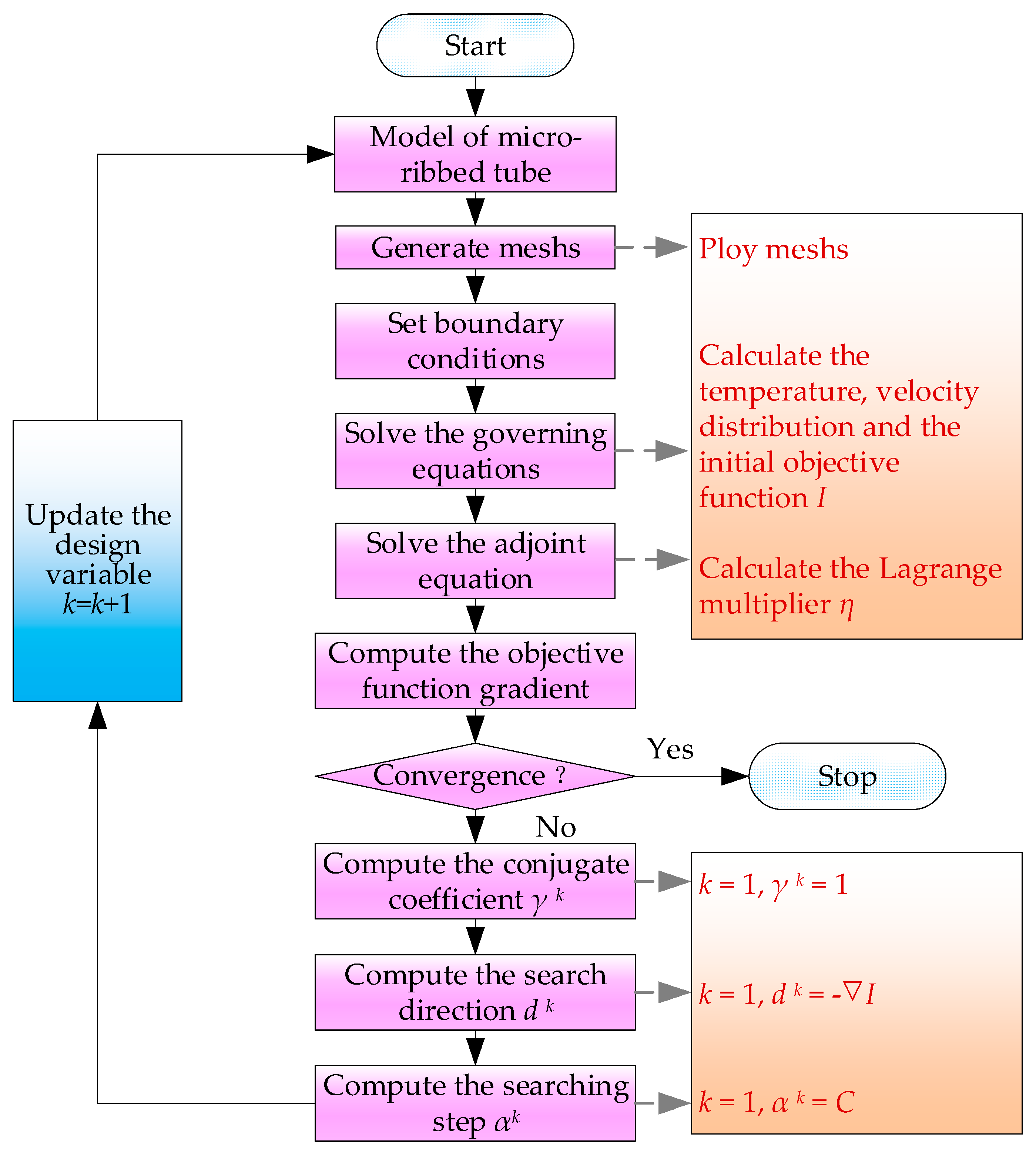
The main optimization steps of this paper are shown in Figure 4, and detailed steps are described as follows:
Step 1: Build the micro-ribbed tube model, and determine the coupling impacts of variables by the numerical solution;
Step 2: Given a relatively small positive number ε and select initial relative roughness height (e/D) from the results of numerical solution, and compute the initial objective function (I);
Step 3: Solve the adjoint equation and calculate the gradient that satisfies the adjoint factor (η). If the convergence criterion is satisfied, iteration is stopped; otherwise, the procedure continues to step 4;
Step 4: Compute the conjugate coefficients γk and the search directions dk. For the initial step, set γ1 = 1 and d1 = − I ;
Step 5: Update the relative roughness height (e/D) of the ith micro rib by equation (36) and then return to step (1).
Figure 4. The flow chart of the optimization process.
Energies 17 05102 g004

4. Results and Discussions

4.1. Effect of Micro-Rib Structures on the Thermo-Hydraulic Performance

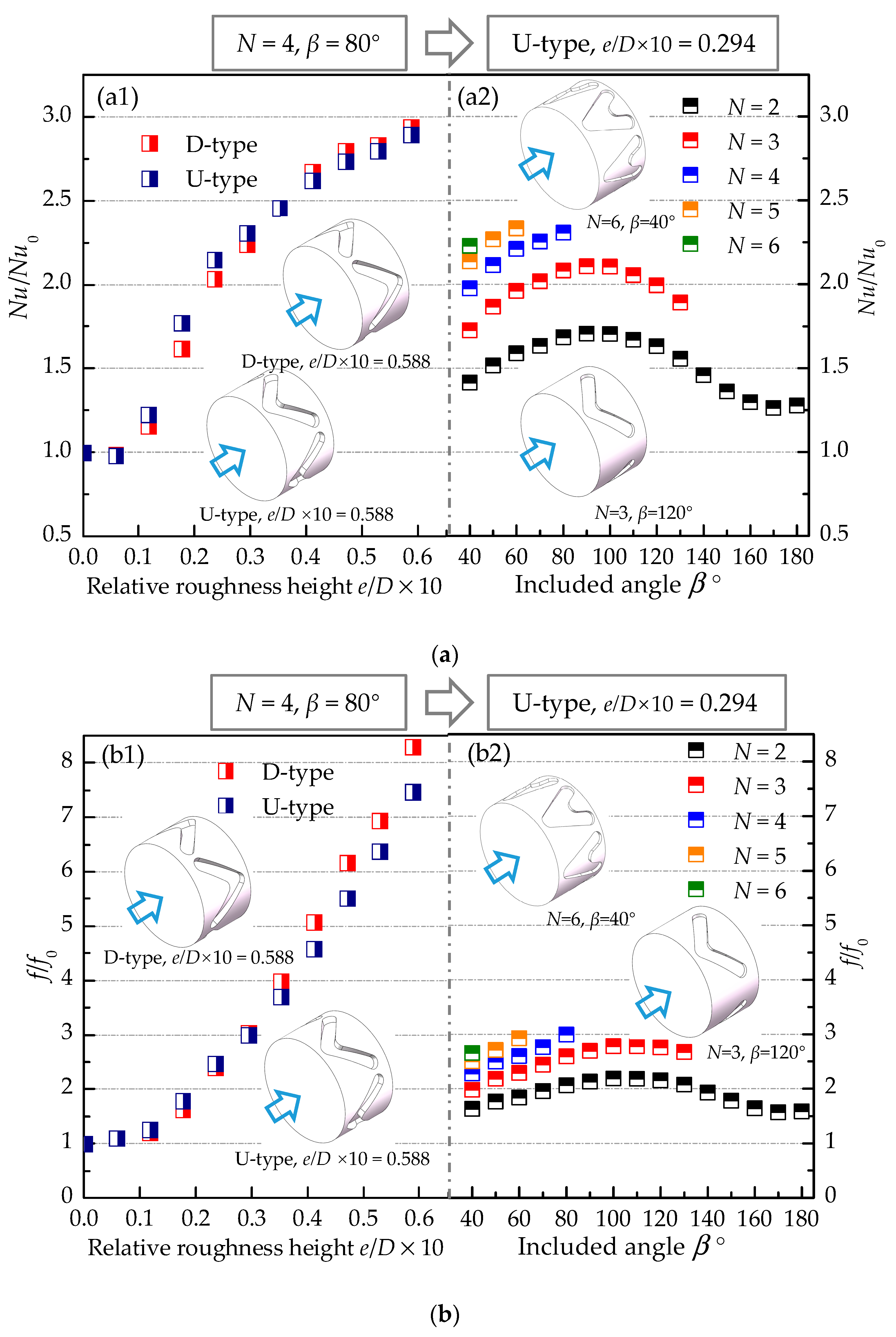
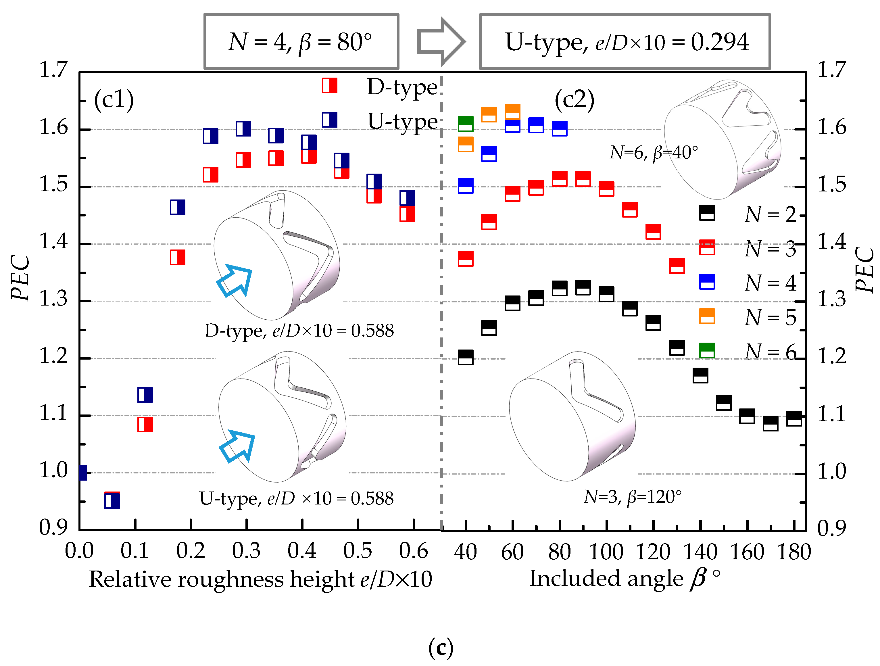
The thermo-hydraulic characteristics of the micro-ribbed tube under different structural parameters are illustrated in Figure 5. Specifically, Figure 5a1,b1,c1 depict the variations in heat transfer effect (Nu/Nu0), friction factor (f/f0), and PEC within tubes with varying relative roughness height (e/D) of micro-ribs under different arrangements. It is observed that there is minimal disparity in flow heat transfer characteristics between different arrangements, with slightly superior PEC exhibited by the U-type arrangement. Furthermore, there is an optimal value of e/D = 0.0294 for micro-ribs. Overall, the e/D of the micro-rib has a great influence on the flow heat transfer characteristics in the tube.
The variations in flow heat transfer performance of the micro-ribbed tube with the inclined angle (β) under different circumferential rows (N) are depicted in Figure 5a2,b2,c2. Two noteworthy observations can be made from the figure. Firstly, for a given β, Nu/Nu0, f/f0, and PEC all exhibit a gradual increase with N. Secondly, there exists an optimal value of β = 60° that maximizes the PEC of the N = 5 micro-ribbed tube.
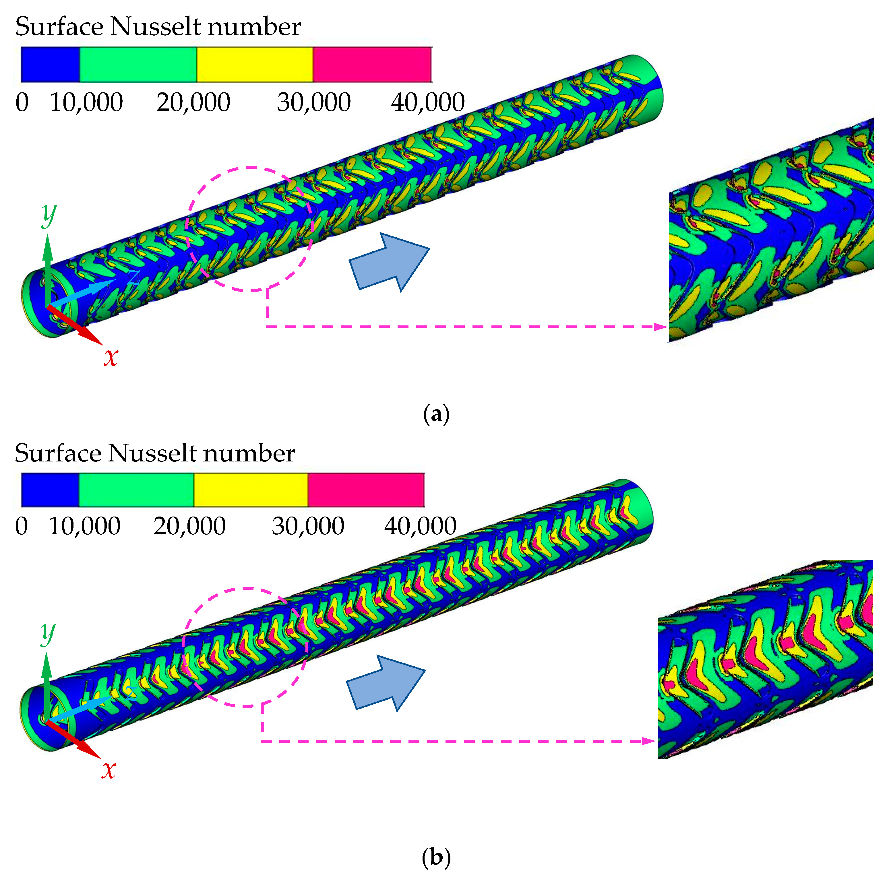
The distribution of surface Nusselt numbers under various arrangements is depicted in Figure 6. It is evident that regions with elevated Nusselt numbers are concentrated around the micro-ribs. Initially, the Nusselt number is low as the fluid encounters the micro-ribs, but it gradually increases in the direction of flow, displaying an approximately periodic distribution. Among the different arrangements of micro-ribbed tubes, the U-type arrangement shows notably larger areas with higher Nusselt numbers. Specifically, as illustrated in Figure 5a, the configuration of U-type resulted in improved heat transfer efficiency. Additionally, the introduction of micro-ribs promotes the formation of longitudinal vortices, disrupting the boundary layer in close proximity to the tube wall and facilitating fluid mixing between the tube wall and its center, thereby enhancing heat transfer within the tube. Longitudinal vortices are typically generated at sharp corners [28]. Consequently, in the D-type arrangement, enhanced heat transfer efficiency is observed between adjacent micro-ribs, whereas for U-type arrangements, it occurs at the inclined angle of the micro-ribs.
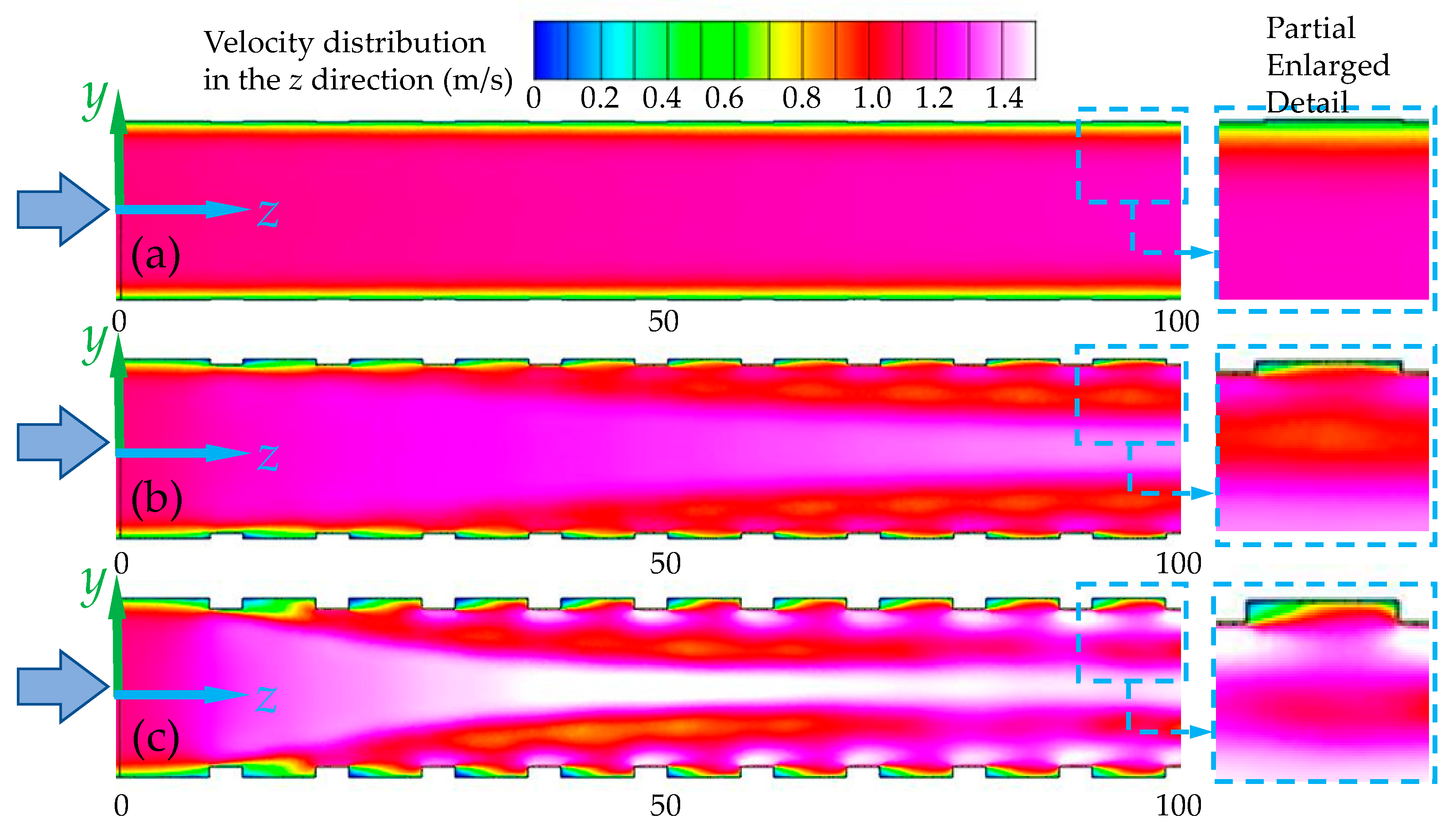
The study delves deeper into the influence of relative roughness height (e/D) on thermo-hydraulic performance. Figure 7 illustrates the velocity distribution along the flow direction (z = 0~100 mm) of the x = 0 mm profile for various e/D values. At e/D = 0.0059, depicted in figure (a), a decrease in flow velocity is observed, leading to suboptimal heat transfer performance. In contrast, an increase in e/D, as shown in figure (b), results in enhanced fluid mixing and velocity due to the introduction of micro-ribs, consequently improving heat transfer efficiency. It is imperative to recognize that an increase in the ratio of rib height to hydraulic diameter (e/D) results in heightened mixing efficiency and escalating flow velocity. Nevertheless, the influence of the micro-rib on fluid friction factor becomes more pronounced, as depicted in the partially enlarged figure on the right side of figure (c). Consequently, an optimal value for e/D exists.
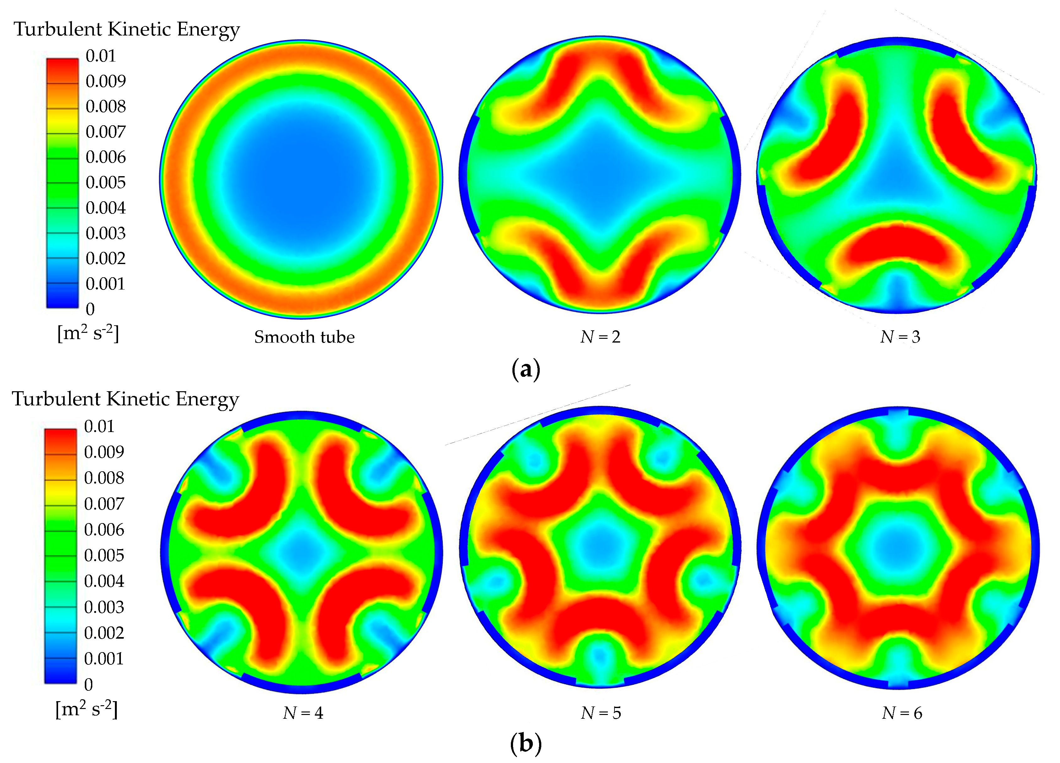
The turbulent kinetic energy (TKE) distributions of tubes with varying N-values are compared in Figure 8 at the z = 105 mm profile. It is evident that the ribbed tube demonstrates notably higher TKE values in comparison to the smooth tube. This enhancement in TKE can be attributed to the presence of micro-ribs, which promote the formation of longitudinal vortices, leading to improved fluid mixing and disruption of the thermal boundary layer. Additionally, it is noted that the area of low TKE values decreases with an increase in the N-value.
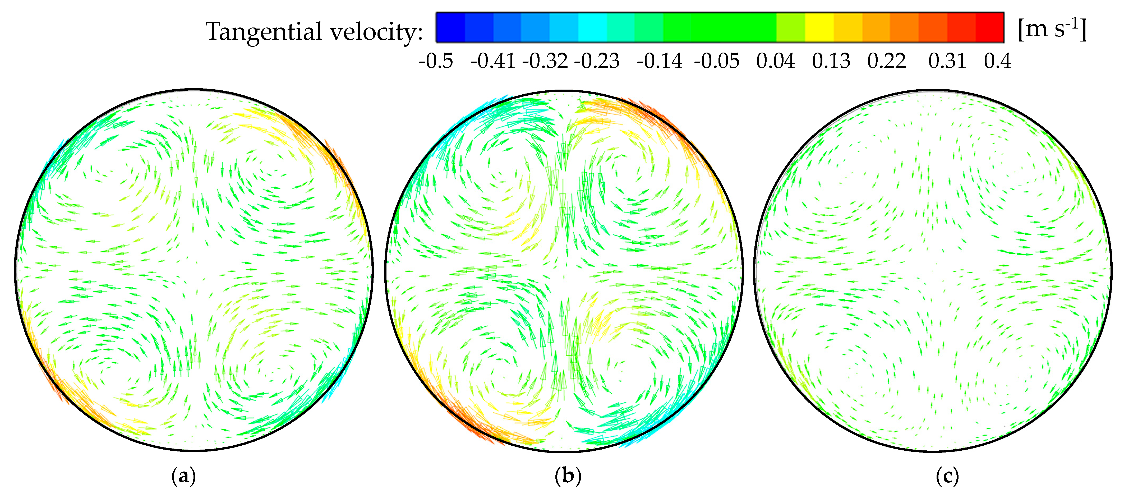
The impact of the inclined angle β on the thermo-hydraulic performance was investigated, using a micro-ribbed tube with N = 2 as an illustrative example. The velocity vector over the profile z = 200 mm at β = 40°, 90°, and 160° is depicted in Figure 9. It is observed that the longitudinal vortices induced by micro-ribs enhance the flow mixing between the main flow and the near-wall zone. In addition, the velocity vector exhibits an increases and elongation as β increases. When β = 90°, the magnitude of the velocity vector significantly increases, leading to a substantial augmentation in the longitudinal vortex structure, which enhance the convective heat transfer characteristics within the tube. This phenomenon is also clearly depicted in Figure 5. The velocity vector significantly decreases and contracts as the included angle continues to increase, as depicted in figure (c). Consequently, the longitudinal vortex structure tends to dissipate, leading to a weakened flow mixing effect and diminished heat transfer characteristics.
Furthermore, analysis of the tangential velocity contour reveals that the micro-ribs generate counterflows along the tangential direction of the section, corresponding to the flow pattern of the longitudinal vortex near the tube wall. This tangential flow facilitates the disruption and breakdown of the boundary layer, thereby enhancing heat transfer performance. Notably, when β = 90°, the maximum velocity is significantly higher compared to the other conditions, resulting in superior heat transfer performance. Conversely, at β = 160°, the tangential velocity is markedly reduced.

4.2. Coupling Optimization of the Rib Relative Roughness Height (e/D)

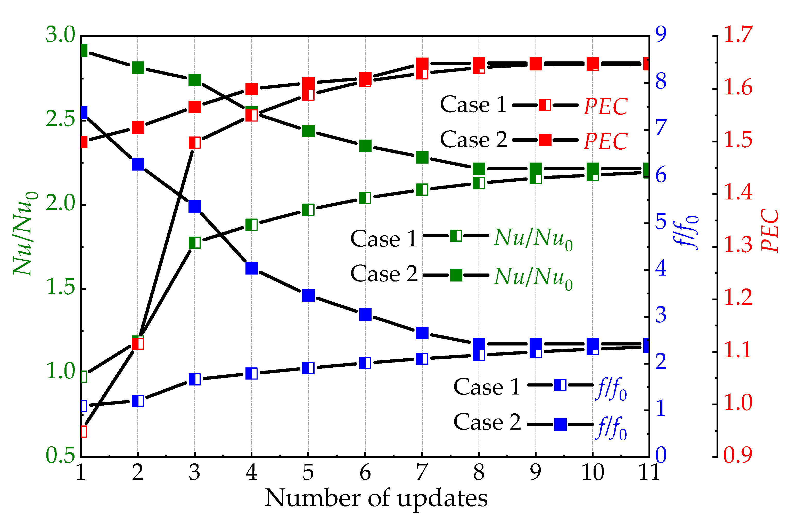
Figure 10 illustrates the optimization process of the relative roughness height (e/Di, i = 1–19), where the maximum value of PEC is achieved at the optimal e/D values. It can be observed that consistent optimization parameters were obtained regardless of different initial values (Case 1: U-type, e/D = 0.00588, N = 5, β = 60° and Case 2: U-type, e/D = 0.05882, N = 5, β = 60°). The optimized results of the various e/Di (i = 1–19) are presented in Table 2. There is a major temperature difference between the fluid and tube wall upon entry, indicating excellent heat transfer performance. Consequently, the values of e/Di (i = 1–4) exhibit remarkable similarity along the flow direction. Along the flow direction, the optimized e/Di (i = 5–19) is gradually increased to generate greater disturbance to the fluid, thereby increasing the thermo-hydraulic performance, where the difference between the minimum and maximum e/Di (i = 1–19) is about 5.7%.

4.3. Analysis of Entransy Dissipation Value of the Optimized Tube

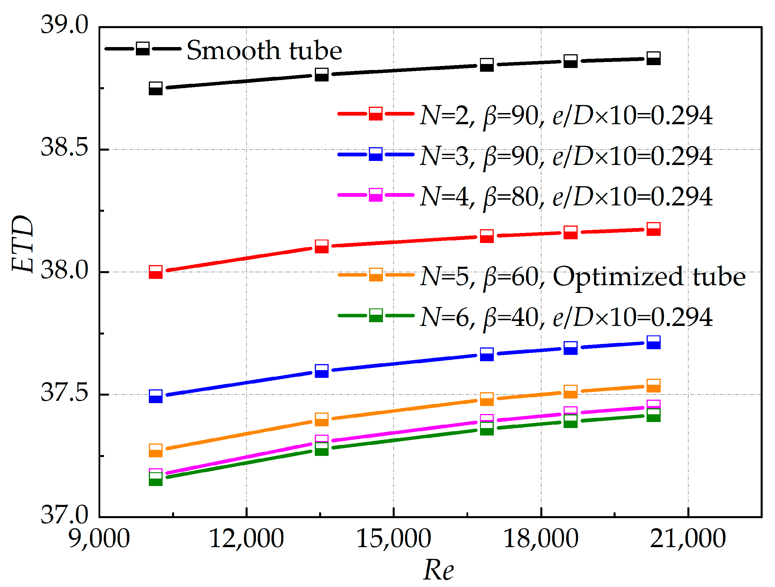
The relationship between equivalent thermal diffusivity (ETD) and Reynolds number in cases demonstrating optimal heat transfer performance (Nu/Nu0) is illustrated in Figure 11, with the selected tube configuration (N = 5, β = 60°) used to analyze the fundamental aspects of the heat transfer process. It is evident that ETD gradually increases with an increase in the Reynolds number. All micro-ribbed tubes exhibit lower ETD values compared to smooth tubes, suggesting that the incorporation of micro-ribs enhances heat transfer efficiency. Additionally, ETD decreases as the number of circumferential rows of micro-ribs increases. However, for achieving maximum PEC, the optimized tube design compromises a portion of its heat transfer performance.

4.4. Comparisons with Other Studies

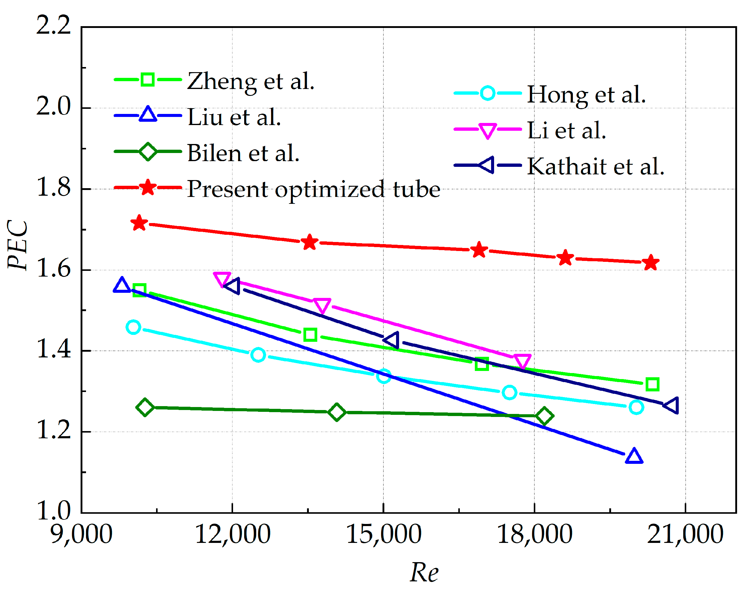
The comparison between the optimized tube in this study and the heat transfer enhancement structure proposed in the literature is presented in Figure 12 (Re = 10,151–20,302). All the structures with the best thermo-hydraulic performance in the literature studies include the discontinuous ribbed tube designed by Zheng et al. [17]; the undulating internal micro-ribbed tube studied by Hong et al. [20] (Case 19); the inclined micro-ribbed tube proposed by Liu et al. [18] (CIR); the elliptical concave tube obtained by Li et al. [37]. In addition, Bilen [38] studied semi-circular fluted tubes and Kathait [39] obtained discrete inclined micro-ribbed tubes.
The optimized micro-ribbed tube exhibits a higher PEC value compared to the others at Re > 10,000, with an increasing difference that gradually escalates with the Re. Notably, when compared to the study of Zheng et al. [17] conducted under similar Re, the PEC value within the tube demonstrates an enhancement of approximately 10.65–22.78% (Re = 10,151–20,302).

5. Conclusions

A novel micro-rib structure featuring a circular arc is suggested for enhancing the efficiency of shell-and-tube heat exchangers. Through an examination of the interplay between various structural parameters of the micro-ribs, it is determined that the relative roughness height (e/D) holds significant influence on the thermo-hydraulic performance. A numerical solution approach utilizing the discrete adjoint method is developed to optimize the different e/Di values (i = 1–19) of the multiple micro-ribs. The primary findings are as follows:
(1)
The relationship between the micro-rib structural parameters and the thermo-hydraulic performance of the tube is highly interconnected. Specifically, the method of arrangement (D-type and U-type) dictates the optimal location for heat transfer effectiveness, with an increase in the number of circumferential rows (N) leading to improved fluid mixing near the tube wall and center. The inclined angle (β) can create a longitudinal vortex to enhance heat transfer, while the height (e) of the micro-rib is a critical structural parameter influencing flow and heat transfer within the tube.
(2)
The discrete adjoint method offers a numerical solution that is advantageous for optimizing the coupling of multiple parameters in micro-ribbed tubes. By prioritizing the PEC as the objective function, it allows for the creation of a unique structure with varying rib heights. Interestingly, varying initial values can result in similar objective function values. The optimized ribbed tube shows a significant 64.9% improvement in PEC compared to a smooth tube. The range between the minimum and maximum e/Di (i = 1–19) is approximately 5.7%.
(3)
The optimized micro-ribbed design sacrifices some heat transfer performance; however, the optimized tube exhibits a higher PEC value compared to previous studies at Reynolds numbers greater than 10,000. More specifically, the PEC is 10.65% to 22.78% greater than that of the existing structure within the same range.
(4)
Finally, it is noteworthy that the concept of multi-parameter coupling optimization presented in this paper can be extended to other inverse convective heat transfer problems governed by analogous governing equations. For instance, the design of multiple pin-fin heat exchanger flow channels can be optimized by selecting heat transfer performance and flow pressure drop as objective functions. This approach can facilitate the cooling of localized high-temperature hotspots or enhance the overall heat transfer rate, thereby contributing to the design of compact heat exchangers, electronic device cooling systems, and other related applications.

Author Contributions

Z.W.: Software, writing—original draft preparation, visualization, validation, formal analysis, and investigation; X.Y.: Conceptualization, methodology, and writing—review and editing; X.G., Q.S. and Y.L.: Resources and supervision; X.H. and Z.L.: Data curation and project administration. All authors have read and agreed to the published version of the manuscript.

Funding

This research received no external funding.

Data Availability Statement

All data to support the results of this study are included in this article.

Conflicts of Interest

The authors affirm the absence of any competing interests.

Abbreviations

Nomenclature Abbreviation
Cp,vspecific heat, J kg−1 K−1DAMDiscrete Adjoint Method
dsearch directionD-typeCommon–Flow–Down type
Dtube diameter, mmETDEquivalent Temperature Difference
Dhhydraulic diameter, mmFVMFinite Volume Method
erib height, mmIHTPInverse Heat Transfer Problem
EhentransyPECPerformance Evaluation Criteria
ffriction factorTKETurbulent Kinetic Energy
hconvection heat transfer coefficient, W m−2 K−1U-typeCommon–Flow–Up type
Iturbulence intensity;
objective function
Greek symbols
llength of the extension, mmαsearch step size
Llength of the heating section, mmβinclined angle, °
Mmass flow, kg/sγconjugate coefficient
Ncircumferential rowsεminimum value
NuNusselt numberλthermal conductivity,
W m−1·K−1
pspacing of ribs, mmμfluid viscosity, Pa·s
PrPrandtl numberρair density, kg m−3
qaverage heat flux, W m−2ηadjoint factor
Qheat transfer rate, WSubscripts
rcircular-arc radius, mm0smooth tube
ReReynolds numberffluid area
smdesign variableioptimal value
Ttemperature, Kininlet
Δtmaverage temperature differenceinitinitial
u, v, ωvelocity components, m s−1kiteration steps
wrib width, mmoptoptimal value
outoutlet
wtube wall

References

  1. Cheng, J.; Qian, Z.; Wang, Q. Analysis of heat transfer and flow resistance of twisted oval tube in low Reynolds number flow. Int. J. Heat Mass Transf. 2017, 109, 761–777. [Google Scholar] [CrossRef]
  2. Liu, P.; Zheng, N.; Shan, F.; Liu, Z.; Liu, W. An experimental and numerical study on the laminar heat transfer and flow characteristics of a circular tube fitted with multiple conical strips inserts. Int. J. Heat Mass Transf. 2018, 117, 691–709. [Google Scholar] [CrossRef]
  3. Huang, S.; Deng, M.; Chen, Z.; Yang, D.; Xu, Y.; Lan, N. Experimental and numerical investigations on thermal-hydraulic performance of three-dimensional overall jagged internal finned tubes. Micromachines 2024, 15, 513. [Google Scholar] [CrossRef] [PubMed]
  4. Xu, K.; Sun, X.; Meng, H. Conjugate heat transfer, endothermic fuel pyrolysis and surface coking of aviation kerosene in ribbed tube at supercritical pressure. Int. J. Therm. Sci. 2018, 132, 209–218. [Google Scholar] [CrossRef]
  5. Cao, Y.; Ayed, H.; Anqi, A.E.; Tutunchian, O.; Dizaji, H.S.; Pourhedayat, S. Helical tube-in-tube heat exchanger with corrugated inner tube and corrugated outer tube; experimental and numerical study. Int. J. Therm. Sci. 2021, 170, 107139. [Google Scholar] [CrossRef]
  6. Xu, W.; Wang, S.; Liu, G.; Zhang, Q.; Lu, H. Experimental and numerical investigation on heat transfer of therminol heat transfer fluid in an internally four-head ribbed tube. Int. J. Therm. Sci. 2017, 116, 32–44. [Google Scholar] [CrossRef]
  7. Córcoles, J.I.; Belmonte, J.F.; Molina, A.E.; Almendros-Ibáñez, J.A. Influence of corrugation shape on heat transfer performance in corrugated tubes using numerical simulations. Int. J. Therm. Sci. 2019, 137, 262–275. [Google Scholar] [CrossRef]
  8. Li, M.; Khan, T.S.; Al-Hajri, E.; Ayub, Z.H. Single phase heat transfer and pressure drop analysis of a dimpled enhanced tube. Appl. Therm. Eng. 2016, 101, 38–46. [Google Scholar] [CrossRef]
  9. Góngora-Gallardo, G.; Castro-Gil, M.; Colmenar-Santos, A.; Tawfik, M. Efficiency factors of solar collectors of parallel plates for water. Sol. Energy 2013, 94, 335–343. [Google Scholar] [CrossRef]
  10. Okafor, I.F.; Dirker, J.; Meyer, J.P. Influence of non-uniform heat flux distributions on the secondary flow, convective heat transfer and friction factors for a parabolic trough solar collector type absorber tube. Renew. Energy 2017, 108, 287–302. [Google Scholar] [CrossRef]
  11. Gholami, A.; Wahid, M.A.; Mohammed, H.A. Thermal–hydraulic performance of fin-and-oval tube compact heat exchangers with innovative design of corrugated fin patterns. Int. J. Heat Mass Transf. 2017, 106, 573–592. [Google Scholar] [CrossRef]
  12. Raj, R.; Lakshman, N.S.; Mukkamala, Y. Single phase flow heat transfer and pressure drop measurements in doubly enhanced tubes. Int. J. Therm. Sci. 2015, 88, 215–227. [Google Scholar] [CrossRef]
  13. Hosseini, A.M.; Faghih Khorasani, A. Experimental and numerical study of the rib effect in a gas-gas heat exchanger performance used in a sponge iron production plant (MIDREX). Proc. Inst. Mech. Eng. A J. Pow. 2021, 235, 1747–1758. [Google Scholar] [CrossRef]
  14. Jia, B. Numerical Research on Integrated Heat Transfer Performance of the New Inner-Ribs Tubes. Master’s Thesis, Zhengzhou University, Zhengzhou, China, 2015. [Google Scholar]
  15. Liu, B.; Shi, C.; Liu, W.; Liu, Z. Research on heat exchange and flow resistance performance and multi-objective structural optimization of oval twist tube with two fins. J. Northeast Elec. Pow. Nniver. 2022, 42, 37–45. [Google Scholar] [CrossRef]
  16. Zheng, N.; Liu, P.; Shan, F.; Liu, Z.; Liu, W. Heat transfer enhancement in a novel internally grooved tube by generating longitudinal swirl flows with multi-vortexes. Appl. Therm. Eng. 2016, 95, 421–432. [Google Scholar] [CrossRef]
  17. Zheng, N.; Liu, P.; Shan, F.; Liu, Z.; Liu, W. Effects of rib arrangements on the flow pattern and heat transfer in an internally ribbed heat exchanger tube. Int. J. Therm. Sci. 2016, 101, 93–105. [Google Scholar] [CrossRef]
  18. Liu, P.; Lv, J.; Shan, F.; Liu, Z.; Liu, W. Effects of rib arrangements on the performance of a parabolic trough receiver with ribbed absorber tube. Appl. Therm. Eng. 2019, 156, 1–13. [Google Scholar] [CrossRef]
  19. Jin, G.; Bao, Y.; Guo, S.; Wu, X. Numerical simulation of the intensified heat exchange of cylindrical inner ribs and analysis of the entransy dissipation. J. Eng. Therm. Energy Pow. 2018, 33, 8–14. [Google Scholar] [CrossRef]
  20. Hong, Y.; Du, J.; Wang, S.; Huang, S. Heat transfer and flow behaviors of a wavy corrugated tube. Appl. Therm. Eng. 2017, 126, 151–166. [Google Scholar] [CrossRef]
  21. Du, J.; Hong, Y.; Huang, S.M.; Ye, W.B.; Wang, S. Laminar thermal and fluid flow characteristics in tubes with sinusoidal ribs. Int. J. Heat Mass Transf. 2018, 120, 635–651. [Google Scholar] [CrossRef]
  22. Wang, X.D.; Huang, Y.X.; Cheng, C.H.; Jang, J.Y.; Lee, D.J.; Yan, W.M.; Su, A. Flow field optimization for proton exchange membrane fuel cells with varying channel heights and widths. Electrochim. Acta 2009, 54, 5522–5530. [Google Scholar] [CrossRef]
  23. Leng, C.; Wang, X.D.; Wang, T.H.; Yan, W.M. Optimization of thermal resistance and bottom wall temperature uniformity for double-layered microchannel heat sink. Energy Convers. Manag. 2015, 93, 141–150. [Google Scholar] [CrossRef]
  24. Lin, L.; Chen, Y.Y.; Zhang, X.X.; Wang, X.D. Optimization of geometry and flow rate distribution for double-layer microchannel heat sink. Int. J. Therm. Sci. 2014, 78, 158–168. [Google Scholar] [CrossRef]
  25. Min, T.; Chen, X.; Sun, Y.; Huang, Q. A numerical approach to solving an inverse heat conduction problem using the Levenberg-Marquardt algorithm. Math. Probl. Eng. 2014, 2014, 626037. [Google Scholar] [CrossRef]
  26. Cui, M.; Zhao, Y.; Xu, B.; Gao, X. A new approach for determining damping factors in Levenberg-Marquardt algorithm for solving an inverse heat conduction problem. Int. J. Heat Mass Transf. 2017, 107, 747–754. [Google Scholar] [CrossRef]
  27. Zhang, D.D.; Zhang, J.H.; Liu, D.; Zhao, F.Y.; Wang, H.Q.; Li, X.H. Inverse conjugate heat conduction and natural convection inside an enclosure with multiple unknown wall heating fluxes. Int. J. Heat Mass Transf. 2016, 96, 312–329. [Google Scholar] [CrossRef]
  28. Yang, X.; Hu, J.; Fan, Y.; Min, C.; Wang, K. Enhanced heat dissipation of ribbed channels based on the coupling optimization of multiple structural parameters. Appl. Therm. Eng. 2023, 235, 121362. [Google Scholar] [CrossRef]
  29. Seo, J.W.; Afzal, A.; Kim, K.Y. Efficient multi-objective optimization of a boot-shaped rib in a cooling channel. Int. J. Therm. Sci. 2016, 106, 122–133. [Google Scholar] [CrossRef]
  30. Ansari, M.; Bazargan, M. Optimization of flat plate solar air heaters with ribbed surfaces. Appl. Therm. Eng. 2018, 136, 356–363. [Google Scholar] [CrossRef]
  31. Ponce-Ortega, J.M.; Serna-González, M.; Jiménez-Gutiérrez, A. Use of genetic algorithms for the optimal design of shell-and-tube heat exchangers. Appl. Therm. Eng. 2009, 29, 203–209. [Google Scholar] [CrossRef]
  32. Nabi, S.; Grover, P.; Caulfield, C.P. Adjoint-based optimization of displacement ventilation flow. Build. Environ. 2017, 124, 342–356. [Google Scholar] [CrossRef]
  33. Papoutsis-Kiachagias, E.M.; Giannakoglou, K.C. Continuous adjoint methods for turbulent flows, applied to shape and topology optimization: Industrial applications. Arch. Comput. Method Eng. 2014, 23, 255–299. [Google Scholar] [CrossRef]
  34. Menter, F.R. Two-equation eddy-viscosity turbulence models for engineering applications. AIAA J. 1994, 32, 1598–1605. [Google Scholar] [CrossRef]
  35. Guo, Z.Y.; Tao, W.Q.; Shah, R.K. The field synergy (coordination) principle and its applications in enhancing single phase convective heat transfer. Int. J. Heat Mass Transf. 2005, 48, 1797–1807. [Google Scholar] [CrossRef]
  36. He, Y.L.; Tao, W.Q. Numerical studies on the inherent interrelationship between field synergy principle and entransy dissipation extreme principle for enhancing convective heat transfer. Int. J. Heat Mass Transf. 2014, 74, 196–205. [Google Scholar] [CrossRef]
  37. Li, M.; Khan, T.S.; Hajri, E.A.; Ayub, Z.H. Geometric optimization for thermal–hydraulic performance of dimpled enhanced tubes for single phase flow. Appl. Therm. Eng. 2016, 103, 639–650. [Google Scholar] [CrossRef]
  38. Bilen, K.; Cetin, M.; Gul, H.; Balta, T. The investigation of groove geometry effect on heat transfer for internally grooved tubes. Appl. Therm. Eng. 2009, 29, 753–761. [Google Scholar] [CrossRef]
  39. Kathait, P.S.; Patil, A.K. Thermo-hydraulic performance of a heat exchanger tube with discrete corrugations. Appl. Therm. Eng. 2014, 66, 162–170. [Google Scholar] [CrossRef]
Figure 1. Schematic diagram of the numerical calculation model: (a) calculation model; (b) Common–Flow–Down (D-type) arrangement; (c) Common–Flow–Up (U-type) arrangement.
Energies 17 05102 g001
Figure 2. Grid independence verification: (a) local grid diagram; (b) the variation of Nu and f with the number of grids.
Energies 17 05102 g002
Figure 3. The results of the numerical solution and the empirical formula are compared in the smooth heat exchange tube.
Energies 17 05102 g003
Figure 5. Thermo-hydraulic characteristics for varying structural parameters: (a1) Nu/Nu0 vs. e/D at N = 4, β = 80°, (a2) Nu/Nu0 vs. β at U-type and e/D × 10 = 0.294; (b1) f/f0 vs. e/D at N = 4, β = 80°, (b2) f/f0 vs. β at U-type and e/D × 10 = 0.294; (c1) PEC vs. e/D at N = 4, β = 80°, (c2) PEC vs. β at U-type and e/D × 10 = 0.294.
Energies 17 05102 g005aEnergies 17 05102 g005b
Figure 6. Distribution of surface Nusselt number (e/D = 0.0294, N = 4, β = 80°): (a) D-type arrangement; (b) U-type arrangement.
Energies 17 05102 g006
Figure 7. Velocity field of x = 0 mm profile at different e/D: (a) e/D = 0.0059; (b) e/D = 0.0294; (c) e/D = 0.0588.
Energies 17 05102 g007
Figure 8. TKE distributions of the smooth and different N-value tubes at z = 105 mm profile: (a) Smooth tube and N = 2–3; (b) N = 4–6.
Energies 17 05102 g008
Figure 9. Tangential velocity vectors at the cross-section z = 200 mm with various β: (a) β = 40°; (b) β = 90°; (c) β = 160°.
Energies 17 05102 g009
Figure 10. Coupling optimization process of various e/Di (i = 1–19).
Energies 17 05102 g010
Figure 11. Variations of ETD vs. Re.
Energies 17 05102 g011
Figure 12. Comparisons of PEC in optimized tubes with the values in previous literatures [17,18,20,37,38,39].
Energies 17 05102 g012
Table 1. Geometric parameters of the micro-ribbed tube.
ParametersSymbolValue
Rib lengthI7 mm
Rib heighte0.1~1 mm
Rib widthw2 mm
Pitchp10 mm
Radius of arc r1 mm
Inclined angleβ60~180°
Circumferential rowsN2~6
Table 2. Optimized results of the various e/Di (i = 1–19).
e/D1e/D2e/D3e/D4e/D5e/D6e/D7e/D8e/D9e/D10
0.023350.023270.023300.023370.023460.023580.023690.023800.023900.02399
e/D11e/D12e/D13e/D14e/D15e/D16e/D17e/D18e/D19
0.024040.024110.024170.024220.024310.024380.024440.024520.02459
Disclaimer/Publisher’s Note: The statements, opinions and data contained in all publications are solely those of the individual author(s) and contributor(s) and not of MDPI and/or the editor(s). MDPI and/or the editor(s) disclaim responsibility for any injury to people or property resulting from any ideas, methods, instructions or products referred to in the content.