Article

Hardware-in-the-Loop Implementation of an Optimized Energy Management Strategy for Range-Extended Electric Trucks

1
Department of Mechanical and Aerospace Engineering, The Ohio State University, 201 W. 19th Avenue, Columbus, OH 43210, USA
2
Center for Automotive Research, The Ohio State University, 930 Kinnear Road, Columbus, OH 43212, USA
*
Author to whom correspondence should be addressed.
Energies 2024, 17(21), 5294; https://doi.org/10.3390/en17215294
Submission received: 1 August 2024 / Revised: 20 October 2024 / Accepted: 21 October 2024 / Published: 24 October 2024

Abstract

:
The reliance of the commercial transportation industry on fossil fuels has long contributed to pollutant and greenhouse gas emissions. Since full electrification of medium- and heavy-duty vehicles faces limitations due to the large battery capacity required for extended driving ranges, this study explores a Range-Extended Electric Vehicle (REEV) for medium-duty Class 6 pick-up and delivery trucks. This hybrid architecture combines an electric powertrain with an internal combustion engine range-extender. Maximizing the efficiency of REEVs requires an Energy Management Strategy (EMS) to optimally split the power between the two power sources. In this work, a hierarchical EMS is developed through model-based design and validated via Hardware-In-The-Loop (HIL) simulations. The proposed EMS demonstrated a 7% reduction in fuel consumption compared to a baseline control strategy, while maintaining emissions and engine start frequency comparable to a benchmark globally optimal EMS obtained with dynamic programming. Furthermore, HIL results confirmed the strategy’s real-time implementation feasibility, highlighting the practical viability of the controller. This research underscores the potential of REEVs in significantly reducing emissions and fuel consumption, as well as providing a sustainable alternative for medium-duty truck applications.

1. Introduction

The ground transportation sector has relied on fossil fuels for decades, significantly contributing to pollutant and greenhouse gas emissions. While regulations have increasingly targeted harmful pollutant emissions from combustion processes since the 1970s [1], recent regulations have also mandated a reduction in carbon dioxide CO2 greenhouse gas (GHG) emissions [2]. As CO2 emissions are inherent to fossil fuel combustion, the primary strategy for reducing them is to decrease fuel consumption and transition from carbon based fuels to alternative forms of energy storage. Consequently, the automotive industry is shifting toward electrified propulsion systems, which can significantly reduce both pollutant tailpipe emissions and GHG emissions. For passenger cars, battery electric vehicles (BEVs) have reached maturity, with numerous models available on the market. BEVs eliminate the combustion process and depend on a fully electric powertrain, which consists of a high-voltage battery, an electric motor generator, and power electronics. Hybrid electric vehicles (HEVs), which combine a conventional internal combustion engine with some degree of electrification (i.e., a high-voltage battery and an electric machine), have also gained acceptance in the passenger car market. Even though HEVs do not entirely eliminate tailpipe emissions, they can significantly reduce energy consumption and emissions while providing the reliability and driving range of traditional fuel-powered vehicles [3].
For medium- and heavy-duty applications that require higher power and energy, the current state-of-the-art battery technology presents certain limitations [4]. Among the most critical limitations is battery capacity—the energy that can be stored—which restricts the driving range [5]. Only large battery packs (hundreds of kWh) can meet the driving range requirements for medium- and heavy-duty trucks, adding significant weight to the vehicles [6]. Therefore, the automotive industry is exploring the development of hybrid electric powertrains for these vehicle classes [7].
There are various hybrid powertrain configurations that utilize a high-voltage battery pack and an electric motor-generator in conjunction with another power source (e.g., an internal combustion engine (ICE) or a hydrogen fuel cell (FC)). These configurations differ in the sizing and coupling of their components [8]. This work considers a Range-Extended Electric Vehicle (REEV) architecture, which is essentially a battery electric vehicle augmented with a range-extender unit [9]. As the name suggests, the range-extender is an additional power converter used solely to provide more energy and extend the vehicle’s driving range. In this work, the range-extender unit is an ICE. The REEV powertrain architecture falls under the category of plug-in series hybrids, where the ICE is connected to an electric generator and is used exclusively to convert fuel into electric energy, which can be sent to the electric drive system for traction or stored in the battery pack. However, the ICE is not mechanically connected to the drivetrain and does not directly power the wheels. The battery pack can be recharged by plugging it into the electric grid. This powertrain architecture is particularly advantageous for medium-duty Class 6 delivery trucks (gross combined vehicle weight between 8846 and 11,793 kg), which serves as the case study in this work [10]. For instance, in urban pick-up and delivery scenarios, the vehicle is often required to stop multiple times [11], and a larger electric motor can enhance energy recovery through regenerative braking [12]. Additionally, the range-extender allows for a reduction in battery pack weight while still meeting desired driving ranges or accommodating unplanned route variations. Finally, REEVs do not necessitate significant investments in recharging infrastructure, and fuel savings can offset the higher initial investment costs over the vehicle’s lifecycle [13].
The effectiveness of an HEV in reducing energy consumption and emissions heavily depends on the powertrain control strategy, also referred to as the energy management strategy (EMS) [14]. Optimization algorithms can be employed to maximize the energy benefits of hybridization and combine multiple optimization objectives, such as minimizing fuel consumption, reducing emissions, improving driveability, and mitigating battery aging [15,16]. However, these optimization routines can be computationally intensive, and even if their effectiveness is demonstrated through simulation, they may not be suitable for implementation in real vehicle control units. Thus, it is essential to demonstrate the real-time capabilities of the control strategy for vehicle implementation. This work employs model-based design to develop an optimized EMS for a range-extended electric delivery truck and presents its hardware-in-the-loop (HIL) implementation to validate its real-time capabilities. The proposed EMS, introduced in [17], is based on a hierarchical control approach that integrates elements of optimal control with dynamic programming (DP) [18], Equivalent Consumption Minimization Strategy (ECMS) [19], and a rule-based strategy. In previous work, many Authors use optimal control theory to demonstrate the optimality of a blended energy management strategy for REEVs [20,21,22,23]. In such a strategy the engine blends in with the battery to supply power to the electric motor, resulting in an approximately linear depletion of the battery state of charge with time. This strategy achieves minimum fuel consumption but may result in undesired emissions and excessive engine start-stops [24,25,26]. To the best of the Authors’ knowledge, the studies reported in the published literature limit their analysis to Model-in-the-Loop (MIL) simulations and lack the development of an easily implementable blended EMS. To fill this gap in the literature, in this work, a combination of rules and the Equivalent Consumption Minimization Strategy (ECMS) is used to demonstrate an implementable blended EMS that retains near-optimal performance. In addition, the analysis is not just limited to MIL simulations. HIL testing is used to demonstrate the real-time implementation of the proposed control strategy. The contribution of this work is the development and demonstration using HIL methods of an easily implementable rule-based hierarchical EMS (H–EMS) to achieve blended operation. One of the relevant characteristics of the proposed EMS is that it achieves near-optimal energy consumption while requiring only minimal route information for its implementation.
Section 2 provides a more detailed description of the model-based design used in this work. Section 3 and Section 4 outline the development of the optimized EMS and its online implementation in an HIL simulation setup that utilizes MATLAB® R2020b/Simulink® 10.2, dSPACE® ControlDesk R2021-B, a dSPACE® Midsize HIL Simulator, and a MathWorks® Speedgoat Real-time Target Machine. Finally, Section 5.1 presents the results, comparing the proposed optimized strategy with a baseline EMS and showcasing the comparison of HIL results concerning vehicle performance against results obtained in a purely virtual environment (MIL simulations).

2. System Description and Modeling

In Model-based design (MBD), a model of the system is central to the development of control systems [27]. MBD involves multiple design phases paired with their corresponding test phases, collectively known as “X-In-The-Loop” (XIL) simulations. The various testing stages in this process—Model-In-The-Loop, Software-In-The-Loop (SIL), Processor-In-The-Loop (PIL), and Hardware-In-The-Loop—are illustrated in Figure 1 [28]. Additionally, there is a final stage known as Vehicle-In-The-Loop simulation. Together, these are the stages for the validation procedure in the cycle of automotive control development.
The process of MBD control development begins with MIL, where a virtual model of the physical system (plant) is created to design and test control strategies in a simulated environment using high-precision floating-point arithmetic [29]. SIL follows by converting the control strategy developed during MIL development into executable code using an automatic code generator and using a code wrapper, i.e., S-function to interface with the plant model. Automatic code generation ensures that the control algorithm is compiled correctly with no potential errors that can be introduced by manual programming [30]. SIL validation ensures that the developed control strategies work with fixed-point arithmetic and that the compiled code is ready for hardware deployment. PIL tests this compiled code on the target processor in a closed-loop simulation to verify functionality. The focus of PIL is to ensure that controller code runs without any issues on the intended hardware, and therefore, the plant is still in the virtual environment with interaction between plant and controller occurring through a direct interface using Ethernet. Finally, HIL separates the controller and plant, using real-time simulations on dedicated hardware to validate the control strategy and test communication interfaces such as the Controller Area Network (CAN) protocol.
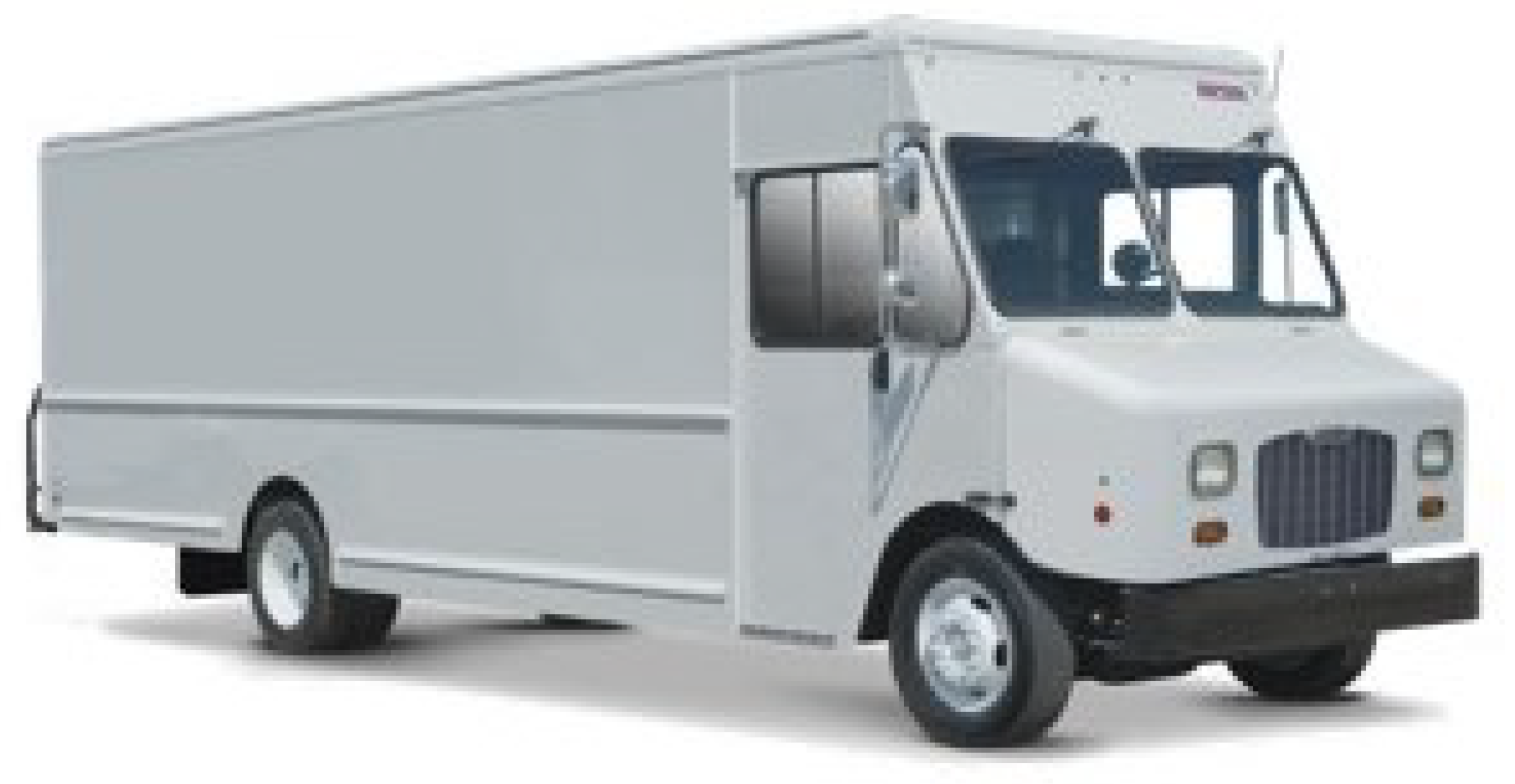
The system studied in this work is a pick-up and delivery (P&D) Class 6 REEV truck, shown in Figure 2. These trucks are typically used by parcel delivery service providers like Amazon and UPS in the United States. The powertrain is designed to meet all the performance requirements of an equivalent conventional (diesel, ICE-powered) truck of the same class. The REEV direct-drive powertrain configuration, as depicted in Figure 3, has a large capacity energy storage system (Battery) and an engine-generator unit (Genset or range-extender), both connected to a DC electric bus that powers the Electric Traction Motor (EM), which finally delivers mechanical power to the wheels. The REEV configuration allows for a significant portion of the energy demand required for traction to be provided by the onboard battery (assumed to be fully charged from the electric grid at the start of the day), whereas the genset is employed as a range-extender unit when the energy stored in the battery is insufficient for fulfilling the powertrain demands.
In this work, the system (i.e., plant) model is developed in MATLAB® R2020b Simulink® 10.2 and dSPACE® R2021-B environments, following the energy-based modeling approach. Based on the energy flow and the constraints associated with every powertrain component, two-vehicle simulators are designed for the REEV delivery truck: the HEV forward simulator for the development of the supervisory controller, and the dynamic programming (DP) backward simulator to calculate the benchmark performance. In the next section, the modeling approach adopted for powertrain components is discussed, followed by the details of the two-vehicle simulators.

2.1. Road Load and Powertrain Components Modeling

Since the focus of this study is on energy consumption, the dynamics of greatest significance are the vehicle road load dynamics in the longitudinal direction, which are given by the first-order differential equation as in Equation (1), considering a lumped inertia consisting of the vehicle mass, M and an equivalent rotational mass due to the inertia of the wheels, I w h e e l s and the wheel radius of gyration, R k , w h e e l s .
M + I w h e e l s R k , w h e e l s 2 d V d t = T a x l e T b r a k e s R w h e e l F l o a d
T a x l e is the axle torque applied on the wheels, and T b r a k e s represents the combined torque due to the mechanical friction (or service) brakes mounted on all the wheels. R w h e e l is the wheel radius. The last term F l o a d is the total resistance acting on the vehicle (aerodynamic drag resistance, rolling resistance, and grade force), as expressed in Equation (2).
F l o a d = 1 2 C d ρ A f V 2 + M g sin ( θ ) + C r M g cos ( θ )
Here, C d is the drag coefficient, ρ is the air density, A f is the frontal area of the vehicle, V is the longitudinal speed of the vehicle, θ is the road grade, g is the gravity constant and C r is the rolling resistance coefficient of the tires. The values of the vehicle parameters that are used in the subsequent simulations are listed in Table 1.
The range-extender consists of a spark-ignition engine coupled with an electric motor/generator, modeled with a constant efficiency of 0.9 to account for the conversion from mechanical to electrical power. The REEV architecture decouples the engine from the wheels, such that the engine speed and torque are independent from the speed and traction request of the vehicle. Therefore, the engine can be operated at maximum efficiency regardless of the vehicle power demand. Connecting the points of maximum efficiency at different powers on the engine map, the optimal operating line (OOL) of the engine has been derived. Finally, assuming that the range-extender will only be operated on the OOL, its performance is characterized by the relationship between generated power and fuel consumption, as depicted in Figure 4 with normalized values.
The electric motor can provide either traction or regenerative braking. The normalized efficiency map, η E M as a function of EM speed, ω E M and EM torque, T E M , is shown in Figure 5. The model relies on the data of a synchronous permanent magnet machine rated at 245 kW peak power.
The battery pack’s nominal voltage is 700 V and the capacity is 74 kWh. The cell chosen for the battery pack is a commercially available NMC cell characterized at The Ohio State University Center for Automotive Research [31]. The battery pack is modeled with a zeroth order equivalent circuit model (ECM), which is sufficient to estimate the State of Charge ( S O C ) dynamics required for the purpose of control-oriented energy consumption modeling. The Kirchhoff equation for the zeroth order ECM can be written as
V t = V o c ( S O C ) I · R 0 ( S O C , T , s i g n ( I ) )
Here, V o c is the open circuit voltage, R 0 is internal resistance in charge and discharge as a function of S O C , cell temperature T, and direction of current. The battery power, P b a t t can be obtained from Equation (3) by multiplying both sides by current I:
P b a t t = I · V o c ( S O C ) I 2 · R 0 ( S O C , T , s i g n ( I ) )
and the resulting quadratic equation given in Equation (4) can be solved univocally for the battery current:
I = V o c ( S O C ) V o c ( S O C ) 2 4 P b a t t R 0 ( S O C , T , s i g n ( I ) ) 2 R 0 ( S O C , T , s i g n ( I ) )
Additionally, current limitations of 2.5C-rate in discharge, I m a x , and 1C-rate in charge, I m i n , are imposed for longevity of the battery pack.
I m i n I I m a x
Finally, the expression for the S O C dynamics is obtained by replacing I from Equation (5) in Equation (7):
d S O C d t = η C I Q b a t t
where the Coulomb efficiency, η C accounts for the losses in the power electronics that are not modeled explicitly, and Q b a t t is the nominal battery capacity. Furthermore, the S O C variation is allowed to be within the hard upper and lower bounds of 100% and 20%, respectively. To maximize the utilization of electrical energy, the battery pack is charged overnight to have maximum S O C at the beginning of the working day, and by the end of the day, it is desired that the S O C reaches the minimum value.
S O C m i n S O C ( t ) S O C m a x S O C ( 0 ) = S O C m a x S O C ( t f ) = S O C m i n
For the REEV, the full torque demand at the wheels, T w , is satisfied by the electric traction motor:
T E M = T w τ d i f f · 1 η d i f f γ
where T E M is the traction motor torque, τ d i f f is the final gear ratio and η d i f f the differential gear efficiency. The exponent γ is 1 in traction ( P E M > 0 ), and –1 during regenerative braking ( P E M < 0 ). The energy management strategy controls the power split between the battery and the range-extender genset:
P b a t t + P g e n s e t = P E M η E M γ + P a u x
P E M is the traction motor power, P a u x is the auxiliary power load and P g e n s e t the genset electric power. During braking, the EM is used as a generator to perform regenerative braking up to a maximal extent of the battery charging limits. Beyond this point, the service brakes are used to fulfill the outstanding braking torque to the wheels.
Finally, the models for the genset emissions and the after-treatment three-way catalytic converter (TWC) are used to determine the amount of nitrogen oxides (NOx) released into the atmosphere by the vehicle.
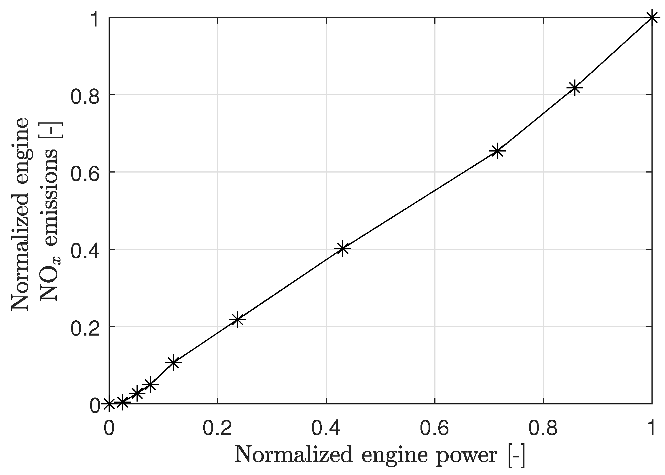
Since engine operation is limited to the operating points specified by the OOL, the engine NOx emissions, m ˙ N O x , e n g , are experimentally obtained for the engine operating points on the OOL as shown in Figure 6.
The exhaust flow is calculated based on the mass flow rate of the charge entering the engine for combustion. It is assumed that the combustion process occurs at the stoichiometric level and A F R = 17.2 is the corresponding air-to-fuel ratio:
m ˙ e x h = m ˙ f + m ˙ a i r = m ˙ f ( 1 + A F R )
The emissions from the genset are treated by the TWC, which oxidizes/reduces the harmful gasses before releasing them from the tailpipe. The conversion efficiency of the TWC changes drastically from 0 to near 100% as the temperature rises above the light-off temperature, T l i g h t o f f , which is defined by 50% TWC conversion efficiency. This behavior is modeled in the simulation by a sigmoid function as given below:
η T W C ( T T W C ) = η T W C , m a x 1 1 + e r ( T T W C T l i g h t o f f )
where the η T W C , m a x is the maximum TWC conversion efficiency, r determines the slope of the curve at T l i g h t o f f , and T T W C is the TWC temperature. Finally, the tailpipe NOx emissions are determined as follows:
m ˙ N O x , t p = m ˙ N O x , e n g ( 1 η T W C ( T T W C ) )
The after-treatment thermal dynamics are modeled to predict the TWC temperature, which greatly impacts the tailpipe emissions. The exhaust temperature out of the engine is simply modeled as a static map and is experimentally obtained for the engine operating points on the OOL as shown in Figure 7.
The temperature of the TWC is considered a lumped quantity and is modeled using the energy balance in Equation (14):
( m c p ) d T T W C d t = h 1 A 1 ( T e x h T T W C ) h 2 A 2 ( T T W C T a m b ) + q ˙ e x h
Here, m c p is the thermal capacity of the TWC, h 1 ( = h 1 ( m ˙ e x h ) ) and h 2 are the convective heat transfer coefficients between exhaust gasses-TWC, and TWC-ambient, respectively. A 1 and A 2 are the areas of the heat transfer surfaces of the TWC. The last term q ˙ e x h represents the exothermic heat release during the catalytic conversion process and is a function of η T W C and m ˙ e x h .

2.2. Backward-Looking Simulator for Dynamic Programming Solution

A backward-looking simulator is used to formulate an optimal control problem and solve it using dynamic programming, a numerical algorithm that assumes complete knowledge of the future driving conditions and returns the globally optimal control policy (power-split) that minimizes fuel consumption. The flow of information in the backward-looking simulator is illustrated in the block diagram in Figure 8. The vehicle speed defined by the drive cycle, which is assumed to be known, is the input. From the drive cycle, the total torque and corresponding power request required at the wheels are calculated. This information is then passed downstream to the energy management system, with adjustments made based on the components’ efficiency and gear ratio. The DP algorithm is subsequently used to determine the optimal power split for each time instant depending on the system states.

2.3. Forward-Looking Simulator for Online Control Implementation

The forward-looking simulator, as illustrated by the block diagram in Figure 9, is modeled in the Simulink virtual environment for the development of the supervisory controller. The driver model generates the accelerator and the brake pedal position requests based on the difference between the drive cycle-specific reference speed and the current vehicle speed. The pedal positions are converted into powertrain commands by the supervisory controller, and passed on to the various powertrain components. The powertrain responds to these commands and generates the torque at the wheels, producing traction or braking. Based on the wheel torque command, the corresponding power request is calculated and split between the genset and the battery by the energy management strategy in the supervisory controller. The plant (vehicle) and controller are developed in the MATLAB/Simulink environment and are used in MIL simulations for designing and testing the energy management strategy.
The forward-looking simulator is also utilized in the HIL simulation to validate the real-time implementation of the proposed control strategy. The details of the HIL setup are provided in the next section.

2.4. Hardware-in-the-Loop Simulation Setup

The HIL setup is used for validation of the online implementation of the energy management strategies. The schematic of transitioning from the MIL to HIL simulation setup is shown in Figure 10 with the component description of the HIL setup provided in Table 2.
A Speedgoat Baseline Real-Time Target Machine and a dSPACE Midsize HIL simulator are utilized for the real-time execution of the controller and plant model, respectively. Both hardware components are equipped with CAN channels for communication. The details of the control strategy developed and tested in the controller, such as the energy management strategy, will be discussed later. The Simulink model used in the MIL simulation is divided into two separate files for the plant and controller models. To facilitate signal transmission through CAN communication, the dSPACE proprietary RTICAN, and Simulink Real-Time: Speedgoat I/O blocksets are integrated into the plant and controller models, respectively. The signals virtually exchanged between the plant and controller in MIL are transmitted according to CAN communication protocols using these blocksets. Finally, the Simulink Coder automatically generates standalone C code for these models, enabling deployment of the plant and the controller on the corresponding hardware.

2.5. Representative Pick-Up and Delivery Drive Cycle Description

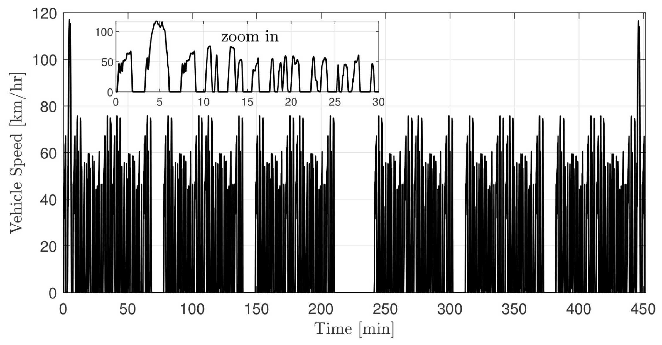
The performance of the REEV simulator is evaluated using a specific driving cycle, illustrated in Figure 11. To generate a representative pick-up and delivery daily duty-cycle (approximately 8 h) in an urban environment, 12 repetitions of the Federal Urban Driving Schedule (FUDS) have been assembled in a sequence, including delivery stops. The zoomed-in view in Figure 11 shows a single instance of the FUDS speed trace. During longer stops, such as the lunch break between 210 and 240 min and intermediate breaks of 15 min after every two repetitions of the FUDS drive cycle, the vehicle is turned off to save fuel and battery energy. The relevant statistical features of the drive cycle are summarized in Table 3.

3. Optimal Energy Management Strategy Using Dynamic Programming

The Dynamic Programming function developed in MATLAB® by [32] is utilized in this work to derive the globally optimal energy management strategy for the REEV. The optimization problem is formulated as a constrained optimal control problem as in the following Equation (15):
[ P g e n * , u g e n * ] = arg   min c y c l e m ˙ f ( P g e n ) d t + Φ | Δ u g e n | subject to: P b a t t ( t ) + P g e n ( t ) = P E M , e l e c ( t ) + P a c c ( t ) T E M , m i n , c o n t ( ω E M ( t ) ) T E M ( t ) T E M , m a x , c o n t ( ω E M ( t ) ) d S O C ( t ) d t = η C I ( t ) Q b a t t S O C m i n S O C S O C m a x S O C ( 0 ) = S O C m a x S O C ( t f ) = S O C m i n I m i n I ( t ) I m a x d T T W C ( t ) d t = 1 m c p [ h 1 A 1 ( T e x h ( t ) T T W C ( t ) ) h 2 A 2 ( T T W C ( t ) T a m b ) + q ˙ e x h ( t ) ] T T W C ( 0 ) = T a m b
The states of the system are the battery state of charge, S O C , the genset on-off status, x g e n , and the temperature of the TWC, T T W C . The control inputs are the genset state control, u g e n , and the genset power level, P g e n . Φ is a penalty term on the range-extender start-stops ( | Δ u g e n | ). The cost function not only includes fuel consumption (see c y c l e m ˙ f ( P g e n ) d t in Equation (15)) as the optimization objective, but also the frequency of genset start-stops (see Φ | Δ u g e n | in Equation (15)). Reducing start-stops is expected to enhance component durability, reduce NOx emissions, and improve driver comfort. Moreover, it is found that explicitly incorporating emissions into the cost function does not provide any additional benefits, as the tailpipe NOx emissions are implicitly kept below the prescribed regulatory limits (0.2 g/bhp-h) for a Class 6 vehicle by controlling the start-stops. Nevertheless, following 2027, regulations will become significantly more stringent, with the limit reduced to 0.05 g/bhp-h, making it essential to include emissions directly in the cost function [33]. For further details on how emissions can be incorporated into the cost function, readers are encouraged to refer to previous work [34]. The model used for system dynamics is the backward-looking model, which considers a priori knowledge of vehicle speed as well as perfect speed tracking by the vehicle. The optimal energy management results obtained with DP form the benchmark solutions for the development of the onboard implementable energy management strategy, the details of which are provided in the next section.

4. Online Implementable Energy Management Strategies

This section describes two different strategies for energy management. First, a simple baseline heuristic-based charge-depleting–charge-sustaining (CD–CS) strategy, widely utilized for plug-in hybrid electric vehicles, is explained. This is followed by a description of the proposed Hierarchical Energy Management Strategy (H–EMS) for REEV.

4.1. Charge-Depleting–Charge-Sustaining Strategy

The implementation of the CD–CS strategy is straightforward, as it does not rely on any information from the drive cycle or the vehicle powertrain, other than the battery state of charge [35,36,37]. Initially, the powertrain operates in pure electric mode, discharging the battery from a high initial S O C until a lower threshold (20%) is reached (charge-depleting mode). After this, the genset starts to turn on and off based on a simple thermostatic controller, and the vehicle operates in hybrid mode (charge-sustaining mode), maintaining the S O C within a prescribed admissible range. When the S O C reaches the lower bound of this range, the genset is activated and operates at the highest efficiency point of the operating line that satisfies the power requested at the wheels, also considering the battery power limits imposed by the battery management system (BMS). The genset is turned off when the S O C reaches the upper bound of the admissible range.

4.2. Hierarchical Energy Management Strategy

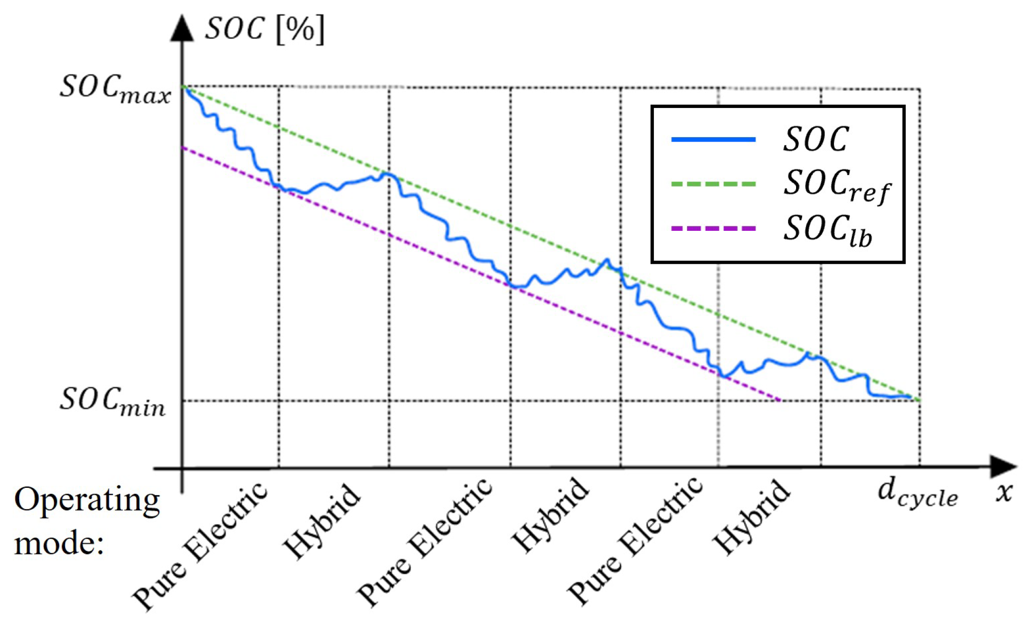
The H–EMS is a multi-level decision-making process in which the higher-level controller dictates the actions of the subordinate controllers. The H–EMS controller proposed in this study is a development of the energy management strategy designed in our prior research [17]. The hierarchical controller consists of a two-level architecture: a rule-based controller at the higher level and a sub-optimal EMS called the Equivalent Consumption Minimization Strategy (ECMS) at the lower level. The rule-based strategy at the higher level acts as a supervisory controller that decides the mode of operation of the REEV: whether to operate in pure electric mode (using only the battery) or in hybrid mode (using a combination of the battery and the genset). This decision determines when to start and stop the genset and is based on a reference battery S O C . A reference S O C ( S O C r e f ) that linearly depletes the energy within the battery with distance is generated based on the intended travel distance ( d c y c l e ), starting from full S O C ( S O C m a x ) and terminating at the desired final S O C ( S O C m i n ):
S O C r e f ( t ) = S O C m a x S O C m a x S O C m i n d c y c l e x v e h ( t )
Delivery vehicles typically have a predetermined route provided at the start of the day, allowing for the calculation of the total expected driving distance and enabling the creation of this reference tracking profile. This S O C reference is inspired by the results of previous works demonstrating the optimality of a blended energy management strategy for REEVs, as discussed in the Introduction and further validated in this study with DP simulations, as shown in the following.
The rule-based controller tracks the battery S O C while allowing it to deviate from the reference S O C profile down to a lower bound ( S O C l b ). The depiction of the H-EMS higher-level controller decision-making process of operating the REEV powertrain in either pure electric or hybrid mode is shown in Figure 12.
For the duration for which the REEV operates in pure electric mode, the genset remains off. When the S O C falls below the lower bound, the genset is activated, and the operation mode shifts to hybrid, where both the battery and the genset share the driver’s power requests. The genset continues to operate until the S O C returns to the reference value. The lower bound is defined as the reference S O C with an offset of the S O C lower bound threshold ( S O C l b , t h r e s h o l d ), a calibration parameter that significantly affects the frequency of genset start-stop events:
S O C l b = S O C r e f S O C l b , t h r e s h o l d
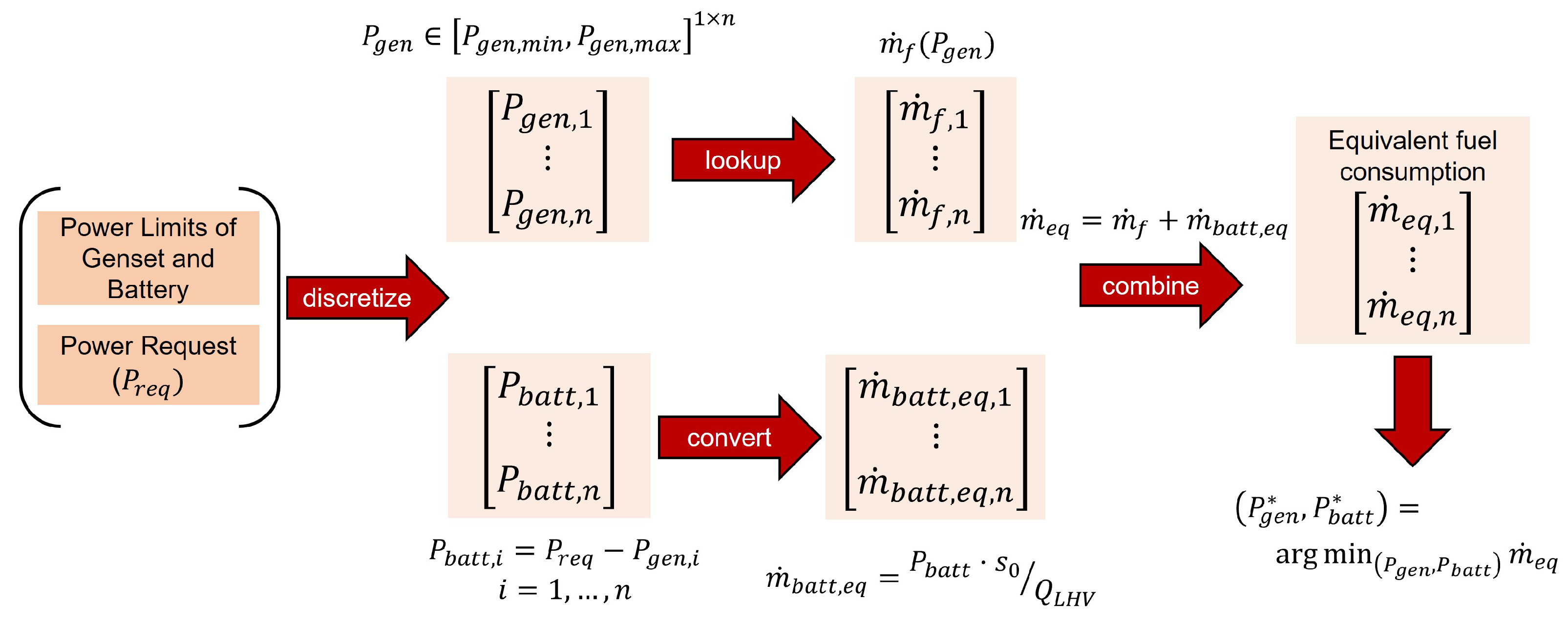
The lower-level controller manages the powertrain components and involves the decision process of splitting the total electric motor power request between the battery and the genset. The battery supplies all required power during the all-electric mode. However, ECMS is employed during hybrid mode to make power split decisions. ECMS determines the combination of genset and battery power that minimizes instantaneous equivalent fuel consumption. To calculate the equivalent fuel consumption for the battery, m ˙ b a t t , e q , the battery power request is normalized by the lower heating value of the fuel ( Q L H V ) and multiplied by an equivalence factor, s 0 . The combination of genset and battery power that results in the least equivalent fuel consumption is sent as power requests to the corresponding powertrain components. The flowchart detailing the implementation of ECMS is illustrated in Figure 13. For a more detailed understanding of ECMS, readers are encouraged to consult references [19,38,39].

5. Results and Discussion

The results of the DP simulations are first presented in this section, as they provide a guideline and a benchmark for the development of the H-EMS. Then the results for the H-EMS are presented both in MIL and HIL environments and compared.

5.1. Dynamic Programming Simulation Results

DP provides the globally optimal solution for minimizing the objective function. However, to understand the effect of the genset start-stop penalty ( Φ ) on the optimal solution, a parameter study is conducted. It is worth noting that limiting the number of genset start-stops has a positive impact by reducing engine wear, improving drive quality, and limiting emissions as the cold starts are reduced. The number of genset starts and the fuel consumption for different values of Φ are shown in Figure 14. The values are tabulated in Table 4.
It can be observed that there is an inverse relationship between genset starts and fuel consumption. As the fuel penalty increases, the number of genset starts decreases, but this comes at the cost of higher fuel consumption. Moreover, significantly increasing the fuel penalty results in longer intervals between stops, which will lead to a cold start when the genset is used again. For optimal fuel consumption, the scenario without start-stop penalty yields the best result, using only 14.5 kg of fuel, but this comes with 546 genset start-stops. The optimal solution is achieved with a 20 g genset start-stop penalty, providing the best overall outcome with 15.7 kg of fuel consumption, 23 genset start-stops (only one of which is a cold start), and just 0.08 g/bhp-hr of NOx emissions, well below regulatory limits. This result serves as the benchmark for the online implementable EMS.

5.2. Model-in-the-Loop Simulation Results

MIL simulation results were obtained for the two online implementable energy management strategies, CD–CS and H–EMS. These results were then compared against the DP benchmark strategy, as shown in Table 5. The proposed H–EMS strategy provides a 7% reduction in fuel consumption over the baseline CD–CS strategy, while the maximum possible reduction, as indicated by the DP benchmark, is 8.7%. H–EMS performs near-optimally in terms of fuel consumption and emissions. Additionally, regarding genset start-stops, H–EMS outperforms the DP benchmark by having four fewer starts.
Figure 15 shows S O C trajectories and the genset ‘on’ periods obtained from the simulation results of the two online implementable control strategies in the forward simulator, alongside benchmark results from the DP backward simulator. Notable differences exist between the trajectories, which directly stem from how the operation of the range-extender genset is integrated with the battery to provide the necessary power to the EM.
It is interesting to observe that with H–EMS, the S O C trajectory exhibits a behavior that is closer to the DP optimal solution, particularly in terms of periodically operating the vehicle in hybrid mode and allowing the genset to charge the battery pack during this operation, thus achieving a blended EMS. In the case of DP, having complete knowledge of the drive cycle beforehand enables strategic operation of the genset, optimizing the trade-off between fuel consumption and genset start-stops. However, this optimization is not guaranteed with H–EMS, as only the total driving distance is known, leading to sub-optimal fuel consumption results compared to DP.
Finally, the Sankey diagram of the energy flow in the powertrain is illustrated in Figure 16. The energy required to overcome the road load (158.4 MJ) remains consistent across all simulations. However, the energy split at the source varies depending on the EMS employed. In the CD−CS strategy, the genset is primarily used for load-following during the charge-sustaining portion and for battery charging whenever possible. This load-following operation prevents the genset from consistently operating at its highest efficiency, resulting in the highest total electrical energy consumption from the genset, amounting to 314.5 MJ. In contrast, the genset in the DP benchmark and H–EMS strategies provides less electrical energy (283 MJ, approximately the same amount in the two cases), which is about 60% of the total, with the remainder supplied by the battery. Another important observation concerns the energy lost during braking, represented as brake losses in the Sankey diagram: the DP benchmark EMS maximizes kinetic energy recovery through regenerative braking, resulting in the least brake energy loss of only 111.6 MJ, and the H–EMS strategy has slightly higher brake energy losses, totaling about 118.7 MJ.

5.3. Hardware-in-the-Loop Simulation Results

The results presented in the previous section show that the H–EMS strategy provides near-optimal performance in the MIL simulations. To evaluate the deployment of the strategy in a controller for real-time implementation, HIL simulations were conducted. The controller is separated from the plant and deployed on an embedded target machine (Speedgoat real-time target machine), while the plant model runs on a real-time simulator (dSPACE mid-size HIL simulator), as explained earlier in the HIL setup. The plant emulates the actual vehicle’s behavior by generating sensor output signals for the controller and providing appropriate responses to the controller’s actions. The automatically generated C−code for the controller is first tested through SIL and PIL simulation steps to verify the proper execution of the compiled controller code before deployment in HIL testing.
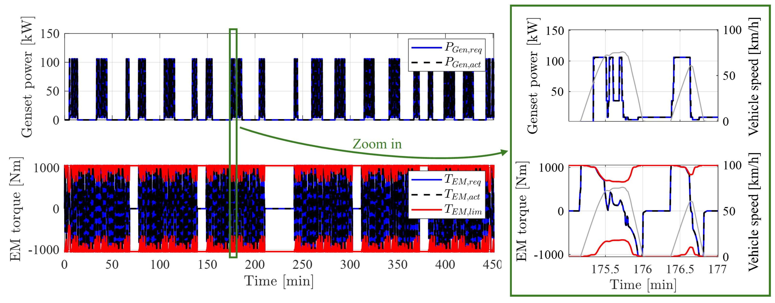
To maintain consistency with the MIL simulations, the controller’s decision-making frequency is kept the same, operating at a 100 ms time step, while the plant is updated at a much higher rate of 5 ms. A zero-order hold is applied to the controller signal to manage the discrepancy between the time steps of the controller and the plant. Additionally, the signals exchanged between the plant and controller are communicated via CAN communication protocols, which require signal quantization. The powertrain operation in terms of genset power and EM torque as obtained during the HIL simulation of H–EMS controller is shown in Figure 17. It can be observed that the plant provides the genset power and EM torque requested by the H–EMS controller. In addition, H–EMS ensures that the EM torque is always within the continuous torque limits. Moreover, when the vehicle is stationary, the genset continues to operate at a lower power to recharge the battery.
The simulation results in terms of fuel consumption, genset starts-stops, and emissions obtained in HIL simulation, along with a comparison to the results of the MIL simulation for the H–EMS strategy, are presented in Table 6. The fuel consumption calculated in the HIL simulation is 16.3 kg, which is only 1.8% higher than that in the MIL simulation, while the number of genset starts and NOx emissions remain the same. The difference in fuel consumption is an artifact of running the plant model in the HIL simulation at a different simulation timestep compared to the MIL simulation.
Finally, the S O C trajectory obtained from the HIL simulation is plotted against the one from the MIL simulation in Figure 18. Both S O C profiles are similar, indicating that the performance of H–EMS in the MIL simulation closely matches that of the real-time HIL simulation. The minor differences observed can be attributed to the slightly different genset operation in MIL and HIL simulations and the mismatch in power requested from the battery due to the quantization step during the signal communication between the plant and the controller in the HIL simulation.

6. Conclusions

This work presented the development, testing, and validation of a proposed H–EMS controller designed for energy management in a medium-duty Class 6 range-extended electric vehicle for pick-up and delivery applications. The controller’s performance was verified against two different EMS: a baseline CD–CS strategy and a benchmark EMS obtained using dynamic programming, a global optimization technique. The simulation results from the MIL simulations demonstrated the effectiveness of the proposed H–EMS, achieving near-optimal fuel consumption with approximately a 7% reduction compared to the baseline, while providing comparable emissions and genset starts to the benchmark. Finally, the HIL simulation showcased the real-time implementation capabilities of the H–EMS for deployment in vehicles. Further improvements to the H–EMS controller are anticipated by enhancing kinetic energy recovery during braking events and incorporating emissions directly into the problem formulation to comply with upcoming stringent N O x emissions regulations for medium- and heavy-duty engines.

Author Contributions

Conceptualization, A.S. and G.R.; methodology, A.S. and M.V.; software, A.S.; validation, A.S.; formal analysis, A.S.; investigation, A.S.; data curation, A.S.; writing—original draft preparation, A.S. and M.V.; writing—review and editing, M.V.; visualization, A.S.; supervision, G.R.; project administration, G.R.; funding acquisition, G.R. All authors have read and agreed to the published version of the manuscript.

Funding

This research was funded by the United States Department of Energy: U.S.-China Clean Energy Research Center (CERC) Truck Research Utilizing Collaborative Knowledge (TRUCK) Program.

Data Availability Statement

The original contributions presented in the study are included in the article, further inquiries can be directed to the corresponding author.

Acknowledgments

We are grateful to the U.S. Department of Energy for its overall sponsorship of the CERC program, to Argonne National Laboratory, for leading the CERC TRUCK program, and to technical partners Cummins Inc. and Freightliner Custom Chassis Corporation for their invaluable guidance and support during the project. The views expressed herein do not necessarily represent the views of the U.S. Department of Energy or the United States Government.

Conflicts of Interest

The authors declare no conflicts of interest.

References

  1. Delgado, O.; Rodríguez, F. CO2 Emissions and Fuel Consumption Standards for Heavy-Duty Vehicles in the European Union-International Council on Clean Transportation. 2018. Available online: https://trid.trb.org/View/1513348 (accessed on 15 July 2024).
  2. Rizzoni, G.; Ahmed, Q.; Arasu, M.; Oruganti, P.S. Transformational Technologies Reshaping Transportation—An Academia Perspective (L. Ray Buckendale 2019 Lecture); SAE Technical Paper 2019-01-2620; SAE International: Warrendale, PA, USA, 2019. [Google Scholar] [CrossRef]
  3. Alternative Fuels Data Center: Hybrid Electric Vehicles. Available online: https://afdc.energy.gov/vehicles/electric-basics-hev (accessed on 15 July 2024).
  4. Nykvist, B.R.; Olsson, O. The feasibility of heavy battery electric trucks. Joule 2021, 5, 901–913. [Google Scholar] [CrossRef]
  5. Sugihara, C.; Hardman, S.; Kurani, K. Social, technological, and economic barriers to heavy-duty truck electrification. Res. Transp. Bus. Manag. 2023, 51, 101064. [Google Scholar] [CrossRef]
  6. Cunanan, C.; Tran, M.K.; Lee, Y.; Kwok, S.; Leung, V.; Fowler, M. A Review of Heavy-Duty Vehicle Powertrain Technologies: Diesel Engine Vehicles, Battery Electric Vehicles, and Hydrogen Fuel Cell Electric Vehicles. Clean Technol. 2021, 3, 474–489. [Google Scholar] [CrossRef]
  7. Impullitti, J.; Kosowski, M. Plug-In Hybrid Medium-Duty Truck Demonstration and Evaluation Prepared for: California Energy Commission; South Coast Air Quality Management District: Diamond Bar, CA, USA, 2020.
  8. Moriarty, K. Clean Cities Guide to Alternative Fuel and Advanced Medium-and Heavy-Duty Vehicles; National Renewable Energy Lab. (NREL): Golden, CO, USA, 2013.
  9. Xiao, B.; Ruan, J.; Yang, W.; Walker, P.D.; Zhang, N. A review of pivotal energy management strategies for extended range electric vehicles. Renew. Sustain. Energy Rev. 2021, 149, 111194. [Google Scholar] [CrossRef]
  10. Zhao, T.; Ahmed, Q.; Rizzoni, G. Influence of Battery Charging Current Limit on the Design of Range Extender Hybrid Electric Trucks. In Proceedings of the 2018 IEEE Vehicle Power and Propulsion Conference (VPPC), Chicago, IL, USA, 27–30 August 2018; pp. 1–6. [Google Scholar] [CrossRef]
  11. Duran, A.; Li, K.; Kresse, J.; Kelly, K. Development of 80- and 100- Mile Work Day Cycles Representative of Commercial Pickup and Delivery Operation; SAE Technical Papers; National Renewable Energy Lab. (NREL): Golden, CO, USA, 2018; pp. 10–12. [CrossRef]
  12. Yang, C.; Sun, T.; Wang, W.; Li, Y.; Zhang, Y.; Zha, M. Regenerative braking system development and perspectives for electric vehicles: An overview. Renew. Sustain. Energy Rev. 2024, 198, 114389. [Google Scholar] [CrossRef]
  13. Hunter, C.; Penev, M.; Reznicek, E.; Lustbader, J.; Birky, A.; Zhang, C. Spatial and Temporal Analysis of the Total Cost of Ownership for Class 8 Tractors and Class 4 Parcel Delivery Trucks; National Renewable Energy Lab. (NREL): Golden, CO, USA, 2018.
  14. Tran, D.D.; Vafaeipour, M.; Baghdadi, M.E.; Barrero, R.; Mierlo, J.V.; Hegazy, O. Thorough state-of-the-art analysis of electric and hybrid vehicle powertrains: Topologies and integrated energy management strategies. Renew. Sustain. Energy Rev. 2020, 119, 109596. [Google Scholar] [CrossRef]
  15. Panday, A.; Bansal, H.O. A review of optimal energy management strategies for hybrid electric vehicle. Int. J. Veh. Technol. 2014, 2014, 160510. [Google Scholar] [CrossRef]
  16. Zhu, Y.; Li, X.; Liu, Q.; Li, S.; Xu, Y. Review article: A comprehensive review of energy management strategies for hybrid electric vehicles. Mech. Sci. 2022, 13, 147–188. [Google Scholar] [CrossRef]
  17. Villani, M.; Shiledar, A.; Ahmed, Q.; Rizzoni, G. Design of a Hierarchical Energy Management Strategy for a Range-Extender Electric Delivery Truck. In Proceedings of the 2021 European Control Conference, ECC 2021, Delft, The Netherlands, 29 June 2021–2 July 2021; Institute of Electrical and Electronics Engineers Inc.: Piscataway, NJ, USA, 2021; pp. 892–898. [Google Scholar] [CrossRef]
  18. Bellman, R. Dynamic Programming and Lagrange Multipliers. Proc. Natl. Acad. Sci. USA 1956, 42, 767–769. [Google Scholar] [CrossRef]
  19. Paganelli, G.; Guerra, T.M.; Delprat, S.; Santin, J.J.; Delhom, M.; Combes, E. Simulation and assessment of power control strategies for a parallel hybrid car. Proc. Inst. Mech. Eng. Part D J. Automob. Eng. 2000, 214, 705–717. [Google Scholar] [CrossRef]
  20. Stockar, S.; Marano, V.; Canova, M.; Rizzoni, G.; Guzzella, L. Energy-optimal control of plug-in hybrid electric vehicles for real-world driving cycles. IEEE Trans. Veh. Technol. 2011, 60, 2949–2962. [Google Scholar] [CrossRef]
  21. Tribioli, L.; Barbieri, M.; Capata, R.; Sciubba, E.; Jannelli, E.; Bella, G. A real time energy management strategy for plug-in hybrid electric vehicles based on optimal control theory. Energy Procedia 2014, 45, 949–958. [Google Scholar] [CrossRef]
  22. Padmarajan, B.V.; McGordon, A.; Jennings, P.A. Blended Rule-Based Energy Management for PHEV: System Structure and Strategy. IEEE Trans. Veh. Technol. 2016, 65, 8757–8762. [Google Scholar] [CrossRef]
  23. Lei, Z.; Qin, D.; Zhao, P.; Li, J.; Liu, Y.; Chen, Z. A real-time blended energy management strategy of plug-in hybrid electric vehicles considering driving conditions. J. Clean. Prod. 2020, 252, 119735. [Google Scholar] [CrossRef]
  24. Yao, D.; Lu, X.; Chao, X.; Zhang, Y.; Shen, J.; Zeng, F.; Zhang, Z.; Wu, F. Adaptive Equivalent Fuel Consumption Minimization Based Energy Management Strategy for Extended-Range Electric Vehicle. Sustainability 2023, 15, 4607. [Google Scholar] [CrossRef]
  25. Xi, L.; Zhang, X.; Sun, C.; Wang, Z.; Hou, X.; Zhang, J. Intelligent Energy Management Control for Extended Range Electric Vehicles Based on Dynamic Programming and Neural Network. Energies 2017, 10, 1871. [Google Scholar] [CrossRef]
  26. Lin, W.; Zhao, H.; Zhang, B.; Wang, Y.; Xiao, Y.; Xu, K.; Zhao, R.; Lin, W.; Zhao, H.; Zhang, B.; et al. Predictive Energy Management Predictive Energy Management Strategy for Range-Extended Electric Vehicles Based on ITS Information and Start-Stop Optimization with Vehicle Velocity Forecast. Energies 2022, 15, 7774. [Google Scholar] [CrossRef]
  27. Llorente, R.M. Embedded Control System Development Process: Model-Based Design and Architecture Basics. In Practical Control of Electric Machines: Model-Based Design and Simulation; Advances in Industrial Control; Springer: Berlin/Heidelberg, Germany, 2020; pp. 1–26. [Google Scholar] [CrossRef]
  28. Board, T.R.; Council, N.R. Technologies and Approaches to Reducing the Fuel Consumption of Medium- and Heavy-Duty Vehicles; National Academies Press: Washington, DC, USA, 2010; pp. 1–250. [Google Scholar] [CrossRef]
  29. Shokry, H.; Hinchey, M. Model-based verification of embedded software. Computer 2009, 42, 53–59. [Google Scholar] [CrossRef]
  30. Krizan, J.; Ertl, L.; Bradac, M.; Jasansky, M.; Andreev, A. Automatic code generation from Matlab/Simulink for critical applications. In Proceedings of the Canadian Conference on Electrical and Computer Engineering, Toronto, ON, Canada, 4–7 May 2014; Institute of Electrical and Electronics Engineers Inc.: Piscataway, NJ, USA, 2014. [Google Scholar] [CrossRef]
  31. Villani, M.; Shiledar, A.; D’Arpino, M.; Rizzoni, G. Battery Selection and Optimal Energy Management for a Range-Extended Electric Delivery Truck. SAE Int. J. Adv. Curr. Pract. Mobil. 2022, 5, 1282–1291. [Google Scholar] [CrossRef]
  32. Sundström, O.; Guzzella, L. A generic dynamic programming Matlab function. In Proceedings of the IEEE International Conference on Control Applications, St. Petersburg, Russia, 8–10 July 2009; pp. 1625–1630. [Google Scholar] [CrossRef]
  33. International Council on Clean Transportation. U.S. Heavy-Duty Vehicle NOx Standards: Updates to Emission Limits, Testing Requirements, and Compliance Procedures; International Council on Clean Transportation: San Francisco, CA, USA, 2023. [Google Scholar]
  34. Villani, M.; Shiledar, A.; Zhao, T.; Lana, C.; Le, D.; Ahmed, Q.; Rizzoni, G. Optimal Energy Management Strategy for Energy Efficiency Improvement and Pollutant Emissions Mitigation in a Range-Extender Electric Vehicle. In Proceedings of the 15th International Conference on Engines & Vehicles, Capri, Italy, 12–16 September 2021. [Google Scholar] [CrossRef]
  35. Gonder, J.; Markel, T. Energy management strategies for plug-in hybrid electric vehicles. In Proceedings of the SAE World Congress & Exhibition, Detroit, MI, USA, 16–19 April 2007. [Google Scholar] [CrossRef]
  36. Jeffers, M.A.; Miller, E.; Kelly, K.; Kresse, J.; Li, K.; Dalton, J.; Kader, M.; Frazier, C. Development and Demonstration of a Class 6 Range-Extended Electric Vehicle for Commercial Pickup and Delivery Operation. In Proceedings of the WCX 2020 World Congress Experience, Detroit, MC, USA, 21–23 April 2020; pp. 1–7. [Google Scholar] [CrossRef]
  37. Rodrigues, M.; King, S.; Scott, D.; Wang, D. Advanced energy management strategies for range extended electric vehicle. In Proceedings of the Symposium on International Automotive Technology 2015, Pune, India, 21–24 January 2015. [Google Scholar] [CrossRef]
  38. Paganelli, G.; Delprat, S.; Guerra, T.M.; Rimaux, J.; Santin, J.J. Equivalent consumption minimization strategy for parallel hybrid powertrains. IEEE Veh. Technol. Conf. 2002, 4, 2076–2081. [Google Scholar] [CrossRef]
  39. Sciarretta, A.; Back, M.; Guzzella, L. Optimal control of parallel hybrid electric vehicles. IEEE Trans. Control. Syst. Technol. 2004, 12, 352–363. [Google Scholar] [CrossRef]
Figure 1. Various simulation stages of the model-based design for the controller development: (a) Model-In-The-Loop simulation. (b) Software-In-The-Loop simulation. (c) Processor-In-The-Loop simulation. (d) Hardware-In-The-Loop simulation.
Energies 17 05294 g001
Figure 2. Class 6 pick-up and delivery truck.
Energies 17 05294 g002
Figure 3. Direct drive powertrain architecture (the EM is directly connected to the Axle without a transmission). The arrows represent the allowed direction of the energy flow through the REEV powertrain.
Energies 17 05294 g003
Figure 4. Range-extender optimal operating line: fuel consumption vs electrical power.
Energies 17 05294 g004
Figure 5. Electric motor normalized efficiency map.
Energies 17 05294 g005
Figure 6. Normalized NOx engine emissions.
Energies 17 05294 g006
Figure 7. Engine exhaust temperature.
Energies 17 05294 g007
Figure 8. Block diagram of the backward simulator showing the information flow.
Energies 17 05294 g008
Figure 9. Block diagram of the forward simulator showing the information flow.
Energies 17 05294 g009
Figure 10. Transitioning from MIL simulation framework in MATLAB/Simulink to HIL simulation using dSPACE and Speedgoat setup.
Energies 17 05294 g010
Figure 11. Representative pick-up and delivery (P&D) drive cycle. (Zoom-in insert shows one instance of the FUDS cycle).
Energies 17 05294 g011
Figure 12. Depiction of H–EMS higher-level decision-making process of operating the powertrain in pure electric or hybrid mode.
Energies 17 05294 g012
Figure 13. ECMS controller implementation for REEV. The equivalent fuel consumption is calculated for the combinations of genset and battery powers that satisfy the total power request. The genset and battery powers that provide the minimum equivalent fuel consumption are the best solution.
Energies 17 05294 g013
Figure 14. Number of genset starts and fuel consumption generated by successively increasing the genset start-stops penalty parameter. Values in the brackets are the fuel penalty (in g) for the genset start followed by the number of cold starts.
Energies 17 05294 g014
Figure 15. Comparison of S O C trajectories (top) and genset ‘on’ period (bottom) for CD–CS (baseline), DP (benchmark), and H–EMS energy management strategies.
Energies 17 05294 g015
Figure 16. Sankey diagram for comparing energy flows in CD–CS (baseline), DP (benchmark) and H–EMS energy management strategies.
Energies 17 05294 g016
Figure 17. Range-extender (top) and EM (bottom) operation in HIL simulation using the H–EMS strategy. The zoomed-in view on the right shows a detail in a two-minute window.
Energies 17 05294 g017
Figure 18. Comparison of S O C trajectories obtained using H-EMS strategy along with genset ‘on’ period in MIL and HIL simulations.
Energies 17 05294 g018
Table 1. Class 6 vehicle and powertrain specification.
ParameterValue
Mass [kg]8890
Rolling resistance coefficient [-]0.0072
Wheel radius [m]0.4191
Frontal area [m2]5.41
Aerodynamic drag coefficient [-]0.622
Genset peak power [kW]148.5
Electric motor peak power [kW]245
Battery pack energy [kWh]74
Table 2. HIL setup component description.
Software/HardwareDescription
MATLAB® R2020b/Simulink® 10.2Automatic C code generation
Post-processing of HIL results
dSPACE® ControlDesk R2021-BTo set up and monitor the real-time HIL experiment
dSPACE® Scalexio Midsize HIL systemDS1006 processor board for running complex plant model
DS2211 HIL I/O board for CAN communication
SpeedGoat® Real-time Target Machine BaselineTarget machine for controller code execution
IO613 board for CAN communication
Communication ProtocolsHigh-speed CAN
Custom database file for CAN messages
Baud Rate 500 Kbit/s
Table 3. Drive cycle statistics.
ParameterValue
Duration450 min
Distance covered148 km
Maximum speed116 km/h
Average speed40 km/h
Maximum acc.1.15 m/s2
Maximum decel.1.90 m/s2
Table 4. Genset start-stop penalty parametric study results.
Fuel Penalty [g]Fuel Used [kg]Genset Starts [-]Emissions [g/bhp-h]
014.55460.08
514.81210.08
1015.3500.08
2015.7230.08
3016.0110.12
4016.0100.12
5016.180.13
Table 5. Comparison of MIL simulation results with DP benchmark.
EMSFuel Consumption [kg] (Improvement over Baseline)Genset Starts [-]Emissions [g/bhp-h]
CD–CS (baseline, MIL)17.2210.08
DP (benchmark)15.7 (−8.7%)230.08
H–EMS (MIL)16.0 (−7.0%)190.08
Table 6. Comparison of MIL and HIL simulation for H-EMS strategy.
EMSFuel Consumption [kg]Genset Starts [-]Emissions [g/bhp-h]
H–EMS (MIL)16.0190.08
H–EMS (HIL)16.3 (+1.8%)190.08
Disclaimer/Publisher’s Note: The statements, opinions and data contained in all publications are solely those of the individual author(s) and contributor(s) and not of MDPI and/or the editor(s). MDPI and/or the editor(s) disclaim responsibility for any injury to people or property resulting from any ideas, methods, instructions or products referred to in the content.