Article

Phase Behavior and Rational Development Mode of a Fractured Gas Condensate Reservoir with High Pressure and Temperature: A Case Study of the Bozi 3 Block

1
Tarim Oilfield Company, PetroChina, Korla 841000, China
2
College of Information and Control, China University of Petroleum, Beijing 102249, China
3
China United Coalbed Methane Co., Ltd., Taiyuan 030000, China
4
Research Institute of Oil Exploration and Development, Liaohe Oilfield of PetroChina, Panjin 124010, China
*
Author to whom correspondence should be addressed.
Energies 2024, 17(21), 5367; https://doi.org/10.3390/en17215367
Submission received: 25 September 2024 / Revised: 23 October 2024 / Accepted: 26 October 2024 / Published: 28 October 2024

Abstract

:
The Bozi 3 reservoir is an ultra-deep condensate reservoir (−7800 m) with a high temperature (138.24 °C) and high pressure (104.78 MPa), leading to complex phase behaviors. Few PVT studies could be referred in the literature to meet such high temperature and pressure conditions. Furthermore, it is questionable regarding the applicability of existing condensate production techniques to such a high temperature and pressure reservoir. This study first characterized the phase behavior via PVT experiments and EOS tuning. The operating conditions were then optimized through reservoir numerical simulation. Results showed that: (1) the critical condensate temperature and pressure of Bozi 3 condensate gas were 326.24 °C and 43.83 MPa, respectively; (2) four gases (methane, recycled dry gas, carbon dioxide, and nitrogen) were analyzed, and methane was identified as the optimal injection gas; (3) gas injection started when the production began to fall and achieved higher recovery than gas injection started when the pressure fell below the dew-point pressure; (4) simultaneous injection of methane at both the upper and lower parts of the reservoir can effectively produce condensate oil over the entire block. This scheme achieved 8690.43 m3 more oil production and 2.75% higher recovery factor in comparison with depletion production.

1. Introduction

Different to conventional oil and gas reservoirs, a condensate gas reservoir has their dual properties, as well as complex phase behavior [1]. During the production process, as pressure drops below the dew-point pressure, the heavier components fall out in the reservoir as liquid accumulates in large quantities near the wellbore, blocking the pore space and reducing the gas phase permeability [2]. Therefore, in order to optimize the development of a condensate gas reservoir, it is necessary to understand the phase behaviors, for which the pressure/volume/temperature (PVT) laboratory experiments can provide data to tune the equation of state (EOS) and predict phase behaviors [3]. Based on the phase behaviors, operating conditions need to be optimized to reduce the condensate damage, and improve the recovery of gas fields [4].
At present, there are generally two methods to extract condensate gas: pressure depletion [5] and gas injection [6]. Li [7] believes that depletion production is suitable for gas reservoirs with high initial pressure, large differences between initial dew-point pressures, small reserves, low condensate saturation, strong reservoir heterogeneity, and considerable edge/bottom aquifers. Zhu et al. [8] state that gas cycling is good for low-permeability gas reservoirs in the middle and later stages of depletion production, or with poor connectivity and serious condensate banking. In addition, the selection of gas type and optimization of injecting conditions (including volume, timing, etc.,) are critical for successful development of a condensate gas reservoir [9,10,11,12].
The major recovery mechanisms of gas injection for condensate reservoirs include extraction, displacement, and evaporation of liquid condensate, which eventually mitigate the condensate banking near the borehole [13,14]. Generally, common gases employed in field practice consist of recycled dry gas [15,16,17,18,19,20], carbon dioxide [21,22,23,24,25,26,27,28,29], methane [30,31,32,33,34,35], and nitrogen [33,36,37,38,39,40,41,42].
The recycled gas is applicable to displace condensate in reservoirs with good connectivity and minor condensate blockage, and in the early production periods. Yet it is economically unviable for tight condensate gas reservoirs with poor connectivity.
The application of carbon dioxide is because of its large relative density (1.977), stable chemical properties, and good solubility and mobility. Injecting carbon dioxide into a low-permeability condensate reservoir can not only maintain reservoir pressure and prevent retrograde condensation, but also increase the condensate oil production and ultimate hydrocarbon recovery. Carbon dioxide is separated from produced fluid at surface facilities, and re-injected into the reservoir, which saves the operation cost and protects the environment. However, the use of carbon dioxide is limited by both the source and its corrosion.
Methane injection can effectively reduce condensate oil saturation, which is due to the unique thermodynamic characteristics; methane can effectively evaporate condensate oil and improve gas relative permeability. Nevertheless, methane is hardly soluble in water and thus difficult to eliminate the water lock effect near the borehole.
Nitrogen is able to enter into low permeability areas that cannot be accessed by water, to move the oil there by ‘extraction’ or ‘displacement’. Furthermore, nitrogen also has favorable compressibility and expansibility, which functions well in plug removal, water drainage, oil displacement, and gas lift, while releasing its energy. This helps overcome capillary pressure and brings out reverse imbibition water absorption, thus weakening the water lock effect. However, the injection of nitrogen increases the dew-point pressure of condensate gas, resulting in the loss of condensate oil.
Bozi 3 Block is a condensate gas reservoir located in the west of Tarim Basin, China. The reservoir is characterized by super deep burial (depth > −7800 m), high temperature (reservoir temperature = 138.24 °C), high pressure (initial reservoir pressure = 104.78 MPa), large difference between reservoir and dew-point pressure (pressure difference = 60.67 MPa), and developed natural fissures. This leads to complex fluid phase behavior and low condensate oil recovery due to condensate blockage, which is different from conventional condensate gas reservoirs.
PVT laboratory experiments are commonly employed to address the above-mentioned challenges. However, few references in the literature meet the following requirements of Bozi 3 reservoirs: pressure above 100 MPa and a temperature higher than 100 °C. On the other hand, it is questionable regarding the applicability of existing condensate production techniques to such a high temperature high pressure (HTHP) reservoir. Therefore, it is unclear whether the existing solutions to mitigate condensate banking in conventional condensate reservoirs are suitable or not for such gas reservoirs.
This study first performed PVT experiments using fluid samples from Bozi 3 Block, and then tuned the EOS equation to characterize the phase behaviors. On this basis, a compositional reservoir model was developed for sensitivity analysis and operating condition optimization, as shown in Figure 1.

2. Experimental Section

2.1. PVT Experiment

The fluid samples used in this paper were collected from the BZ3 well at a depth of 7200 m, a pressure of 104.78 MPa, and a temperature of 138.24 °C. Following the Methods for Physical Property Analysis of Fluid in Standard Oil and Gas Reservoirs(GB/T 26981-2020) [43], we conducted a series of laboratory experiments including sample check, flash, constant composition expansion (CCE), and constant volume depletion (CVD). Specifically, the sample storage bottle goes through an opening pressure test and quantity measurement under separator pressure and temperature. Both flash and CCE experiments were conducted at the initial reservoir temperature T = 138.24 °C. For CVD, the test pressure was dropped seven times from p = 109 MPa to p = 12 MPa, at T = 138.24 °C and 108.24 °C, 118.24 °C, 128.24 °C, 148.24 °C, and 158.24 °C, respectively.

2.2. Experimental Results

a.
Flash test
The fluid sample bottles were opened for pressure testing and quantity checking under separator conditions. Table 1 indicates that the quality of fluid sample met the requirement for the following experiment.
Table 2 shows the flash experiment results and Figure 2 displays the phase diagram based on the experiment results. The composition of the fluid samples were C1+N2: 89.16 mol.%, CO2+C2-C6: 9.04 mol.%, and C7+: 1.8 mol.%, which is shown as the red pentagram in Figure 2. According to the fluid composition and triangular phase diagram, the target fluid sample was identified as dry gas, wet gas, or condensate gas.
b.
Constant composition expansion
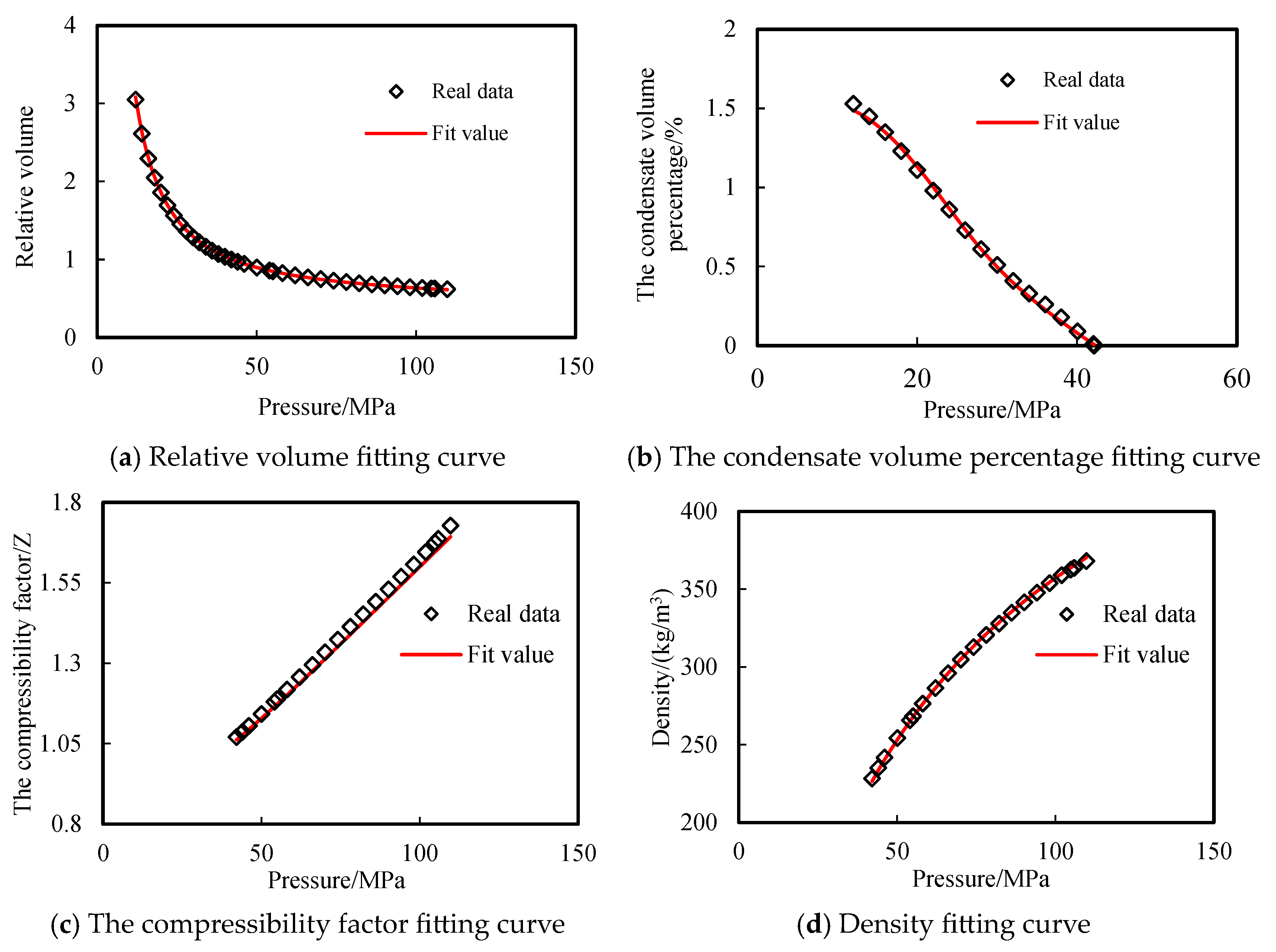
Figure 3 shows the relative volume (which is the ratio of the sample volume at each pressure to that at the dew-point pressure), the condensate volume percentage, and compressibility factor. It was found that over the expansion with decreasing pressure at the reservoir initial temperature, the relative volume changed from 0.6202 to 3.0492, the condensate volume percentage changed from 0 to 1.53%, and the compressibility factor varied from 1.7276 to 1.0704. With the decrease in pressure, the relative volume increased monotonically and the compressibility factor decreased monotonically. The condensate volume percentage rose rapidly below the dew-point pressure with the decrease in pressure. While with the increase in temperature, the condensate volume percentage declined due to evaporation, and the dew-point pressure dropped as well.
c.
Constant volume depletion
Table 3 shows the measured fluid composition, compressibility factor, recovery factor, and the amount of retrograde condensate over the pressure depletion process. As the pressure dropped from 42.11 MPa to 6 MPa, the content of C1–C5 increased slightly, the content of C1 rose from the initial 88.38% to the final 89.06%, and the content of C11+ decreased from 0.58% to 0.28%. It clearly shows that the fluid tended to be lighter and lighter during constant volume depletion. Figure 4 shows that when the pressure dropped below the dew-point pressure, p = 42.11 MPa, which is marked as * in Table 3, the amount of retrograde condensate increased. When the pressure dropped to p = 12 MPa, the content of the retrograde condensate reached the peak at 0.95%. A further decrease in pressure made the retrograde condensate smaller and smaller, which was caused by the evaporation of condensate under high temperature.

3. EOS Tuning

3.1. Phase Behavior Modeling

The experimental data were used to tune a Peng-Robinson EOS in a fluid property characterization tool, Winprop (CMG ltd., Canada). The tuning was regarded as satisfactory as the error between the theoretical value and the experimental data was below 20%. Figure 5 and Figure 6 show the respective errors for CCE and CVD experiments. Figure 7 shows all the differences between experimental data and the corresponding theoretical prediction. All of the errors in the data (137) were smaller than 16%, among which 129 data were below 5% and those with larger errors (>10%) took place in the tuning of the compressibility factor. This was caused by the small experimental data itself.
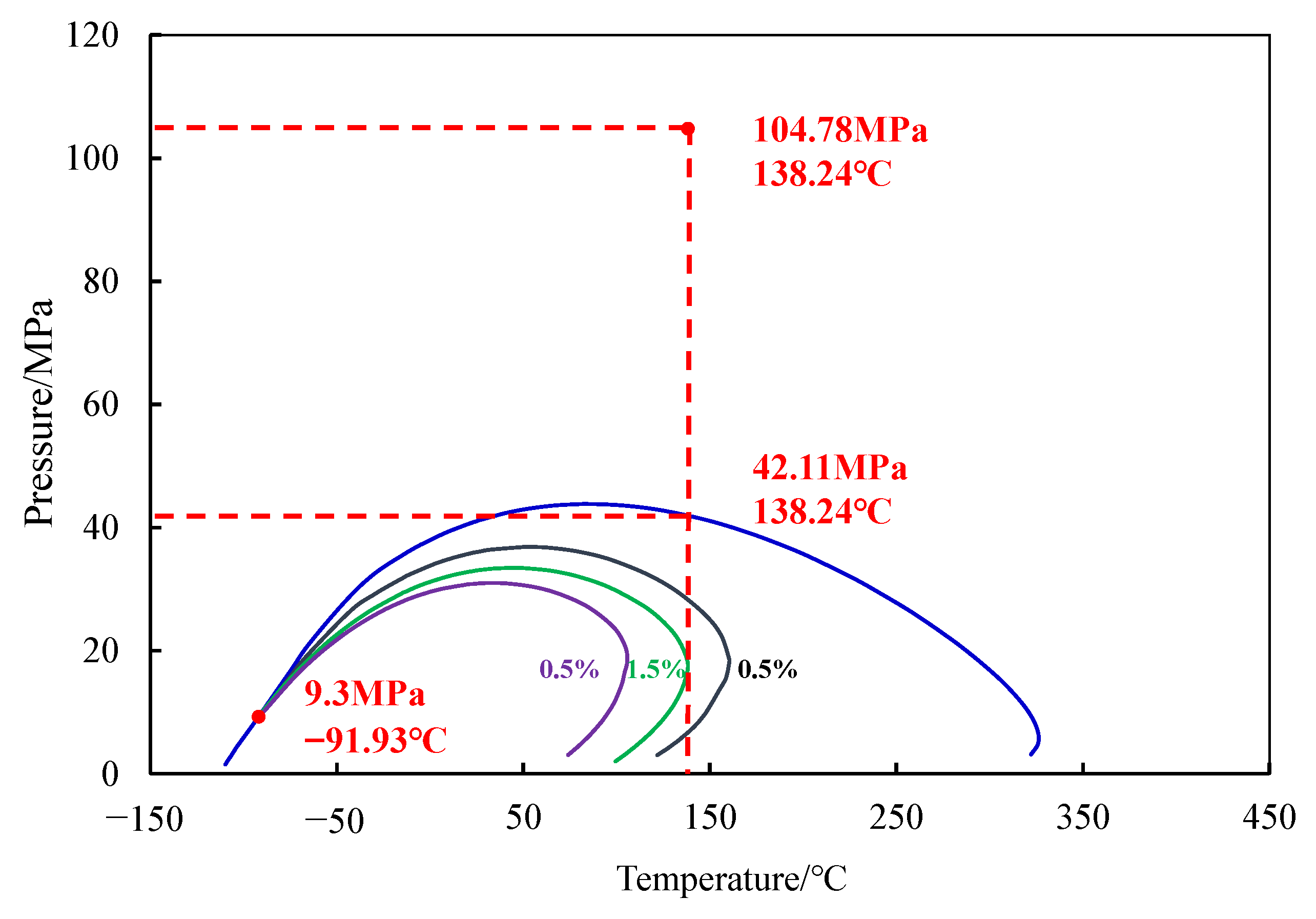
Figure 8 shows the phase diagram of the condensate, which indicated the target reservoir was a typical undersaturated condensate gas reservoir whose initial pressure was much higher than the dew-point pressure. The CVD data show that the maximum amount of retrograde condensate was 0.95%, implying the retrograde condensation would not be problematic. However, if the flowing bottom-hole pressure (BHP) and reservoir pressure drop below 42.11 MPa, there would be serious condensate banking near the wellbore.

3.2. Reservoir Modeling

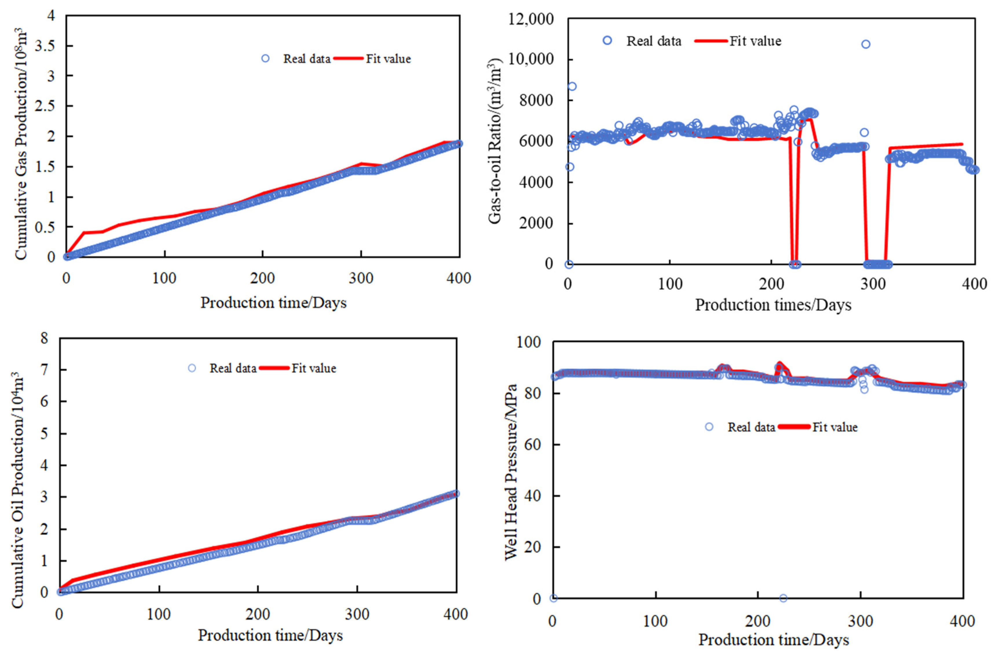
A dual-perm compositional reservoir model of the Bozi 3 Block was developed by using a commercial simulator GEM (CMG ltd., Canada) (Figure 9). Table 4 shows the basic physical properties and operation conditions regarding the numerical model. With the model, history match was first conducted for the BZ3 well production data, as shown in Figure 10. Then, the gas injection process was optimized via sensitivity analysis.

4. Injection Gas Selection

In order to eliminate the influence of heterogeneity in actual geological models, a conceptual model was established to select the rational injection gas type with the maximum condensate oil recovery. The reservoir was discretized in space as 118 × 59 × 5 (total grids = 34,810), with each grid having a dimension of 30 m × 30 m × 23 m. The other basic physical properties and operation conditions regarding the conceptual model were the same as the Bozi 3 reservoir model, as shown in Table 4. Two wells were set to simulate the retrograde condensation during the pressure decline process.
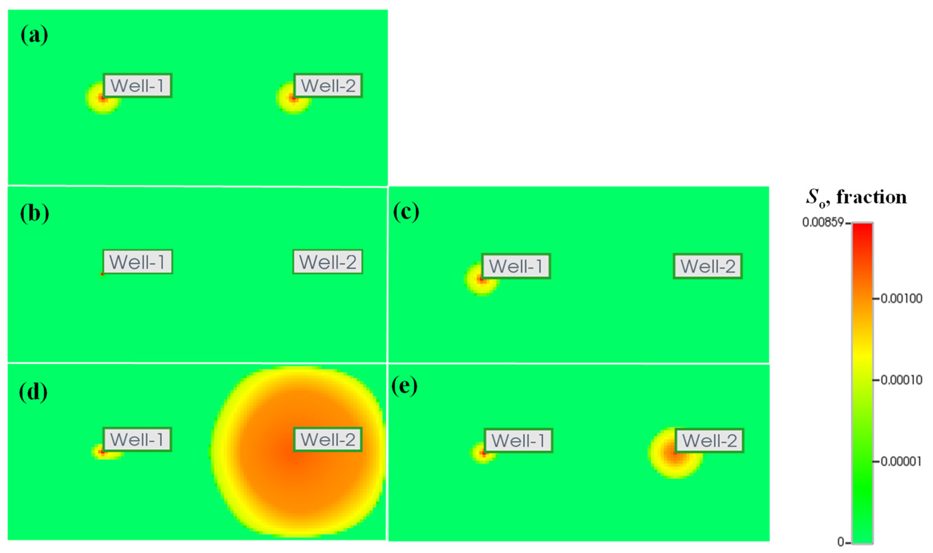
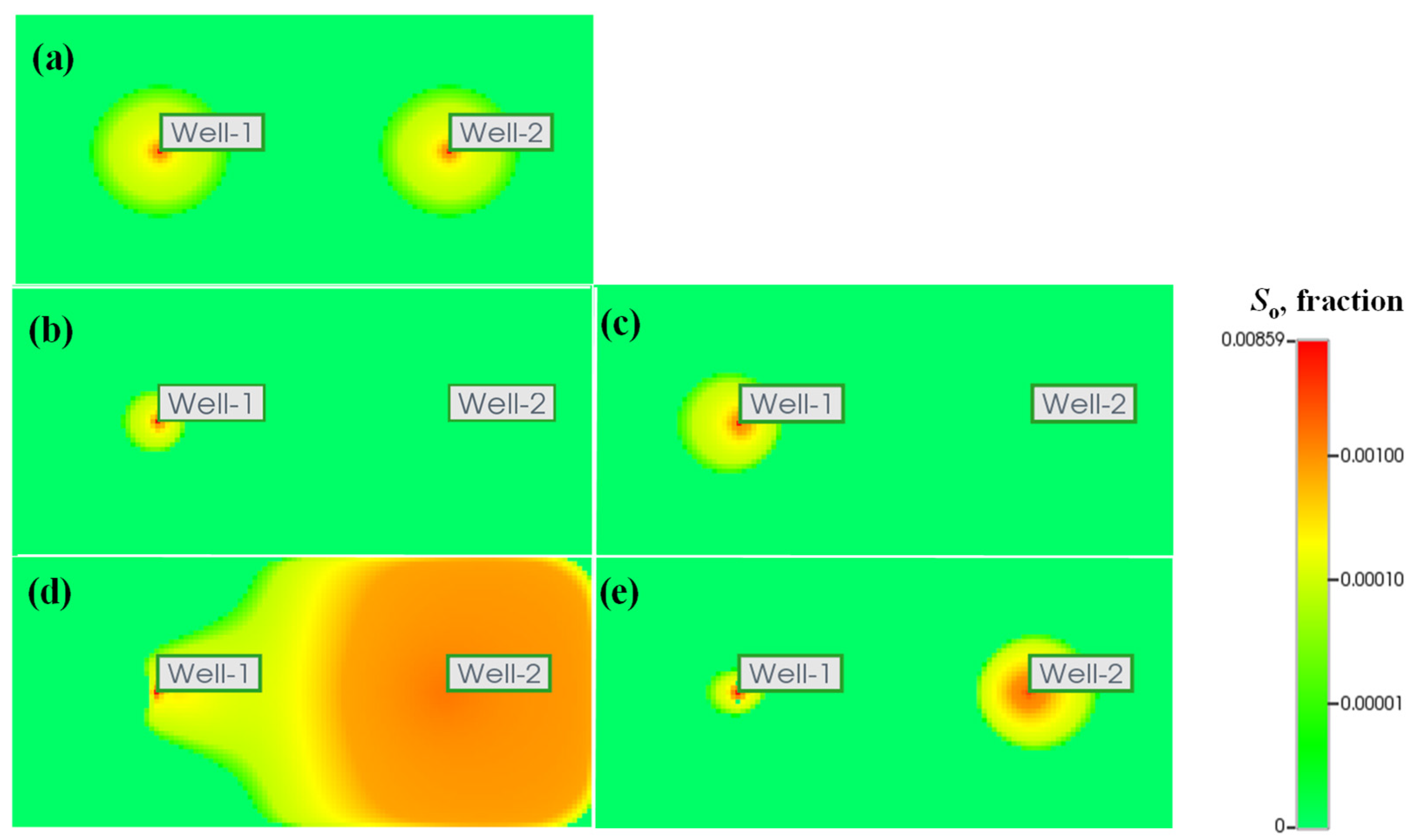
According to its production history of Bozi 3 Block, the retrograde condensation took place after 2600 days of production at a constant rate of q = 50 × 104 m3/d. Afterwards, methane, recycled dry gas (90.3% of C1 and 9.7% of C2+, CO2 and N2), nitrogen, and carbon dioxide were injected respectively into Well 2 at an injection rate of 50 × 104 m3/d for 1000 days, following a pressure depletion at the same rate of 50 × 104 m3/d. Figure 11, Figure 12, Figure 13, Figure 14 and Figure 15 compare their retrograde condensate saturations. It was found that: (1) the recovery mechanisms of methane and recycled gas were similar, maintaining the formation pressure and reducing the condensate oil saturation, which effectively alleviated the condensate blocking around the injection well. There was nearly no retrograde condensate between wells during gas injection. (2) Injecting nitrogen aggravated the retrograde condensation, because nitrogen increased the dew-point pressure and caused retrograde condensation to occur earlier. (3) Carbon dioxide injection created an extraction zone near the borehole, which inhibited retrograde condensation between wells. Overall, methane was identified as the optimal injection gas.

5. Sensitivity Analysis

5.1. Gas Injection Timing

Bozi 3 Block is a long and narrow anticline trap with a large east/west length and a small south/north width. The high point has an elevation of −3800 m, a burial depth of −5827 m, and a structural amplitude of 900 m. The east/west length is about 22.7 km and the south/north width 3 km, with a long axis/short axis ratio of about 7.6:1 and a coverage area of 55.42 km2.
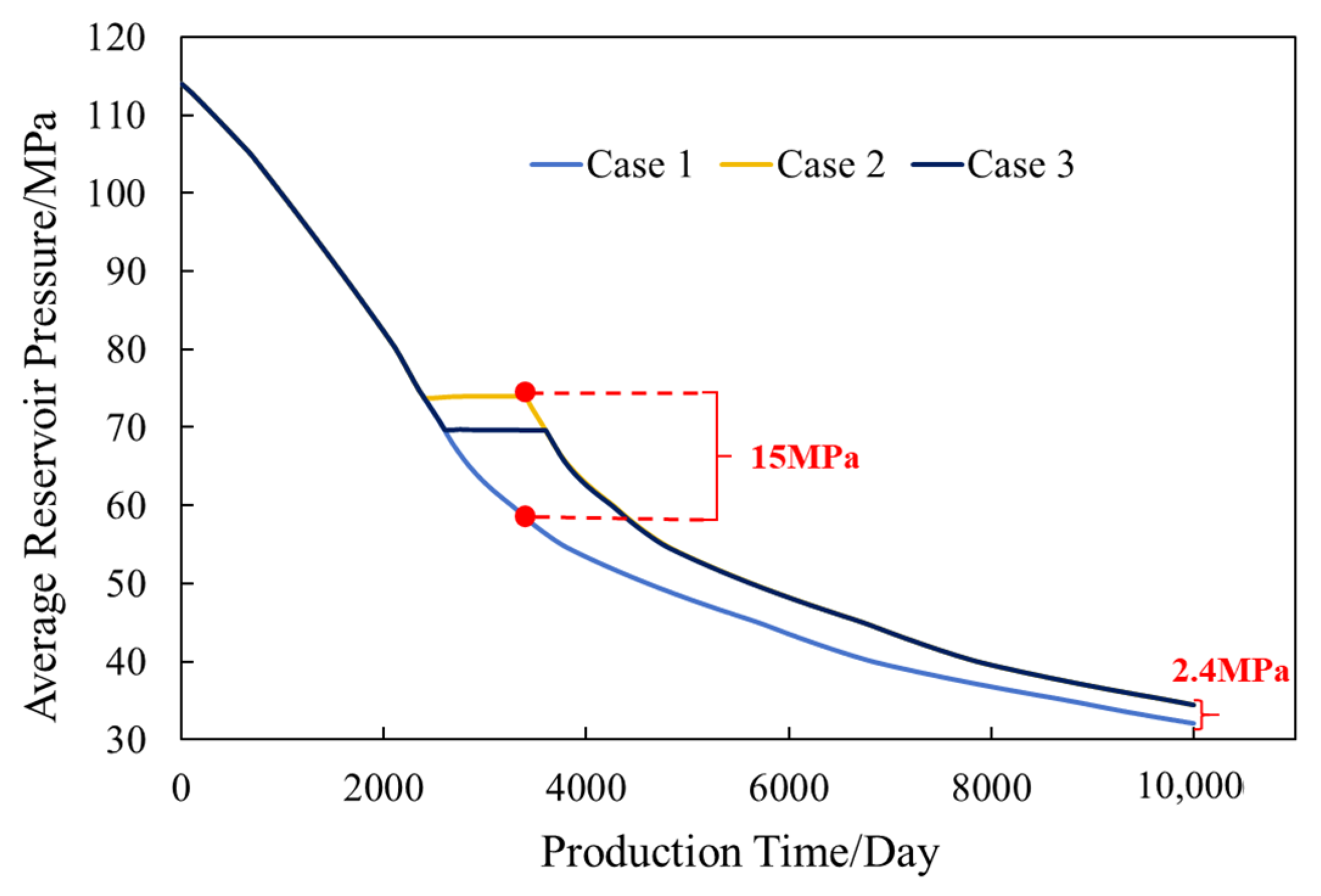
After 2400 days of depletion production, the Bozi 3 reservoir pressure dropped to the dew-point pressure and the pre-set production rate (q = 50 × 104 m3/d) did not stay stable at t = 2600th day. To determine the optimal timing for gas injection, three cases were run and compared. Case 1: depletion production for 10,000 days (base case); Case 2: injection of gas for 1000 days at t = 2400th day when BHP declined below dew-point pressure; and Case 3: injection of gas for 1000 days at t = 2600th day when the production rate started to drop. Table 5 shows the respective oil production of gas injection results.
It was found that Case 3 better improved the condensate oil recovery, which was 2.07% higher than that of Case 1. In addition, the average reservoir pressure increased by 2.4 MPa to 15 MPa after 1000 days of gas injection (Figure 16). When the BHP dropped below the dew-point pressure, a small amount of the condensate was separated near the borehole, as reflected by the CVD test data. Injecting methane at this moment (Case 2) raised the reservoir pressure, yet its oil production was not higher than that of Case 3.

5.2. Gas Injection Volume

To analyze the effects of gas injection volume in Bozi 3 Block, two more cases were run. Case 4: methane was injected for 2000 days when the reservoir pressure dropped to the dew-point pressure (at t = 2400th day); Case 5: methane was injected for 2000 days when the pre-set production rate became unstable (at t = 2600th day). Table 6 shows the respective oil production of gas injection results. With all the cases (Cases 1–5) compared, it was found that Case 3 had a higher oil production improvement, whereas the condensate oil production decreased by 1.15% and 0.58% in Case 4 and Case 5, respectively. The average reservoir pressure increased by 4.7 MPa–23 MPa (Figure 17). Moreover, it was clear that 2000 days of gas injection can over lift the reservoir pressure, resulting in a drop in condensate production. Therefore, the gas injection volume needed to be set in a reasonable range.

5.3. Injection and Extraction Position

There are six wells in the Bozi 3 Block, namely BZ3, BZ301, BZ3-1X, BZ3-2X, BZ3-3X, and BZ3-K2. The burial depth difference of the block is up to 40 m, and the perforations can be set at the upper or lower part of the reservoir. To optimize injection/production positions, three cases were analyzed. Case 6: injection at the upper part and production at the lower part (BZ3 well), Case 7: injection at the lower part and production at the upper part (BZ3-3X well), Case 8: simultaneous injection at both the upper and lower parts (BZ3 and BZ3-3X wells). Table 7 compares the corresponding simulation results. It was found that Case 8 had higher condensate oil production than the other two cases; its oil production was 8690.43 m3 more and recovery 2.75% higher than those of the base case. Case 8 reached a more effective production of condensate oil and obtained the largest recovery. Case 7 had better performance than Case 6 because the condensate oil was distributed more on the upper half of the reservoir.

6. Conclusions and Recommendation

(1)
Bozi 3 Block is a super deep condensate reservoir with a high temperature (138.24 °C) and high pressure (104.78 MPa). PVT experiments showed the composition of the fluid sample were: C1+N2: 89.16 mol.%, CO2+C2-C6: 9.04 mol.%, and C7+: 1.8 mol.%.
(2)
The phase diagram indicated that the critical temperature and pressure of the fluid were −91.93 °C and 9.30 MPa, respectively; the critical condensate temperature and pressure were 326.24 °C and 43.83 MPa, respectively.
(3)
Compositional reservoir simulation showed that the recovery mechanisms of methane and recycled gas injection were similar, maintaining the formation pressure and reducing the condensate oil saturation, which effectively mitigated the condensate blocking around the injection well. There was nearly no retrograde condensate between wells during gas injection. Injecting nitrogen aggravated the retrograde condensation. Carbon dioxide injection created an extraction zone near the borehole, which inhibited retrograde condensation between wells. Overall, methane was identified as the optimal injection gas.
(4)
Gas injection started when the production began to fall, achieving higher recovery than gas injection starting when the pressure fell below the dew-point pressure. When the production rate starts to fall, simultaneous injection of methane at both the upper and lower parts of the reservoir, at a rate of 50 × 104 m3/d for 1000 days, can effectively produce condensate oil over the entire block. This scheme achieved 8690.43 m3 more oil production and 2.75% higher recovery factor in comparison with depletion production.

Author Contributions

Conceptualization, J.S.; methodology, J.S.; software, H.D., X.J. and W.L.; validation, Y.T; formal analysis, B.Y.; investigation, Y.T.; resources, Y.Z.; data curation, G.F.; writing—original draft preparation, H.D.; writing—review and editing, X.J.; supervision, J.S.; project administration, Y.Z.; funding acquisition, Y.Z. All authors have read and agreed to the published version of the manuscript.

Funding

This study was supported by China National Petroleum Corporation’s Major Science and Technology Special Project “Research on Supporting Technologies for Efficient Development of Complex Reservoirs in Bozi-Dabei Region with Trillion Cubic Meters of Gas and Field Application” (No. TXN011020120001).

Data Availability Statement

Data are contained within the article.

Conflicts of Interest

Author Yongling Zhang and Yangang Tang were employed by the Tarim Oilfield Company. Author Haoxiang Dai and Bo Yang were employed by the China United Coalbed Methane Co. Author Wenbin Li was employed by the Research Institute of Oil Exploration and Development. The remaining authors declare that the research was conducted in the absence of any commercial or financial relationships that could be construed as a potential conflict of interest.

References

  1. Kamari, E.; Shadizadeh, S.R. An experimental phase diagram of a gas condensate reservoir. Pet. Sci. Technol. 2012, 30, 2114–2121. [Google Scholar] [CrossRef]
  2. Shi, J.; Huang, L.; Li, X.; Sepehrnoori, K. Production forecasting of gas condensate well considering fluid phase behavior in the reservoir and wellbore. J. Nat. Gas Sci. Eng. 2015, 24, 279–290. [Google Scholar] [CrossRef]
  3. Pan, Y.; Sun, L.; Luo, L.; Du, J.; Liu, J.; Tang, Y.; Shi, D. Experiment and analysis of oil/gas/water multi-phase behavior of condensate gas reservoir. J. Southwest Pet. Univ. (Sci. Technol. Ed.) 2006, 28, 48–51. [Google Scholar]
  4. Allahyari, M.; Aminshahidy, B.; Sanati, A.; Taghikhani, V. Analysis of near well-bore behavior of gas condensate reservoir in production stage. Pet. Sci. Technol. 2012, 30, 2594–2603. [Google Scholar] [CrossRef]
  5. Li, S.; Pan, Y.; Sun, L. A new idea on enhancing the recovery rate of condensate gas reservoirs. Nat. Gas Ind. 2008, 28, 1–5. [Google Scholar]
  6. Li, S.; Sun, L.; Du, J.; Tang, Y.; Zhou, S.; Guo, P.; Li, J. Difficulties and measures for development of low permeability tight gas reservoirs and condensate gas reservoirs. Xinjiang Pet. Geol. 2004, 25, 225–230. [Google Scholar]
  7. Li, M. Study on Condensate Saturation in Porous Media During Depletion and Gas Injection. Master’s thesis, Southwest Petroleum University, Chengdu, China, 2006. [Google Scholar]
  8. Zhu, H.; Shen, Y.; Fan, C.; Hu, J.; Yu, J. Gas injection to enhance oil recovery in condensate gas reservoirs. Inn. Mong. Petrochem. Ind. 2013, 18, 137–139. [Google Scholar]
  9. Wu, Y.; Yao, K.; Liu, Y.; Li, X.; Wu, M.; Cheng, R.; Wang, B. Experimental study on enhanced condensate recovery by gas injection in Yaha condensate gas reservoir. Geofluids 2021, 1, 7698970. [Google Scholar] [CrossRef]
  10. Jiang, T.; Sun, L.; Xie, W.; Xiao, X.; Wang, Y.; Xia, J. Three-element development mechanism of cyclic gas injection in condensate gas reservoirs and a new technique of enhancing condensate oil recovery. Acta Pet. Sin. 2021, 42, 137–139. [Google Scholar]
  11. Shi, J.; Li, X.; Zhou, J.; Li, Q.; Wu, K. How to evaluate and predict the deliverability change of gas condensate wells. Pet. Sci. Technol. 2014, 32, 442–449. [Google Scholar] [CrossRef]
  12. Chen, L.; Luo, J.; Rao, H.; Feng, X.; Kang, A.; Le, X. Gas injection EOR at mid-late development stage in condensate gas reservoirs. Xinjiang Pet. Geol. 2019, 40, 98–102. [Google Scholar]
  13. Li, S.; Guo, P.; Du, J.; Wang, Y. New way to improve gas well production and condensate gas field′ s recovery factor. J. Southwest Pet. Univ. (Sci. Technol. Ed.) 2007, 29, 1–6. [Google Scholar]
  14. Feng, Q.; Deng, B.; Yang, Y. Evaluations and removing methods of the retrograde condensate damage for the gas condensate reservoirs in the tight sandstone. Pet. Geol. Oilfield Dev. Daqing 2020, 39, 139–146. [Google Scholar]
  15. Li, G.; Guo, X.; Zi, Q.; Wu, S. Effect analysis of cyclic gas injection in fractured condensate gas reservoir. J. Southwest Pet. Univ. (Sci. Technol. Ed.) 2003, 25, 44–46. [Google Scholar]
  16. Zhu, W.; Zhang, F.; Tang, M.; Wang, H. Methods of cyclic gas injection to retard gas channeling in the Yaha condensate gas field. Nat. Gas Ind. 2008, 28, 76–77. [Google Scholar]
  17. Wan, T.; Sheng, J. Evaluation of the EOR potential in hydraulically fractured shale oil reservoirs by cyclic gas injection. Pet. Sci. Technol. 2015, 33, 812–818. [Google Scholar] [CrossRef]
  18. Jiao, Y.; Xie, W.; Di, B.; Liang, T.; Liu, L. Gas condensate phase behavior in process of cyclic gas injection. Xinjiang Pet. Geol. 2012, 33, 704–707. [Google Scholar]
  19. Kang, H.; Zhang, J.; Fan, X.; Huang, Z. Cyclic injection to enhance hydraulic fracturing efficiency: Insights from laboratory experiments. Geofluids 2020, 2020, 8844293. [Google Scholar] [CrossRef]
  20. Li, J.; Li, X.; Zhou, Y.; Kang, X.; Tong, M. New method of cyclic gas injection for condensate reservoirs. Nat. Gas Ind. 2004, 24, 76–79. [Google Scholar]
  21. Poordad, S.; Forutan, M.K. A review of the potential for CO2 sequestration and enhanced gas recovery in an Iranian gas condensate reservoir from a fluid properties point of view. Pet. Sci. Technol. 2013, 31, 2157–2165. [Google Scholar] [CrossRef]
  22. Fath, A.H.; Dashtaki, N.B. Evaluation of effective parameters on CO2 injection process in a gas condensate reservoir: A case study. Energy Sources Part A Recovery Util. Environ. Eff. 2016, 38, 3680–3686. [Google Scholar]
  23. Meng, X.; Meng, Z.; Ma, J.; Wang, T. Performance evaluation of CO2 huff-n-puff gas injection in shale gas condensate reservoirs. Energies 2018, 12, 42. [Google Scholar] [CrossRef]
  24. Wu, Z.; Sun, Z.; Shu, K.; Jiang, S.; Gou, Q.; Chen, Z. Mechanism of shale oil displacement by CO2 in nanopores: A molecular dynamics simulation study. Adv. Geo-Energy Res. 2024, 11, 141–151. [Google Scholar] [CrossRef]
  25. Wan, T.; Mu, Z. The use of numerical simulation to investigate the enhanced Eagle Ford shale gas condensate well recovery using cyclic CO2 injection method with nano-pore effect. Fuel 2018, 233, 123–132. [Google Scholar] [CrossRef]
  26. Narinesingh, J.; Alexander, D. CO2 enhanced gas recovery and geologic sequestration in condensate reservoir: A simulation study of the effects of injection pressure on condensate recovery from reservoir and CO2 storage efficiency. Energy Procedia 2014, 63, 3107–3115. [Google Scholar] [CrossRef]
  27. Nasriani, H.R.; Borazjani, A.A.; Sinaei, M.; Hashemi, A. The effect of gas injection on the enhancement of condensate recovery in gas condensate reservoirs: A comparison between a synthetic model and PVT cell results. Pet. Sci. Technol. 2014, 32, 593–601. [Google Scholar] [CrossRef]
  28. Barrufet, M.A.; Bacquet, A.; Falcone, G. Analysis of the storage capacity for CO2 sequestration of a depleted gas condensate reservoir and a saline aquifer. J. Can. Pet. Technol. 2010, 49, 23–31. [Google Scholar] [CrossRef]
  29. Song, Y.; Song, Z.; Chen, Z.; Zhang, L.; Zhang, Y.; Feng, D.; Wu, Z.; Wu, J. Fluid phase behavior in multi-scale shale reservoirs with nano-confinement effect. Energy 2024, 289, 130027. [Google Scholar] [CrossRef]
  30. Zhang, A.; Fan, Z.; Zhao, L. An investigation on phase behaviors and displacement mechanisms of gas injection in gas condensate reservoir. Fuel 2020, 268, 117–373. [Google Scholar] [CrossRef]
  31. Gu, Q.; Tang, Z.; Xian, B.; Huang, B.; Wang, Y.; Zhang, D. Application of gas-drive characteristic curve in condensate gas reservoir by methane injection development process. Xinjiang Pet. Geol. 2014, 35, 724–727. [Google Scholar]
  32. Bonyadi, M.; Esmaeilzadeh, F.; Mowla, D. Methane flooding in lean gas condensate reservoir. Energy Sources Part A Recovery Util. Environ. Eff. 2015, 37, 2240–2246. [Google Scholar] [CrossRef]
  33. Masoumi, S.; Helalizadeh, A.; Bahrami, M. The performance of various injecting gases into fractured retrograde gas reservoirs for revaporization of liquid drop–out. Pet. Sci. Technol. 2011, 29, 2536–2544. [Google Scholar] [CrossRef]
  34. Ghiri, M.N.; Nasrian, H.R.; Sinaei, M.; Najibi, S.H.; Nasrian, E.; Parchami, H. Gas injection for enhancement of condensate recovery in a gas condensate reservoir. Energy Sources Part A Recovery Util. Environ. Eff. 2015, 37, 799–806. [Google Scholar] [CrossRef]
  35. Syzdykov, M. Evaluating Gas Injection Performance in Very Low Permeability, Thick Carbonate Gas–Condensate Reservoirs to Improve Ultimate Liquid Yield. Master’s Thesis, Colorado School of Mines, Golden, CO, USA, 2014. [Google Scholar]
  36. Sadooni, M.; Zonnouri, A. The effect of nitrogen injection on production improvement in an Iranian rich gas condensate reservoir. Pet. Sci. Technol. 2015, 33, 422–429. [Google Scholar] [CrossRef]
  37. Davarpanah, A.; Mazarei, M.; Mirshekari, B. A simulation study to enhance the gas production rate by nitrogen replacement in the underground gas storage performance. Energy Rep. 2019, 5, 431–435. [Google Scholar] [CrossRef]
  38. Du, J.; Xiao, C.; Wang, Z. Laboratory study on the evaluation and removal of retrograde condensate damage in the Baka Gas Reservoir, Tuha Basin. Nat. Gas Ind. 2015, 35, 52–56. [Google Scholar]
  39. Pang, Z.; Liu, H.; Zhu, L. A laboratory study of enhancing heavy oil recovery with steam flooding by adding nitrogen foams. J. Pet. Sci. Eng. 2015, 128, 184–193. [Google Scholar] [CrossRef]
  40. Eid, M.E.G. Simulation Study to Determine the Feasibility of Injecting Hydrogen Sulfide, Carbon Dioxide and Nitrogen Gas Injection to Improve Gas and Oil Recovery Oil–Rim Reservoir. Master’s Thesis, The Petroleum Institute (United Arab Emirates), Abu Dhabi, United Arab Emirates, 2012. [Google Scholar]
  41. Zheng, X.; Shi, J.; Cao, G.; Yang, N.; Cui, M.; Jia, D.; Liu, H. Progress and prospects of oil and gas production engineering technology in China. Pet. Explor. Dev. 2022, 49, 644–659. [Google Scholar] [CrossRef]
  42. Mou, W.; Che, C.; Wang, X.; Deng, X.; Chen, S.; Cui, T.; Zong, W. Numerical simulation of exploration methods for Kekeya condensate oil–gas reservoir. Xinjiang Pet. Geol. 2007, 28, 94–96. [Google Scholar]
  43. GB/T 26981-2020; Analysis Method for Reservoir Fluid Physical Properties. National Standardization Administration of China: Beijing, China, 2020.
Figure 1. Technology roadmap.
Energies 17 05367 g001
Figure 2. Triangular phase diagram of sample composition.
Energies 17 05367 g002
Figure 3. Plot of CCE experimental results.
Energies 17 05367 g003
Figure 4. The content of retrograde condensate.
Energies 17 05367 g004
Figure 5. CCE fitting results.
Energies 17 05367 g005
Figure 6. CVD fitting results.
Energies 17 05367 g006
Figure 7. The differences between experimental data and the corresponding theoretical prediction.
Energies 17 05367 g007
Figure 8. The P-T phase diagram.
Energies 17 05367 g008
Figure 9. Model diagram of Bozi 3.
Energies 17 05367 g009
Figure 10. Production dynamic history fitting.
Energies 17 05367 g010
Figure 11. Retrograde condensate saturations for 3000 days. (a) 3000 day’s depletion; (b) 2600 day’s depletion+400 days’ CH4 injection; (c) 2600 day’s depletion+400 days’ recycle gas injection; (d) 2600 day’s depletion+400 days’ N2 injection; (e) 2600 day’s depletion+400 days’ CO2 injection.
Energies 17 05367 g011
Figure 12. Retrograde condensate saturations for 3100 days. (a) 3100 day’s depletion; (b) 2600 day’s depletion+500 days’ CH4 injection; (c) 2600 day’s depletion+500 days’ recycle gas injection; (d) 2600 day’s depletion+500 days’ N2 injection; (e) 2600 day’s depletion+500 days’ CO2 injection.
Energies 17 05367 g012
Figure 13. Retrograde condensate saturations for 3200 days. (a) 3200 day’s depletion; (b) 2600 day’s depletion+600 days’ CH4 injection; (c) 2600 day’s depletion+600 days’ recycle gas injection; (d) 2600 day’s depletion+600 days’ N2 injection; (e) 2600 day’s depletion+600 days’ CO2 injection.
Energies 17 05367 g013
Figure 14. Retrograde condensate saturations for 3500 days. (a) 3500 day’s depletion; (b) 2600 day’s depletion+900 days’ CH4 injection; (c) 2600 day’s depletion+900 days’ recycle gas injection; (d) 2600 day’s depletion+900 days’ N2 injection; (e) 2600 day’s depletion+900 days’ CO2 injection.
Energies 17 05367 g014
Figure 15. Retrograde condensate saturations for 4550 days. (a) 4550 day’s depletion; (b) 2600 day’s depletion+1000 days’ CH4 injection+ 950 day’s depletion; (c) 2600 day’s depletion+1000 days’ recycle gas injection+ 950 day’s depletion; (d) 2600 day’s depletion+1000 days’ N2 injection+ 950 day’s depletion; (e) 2600 day’s depletion+1000 days’ CO2 injection+ 950 day’s depletion.
Energies 17 05367 g015
Figure 16. Variation in the average pressure of the reservoir.
Energies 17 05367 g016
Figure 17. Variation in the average pressure of the reservoir.
Energies 17 05367 g017
Table 1. Fluid sampling check.
Sampling Depth/mVial Volume/mLSampler NumberingTemperature/20 °CSample Type
External Pressure/MPaTurn on the Pressure/MPa
7200700818,7969681.9Condensate
Table 2. Composition of the Bozi 3 reservoir fluid sample.
ComponentFlash OilFlashWell Flow
% (Molar Score)% (Molar Score)% (Molar Score)g/m3
H2S0.000.000.00
N20.000.800.78
CO20.000.380.38
C10.0090.1688.38
C20.006.996.8585.62
C30.000.810.7914.48
iC40.340.310.317.49
nC40.720.320.337.97
iC51.220.130.164.80
nC51.290.090.113.30
C65.430.000.113.84
C716.510.000.3313.17
C823.380.000.4620.46
C912.450.000.2512.57
C108.960.000.1810.03
C11+29.710.000.5849.91
total100.00100.00100.00233.64
C11+Relative molecular weight203.5
C11+Relative density0.8279
Table 3. Test data of constant volume depletion (138.24 °C).
Pressure, MPa42.11 *36.0030.0024.0018.0012.006.00
The compressibility factor Z1.07041.00660.95660.91190.89660.90300.9435
Two-phase compressibility factor1.07040.92950.90600.87470.85720.85140.8583
Cumulative percentage of extraction 10.7621.2434.8949.5066.4683.33
Viscosity/mPa·s0.02780.02540.02310.02080.01880.01710.0158
Composition/mol %
N2Nitrogen0.780.860.750.710.720.740.73
CO2Carbon dioxide0.380.360.380.390.380.380.39
C1Methane88.3888.6788.8388.7989.0389.2089.06
C2Ethane6.856.626.886.996.886.877.00
C3Propane0.790.820.820.840.830.820.85
iC4Isobutane0.310.330.330.350.340.330.35
nC4n-butane0.330.340.360.380.380.360.38
iC5Isopentane0.160.200.180.200.190.180.19
nC5n-pentane0.110.150.130.140.140.130.14
C6Hexane0.110.090.080.070.060.060.05
C7Heptane0.330.280.230.210.190.170.16
C8Octane0.460.400.330.290.260.240.22
C9Nonane0.250.210.170.160.140.130.12
C10Decane0.180.150.130.110.100.090.08
C11+Undecane or more0.580.520.400.370.360.300.28
Total100.00100.00100.00100.00100.00100.00100.00
C11+ molecular weight203.5199.7195.9192.2188.4184.6184.9
C11+ relative density0.82790.82410.82030.81660.81280.80900.8098
* means the dew point pressure.
Table 4. Basic parameters of the model.
ParameterValuesUnitSource
Reservoir pressure104.78MPaGeological data
Reservoir temperature138.24°CPVT data
Matrix permeability0.024mDGeological data + historical fitting adjustment
Matrix porosity6%Geological data + historical fitting adjustment
Water saturation36%Geological data
Net gross ratio0.32/Geological data + historical fitting adjustment
Crack permeability10mDGeological data + historical fitting adjustment
Crack porosity0.1%Geological data + historical fitting adjustment
Crack density5strip/mGeological data + historical fitting adjustment
Table 5. Sensitivity analysis for injection timing.
OptionCase 1Case 2Case 3
Development ApproachDepletion developmentInject at the
Dew-point pressure
Inject when
production is reduced
Timing of injection/Day/24002600
Injection duration/Days/10001000
Final oil production/m3571,901573,871574,755
Oil production before injection/m3/403,089434,261
Increase oil production/m3/19702854
Proportion of condensate production increase/1.17%2.07%
Cumulative gas production/m33.56 × 1094.03 × 1094.03 × 109
Injection volume/m3/5.00 × 1085.00 × 108
Gas boost/m3/4.63 × 1084.65 × 108
Total loss of gas volume/m3/3.67 × 1073.54 × 107
Table 6. Sensitivity analysis for injection volume.
OptionCase 1Case 4Case 5
Development approachDepletion developmentInject at the
Dew-point pressure
Inject when
production is reduced
Timing of injection/Days/24002600
Injection duration/Days/20002000
Final oil production/m3571,901569,967.25571,098
Oil production before injection/m3/403,089434,261
Increase oil production/m3/−1933.98−802.281
Proportion of condensate production increase/−1.15%−0.58%
Cumulative gas production/m33.56 × 1093.48 × 1093.48 × 109
Injection volume/m3/1.00 × 1091.00 × 109
Gas boost/m3/9.17 × 1089.17 × 108
Total loss of gas volume/m3/8.29 × 1078.28 × 107
Table 7. Sensitivity analysis for injection and production positions.
OptionInjection MethodGas Injection ConceptIncrease Oil ProductionPercentage of Increase in Production
Case 6BZ3 inject (K1bs)Injection at the upper part and production at the lower part6193.911.96%
Case 7BZ3-3X inject (K1bx)Injection at the lower part and production at the upper part6731.132.13%
Case 8BZ3 and BZ3-3X injectSimultaneous injection at both the upper and lower parts8690.432.75%
Case 1No Injection (Depletion development)///
Disclaimer/Publisher’s Note: The statements, opinions and data contained in all publications are solely those of the individual author(s) and contributor(s) and not of MDPI and/or the editor(s). MDPI and/or the editor(s) disclaim responsibility for any injury to people or property resulting from any ideas, methods, instructions or products referred to in the content.