Article

Low-Frequency Electrical Heating for In Situ Conversion of Shale Oil: Modeling Thermal Dynamics and Decomposition

by
Zhaobin Zhang
1,2,3,*,
Zhuoran Xie
1,2,3,
Maryelin Josefina Briceño Montilla
1,2,3,
Shouding Li
1,2,3 and
Xiao Li
1,2,3
1
Key Laboratory of Shale Gas and Geoengineering, Institute of Geology and Geophysics, Chinese Academy of Sciences, Beijing 100029, China
2
Institute of Earth Sciences, Chinese Academy of Sciences, Beijing 100049, China
3
College of Earth and Planetary Sciences, University of Chinese Academy of Sciences, Beijing 100049, China
*
Author to whom correspondence should be addressed.
Energies 2024, 17(21), 5401; https://doi.org/10.3390/en17215401
Submission received: 15 September 2024 / Revised: 18 October 2024 / Accepted: 26 October 2024 / Published: 30 October 2024

Abstract

:
In situ conversion presents a viable strategy for exploiting low to moderate maturity shale oil. Traditional methods, however, require dense well patterns and substantial energy, which are major hurdles. This study introduces a novel approach employing low-frequency electrical heating via production wells to enhance heat transfer without necessitating additional heating wells. Utilizing a self-developed simulator, we developed a numerical model to evaluate the efficacy of this method in augmenting reservoir temperature and facilitating substance decomposition. Findings indicate that low-frequency electrical heating significantly elevates reservoir temperatures, accelerates hydrocarbon cracking, and boosts fluid production. A sensitivity analysis on various heating strategies and reservoir characteristics showed that elevated heating power can further pyrolyze the heavy oil in the product to light oil, while higher porosity formations favor increased oil and gas output. The study also explores the effect of thermal conductivity on heating efficiency, suggesting that while better conductivity improves heat distribution, it may increase the proportion of heavy oils in the output. Overall, this investigation offers a theoretical foundation for refining in situ conversion technologies in shale oil extraction, enhancing both energy efficiency and production quality.

1. Introduction

Continental shale oil with low thermal maturity constitutes a substantial supply of hydrocarbons for the sustainable advancement of China’s oil sector [1]. These resources exhibit reduced thermal maturity of organic content, increased fluid viscosity, diminished mobility, and greater residual amounts of shale oil [2]. Consequently, the in situ heating process has arisen as a viable method for resource extraction [3]. However, the exploration of shale oil encounters many challenges, including complex geological conditions, high development costs, limited progress in key technologies, and the fact that studies are still in the preliminary phases, with no commercial implementation yet [4].
In situ heating methods for shale oil reservoirs involve injecting heat directly into the rock formation to speed up the natural process of turning kerogen into hydrocarbons. Recently, several in situ heating technologies have emerged to develop this type of reservoir [5]. For instance, the in situ conversion process (ICP) has been one of the first methods carried out by Shell in the Green River Formation [6]. The method has achieved promising results and has served as a base for multiple studies that involve numerical analysis, optimization research, and experimental studies [7,8,9,10]. On the other hand, some have proposed steam injection as a potential technology [11], given its success in heavy oil reservoirs [12]. Experiments indicate that the steam injection can achieve oil recovery rates between 60% and 95% and increase the petrophysical properties of the reservoirs [13,14]. Researchers have also explored the injection of other fluids, such as air and nitrogen. Air injection triggers an exothermic reaction that is beneficial for generating heat in situ [15,16,17,18]. Furthermore, studies have demonstrated that nitrogen and air injection can improve energy efficiency [19]. Although these technologies show potential results, the energy consumption for the development generates a certain resistance to the application [20]. Some authors suggest introducing the possibility of utilizing shale oil reservoirs for energy storage, leveraging high power fluctuations from solar and wind sources for in situ conversion [21]. However, it is necessary to test more heat source alternatives that can help optimize the development of these types of formations.
Electromagnetic fields, such as microwave heating, for heat reservoirs have been widely used in heavy oil reservoirs [22]. In electromagnetic techniques, the energy is converted into heat in situ using a system of electrodes, creating an electromagnetic field [23]. The Radio Frequency technology of Raydeon presents a patent technology that combines radio frequency heating (microwave heating) for shale oil reservoirs [24]. In this case, microwave heating refers to the use of electromagnetic waves with wavelength (1 mm–1 m) and frequency (300 MHz–300 GHz) [25]. However, the high energy consumption represents a bottleneck problem leading to a high cost in addition to other logistical problems [24].
Low-frequency heating for electrical heating is introduced as an additional technology applied for the production of bitumen from the Alberta oil sands [26]. This is a method of generating heat by applying low-frequency electromagnetic fields, typically in the range of 30 kHz to 300 MHz. McGee and Vermeulen [27] present the Electro-Thermal Dynamic Stripping Process, a patented commercial electro-thermal method that involves low-frequency heating. In this process, low-frequency current travels through ionic conduction in the water-saturated interconnected pore spaces, transferring heat to the formation through conduction [23]. Consequently, low-frequency (LF) electric heating demonstrates efficacy in delivering heat to bitumen sandstones, thereby diminishing oil viscosity and enhancing mobility [28]. Low-frequency electric heating, combined with depressurization, has also been shown to significantly enhance gas recovery from Class 1 hydrate deposits [29]. Recent advancements have shown great promise for enhancing gas production from methane hydrate deposits [30].
These results show that low-frequency electrical heating is an effective way to get the maximum energy out of complex reservoirs. They also show that electromagnetic heating has the potential to increase thermal energy, which can help with hydrocarbon extraction. Because low-frequency electrical heating is efficient in other reservoir types, its application to shale oil has the potential to improve energy transfer and recovery rates. Oil shale fields, like those in Colorado, have applied electromagnetic spectrum technologies with promising results in synthetic fuel production [31]. Despite this success, there is a notable absence of recent field applications or modeling studies specifically investigating low-frequency heating in shale oil reservoirs. Therefore, in this research, we perform a numerical analysis to evaluate the feasibility and effectiveness of low-frequency energy heating for shale oil recovery, with the aim of addressing this gap and exploring its potential benefits in shale oil production.
The low-frequency electric heating model in reservoirs involves a dynamic process where heat, mass, and electromagnetic fields are strongly coupled [28]. Using a self-developed simulator (accessible at IGG-Hydrate: https://gitee.com/geomech/hydrate, accessed on 25 October 2024), we account for the complex heterogeneity of continental shale oil formations and incorporate a kinetic model to better represent the thermal and chemical processes involved. The configuration of the model includes a single well that functions both as a heating and production well during different phases of the process, which helps reduce operational costs. The proposed method follows a treatment timeline of five years, with two years dedicated to injection, one year for pressure stabilization, and two years for production. This approach presents a comprehensive analysis of the direction of heat flow that opposes the direction of fluid flow, which complicates uniform heat distribution within the reservoir. This misalignment is a documented limitation [32], as it reduces the efficiency of heat transfer into the formation. Addressing these challenges is critical to optimizing the heating process, improving energy efficiency, and ultimately enhancing oil recovery from shale formation.

2. Model Construction

2.1. Numerical Methods

This study employs a self-development simulator that has been implemented in several research projects [21,33,34,35]. This multiphase and multicomponent thermo-flow–chemical coupling simulator is capable of replicating the complex process in the in situ conversion of oil shale. The pyrolysis of shale oil involves multiphase and multicomponent flow, thermal transport, and chemical reactions. Therefore, we incorporate the following assumptions to simplify the model calculations:
  • In this model, the phases are defined as follows: the aqueous phase consists mostly of liquid water; the gas phase includes both steam and CH4; and the solid phase is composed of kerogen and coke. Moreover, liquid hydrocarbons—heavy oil and light oil—are modeled as distinct fluids due to the pronounced variations in their viscosities and densities, which necessitate their separate treatment.
  • To simplify the pyrolysis of shale oil and to compute the thermophysical and transport properties, this model proposes that heavy oil, light oil, and natural gas consist solely of C22H46, C11H24, and CH4, respectively.
  • The flow of each fluid phase obeys Darcy’s law.
The numerical simulator used in this simulation accounts for the fluid phase flow, heat transfer, and phase change. The governing equations, representing mass and energy balance, are expressed in the integral form as follows in Table 1. The simulation incorporates phase transitions, including water evaporation and condensation, as well as kerogen pyrolysis and heavy oil cracking according to [10,36]:
K e r o g e n 0.6   C 22 H 46 + 0.1   C 11 H 24 + 0.1   C H 4 + 0.1   H 2 O + 0.1   C o k e
C 22 H 46 0.5   C 11 H 24 + 0.2   C H 4 + 0.3   C o k e
The pyrolysis of kerogen and heavy oil cracking is governed by the reservoir temperature. Two essential parameters for these reactions are the critical reaction temperatures—565 K for kerogen and 603 K for heavy oil—and the activation energies, which are 161.6 kJ/mol and 206.0 kJ/mol, respectively [37].
Table 1. Main equations used in this study.
DescriptionEquation
Darcy’s law (flow velocity of fluids) v α = k k r , α μ α p α + ρ α g
The mass conservation equation ϕ ρ α s α t = div ρ α v α
The modified version of Stone’s relative permeability method [38] k r , α = s α s i r , α 1 s i r , α n α
Heat transfer (heat convection and conduction) q h e a t = λ T + α ρ α c α v α T
Heat transfer (heat convection and conduction) div q h e a t = ϕ α ρ α c α s α + ρ s c s T t

2.2. Verifications

Since the model incorporates the chemical decomposition process and heavy oil cracking, the validation of this process is necessary. The experiment conducted by Pei et al. [39] is used to evaluate the kinetic model. The experiment consists in the decomposition of heavy oil at temperatures exceeding 623.15 K, exhibiting a reaction rate constant of 1.21 × 10 6   s 1 . The experimental apparatus is applied in heavy oil with a density of 1007 kg/m3, a viscosity of 191.6 Pa·s, and a mass of 0.02 kg at initial temperature and pressure parameters of 599.15 K and 3.2 MPa. The pyrolysis products in the numerical model were expressed as mass stoichiometric factors, yielding 0.5608 light oil, 0.1721 gas, and 0.2671 coke. In addition, the models have been validated through multiple approaches, including laboratory studies, classical models, and field studies [21,33,34,35]. The chemical simulation results closely matched the actual data, confirming its precision in simulating the in situ conversion process (Figure 1).

2.3. Model Settings

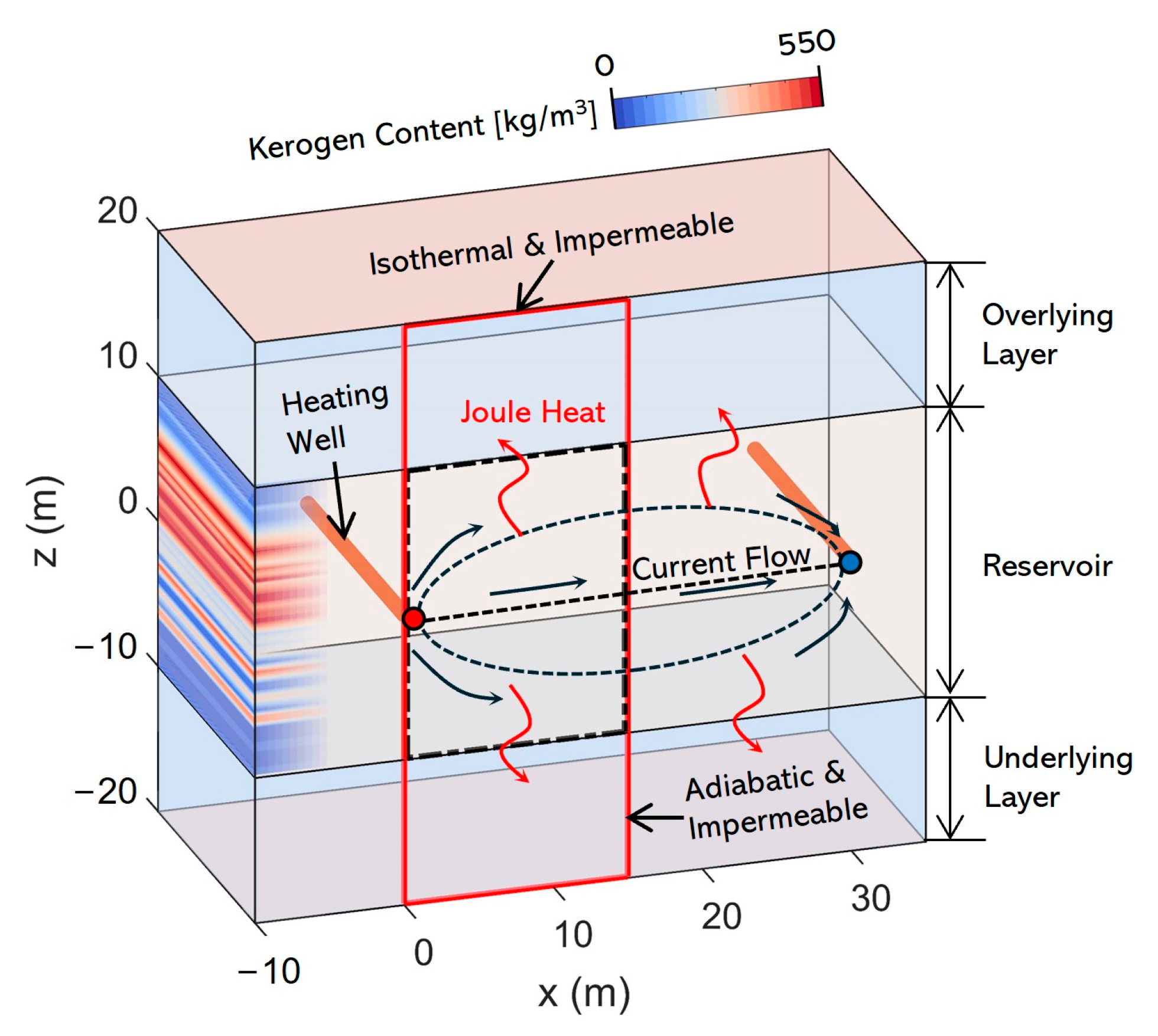
We established a geological model based on the aforementioned simulator to simulate the in situ conversion process of shale oil. It is assumed that the shale oil reservoir consists of a 10 m thick overlying layer, a 20 m thick shale oil layer, and a 10 m thick underlying layer (Figure 2). The reservoir is set as homogeneous and anisotropic, with the horizontal permeability set to 10 mD and the vertical permeability set to 2 mD. This setup is based on a comprehensive consideration of the shale matrix and fracture development within the reservoir. The saturation distribution of the various components in the shale oil reservoir is according to [40]. Given that oil and gas are produced through a single-well huff-and-puff process, we assumed a large-scale horizontal well network periodically arranged along the x-axis. The distance between the two adjacent wells is 30 m, and both are located along the horizontal symmetry axis of the shale oil reservoir. By applying voltage to the two adjacent wells, an electric current is generated within the reservoir to achieve heating. Considering the symmetry and periodicity of the above structure, we conducted actual calculations for a region 15 m in length and 40 m in height, with the horizontal well located at the far left of this area. The boundaries of the computational domain are impermeable and isothermal at the top and bottom, and impermeable and adiabatic at the sides.
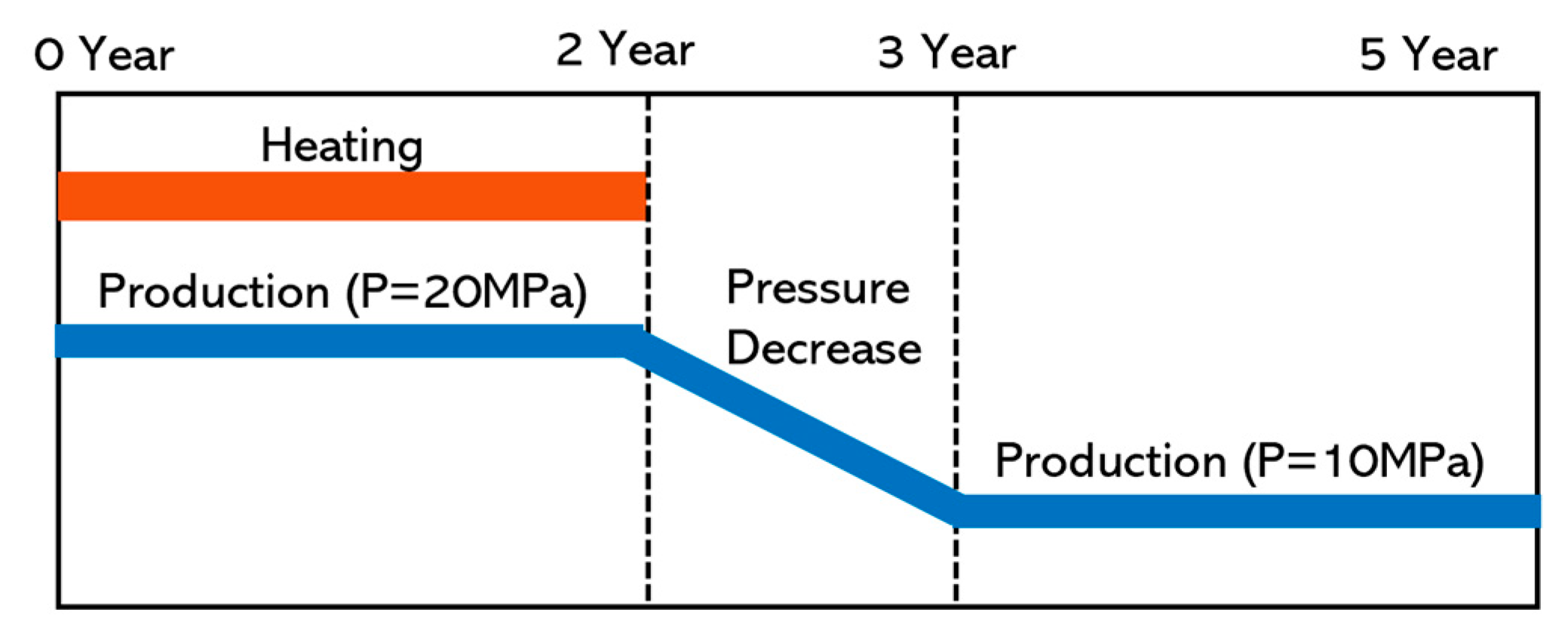
We simulated the in situ shale oil conversion process for a total duration of 5 years (Figure 3), divided into three stages. In the first two years, the reservoir was simultaneously heated and produced through the horizontal well, with a production pressure of 20 MPa. In the subsequent stage, heating was stopped, but production from the shale oil reservoir continued through the horizontal well. Unlike the first two years, the third year involved a pressure-reduction stage, where the production pressure was gradually reduced from 20 MPa to 10 MPa to enhance production. The final two years continued production at a pressure of 10 MPa. More specific parameters involved in this process are detailed in Table 2.

3. Results

3.1. Evolution of Temperature

After heating begins, heat is generated at a location slightly distant from the horizontal well and spreads outward from the well through heat conduction. The rate of heat transfer depends on the thermal conductivity of the reservoir medium. As the reservoir is homogeneous and anisotropic, the thermal conductivity in the horizontal direction is greater than in the vertical direction, resulting in the formation of an elliptical high-temperature zone centered around the horizontal well (Figure 4a–c). As heating continues, the high-temperature zone within the reservoir gradually expands outward. The center of the high-temperature zone exhibits the highest temperature, which is also the location of the maximum temperature in the entire reservoir. During the heating stage, the maximum temperature in the reservoir continues to rise, though the rate of increase slows in the later stage. This may be because the heating power remains constant, but in the later stage of heating, a larger area of the reservoir needs to be heated simultaneously, and the pyrolysis of organic matter within the reservoir also consumes part of the energy. After heating ends, the maximum temperature in the reservoir immediately begins to decrease, but the overall average temperature of the reservoir does not decline due to the cessation of heating and the energy consumption from the pyrolysis of organic matter. Instead, it remains at a relatively stable level. This is because, although the reservoir no longer receives external heat, the ultra-high temperature zone formed near the horizontal well during the heating stage continues to heat the reservoir. During the subsequent production phase, the temperature distribution within the reservoir gradually becomes more uniform.
The heating ratio refers to the proportion of the reservoir that reaches the kerogen pyrolysis temperature during the heating process (Figure 4d). Around 0.5 years into heating, some areas of the reservoir begin to reach this threshold. After heating ends, this proportion rapidly decreases but does not fall to zero until approximately 4.5 years later. It is necessary to note that this does not mean kerogen pyrolysis continued until this point, as most of the kerogen within the high-temperature zones had already undergone complete pyrolysis. However, it is evident that the residual heat in the reservoir after heating can still support the continued pyrolysis of kerogen.

3.2. Pyrolysis Characteristics

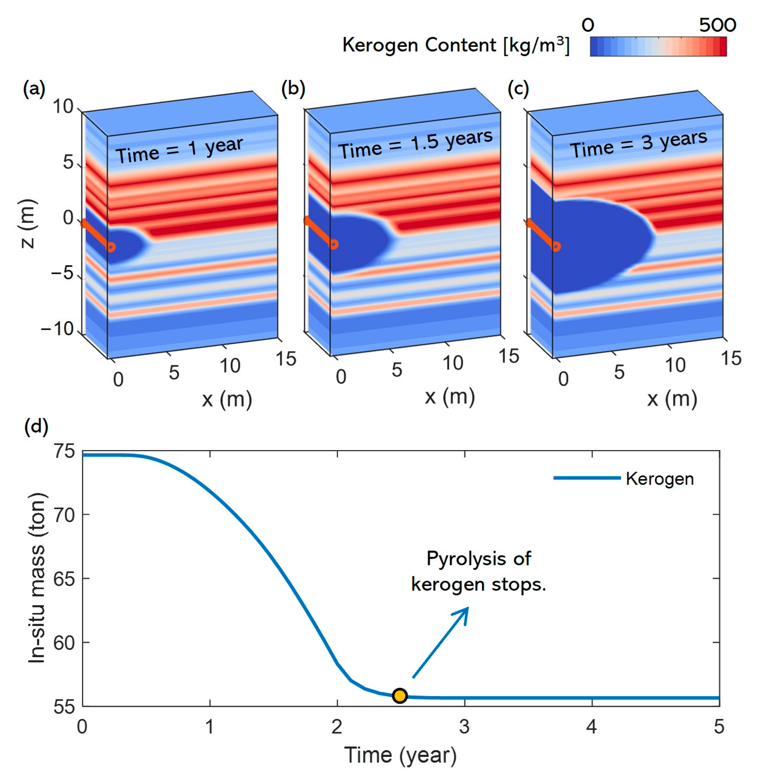
The evolution process of various reservoir components is influenced by multiple factors, including reservoir temperature, fluid properties, and pressure gradients. In the early stages of heating, the most important phenomena in the reservoir are the pyrolysis of kerogen and the pyrolysis of heavy oil. Due to the difference in pyrolysis temperatures between kerogen and heavy oil (with the critical pyrolysis temperatures being 565 K and 603 K, respectively), the timing of the onset of pyrolysis for the two substances also differs. The pyrolysis of kerogen begins first, as pyrolysis occurrence depends entirely on whether the reservoir has reached the critical temperature. Therefore, the area where kerogen pyrolysis occurs resembles the shape of the high-temperature zone in the reservoir (Figure 5a–c). However, since the temperature within the high-temperature zone decreases gradually from the center of the horizontal well outwards, the temperature on the outer edges of this zone may not reach the critical value. As a result, while the pyrolysis area is similar to the high-temperature zone, it is relatively smaller. Figure 5d shows the variation in the total kerogen content within the reservoir. As heating continues, the rate of decline in kerogen content accelerates. This is due to the continuous expansion of the high-temperature zone during the heating phase, causing more kerogen to undergo pyrolysis over a larger area of the reservoir. It is also noteworthy that the pyrolysis of kerogen did not stop immediately after the two-year heating stage ended, but continued for approximately 2.5 years before ceasing completely.
Among the various components involved in the in situ shale oil conversion process, the evolution of heavy oil is relatively complex. It acts both as a reactant undergoing pyrolysis under high temperatures and as a product during the pyrolysis of kerogen. Additionally, unlike kerogen, heavy oil is flowable and can be produced through horizontal well. Consequently, the trend in the total content of heavy oil in the reservoir is not stable, exhibiting significant fluctuations, especially during the heating stage. However, overall, the evolution of heavy oil can be divided into three stages (Figure 6):
(a)
In the early stage of heating, the maximum temperature in the reservoir reaches the pyrolysis temperature of kerogen but not that of heavy oil. During this stage, heavy oil primarily receives input from the pyrolysis of kerogen and does not undergo pyrolysis itself. However, heating and production occur simultaneously, and some heavy oil may be extracted through the horizontal well during this phase. Due to the high viscosity of heavy oil and its relatively low concentration near the well, the production rate is low. As a result of these combined factors, the total content of heavy oil in the reservoir remains relatively stable during this stage.
(b)
Since the difference in pyrolysis temperatures between heavy oil and kerogen is not significant, the first stage is relatively short (about 0.7 years). During the subsequent heating process, the temperature near the wellbore reaches the level required for heavy oil pyrolysis. At this point, heavy oil and kerogen undergo pyrolysis simultaneously. The heavy oil near the wellbore is almost completely pyrolyzed, and the remaining heavy oil is displaced to the outer areas of the wellbore by the light oil and other substances produced. Near the wellbore, there is almost no heavy oil during this stage, and the heavy oil in the reservoir no longer decreases due to production but is primarily consumed through pyrolysis. However, since the continuous heating causes more kerogen to undergo pyrolysis, the supply of heavy oil still exceeds the amount consumed by pyrolysis. As a result, the total content of heavy oil in the reservoir continues to increase, forming a high-saturation heavy oil layer outside the horizontal well. This stage persists until the end of the heating process.
(c)
After heating ends and the light oil and other substances within the heavy oil layer have been extracted through the horizontal well, heavy oil moves toward the wellbore due to pressure differences and concentration gradients, subsequently occupying the pores near the production well and being produced. At this stage, both the pyrolysis of heavy oil and kerogen in the reservoir cease, making the production of heavy oil the only factor leading to the decline in its content within the reservoir.
Light oil, as a common product of kerogen and heavy oil pyrolysis, is also one of the key products obtained through the horizontal well during in situ shale oil conversion. During the heating stage, as kerogen and heavy oil continue to undergo pyrolysis, the total amount of light oil in the reservoir steadily increases. Since the light oil layer is generated from the pyrolysis of heavy oil and kerogen within the high-temperature zone near the horizontal well, the light oil layer becomes enclosed by the surrounding layers of heavy oil and kerogen (Figure 7). Additionally, the distribution of light oil within the reservoir is influenced by the timing of the onset of pyrolysis of kerogen and heavy oil. The light oil layer near the wellbore is divided into two zones, with the internal light oil having a higher saturation than the external. The outermost light oil is a product of the pyrolysis of kerogen alone, whereas the light oil layer closer to the horizontal well results from the combined pyrolysis of both heavy oil and kerogen, and thus has a higher saturation.
Methane, as another common product of the pyrolysis of heavy oil and kerogen, exists in the reservoir in gaseous form, with both its viscosity and density being lower than those of other liquid and solid components in the reservoir (Figure 8). Consequently, the evolution of methane in the reservoir is influenced by gravity. During the heating stage, methane is divided into three parts after its formation: some of the methane, after its formation, immediately moves upwards under the influence of gravity and pressure differences, eventually forming a high-saturation methane gas layer above the reservoir. Another portion of methane becomes trapped within the heavy oil layer, while some escapes from the reservoir through the horizontal well during its formation. The total methane content in the reservoir is mainly influenced by two factors: the supply from the pyrolysis of organic matter and the decrease in methane content due to extraction by the horizontal well. In the early stage of heating, the supply exceeds the production, leading to a gradual increase in methane content within the reservoir. However, as heating continues, the organic matter in the reservoir undergoes complete pyrolysis. Additionally, due to the pyrolysis of kerogen and other materials, the porosity and permeability of the reservoir improve, facilitating methane production. This results in a turning point at 2 years, where production surpasses the supply from pyrolysis. Finally, the methane in the upper part of the reservoir, furthest from the horizontal well, is also extracted due to the pressure differential, marking the end of methane production in the reservoir.
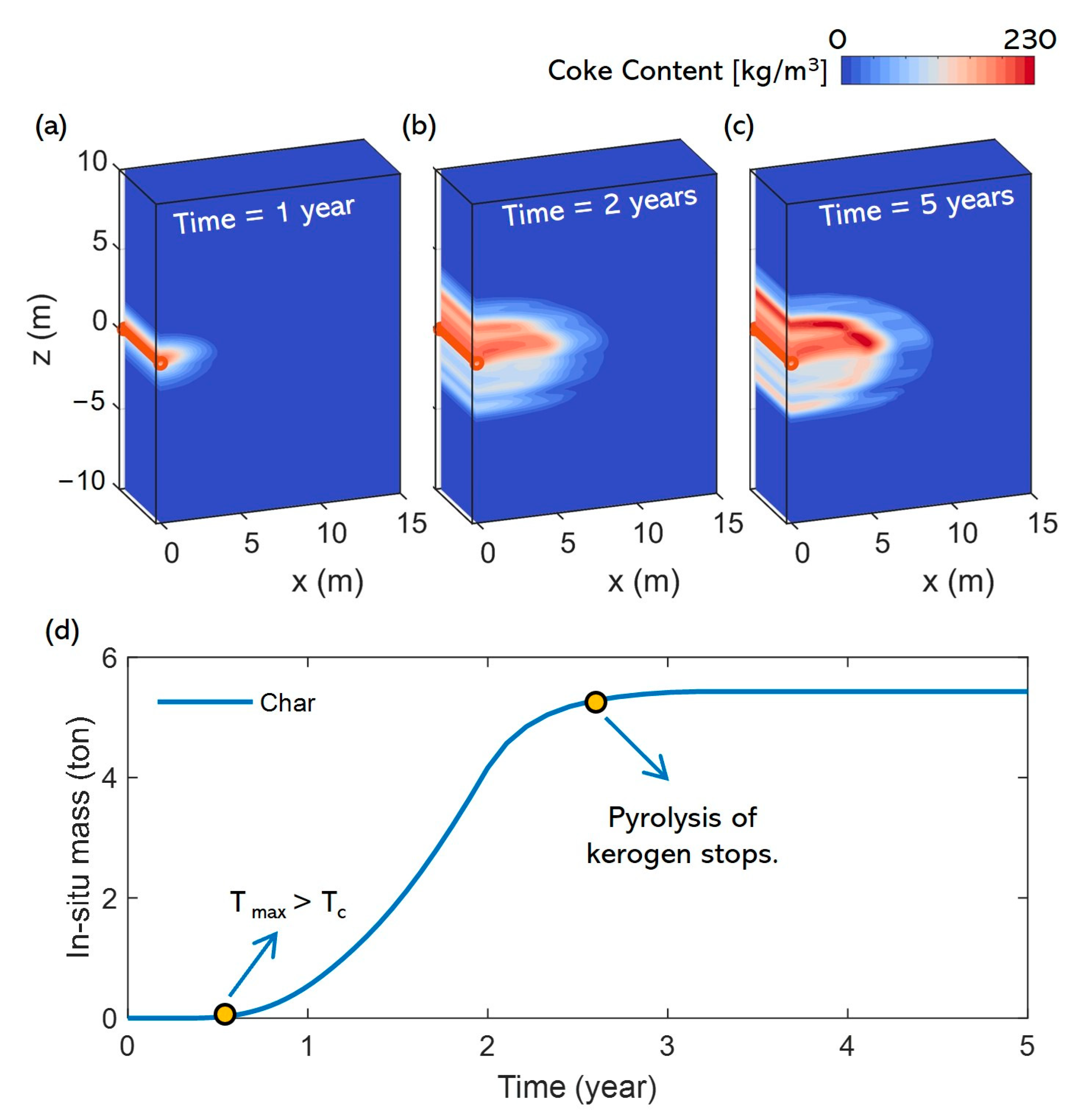
Coke is another product of organic matter pyrolysis, but unlike light oil and methane, it exists as a solid in the reservoir and lacks flowability, meaning it cannot be produced through the horizontal well (Figure 9). The amount of coke in the reservoir only increases with ongoing organic matter pyrolysis, making it a good indicator of whether the pyrolysis reaction is progressing. The amount of coke begins to increase at around 0.5 years, which is roughly the same time as the maximum temperature in the reservoir reaches the critical pyrolysis temperature for kerogen. The coke content continues to rise for approximately 2.5 years, aligning with the period during which kerogen continues to pyrolyze due to residual heat. Additionally, the distribution of coke in the reservoir exhibits characteristics similar to that of light oil: the higher saturation of coke near the horizontal well is the product of the combined pyrolysis of heavy oil and kerogen, while the lower saturation farther out is the product of kerogen pyrolysis alone.

3.3. Production Characteristics

In the previous sections, we analyzed the evolution of various components within the reservoir throughout the in situ conversion process. Since the goal of in situ shale oil conversion is to produce the oil and gas generated from pyrolysis, it is necessary to further conduct a quantitative analysis of the production of each component. Theoretically, all mobile phases in the reservoir (heavy oil, light oil, methane, and water) can be produced through pressure differentials and concentration gradient. However, due to differences in their viscosity and distribution within the reservoir, the production sequence and yields exhibit distinct characteristics. Since the single well in this study is responsible for both heating and production, the oil and gas generated from pyrolysis can be produced shortly after their formation. The first component to be produced is heavy oil. Shortly after the start of the in situ conversion process, heavy oil begins to leave the reservoir through the production well, even before the pyrolysis of kerogen starts (Figure 10a). This portion of heavy oil likely originates from the pre-existing reservoir, and its low content results in a slow production rate at the beginning. As the reservoir temperature reaches the kerogen pyrolysis threshold, the production rate of heavy oil rapidly increases. However, as the temperature continues to rise, reaching the pyrolysis temperature of heavy oil, nearly all of the heavy oil near the horizontal well is pyrolyzed, with the remaining portion displaced outward by light oil and other components, leading to the cessation of heavy oil production. Light oil and methane then become the primary products (Figure 10b,c). Due to the lower viscosity of methane, it flows more rapidly, resulting in a relatively fast production process, with most of the methane being produced within 1.5 years. On the other hand, light oil has a higher viscosity, which theoretically makes its production more challenging. However, since almost all the generated light oil is located near the horizontal well, it requires little migration and can be produced directly after formation. The production of light oil proceeds simultaneously with the heating process. At the end of heating, its production rate reaches its peak, which is also due to the fastest pyrolysis of heavy oil and kerogen in the reservoir, and a large amount of light oil is generated. The process of production is nearly complete within one year after the heating ends.
After the production of light oil and methane near the wellbore is completed, the heavy oil that was displaced to the outer region will migrate back into the pores near the wellbore under the influence of pressure difference and concentration gradient, allowing for secondary production (Figure 10a). The onset of this secondary production occurs almost simultaneously with the cessation of light oil and methane production and continues until the end of the in situ conversion process. In the later stages of the in situ conversion process, the production of substances other than heavy oil has almost ceased. This suggests that reducing the production pressure after heating ends to promote further production within the reservoir mainly affects heavy oil recovery. Additionally, it is important to note that water, which is also a significant byproduct of kerogen pyrolysis, will be produced through the horizontal well (Figure 10d). The cumulative production and production rate of water follow trends similar to those of light oil and methane, and production largely ceases after the heating process ends.
In this study, we applied low-frequency electric heating technology to the in situ conversion of shale oil reservoirs, enabling the simultaneous extraction of oil and gas through a single-well huff-and-puff process while heating the reservoir. Extraction efficiency is improved, allowing for the rapid production of heavy oil, light oil, and other substances shortly after heating begins. In existing in situ shale oil conversion technologies, a large-scale well network is typically required within the reservoir, with some wells designated as heating wells to inject heat into the reservoir, while the remaining wells serve as production wells to extract the oil and gas. In such extraction schemes, due to the distance between heating and production wells, the oil and gas generated near the heating wells must rely on their own mobility to migrate to the production wells under pressure differentials and concentration gradients. This places higher demands on the reservoir’s permeability. Therefore, before employing this method for shale oil extraction, hydraulic fracturing is often carried out to enhance permeability, or during production, fluids such as carbon dioxide are injected into the reservoir to displace the shale oil. In the shale oil extraction method used in this study, a single well performs both the heating and production functions, thereby eliminating the need for oil and gas to migrate from heating wells to production wells. Consequently, this mining method perhaps does not require high permeability of the reservoir. This will be further analyzed in the sensitivity analysis section. Additionally, since a single well performs multiple functions, the layout of the well network has been simplified, reducing the number of wells needed by at least half. This significantly lowers the cost of well network installation. However, it is undeniable that this method of extracting shale oil also presents some challenges. Firstly, it is crucial to plan the well spacing appropriately. This requires a clear understanding of the area around each well that can be effectively heated and produced to avoid under-exploitation due to sparse well placement, while also preventing increased costs due to overly dense well placement. Secondly, since heating and production occur simultaneously, this can result in heat leaving the reservoir without adequate transfer, potentially leading to energy waste. This requires further sensitivity analysis of more parameters involved in in situ transformation of shale oil.

3.4. Sensitivity Analysis

Analysis of the baseline model for in situ shale oil conversion revealed that, after extraction, unpyrolyzed organic matter remained in the reservoir, and some of the pyrolyzed oil and gas were not produced. Additionally, we found that the injected heat was not fully utilized for organic matter pyrolysis, as it primarily concentrated around the horizontal well, raising the temperature in this area to very a high level, while areas farther from the horizontal well were not adequately heated. The occurrence of the phenomenon may be related to the heating strategy and the properties of reservoir. Therefore, in this section, we selected several parameters that could potentially affect energy utilization efficiency and the flow of oil and gas (such as heating power, reservoir porosity, thermal conductivity, and permeability) for a sensitivity analysis. It is worth noting that during the sensitivity analysis of the target parameters, all other parameters remain consistent with the baseline model. Additionally, the target parameters are varied within a range of one-third to three times their corresponding values in the baseline model.
Since the heating duration is fixed, changing the heating power means altering the amount of heat injected into the reservoir. As observed in Figure 11a, the content of light oil, methane, and water in the final product increases with the rise in heating power. However, for heavy oil, a slight increase in production is observed initially with increased heating power, but further increases in heating power reduce the heavy oil content in the product. Clearly, injecting more heat into the reservoir allows more organic matter to undergo pyrolysis, resulting in the production of more light oil and other products. During the pyrolysis process, since the pyrolysis temperature of kerogen is relatively low, the heat injected into the reservoir will first act on the kerogen. Initially increasing the heat injection can promote the pyrolysis of more kerogen, leading to the production of more heavy oil. However, further increasing the heat injection will almost completely pyrolyze the kerogen in the reservoir, leaving the excess heat to act primarily on the heavy oil, pyrolyzing it into light oil and other products. This explains the reduction in heavy oil production. Moreover, analysis of the baseline model reveals that by the end of production, a significant amount of unextracted heavy oil remains in the reservoir. The remaining heat can further decompose this portion of heavy oil into more easily extractable oil and gas, which also increases the content of light oil and methane in the final product.
The porosity of the reservoir represents its capacity to store oil and gas resources per unit volume. Although the original organic content of the reservoir remains consistent during the sensitivity analysis of reservoir porosity, the overall volume of fluids within the pores increases after the pyrolysis of heavy oil and kerogen. In reservoirs with higher porosity, more generated oil and gas can be stored per unit volume, reducing the amount of oil and gas forced to migrate outward from the horizontal well. As a result, the pyrolyzed oil and gas are more concentrated around the production well, making extraction easier, thereby increasing the overall production (Figure 11b). Additionally, analysis of the evolution process of each component in the baseline model reveals that heavy oil requires the longest migration distance for production. Therefore, an increase in porosity has the most significant effect on promoting heavy oil production. Since the high-temperature zone is concentrated near the horizontal well, and heavy oil tends to be concentrated in this region in reservoirs with higher porosity, more thorough pyrolysis can be achieved. This is also one of the reasons why the production of light oil and other substances increases with porosity.
In this study, the in situ conversion of shale oil was conducted using low-frequency electric heating. Heat is transferred within the reservoir through heat conduction, making the rate of heat transfer primarily dependent on the reservoir’s thermal conductivity. In reservoirs with higher thermal conductivity, the injected heat can heat a larger portion of the reservoir within the same time frame. However, since the amount of injected heat is constant, an increase in thermal conductivity expands the heating range but fails to raise the temperature within that range to higher levels. In the actual simulation, increasing the reservoir’s thermal conductivity resulted in higher heavy oil production, while the content of light oil, methane, and other products decreased (Figure 11c). This indicates that a larger area of kerogen indeed underwent pyrolysis, yielding more heavy oil, but this also meant that the remaining heat in the reservoir was insufficient to further pyrolyze the heavy oil into light oil. Consequently, the composition of the final product displayed the trend.
The permeability of the reservoir affects fluid flow rates and the process of heat convection, thereby influencing shale oil extraction. However, as shown in Figure 11d, the cumulative production of various oil and gas substances in shale oil reservoirs with different permeabilities shows almost no variation. First, heat is mainly transferred through heat conduction within the reservoir, meaning changes in permeability have little effect on heat transfer. Second, in the in situ conversion process studied in this paper, both heating and production are conducted through the same well. The oil and gas products generated from organic matter pyrolysis are located near the production well and can be extracted with minimal migration. Therefore, the reservoir’s permeability does not play a significant role in controlling the oil and gas migration process. Additionally, analysis of the component evolution in the baseline model reveals that the only substance that migrates over longer distances within the reservoir is heavy oil. During the heating stage, heavy oil is displaced by light oil produced from further pyrolysis to areas outside the horizontal well, but in low-permeability reservoirs, the displacement distance is short, and the heavy oil can quickly migrate back near the well when production begins. Therefore, permeability also has a minimal impact on heavy oil production. In summary, the reservoir permeability has little effect on the shale oil in situ conversion and extraction method employed in this study.

4. Conclusions

This study utilized a novel thermo-flow–chemical coupled simulator to model the in situ conversion process of shale oil. In this process, low-frequency electric heating was employed to heat the reservoir, enabling heat injection and production of generated oil and gas through a single well. We conducted a detailed characterization of the evolution of various components within the reservoir and performed a sensitivity analysis on reservoir characteristics and heating strategy parameters that could potentially impact shale oil extraction. Based on the simulation results, the following conclusions can be drawn:
  • The use of low-frequency electric heating to heat the reservoir allows for the extraction of shale oil through a single well, thereby improving production efficiency. Additionally, this method does not require high reservoir permeability, making it suitable for tight shale oil reservoirs with low permeability.
  • In the process of in situ shale oil conversion, the production of heavy oil is divided into two stages because of pyrolysis and displacement by light oil and other substances, and this production will continue for an extended period.
  • The sensitivity analysis of heating strategies and reservoir properties revealed that higher heating power can reduce the proportion of heavy oil in the products, allowing further pyrolysis into light oil and other substances. Additionally, reservoirs with higher porosity are conducive to oil and gas production. Conducting in situ shale oil conversion in formations with better thermal conductivity may improve heating efficiency but also increase the proportion of heavy oil in the products.

Author Contributions

Conceptualization, Z.Z. and S.L.; methodology, Z.Z. and M.J.B.M.; software, Z.Z.; validation, Z.X., S.L. and X.L.; data curation, Z.X.; writing—original draft preparation, Z.X. and Z.Z; writing—review and editing, Z.X. and Z.Z.; visualization, Z.X.; supervision, X.L. All authors have read and agreed to the published version of the manuscript.

Funding

This research was funded by the National Natural Science Foundation of China (Grant No. 42090023), the Key Deployment Program of Chinese Academy of Sciences (Grant Nos: YJKYYQ20190043, ZDBS-LY-DQC003, KFZD-SW-422, ZDRW-ZS-2021-3-1), the Scientific Research and Technology Development Project of China National Petroleum Corporation (Grant No. 2022DJ5503) and CAS Key Technology Talent Program.

Data Availability Statement

The data presented in this study are available in the Section 3 in this article.

Conflicts of Interest

The authors declare no conflicts of interest.

References

  1. Hu, S.; Zhao, W.; Hou, L.; Yang, Z.; Zhu, R.; Wu, S.; Bai, B.; Jin, X. Development potential and technical strategy of continental shale oil in China. Shiyou Kantan Yu Kaifa/Pet. Explor. Dev. 2020, 47, 819–828. [Google Scholar] [CrossRef]
  2. Zhao, W.; Zhu, R.; Hu, S.; Hou, L.; Wu, S. Accumulation contribution differences between lacustrine organic-rich shales and mudstones and their significance in shale oil evaluation. Pet. Explor. Dev. 2020, 47, 1160–1171. [Google Scholar] [CrossRef]
  3. Crawford, P.M.; Biglarbigi, K.; Dammer, A.R.; Knaus, E. Advances in world oil shale production technologies. In Proceedings of the SPE Annual Technical Conference and Exhibition, Denver, CO, USA, 21–24 September 2008; pp. 4101–4111. [Google Scholar] [CrossRef]
  4. Wang, X.; Zhang, G.; Tang, W.; Wang, D.; Wang, K.; Liu, J.; Du, D. A review of commercial development of continental shale oil in China. Energy Geosci. 2022, 3, 282–289. [Google Scholar] [CrossRef]
  5. Crawford, P.M.; Killen, J.C. New challenges and directions in oil shale development technologies. In Oil Shale: A Solution to the Liquid Fuel Dilemma; Ogunsola, O.I., Hartstein, A.M., Ogunsola, O., Eds.; American Chemical Society: Washington, DC, USA, 2010; Chapter 2; Volume 1032, pp. 21–60. [Google Scholar] [CrossRef]
  6. Fowler, T.D.; Vinegar, H.J. Oil shale ICP—Colorado field pilots. In Proceedings of the SPE Western Regional Meeting 2009, San Jose, CA, USA, 24–26 March 2009; pp. 270–284. [Google Scholar] [CrossRef]
  7. Fan, Y.; Durlofsky, L.J.; Tchelepi, H.A. Numerical simulation of the in-situ upgrading of oil shale. SPE J. 2010, 15, 368–381. [Google Scholar] [CrossRef]
  8. Huang, H.; Yu, H.; Xu, W.; Lyu, C.; Micheal, M.; Xu, H.; Liu, H.; Wu, H. A coupled thermo-hydro-mechanical-chemical model for production performance of oil shale reservoirs during in-situ conversion process. Energy 2023, 268, 126700. [Google Scholar] [CrossRef]
  9. Ryan, R.C.; Fowler, T.D.; Beer, G.L.; Nair, V. Shell’s in situ conversion process-from laboratory to field pilots. ACS Symp. Ser. 2010, 1032, 161–183. [Google Scholar] [CrossRef]
  10. Lee, K.; Moridis, G.J.; Ehlig-Economides, C.A. A Comprehensive simulation model of kerogen pyrolysis for the in-situ upgrading of oil shales. SPE J. 2016, 21, 1612–1630. [Google Scholar] [CrossRef]
  11. Lee, K.; Moridis, G.; Ehlig-Economides, C. In situ upgrading of oil shale by Steamfrac in multistage transverse fractured horizontal well system. Energy Sources A Recovery Util. Environ. Eff. 2016, 38, 3034–3041. [Google Scholar] [CrossRef]
  12. Riveros, G.V.; Barrios, H. Steam injection experiences in heavy and extra-heavy oil fields, Venezuela. In Proceedings of the SPE International Heavy Oil Conference and Exhibition 2011, Kuwait City, Kuwait, 12–14 December 2011; pp. 265–279. [Google Scholar] [CrossRef]
  13. Yang, D.; Zhao, Y.; Kang, Z. Numerical simulation of in situ exploitation of oil shale by injecting high-temperature steam. Oil Shale 2019, 36, 483–500. [Google Scholar] [CrossRef]
  14. Wang, L.; Yang, D.; Zhao, J.; Zhao, Y.; Kang, Z. Changes in oil shale characteristics during simulated in-situ pyrolysis in superheated steam. Oil Shale 2018, 35, 230–241. [Google Scholar] [CrossRef]
  15. Ifticene, M.A.; Yuan, C.; Al-Muntaser, A.A.; Onishchenko, Y.V.; Emelianov, D.A.; Varfolomeev, M.A. Behavior and kinetics of the conversion/combustion of oil shale and its components under air condition. Fuel 2022, 324, 124597. [Google Scholar] [CrossRef]
  16. Khakimova, L.; Bondarenko, T.; Cheremisin, A.; Myasnikov, A.; Varfolomeev, M. High pressure air injection kinetic model for Bazhenov Shale Formation based on a set of oxidation studies. J. Pet. Sci. Eng. 2019, 172, 1120–1132. [Google Scholar] [CrossRef]
  17. Gao, Y.; Wan, T.; Dong, Y.; Li, Y. Numerical and experimental investigation of production performance of in-situ conversion of shale oil by air injection. Energy Rep. 2022, 8, 1099–1112. [Google Scholar] [CrossRef]
  18. Martins, M.F.; Salvador, S.; Thovert, J.F.; Debenest, G. Co-current combustion of oil shale—Part 1: Characterization of the solid and gaseous products. Fuel 2010, 89, 144–151. [Google Scholar] [CrossRef]
  19. Pei, S.; Wang, Y.; Zhang, L.; Huang, L.; Cui, G.; Zhang, P.; Ren, S. An innovative nitrogen injection assisted in-situ conversion process for oil shale recovery: Mechanism and reservoir simulation study. J. Pet. Sci. Eng. 2018, 171, 507–515. [Google Scholar] [CrossRef]
  20. Brandt, A.R.; Boak, J.; Burnham, A.K. Carbon dioxide emissions from oil shale derived liquid fuels. ACS Symp. Ser. 2010, 1032, 219–248. [Google Scholar] [CrossRef]
  21. Zhang, Z.B.; Montilla, M.J.B.; Li, S.D.; Li, X.; Xing, J.P.; Hu, Y.Z. Numerical evaluations on the fluid production in the in-situ conversion of continental shale oil reservoirs. Pet. Sci. 2024, 21, 2485–2501. [Google Scholar] [CrossRef]
  22. Vakhin, A.V.; Khelkhal, M.A.; Tajik, A.; Gafurov, M.R.; Morozov, O.G.; Nasybullin, A.R.; Karandashov, S.A.; Ponomarev, A.A.; Krapivnitskaia, T.O.; Glyavin, M.Y.; et al. The role of nanodispersed catalysts in microwave application during the development of unconventional hydrocarbon reserves: A review of potential applications. Processes 2021, 9, 420. [Google Scholar] [CrossRef]
  23. Vermeulen, F.E.; Chute, F.S.; Cervenan, M.R. Physical Modelling of the Electromagnetic Heating of Oil Sand and Other Earth-Type and Biological Materials. Can. Electr. Eng. J. 1979, 4, 19–28. [Google Scholar] [CrossRef]
  24. Pan, Y.; Xiao, L.; Chen, C.; Yang, S. Development of Radio Frequency Heating Technology for Shale Oil Extraction. Appl. Sci. 2012, 2, 66–69. [Google Scholar] [CrossRef]
  25. Liu, J.; Wang, J.; Leung, C.; Gao, F. A fully coupled numerical model for microwave heating enhanced shale gas recovery. Energies 2018, 11, 1608. [Google Scholar] [CrossRef]
  26. Vermeulen, F.E.; Chute, F.S. Electromagnetic Techniques in the In-Situ Recovery of Heavy Oils. J. Microw. Power 1983, 18, 15–29. [Google Scholar] [CrossRef]
  27. McGee, B.C.; Vermeulen, F.E. The Mechanisms of Electrical Heating for the Recovery of Bitumen from Oil Sands. J. Can. Pet. Technol. 2007, 46. [Google Scholar] [CrossRef]
  28. McGee, B.C. Electro-thermal pilot in the Athabasca oil sands: Theory versus performance. World Oil 2008, 229, 47–54. [Google Scholar] [CrossRef]
  29. Zhao, E.; Hou, J.; Ji, Y.; Liu, Y.; Bai, Y. Energy recovery behavior of low-frequency electric heating assisted depressurization in Class 1 hydrate deposits. Fuel 2022, 309, 122185. [Google Scholar] [CrossRef]
  30. Zhao, E.; Hou, J.; Du, Q.; Liu, Y.; Ji, Y.; Bai, Y. Numerical modeling of gas production from methane hydrate deposits using low-frequency electrical heating assisted depressurization method. Fuel 2021, 290, 120075. [Google Scholar] [CrossRef]
  31. Wall, E.T. Interaction of Microwave Energy with Fuel Precursors. J. Microw. Power 1983, 18, 31–36. [Google Scholar] [CrossRef]
  32. Vermeulen, F.E.; McGee, B. In situ electromagnetic heating for hydrocarbon recovery and environmental remediation. J. Can. Pet. Technol. 2000, 39, 24–28. [Google Scholar] [CrossRef]
  33. Xu, T.; Zhang, Z.; Li, S.; Li, X.; Lu, C. Numerical Evaluation of Gas Hydrate Production Performance of the Depressurization and Backfilling with In-Situ Supplemental Heat Method. ACS Omega 2021, 6, 12275–12286. [Google Scholar] [CrossRef]
  34. Briceño Montilla, M.J.; Li, S.; Zhang, Z.; Li, X.; Sun, Y.; Ma, S. Theoretical Analysis of the Effect of Electrical Heat in Situ Injection on the Kerogen Decomposition for the Development of Shale Oil Deposits. Energies 2023, 16, 5007. [Google Scholar] [CrossRef]
  35. Zhang, Z.; Li, Y.; Li, S.; He, J.; Li, X.; Xu, T.; Lu, C.; Qin, X. Optimization of the natural gas hydrate hot water injection production method: Insights from numerical and phase equilibrium analysis. Appl. Energy 2024, 361, 122963. [Google Scholar] [CrossRef]
  36. Braun, R.; Burnham, A. Chemical Reaction Model for Oil and Gas Generation from Type I and Type II Kerogen; Lawrence Livermore National Lab.: Livermore, CA, USA, 1993. [Google Scholar] [CrossRef]
  37. Lee, K. Rigorous simulation model of kerogen pyrolysis for the in situ upgrading of oil shales. Ph.D. Thesis, Texas A&M University, College Station, TX, USA, December 2014. Available online: https://hdl.handle.net/1969.1/153864 (accessed on 1 September 2024).
  38. Stone, H.L. Probability Model for Estimating Three-Phase Relative Permeability. JPT J. Pet. Technol. 1970, 22, 214–218. [Google Scholar] [CrossRef]
  39. Pei, S.; Huang, L.; Zhang, L.; Ren, S. Experimental Study on thermal cracking reactions of ultra-heavy oils during air injection assisted in-situ upgrading process. J. Pet. Sci. Eng. 2020, 195, 107850. [Google Scholar] [CrossRef]
  40. Zhao, W.; Hu, S.; Hou, L. Connotation and Strategic Role of In-situ Conversion Processing of Shale Oil Underground in the Onshore China. Shiyou Kantan Yu Kaifa/Pet. Explor. Dev. 2018, 454, 537–545. [Google Scholar] [CrossRef]
  41. Lei, G.; Li, Z.; Yao, C.; Ma, X.; Wang, D. Numerical simulation on oil shale in-situ upgrading by steam injection. In Proceedings of the IET Conference Publications, Kuala Lumpur, Malaysia, 14–15 November 2016. [Google Scholar] [CrossRef]
  42. Engineering Toolbox. Available online: https://www.engineeringtoolbox.com/classification-coal-d_164.html (accessed on 4 September 2023).
  43. Zhao, B.; Li, Y.; Huang, W.; Wang, X.; Chen, C. Experimental study on mechanical properties of shale rock and its strength criterion. Arab. J. Geosci. 2021, 14, 264. [Google Scholar] [CrossRef]
  44. Younglove, B.A.; Ely, J.F. Thermophysical Properties of Fluids II: Methane, Ethane, Propane, Isobutene, and Normal Butane. J. Phys. Chem. Ref. Data 1987, 16, 577–798. [Google Scholar] [CrossRef]
  45. Wagner, W.; Kretzschmar, H.J. International Steam Tables, 2nd ed.; Springer: Berlin/Heidelberg, Germany, 2008. [Google Scholar] [CrossRef]
  46. Yaws, C.L. Yaws’ Handbook of Thermodynamic and Physical Properties of Chemical Compounds; Knovel: Beaumont, TX, USA, 2003; Available online: www.knovel.com/knovel2/Toc.jsp (accessed on 18 May 2022).
  47. Berkovich, A.J.; Levy, J.H.; Schmidt, S.J.; Young, B.R. Heat capacities and enthalpies for some Australian oil shales from non-isothermal modulated DSC. Thermochim. Acta 2000, 357, 41–45. [Google Scholar] [CrossRef]
  48. Jin, J.; Liu, J.; Jiang, W.; Cheng, W.; Zhang, X.J.E. Evolution of the anisotropic thermal conductivity of oil shale with temperature and its relationship with anisotropic pore structure evolution. Energies 2022, 15, 8021. [Google Scholar] [CrossRef]
Figure 1. (a) The schematic diagram of equipment used for thermal decomposition experiments: (1) high-pressure gas bottle (air or nitrogen), (2) valve, (3) four-way connection, (4) digitally controlled thermo-oven, (5) high-pressure stainless-steel reactor, (6) oil sample, (7) pressure sensor, (8) temperature sensor, (9) data acquisition system, and (10) computer. (b) Comparison between simulation and experimental result. Triangles represent the experiment data obtained after thermal decomposition of ultra-heavy oil in the presence of nitrogen (more detailed information can be found in references [21,34]).
Energies 17 05401 g001
Figure 2. The schematic diagram illustrates the configuration of the computational model. In the vertical direction (z-axis), the model consists of three layers: a 10 m thick overlying layer, a 20 m thick reservoir, and a 10 m underlying layer. The initial saturation varies with the z-coordinate according to [40]. In the x-direction, the model assumes an infinite number of horizontal wells spaced 30 m apart. Considering this periodic arrangement, the actual model has a width of 15 m in the x-direction. The red rectangle in the diagram represents the simulated region. The boundaries of the computational domain are impermeable and isothermal at the top and bottom, and impermeable and adiabatic at the sides. The principle of low-frequency electric heating, illustrated in the figure, involves applying voltage between adjacent horizontal wells to generate electrical currents within the reservoir, which in turn produces heat.
Energies 17 05401 g002
Figure 3. Schematic diagram of the in situ conversion process. The entire process is divided into three stages. (The pressure (P) in the figure represents the wellbore pressure of the horizontal well).
Energies 17 05401 g003
Figure 4. (ac) Temperature distribution within the reservoir at 1, 2, and 5 years. (d) The evolution of average temperature, maximum temperature, and heating ratio within the reservoir over time (Tc is the critical temperature at which kerogen is pyrolyzed).
Energies 17 05401 g004
Figure 5. (ac) Mass distribution of kerogen in the reservoir at 1, 1.5, and 3 years. (d) The evolution of the mass of kerogen in the reservoir over time.
Energies 17 05401 g005
Figure 6. (ac) Mass distribution of heavy oil in the reservoir at 1, 2, and 5 years. (d) The evolution of the mass of heavy oil in the reservoir over time.
Energies 17 05401 g006
Figure 7. (ac) Mass distribution of light oil in the reservoir at 1, 2, and 5 years. (d) The evolution of the mass of light oil in the reservoir over time.
Energies 17 05401 g007
Figure 8. (ac) Mass distribution of methane in the reservoir at 1, 2, and 5 years. (d) The evolution of the mass of methane in the reservoir over time.
Energies 17 05401 g008
Figure 9. (ac) Mass distribution of coke in the reservoir at 1, 2, and 5 years. (d) The evolution of the mass of coke in the reservoir over time.
Energies 17 05401 g009
Figure 10. Evolution of the cumulative production and production rate of heavy oil (a), light oil (b), methane gas (c), and water (d) over time.
Energies 17 05401 g010
Figure 11. The evolution of the final cumulative production of light oil and other substances at the end of the in situ conversion process with changes in power (a), porosity (b), thermal conductivity (c), and permeability (d). (The horizontal axis represents the ratio of the parameters used in the sensitivity analysis to the corresponding parameters of the base case. Each target parameter is varied between one-third and three times its value in the base case).
Energies 17 05401 g011
Table 2. Main basic parameter settings of the model.
ParametersValues
Fluid/Solid Properties
Density of solids and liquids ρ w a t e r = 985.8   k g / m 3 , ρ h e a v y   o i l = 980   k g / m 3 , ρ l i g h t   o i l = 797.2   k g / m 3 [41],   ρ K e r o g e n = 2590   k g / m 3 and ρ C o k e = 1100   k g / m 3 [42,43]
Density/viscosity of methaneFunctions of pressure and temperature [44]
Density/viscosity of steamFunctions of pressure and temperature [45]
Oil viscosityFunctions of temperature [46]
Rock density2500 kg/m3
Rock heat capacity2000 J/kg·K [47]
Reservoir properties
PermeabilityHorizontal: 10 mD, vertical: 2 mD
Heat conductivityHorizontal: 2.0 W·m−1·K−1, vertical: 0.5 W·m−1·K−1 [48]
Initial conditions
Temperature350 K
Pressure20 MPa
PorosityVariation with depth [40]
Fluid saturationsVariation with depth [40]
Disclaimer/Publisher’s Note: The statements, opinions and data contained in all publications are solely those of the individual author(s) and contributor(s) and not of MDPI and/or the editor(s). MDPI and/or the editor(s) disclaim responsibility for any injury to people or property resulting from any ideas, methods, instructions or products referred to in the content.