Comparison of Bi-Directional Topologies for On-Board Charger: A 10.9 kW High-Efficiency High Power Density of DC-DC Stage
Abstract
:1. Introduction
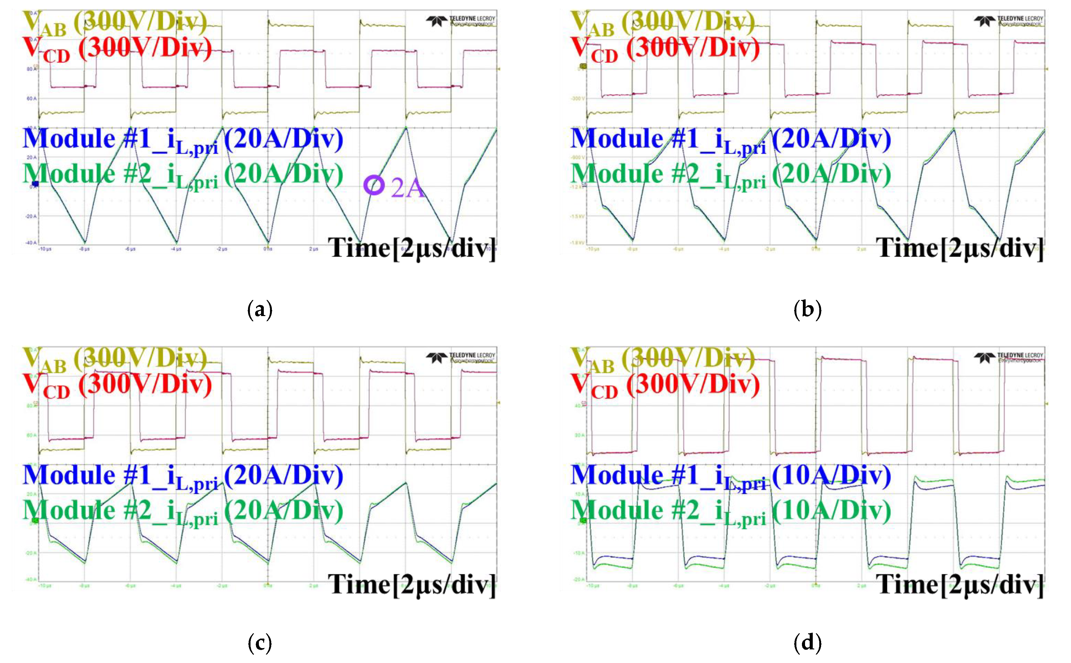
- Bare-Die SiC MOSFETs of 4 mm × 6 mm size were applied instead of a conventional packaged switch. The developed switch module has low switching loss and low oscillations due to its low parasitic composition, which can operate at high frequency.
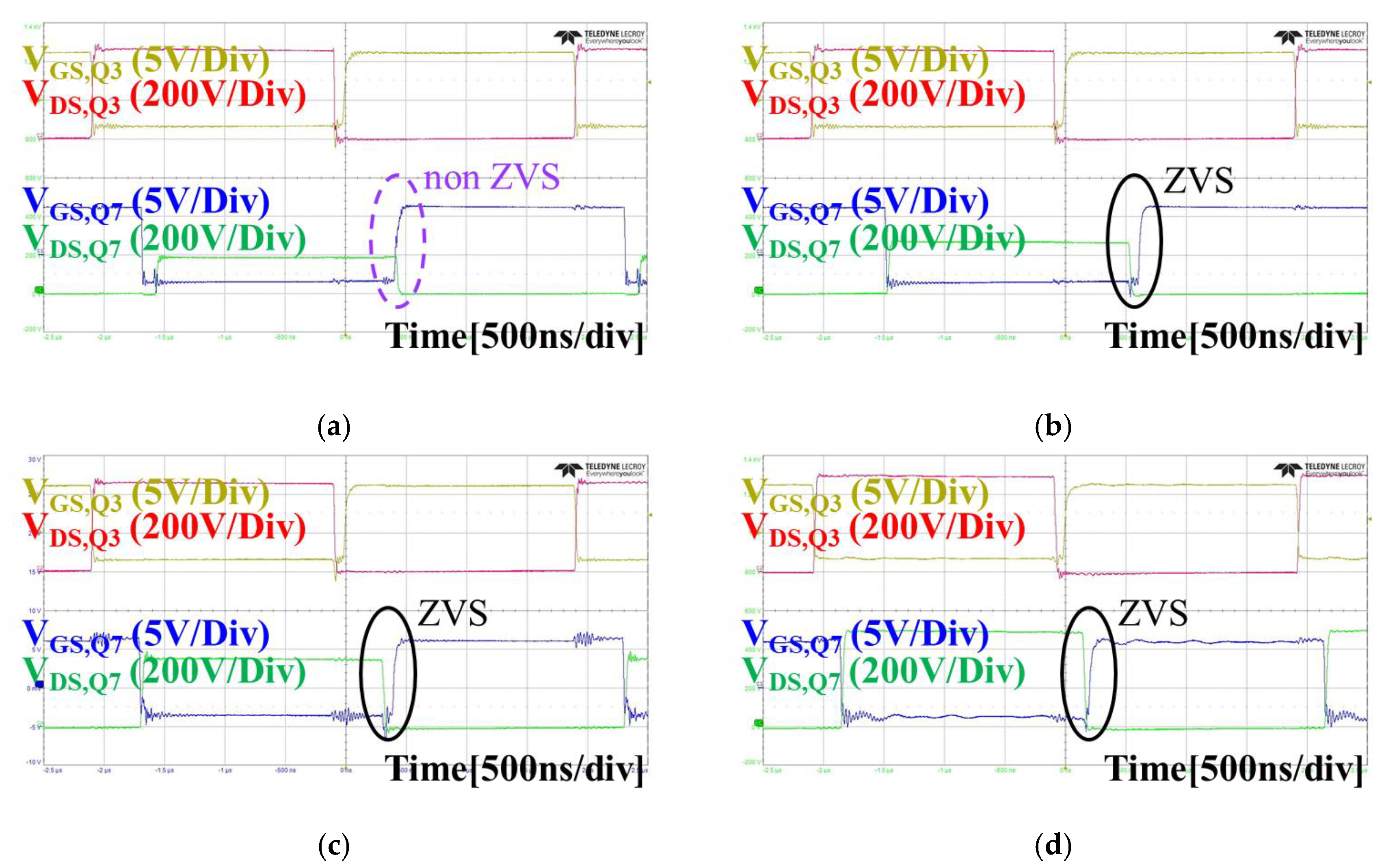
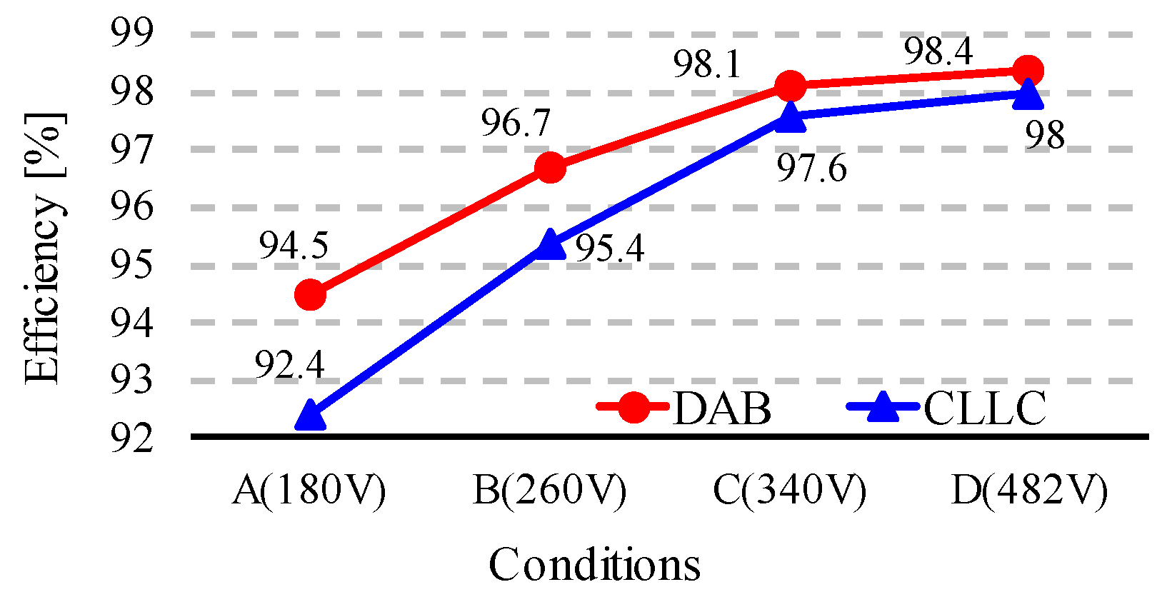
- The volume was reduced by using the leakage inductance of a planar transformer without using an additional inductor. Zero voltage switching (ZVS) was achieved in the battery voltage range of 250–380 V, and the final prototype had a power density of 5.44 kW/L. Using a DAB, up to 98% efficiency was satisfied in the constant power (CP) section.
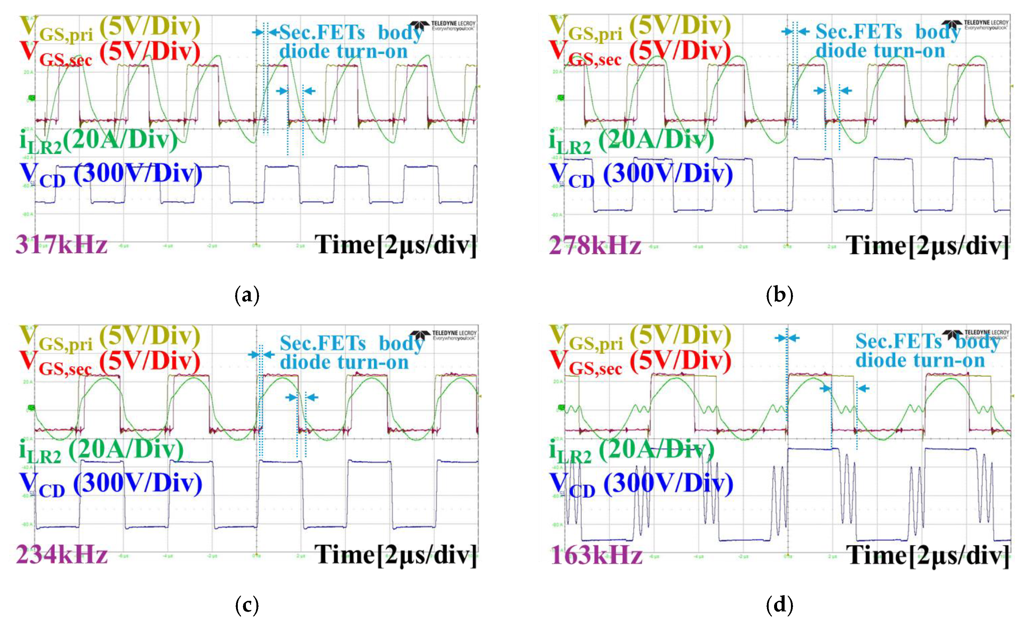
- Loss reduction was produced through soft switching and synchronous rectification (SR). Through SR driving, the efficiency increased by up to 1.7%.
- An integrated transformer using leakage inductance was proposed. As a result, efficiencies of 97.5% and 97.3% were satisfied in grid to vehicle (G2V) and V2G.
2. Operation Principles
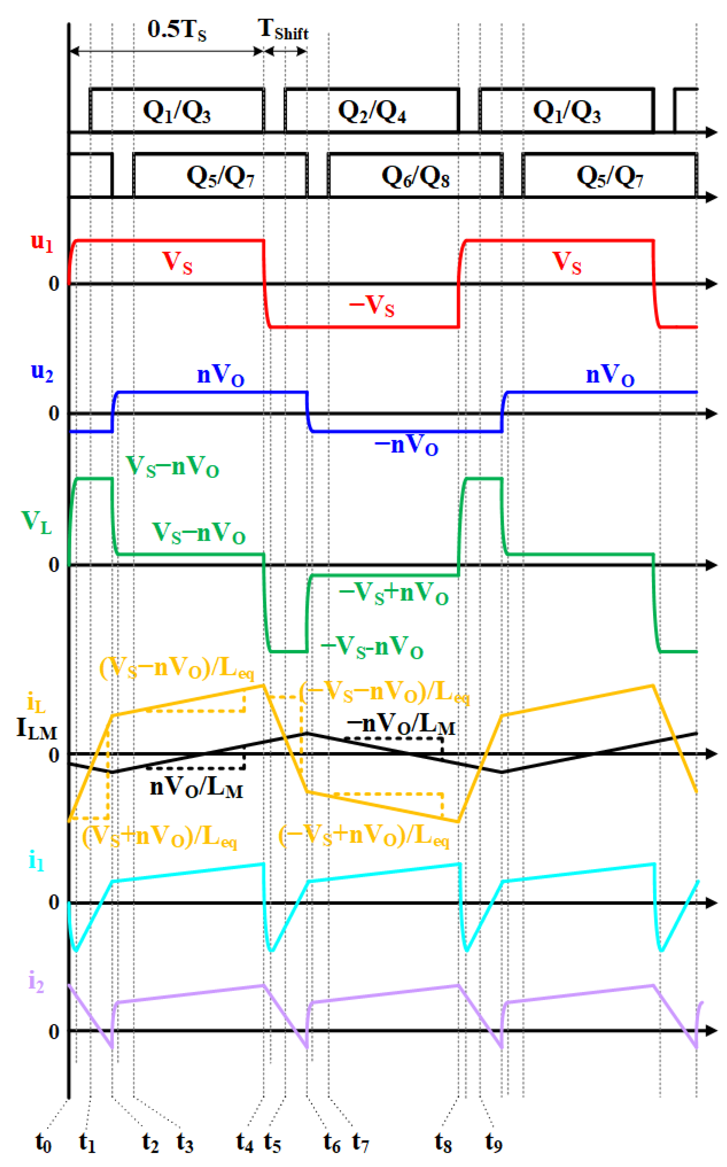
2.1. DAB Converter
- The input and output voltage , is constant.
- The output capacitance is very large.
- The magnetizing inductance is significantly larger than the .
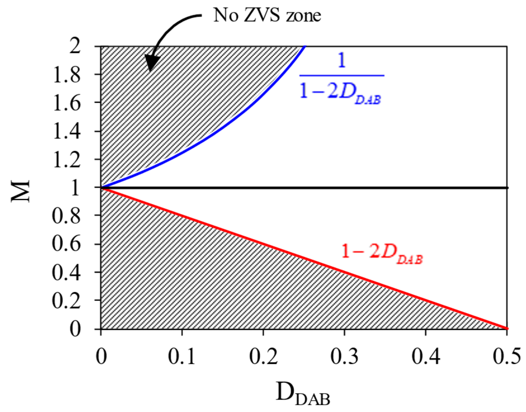
- The duty cycle of the DAB is denoted as and is defined as .
- The range of is 0 to 0.5.
2.2. CLLC Converter
- The input and output voltage , is constant.
- The output capacitance is very large.
- Instead of secondary side FETs switching, operation relies on the body diode, which is considered ideal.
2.3. Comparison in Operation Principle
3. Design Considerations
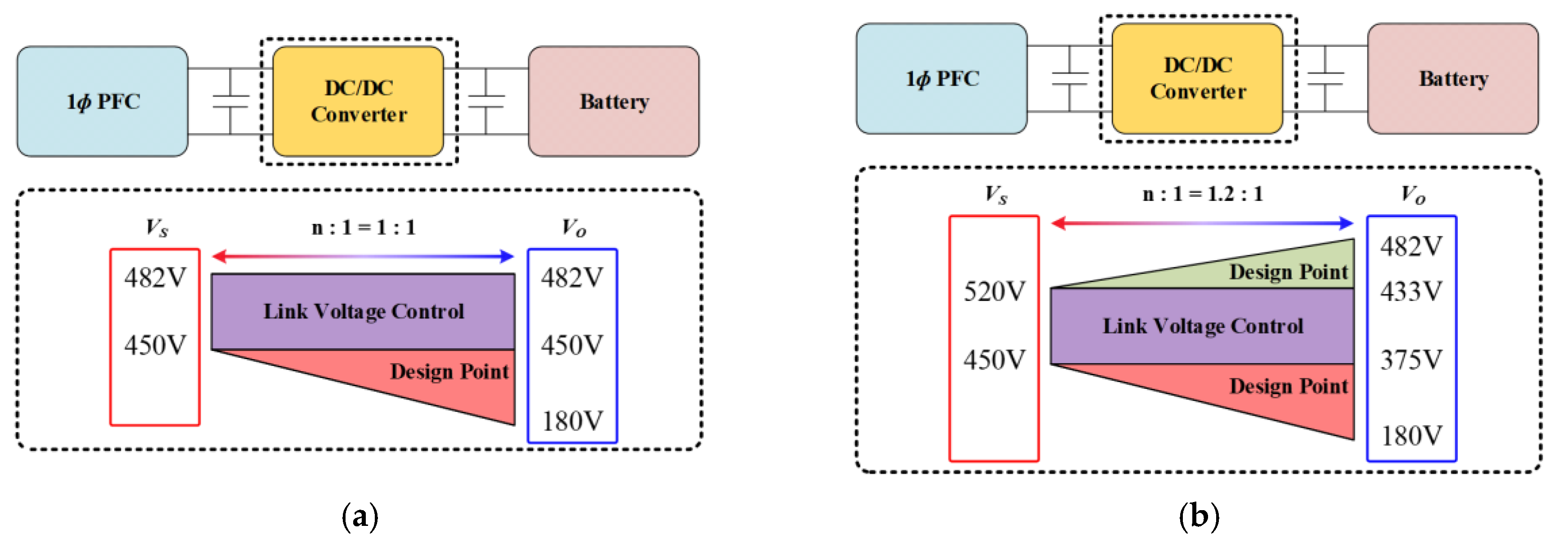
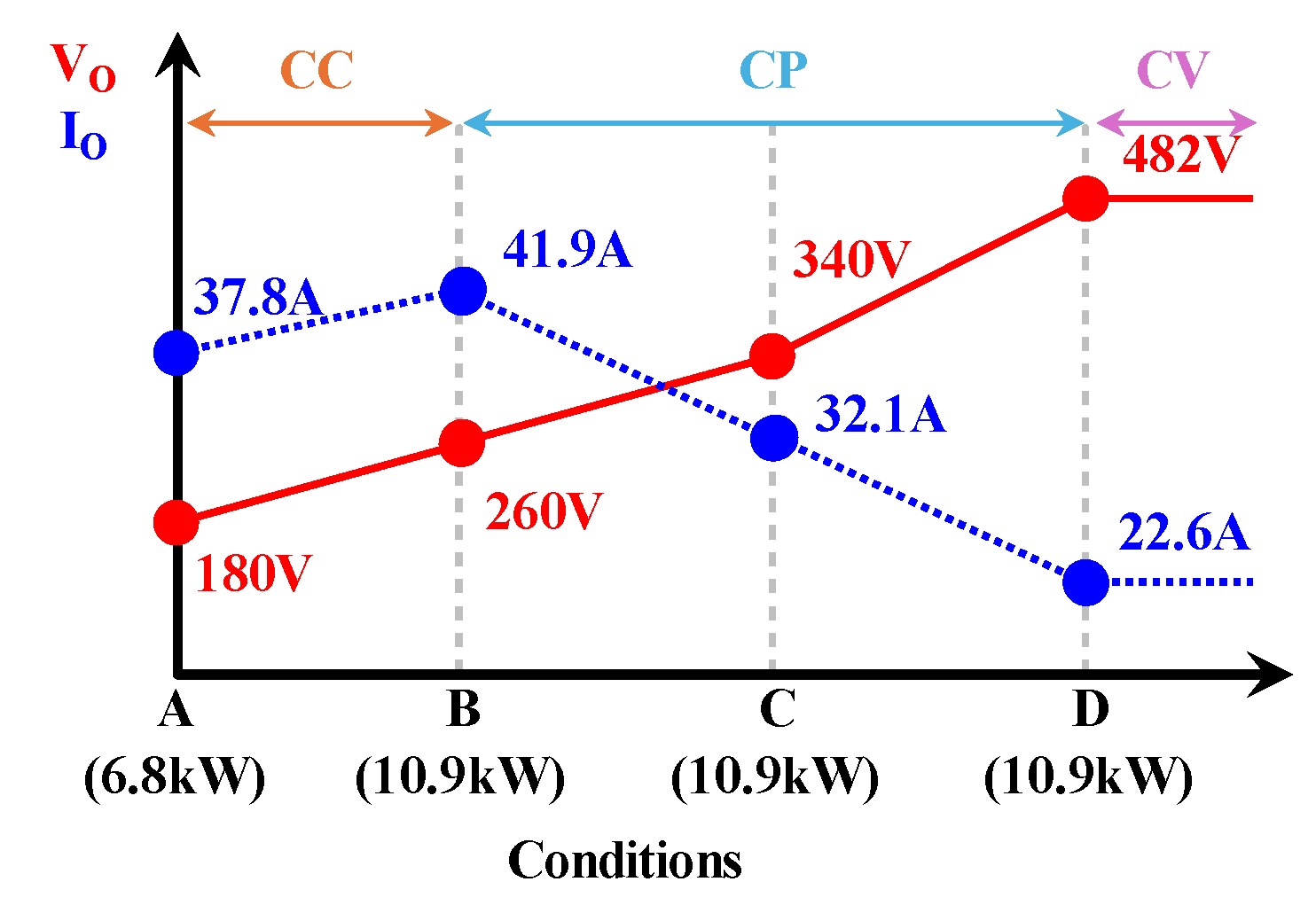
3.1. Design Direction—Design Parameters
3.2. Design Direction About Transformer
4. Experimental Results
5. Analysis of Experimental Results
5.1. Switch Loss
5.2. DCX Loss
5.3. Differences in Control and Comprehensive Analysis
6. Conclusions
Author Contributions
Funding
Data Availability Statement
Conflicts of Interest
References
- Ringwood, J.V.; Bacelli, G.; Fusco, F. Energy-Maximizing Control of Wave-Energy Converters: The Development of Control System Technology to Optimize Their Operation. IEEE Control. Syst. Mag. 2014, 34, 30–55. [Google Scholar]
- Lee, H.; Romero, J. Climate Change 2023: Synthesis Report; IPCC: Geneva, Switzerland, 2024; pp. 1–34. [Google Scholar]
- Khaligh, A.; Dusmez, S. Comprehensive Topological Analysis of Conductive and Inductive Charging Solutions for Plug-In Electric Vehicles. IEEE Trans. Veh. Technol. 2012, 61, 3475–3489. [Google Scholar] [CrossRef]
- Gupta, A.; Sisodia, S. BEV On-Board Charger Market—By Rating (<11 kW, >11 kW to 22 kW, >22 kW), By Current (AC, DC), & Forecast, 2023–2032, Sample Report; Global Market Insight: Selbyville, DE, USA, 2023. [Google Scholar]
- COP28. Available online: https://www.cop28.com/en/global-renewables-and-energy-efficiency-pledge (accessed on 27 August 2024).
- UNECE. Available online: https://unece.org/climate-change/press/cop28-unece-and-partners-highlight-need-decarbonize-inland-transport-and-how (accessed on 28 August 2024).
- Patil, D.; Agarwal, V. Compact Onboard Single-Phase EV Battery Charger with Novel Low-Frequency Ripple Compensator and Optimum Filter Design. IEEE Trans. Veh. Technol. 2016, 65, 1948–1956. [Google Scholar] [CrossRef]
- Yilmaz, M.; Krein, P.T. Review of Battery Charger Topologies, Charging Power Levels, and Infrastructure for Plug-In Electric and Hybrid Vehicles. IEEE Trans. Power Electron. 2013, 28, 2151–2169. [Google Scholar] [CrossRef]
- Tu, H.; Feng, H.; Srdic, S.; Lukic, S. Extreme Fast Charging of Electric Vehicles: A Technology Overview. IEEE Trans. Transp. Electrif. 2019, 5, 861–878. [Google Scholar] [CrossRef]
- Manzetti, S.; Mariasiu, F. Electric vehicle battery technologies: From present state to future systems. Renew. Sustain. Energy Rev. 2015, 51, 1004–1012. [Google Scholar] [CrossRef]
- Williamson, S.S.; Rathore, A.K.; Musavi, F. Industrial Electronics for Electric Transportation: Current State-of-the-Art and Future Challenges. IEEE Trans. Ind. Electron. 2015, 62, 3021–3032. [Google Scholar] [CrossRef]
- Khaligh, A.; D’Antonio, M. Global Trends in High-Power On-Board Chargers for Electric Vehicles. IEEE Trans. Veh. Technol. 2019, 68, 3306–3324. [Google Scholar] [CrossRef]
- Liu, Z.; Li, B.; Lee, F.C.; Li, Q. High-Efficiency High-Density Critical Mode Rectifier/Inverter for WBG-Device-Based On-Board Charger. IEEE Trans. Ind. Electron. 2017, 64, 9114–9123. [Google Scholar] [CrossRef]
- Karneddi, H.; Ronanki, D. Universal Bridgeless Nonisolated Battery Charger with Wide-Output Voltage Range. IEEE Trans. Power Electron. 2023, 38, 2816–2820. [Google Scholar] [CrossRef]
- Oh, C.-Y.; Kim, D.-H.; Woo, D.-G.; Sung, W.-Y.; Kim, Y.-S.; Lee, B.-K. A High-Efficient Nonisolated Single-Stage On-Board Battery Charger for Electric Vehicles. IEEE Trans. Power Electron. 2013, 28, 5746–5757. [Google Scholar] [CrossRef]
- Lee, I.-O. Hybrid PWM-Resonant Converter for Electric Vehicle On-Board Battery Chargers. IEEE Trans. Power Electron. 2016, 31, 3639–3649. [Google Scholar] [CrossRef]
- Lee, I.-O.; Moon, G.-W. Half-Bridge Integrated ZVS Full-Bridge Converter with Reduced Conduction Loss for Electric Vehicle Battery Chargers. IEEE Trans. Ind. Electron. 2014, 61, 3978–3988. [Google Scholar] [CrossRef]
- Whitaker, B.; Barkley, A.; Cole, Z.; Passmore, B.; Martin, D.; McNutt, T.R.; Lostetter, A.B.; Lee, J.S.; Shiozaki, K. A High-Density, High-Efficiency, Isolated On-Board Vehicle Battery Charger Utilizing Silicon Carbide Power Devices. IEEE Trans. Power Electron. 2014, 29, 2606–2617. [Google Scholar] [CrossRef]
- Gu, B.; Lai, J.-S.; Kees, N.; Zheng, C. Hybrid-Switching Full-Bridge DC–DC Converter with Minimal Voltage Stress of Bridge Rectifier, Reduced Circulating Losses, and Filter Requirement for Electric Vehicle Battery Chargers. IEEE Trans. Power Electron. 2013, 28, 1132–1144. [Google Scholar] [CrossRef]
- Shafiei, N.; Ordonez, M.; Craciun, M.; Botting, C.; Edington, M. Burst Mode Elimination in High-Power LLC Resonant Battery Charger for Electric Vehicles. IEEE Trans. Power Electron. 2016, 31, 1173–1188. [Google Scholar] [CrossRef]
- Vu, V.-B.; Tran, D.-H.; Choi, W. Implementation of the Constant Current and Constant Voltage Charge of Inductive Power Transfer Systems With the Double-Sided LCC Compensation Topology for Electric Vehicle Battery Charge Applications. IEEE Trans. Power Electron. 2018, 33, 7398–7410. [Google Scholar] [CrossRef]
- Li, W.; Zhao, H.; Li, S.; Deng, J.; Kan, T.; Mi, C.C. Integrated LCC Compensation Topology for Wireless Charger in Electric and Plug-in Electric Vehicles. IEEE Trans. Ind. Electron. 2015, 62, 4215–4225. [Google Scholar] [CrossRef]
- Yu, G.; Choi, S. An Effective Integration of APM and OBC With Simultaneous Operation and Entire ZVS Range for Electric Vehicle. IEEE Trans. Power Electron. 2021, 36, 10343–10354. [Google Scholar] [CrossRef]
- Kim, Y.-S.; Oh, C.-Y.; Sung, W.-Y.; Lee, B.K. Topology and Control Scheme of OBC–LDC Integrated Power Unit for Electric Vehicles. IEEE Trans. Power Electron. 2017, 32, 1731–1743. [Google Scholar] [CrossRef]
- Lee, D.-W.; Lee, B.-S.; Ahn, J.-H.; Kim, J.-Y.; Kim, J.-K. New Combined OBC and LDC System for Electric Vehicles With 800 V Battery. IEEE Trans. Ind. Electron. 2022, 69, 9938–9951. [Google Scholar] [CrossRef]
- Park, Y.; Chakraborty, S.; Khaligh, A. DAB Converter for EV Onboard Chargers Using Bare-Die SiC MOSFETs and Leakage-Integrated Planar Transformer. IEEE Trans. Transp. Electrif. 2022, 8, 209–224. [Google Scholar] [CrossRef]
- Nguyen, D.-D.; Fujita, G.; Bui-Dang, Q.; Ta, M.C. Reduced-Order Observer-Based Control System for Dual-Active-Bridge DC/DC Converter. IEEE Trans. Ind. Appl. 2018, 54, 3426–3439. [Google Scholar] [CrossRef]
- Zou, S.; Lu, J.; Mallik, A.; Khaligh, A. Bi-Directional CLLC Converter With Synchronous Rectification for Plug-In Electric Vehicles. IEEE Trans. Ind. Appl. 2018, 54, 998–1005. [Google Scholar] [CrossRef]
- Yuan, T.; Jin, F.; Li, Q. Analysis and Comparison of Integrated Planar Transformers for 22-kW On-Board Chargers. IEEE Trans. Power Electron. 2024, 39, 11368–11385. [Google Scholar] [CrossRef]
- He, P.; Khaligh, A. Comprehensive Analyses and Comparison of 1 kW Isolated DC–DC Converters for Bidirectional EV Charging Systems. IEEE Trans. Transp. Electrif. 2017, 3, 147–156. [Google Scholar] [CrossRef]
- Jung, J.-H.; Kim, H.-S.; Ryu, M.-H.; Baek, J.-W. Design Methodology of Bidirectional CLLC Resonant Converter for High-Frequency Isolation of DC Distribution Systems. IEEE Trans. Power Electron. 2013, 28, 1741–1755. [Google Scholar] [CrossRef]
- Oggier, G.G.; Garcia, G.O.; Oliva, A.R. Modulation strategy to operate the dual active bridge DC-DC converter under soft switching in the whole operating range. IEEE Trans. Power Electron. 2011, 26, 1228–1236. [Google Scholar] [CrossRef]
- Zhao, B.; Song, Q.; Liu, W. Power Characterization of Isolated Bidirectional Dual-Active-Bridge DC–DC Converter With Dual-Phase-Shift Control. IEEE Trans. Power Electron. 2012, 27, 4172–4176. [Google Scholar] [CrossRef]
- Huang, J.; Wang, Y.; Li, Z.; Lei, W. Unified Triple-Phase-Shift Control to Minimize Current Stress and Achieve Full Soft-Switching of Isolated Bidirectional DC–DC Converter. IEEE Trans. Ind. Electron. 2016, 63, 4169–4179. [Google Scholar] [CrossRef]
- Wu, F.; Feng, F.; Gooi, H.B. Cooperative Triple-Phase-Shift Control for Isolated DAB DC–DC Converter to Improve Current Characteristics. IEEE Trans. Ind. Electron. 2019, 66, 7022–7031. [Google Scholar] [CrossRef]
- Zhao, S.; Li, Q.; Lee, F.C.; Li, B. High-frequency transformer design for modular power conversion from medium-voltage AC to 400 VDC. IEEE Trans. Power Electron. 2018, 33, 7545–7557. [Google Scholar] [CrossRef]
- Cao, Y.; Ngo, M.; Burgos, R.; Ismail, A.; Dong, D. Switching Transition Analysis and Optimization for Bidirectional CLLC Resonant DC Transformer. IEEE Trans. Power Electron. 2022, 37, 3786–3800. [Google Scholar] [CrossRef]
- Zhao, C.; Jin, F.; Li, Z.; Hsieh, Y.-H.; Lee, F.C.; Li, Q. Design Consideration for CLLC Converter with High Power and Wide Gain Range. In Proceedings of the 2023 IEEE Applied Power Electronics Conference and Exposition (APEC), Orlando, FL, USA, 19–23 March 2023; pp. 1–6. [Google Scholar]
- Zhang, Z.; Liu, C.; Si, Y.; Liu, Y.; Lei, Q. Investigation of Adaptive Synchronous Rectifier (SR) Driving Scheme for LLC/CLLC Resonant Converter in EV On-Board Chargers. In Proceedings of the 2020 IEEE Applied Power Electronics Conference and Exposition (APEC), New Orleans, LA, USA, 15–19 March 2020; pp. 2185–2191. [Google Scholar]
- Chen, N.; Chen, M.; Li, B.; Wang, X.; Sun, X.; Zhang, D. Synchronous Rectification Based on Resonant Inductor Voltage for CLLC Bidirectional Converter. IEEE Trans. Power Electron. 2022, 37, 547–561. [Google Scholar] [CrossRef]








| Item | DAB | CLLC |
|---|---|---|
| Number of components | A few | A lot |
| Design complexity | Low | High |
| Soft-switching range | Limited | Full |
| Modulation control | Phase shift | Frequency |
| Parameter | Value | Unit | Note |
|---|---|---|---|
| Rated Power | 10.9 | kW | - |
| Input Voltage Range | 450~520 | Vdc | - |
| Output Voltage Range | 180~482 | Vdc | - |
| Maximum Output Current | 41.9 | Arms | - |
| Charging Method | CC-CV | - | - |
| Target Efficiency | 97.5 | % | @Vo = 340 V |
| Product of GaNFET | GS66516B | - | - |
| Target Power Density | 5.5 | kW/L | Except for PFC |
| Item | Primary Side RMS in FETs | Secondary Side RMS in FETs | ZVS Achievement Of Secondary Side | |
|---|---|---|---|---|
| n ↑ | Decrease | Increase | Decrease | Toward bad |
| Leq ↓ | Decrease | Decrease | Decrease | Toward bad |
| fs ↓ | Decrease | Decrease | Decrease | Toward bad |
| Item | [μH] | [μH] | ||
|---|---|---|---|---|
| Figure 9 | ||||
| (a) | 1.2 | 4.54 | 7.7 | 35 |
| (b) | Constant (=1.2) | Constant (=4.54) | Twice (=15.4) | Twice (=70) |
| (c) | Constant (=1.2) | Low (=2.27) | Twice (=15.4) | Constant (=35) |
| (d) | Constant (=1.2) | High (=9.09) | Constant (=7.7) | Twice (=70) |
| (e) | Increased (=1.4) | Constant (=4.54) | Constant (=7.7) | Constant (=35) |
| Parameter | Value | Unit |
|---|---|---|
| 1 (9:9) | - | |
| 250 | kHz | |
| 9.6 | μH | |
| 0.318~0.125 | - |
| Parameter | Value | Unit |
|---|---|---|
| 1.2 (12:10) | - | |
| 200 | kHz | |
| 35 | μH | |
| 7.5 | μH | |
| 84 | nF | |
| Range of frequency | 160~307 | kHz |
| Parameter | Value | Unit |
|---|---|---|
| Core type | PQ6145 | - |
| Core material | PM16 | - |
| 491 | mm2 | |
| Litz wire | 0.04φ/3180 | - |
| 225.7 | μH | |
| Eq. Leakage inductance | 9.595 | μH |
| Parameter | Calculation | Simulation | Unit | Note. | |
|---|---|---|---|---|---|
| Bmax | 0.109 | 0.089 | T | = 482 V | |
| Core loss | 7.80 | 7.48 | W | ||
| Winding loss | DC | 1.60 | 1.33 | W | |
| Eddy | - | 14.13 | W | ||
| Bmax | 0.059 | 0.057 | T | = 260 V | |
| Core loss | 1.1 | 1.74 | W | ||
| Winding loss | DC | 5.60 | 5.12 | W | |
| Eddy | - | 24.26 | W | ||
| Parameter | Value | Unit |
|---|---|---|
| Core type | PQ6145 | - |
| Core material | PM16 | - |
| 491 | mm2 | |
| Litz wire | 0.04φ/3180 | - |
| 34.63 | μH | |
| 7.71 | μH | |
| 5.19 | μH |
| Parameter | Calculation | Simulation | Unit | Note. | |
|---|---|---|---|---|---|
| Bmax | 0.154 | 0.147 | T | = 482 V | |
| Core loss | 8.84 | 10.06 | W | ||
| Winding loss | DC | 2.75 | 2.55 | W | |
| Eddy | - | 7.41 | W | ||
| Bmax | 0.051 | 0.066 | T | = 260 V | |
| Core loss | 2.5 | 2.58 | W | ||
| Winding loss | DC | 6.61 | 5.49 | W | |
| Eddy | - | 34.49 | W | ||
| Parameter | Value | Unit | Note |
|---|---|---|---|
| Core type | PQ6145 | - | - |
| Core material | PM16 | - | - |
| 491 | mm2 | - | |
| Litz wire | 0.04φ/3180 | - | - |
| 213.5 | μH | In DAB | |
| 9.2 | μH | In DAB | |
| 39.03 | μH | In CLLC | |
| 5.85 | μH | In CLLC | |
| 6.86 | μH | In CLLC | |
| 108 | nF | In CLLC | |
| 92 | nF | In CLLC |
Disclaimer/Publisher’s Note: The statements, opinions and data contained in all publications are solely those of the individual author(s) and contributor(s) and not of MDPI and/or the editor(s). MDPI and/or the editor(s) disclaim responsibility for any injury to people or property resulting from any ideas, methods, instructions or products referred to in the content. |
© 2024 by the authors. Licensee MDPI, Basel, Switzerland. This article is an open access article distributed under the terms and conditions of the Creative Commons Attribution (CC BY) license (https://creativecommons.org/licenses/by/4.0/).
Share and Cite
Oh, H.-S.; Hong, S.-Y.; Lee, J.; Lee, J.-B. Comparison of Bi-Directional Topologies for On-Board Charger: A 10.9 kW High-Efficiency High Power Density of DC-DC Stage. Energies 2024, 17, 5496. https://doi.org/10.3390/en17215496
Oh H-S, Hong S-Y, Lee J, Lee J-B. Comparison of Bi-Directional Topologies for On-Board Charger: A 10.9 kW High-Efficiency High Power Density of DC-DC Stage. Energies. 2024; 17(21):5496. https://doi.org/10.3390/en17215496
Chicago/Turabian StyleOh, Hyeong-Seok, Seong-Yong Hong, Ju Lee, and Jae-Bum Lee. 2024. "Comparison of Bi-Directional Topologies for On-Board Charger: A 10.9 kW High-Efficiency High Power Density of DC-DC Stage" Energies 17, no. 21: 5496. https://doi.org/10.3390/en17215496
APA StyleOh, H.-S., Hong, S.-Y., Lee, J., & Lee, J.-B. (2024). Comparison of Bi-Directional Topologies for On-Board Charger: A 10.9 kW High-Efficiency High Power Density of DC-DC Stage. Energies, 17(21), 5496. https://doi.org/10.3390/en17215496


