Article

Suppression of Metal Particles by Coating for a ±550 kV DC GIS

1
Department of Electrical Engineering, Tsinghua University, Beijing 100084, China
2
Xinjiang Electric Power Research Institute, State Grid, Urumqi 830011, China
3
Department of Electrical Engineering, Hebei University of Technology, Tianjin 300401, China
*
Authors to whom correspondence should be addressed.
Energies 2024, 17(22), 5627; https://doi.org/10.3390/en17225627
Submission received: 29 September 2024 / Revised: 20 October 2024 / Accepted: 6 November 2024 / Published: 11 November 2024
(This article belongs to the Special Issue Power Electronics Technology and Application)

Abstract

:
Coating the inner surface of grounded enclosures has been used to inhibit metal particle motion inside AC GIS for many years. However, for DC GIS, only fundamental research has been performed, while very few attempts have been made on real DC GIS. This paper reviews the basic research into the inhibition of metal particles by coating at DC. On this basis, based on a ±550 kV DC GIS busbar, an inhibition test of metal particle motion using coating was performed. Four types of metal particles were used as samples to verify the inhibitory effect of the grounded enclosure coating. The results showed that the coating has a very good inhibitory effect on block and powder metal particles on real GIS, and there are rarely any metal particles moving again under the rated DC voltage. However, for wire and flake metal particles, the effectiveness of the coating depends on the way the particle contacts the ground electrode when they are still, and ~30% of wire and flake metal particles can be inhibited. The conclusion of this paper is of guiding significance for the research and development of stable and reliable DC gas-insulated equipment.

1. Introduction

With the rapid advancements in gas insulation technology, GIS (Gas-Insulated Switchgear) and GIL (Gas-Insulated Lines) have seen widespread use and extensive research into power transmission and transformation systems due to their high transmission capacity, strong resistance to interference, compact footprint, and environmental benefits [1,2]. However, factors such as inadequate cleaning, mechanical collisions, and thermal expansion and contraction can lead to the generation of metal particles within the GIS/GIL [3,4]. These metal particles create highly uneven electric fields, resulting in significant field distortions. Moreover, as the particles move toward areas of high electric field intensity, they can induce localized discharges or arcs. Additionally, metal particles that are in close proximity to basin insulators may become adhered to the surface under Coulomb force, introducing substantial charge and potentially causing surface flashover failures of the insulator [5,6]. It has been reported that between 2010 and 2020, insulation failures caused by metal particles accounted for as much as 50% of total failures in China [7].
From the perspective of metal particle suppression, several strategies have been proposed, including particle traps, coatings on the inner walls of enclosures, pre-embedded electrodes in insulators, and driving electrodes. There are relatively mature products for particle traps under AC, but metal particles move violently under DC and are very likely to escape [8,9]. Pre-embedded electrodes in insulators can reduce the lifting field strength of nearby metal particles by about 5%. Pre-embedded electrodes in insulators can reduce the electric field strength near metal particles by approximately 5%; however, the integration of electrodes into the insulator during manufacturing makes installation, maintenance, and replacement exceedingly difficult [10,11]. Driving electrodes, which rely on the principle of rebound from collisions, can cause metal particles to move axially away from the insulator region, but this method lacks effectiveness in actually suppressing particle movement and offers limited efficacy in curbing particle activity [12,13]. In contrast, coatings significantly enhance the take-off field strength of metal particles through adsorption. Electrode films can be directly applied to existing equipment, offering a more convenient and rapid solution with substantial potential for further development and application when compared with other technologies [14,15].
This paper reviews the current research progress on coatings aimed at inhibiting metal particle movement. Additionally, it systematically analyzes the effects of coatings on different types of metal particles using a ±550 kV metal particle dynamics observation platform. The findings of this research hold both theoretical and practical significance in developing effective strategies for suppressing metal particle activity and enhancing the stability and safety of high-voltage equipment.

2. Literature Review on Metal Particle Suppression Using Coating Technique

2.1. Basic Theory

When performing dynamic analysis of metal particles, it is essential to identify their types and charging characteristics. In GIS/GIL systems, metal particles typically appear in the form of blocks, wires, flakes, or powder. The primary charging mechanisms include conductive charging, tip corona discharge, and micro-discharges between the metal particles and electrodes.
The charge carried by metal particles is closely related to their shape, size, and the electric field distribution in the surrounding environment. In 1962, Lebedev N. N et al. took the lead in studying the charging characteristics of spherical metal particles. By solving partial differential equations in the electrostatic field region between flat electrodes, they determined the charge of spherical metal particles [16]. Subsequently, Sakai K. I. et al. discovered that the charge of wire particles depends on their position and morphology and derived charging formulas for wire metal particles in both flat and vertical orientations [17]. Khan Y et al. extended this research by calculating the charge of flaky particles using a rotating ellipsoid model [18]. Li Qingmin et al. introduced two modes of charging, diffusion and field-induced, and determined the charge characteristics of powdery particles [19,20]. Additionally, Li Chengrong et al. compared metal particles under the same conditions and found that flaky particles carry more charge than wire ones, making them more prone to inducing local discharges [21].
The force conditions of metal particles after being charged are different, and their movement characteristics inside GIS/GIL are also different. Anis H et al. studied the movement law of spherical metal particles under a non-uniform electric field and derived the calculation formula for critical lifting voltage [22]. Wang Jian et al. studied the force form of spherical metal particles and gave the gas resistance formula applicable to coaxial cylindrical electrodes under DC electric field by comparing Reynolds number [23]. Jia Jiangbo et al. proposed that the rolling friction coefficient should be used instead of the sliding friction coefficient when calculating spherical metal particles [24]. Lin Xin et al. reviewed the motion characteristics of metal particles under DC conditions, identifying two scenarios: metal particles either remain stationary on the electrode surface or move within the air gap of the cavity. In the former case, the particles are subject to friction from the ground electrode, while in the latter, they experience viscous resistance from the insulating gas, both of which act in the opposite direction of the particle’s movement [25]. The main forces acting on metal particles are summarized in Figure 1 [26,27] and Table 1 [28].
Under DC voltage, where the electric field direction remains constant, charged metal particles exhibit heightened mobility. Once lifted, their movement often spans the entire gas-insulated gap. Sun Jixing et al. developed a motion model for metal particles between flat electrodes and used the restitution coefficient to describe the multiple collisions between metal particles and the electrodes. Their research demonstrated that larger metal particles with lower restitution coefficients have a reduced frequency of collisions with the electrodes [29]. Due to the presence of basin insulators, the electric field near these insulators has an axial component. To simulate the electric field distribution more accurately within the GIS/GIL cavity, Lu Fangcheng et al. used wedge-shaped electrodes to study the movement of metal particles. They found that spherical metal particles undergo three phases: rolling, jumping, and rebounding [30,31]. Subsequently, Jia Jiangbo et al. systematically studied the movement of metal particles on wedge electrodes and found that the applied voltage, initial position of the foreign object, electrode inclination, material, and random effects from impact reflection all influence the form and trajectory of metal particle movement. The shape of the insulator and the electrode angle also impact the initial movement voltage and amplitude of the metal particles [32,33].
Compared with spherical metal particles, the charge distribution in wire and flaky metal particles is significantly more uneven. Studies by Morcos M. M. et al. have demonstrated that wire-shaped particles exhibit the greatest ability to distort electric fields and, therefore, pose the most significant threat to the insulation performance of equipment [34,35]. Wei Wei et al. conducted research into this topic and found that in DC electric fields, wire and flaky metal particles exhibit a phenomenon known as “flying firefly motion.” This refers to the particles floating near the surface of high-voltage electrodes or moving in the opposite direction without making contact with the grounded electrode. As a result, these particles remain in areas of high electric field intensity, such as near the surface of high-voltage electrodes, for extended periods, which significantly weakens the electrical strength of GIS/GIL systems [36,37]. Zhang Qiaogen et al. further explained the “flying firefly motion” from the perspective of space charge, suggesting that this behavior is driven by partial discharges of particles in space, generating substantial amounts of space charge that heavily influence the flight behavior of particles [38]. Research by Li Qingmin et al. has shown that the movement pattern of wire and flake particles is related to voltage polarity. Under positive voltage, particles tend to produce ground electrode fireflies, while under negative voltage, particles tend to produce high-voltage conductor fireflies, and the positive firefly voltage is higher than the negative firefly voltage. This difference in positive and negative polarity may be related to the corona starting voltage of particles under different polarities [39,40].
The sizes of metal particles in GIL/GIS span from micrometers to millimeters. Among them, the most common ones are micro- and nano-sized powder particles. Iwabuchi H. et al. found that under DC voltage, micrometer-sized metallic aluminum particles can become adsorbed on insulator surfaces, suggesting that powdery particles are a primary cause of radial charge distribution on insulator surfaces [41]. Li Chengrong et al. demonstrated that the Coulomb attraction and van der Waals forces between powdery particles and the insulator surface are the key factors leading to particle adhesion and persistence on the surface [42]. Based on the motion characteristics of powdery particles, Li Qingmin et al. developed a force analysis model for powder foreign matter in a multi-physical field, suggesting that distorted electric field forces in the initial state drive powder accumulation, adsorption, and diffusion [19]. Lv Fangcheng et al. observed that under DC voltage, powdery particles exhibit a “sandstorm” movement pattern, in which particles undergo violent collisions in the powder cloud, easily leading to local discharges and air gap breakdowns [43].

2.2. Cases and Scenarios

Coating the inner walls of the GIS/GIL housing with an insulating medium can significantly increase the lifting voltage of metal particles and enhance the insulation strength of the gas gap. In 1985, Srivastava K. D. et al. first discovered that coating grounded electrodes can mitigate contamination by metal particles. Their findings indicated that after coating grounded electrodes, the lifting voltage of spherical metal particles could be increased by more than twofold [44].
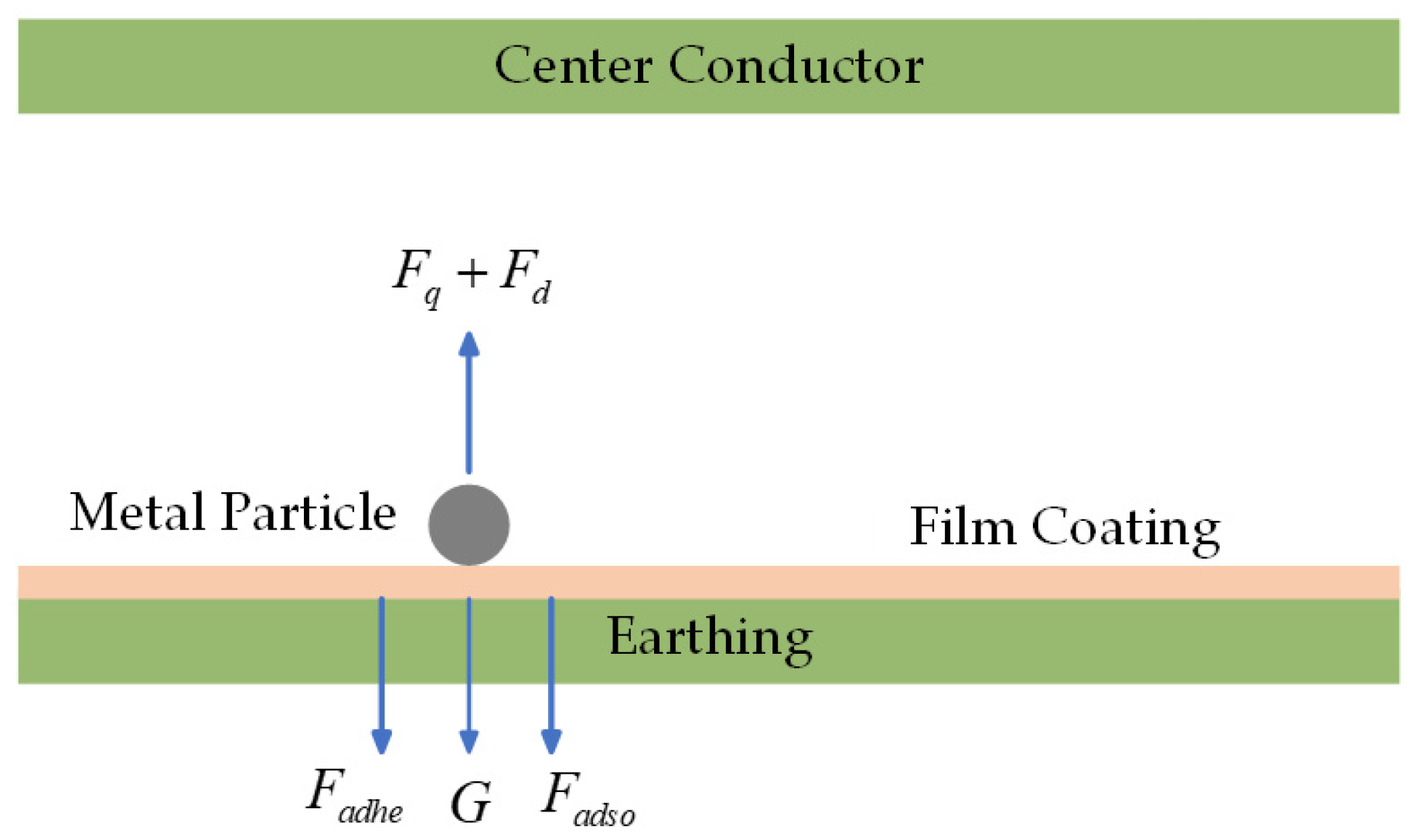
Regarding the mechanism by which coatings inhibit metal particles, Huang Xuwei et al. prepared a polyimide film containing a phenyl sulfide structure and observed that metal particles were adsorbed by the insulating film, effectively preventing the lifting of metal particles under DC voltage, as shown in Figure 2. The forces acting on the metal particles include the Coulomb force Fq, the electric field gradient force Fd, the electrostatic adsorption force Fadso between the charged particles and the film, the particle’s own gravity G, and the intrinsic adhesion force Fadhe between the particles and the film [45]. Lv Fangcheng et al. conducted a systematic study of the coating inhibition mechanism and found that when metal particles move on a bare electrode, the maximum electric field strength occurs at the top of the particle. However, when moving on a coated electrode, the maximum electric field strength shifts to the bottom of the particle. The study highlighted that the polarization force acting on the metal particles due to the coating is a key factor in suppressing their movement [46]. Additionally, Zhang Qiaogen et al. recorded the movement of metal particles and concluded that the charging mechanism of foreign metal particles after coating depends on the type of voltage. Under AC voltage, micro-discharge around the coated metal particles is the primary charging mode, while under DC voltage, the particles are mainly charged by conduction through the resistive properties of the coating material [47]. Zhang Zhousheng et al. identified three primary mechanisms by which coatings improve insulation strength: (1) the high resistivity of the dielectric film impedes the development of pre-discharge in the gas, thereby raising the breakdown voltage of the air gap; (2) the coating significantly increases the electric field strength required to lift metallic foreign particles from the inner surface of the GIS/GIL shell; (3) the coating substantially reduces the amount of charge conducted to the metallic foreign particles upon collision with the electrode, thereby reducing partial discharge between the metallic particles and the electrode [48].
Regarding the practical effect of coatings in suppressing metallic foreign particles, Wang Jian et al. found that the inhibitory effect of surface coatings on metallic foreign particles under positive DC voltage is slightly better than under negative DC voltage [49]. Ni Xiaoru et al. discovered that the charging of metallic foreign particles under DC voltage exhibits a time lag, with the time lag under negative polarity being 16% longer than under positive polarity. They concluded that coating measures should be applied to the grounded electrode under positive polarity, and double-coating measures should be considered under negative polarity [50]. Furthermore, Shao Tao et al. used atmospheric-pressure dielectric barrier discharge plasma to deposit a silicon dioxide film on a copper surface, which effectively increased the lifting voltage of metallic particles [51]. Zhang Zhousheng et al. systematically compared the inhibitory effects of four high-resistance materials, Teflon, 1032 K high-resistance paint, epoxy Marlin orange primer (EMOP), and iron red primer, on metal particles in flat electrodes. The results show that the particles do not jump when the field strength reaches 5 kV/mm. Teflon and iron red primer cannot meet the fast polarity reversal condition during the test. When the field strength is 2 kV/mm, the particles will jump during the rapid voltage polarity conversion process, while 1032 K high-resistance paint and epoxy Marin orange primer do not have this phenomenon [48].
In conclusion, coating is a convenient and reliable method for inhibiting the movement of metallic foreign particles. However, current research, which primarily focuses on the lifting field strength to evaluate the quality of coating materials, is limited to ideal laboratory conditions and may not fully reflect the effectiveness of metallic particle suppression in real-world GIS/GIL applications. To address these challenges, we directly applied coating to the interior of a 550 kV busbar and systematically studied the suppression of different types of metallic foreign particles.

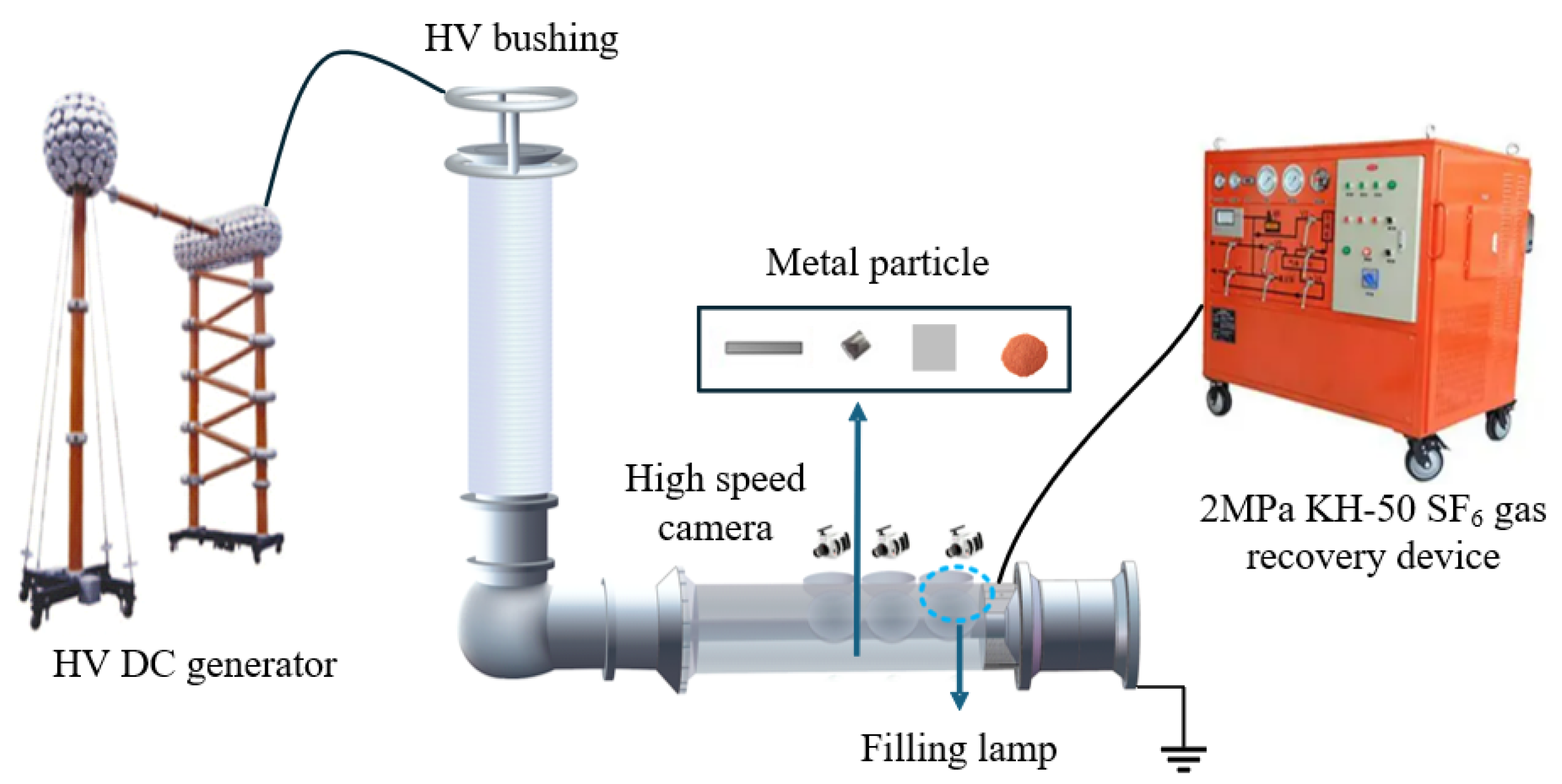
3. Experimental Setup

To evaluate the inhibitory effects of coatings on various types of metal particles, the ±550 kV GIS is utilized to construct a particle observation platform. The GIS cavity is equipped with six observation windows to enable real-time monitoring of particle behavior. A high-speed camera with a resolution of 1280 × 1024 pixels, a capture rate of 210 frames per second (fps), and an exposure time ranging from 16 μs to 1 s is used to capture the motion of the particles. A high-voltage direct current (HVDC) is introduced via the bushing end. The test particles include powder (10–100 μm), block particles (1 × 1 mm), wire particles (0.5 mm in diameter and 10 mm in length), and flake particles (0.05 mm thick, 5 × 5 mm in size), as illustrated in Figure 3.
The coating material selected is EMOP, with water-based epoxy resin as the base material, which exhibits relatively uniform and dense surface properties, performing well under conditions of high temperature, high pressure, and strong chemical corrosion. Studies have shown that EMOP can effectively suppress particle lift off and exhibits notable adsorption properties. It is capable of withstanding rapid polarity reversal conditions and has a shorter curing time compared with the 1032 K high-resistance coating [48]. Accordingly, four distinct coated environments were established to study particle motion under different conditions. These environments are defined as follows: (1) no coating on the conductor, coating on the inner wall; (2) coating on the conductor, no coating on the inner wall; (3) no coating on both the conductor and inner wall; (4) coating on both the conductor and inner wall (as shown in Figure 4). Additionally, the particle placement area is set to a width of 5 cm and a length of 10 cm. Through these four different coating configurations, the motion characteristics of metal particles can be comprehensively investigated.
Through earlier experiments, it was discovered that metal particles are more prone to takeoff under negative voltage. Therefore, to verify the suppression effect of the coating, a negative voltage is applied in all subsequent experiments. The experimental process proceeds as follows: metal particles are placed in the designated positions within the GIS, after which the casing is sealed, evacuated, and filled with SF6 gas at a pressure of 0.4 MPa. To ensure accurate measurement data, each pressurization duration is set to 5 min, with the voltage gradually increased to −550 kV over a 10 min period. An industrial camera records the motion of metal particles within the GIS during the test. Following voltage application, the pressure is rapidly reduced, and the SF6 gas is recovered, marking the completion of one test.

4. Impact Coating Test Results Based on a ±550 kV GIS Busbar

4.1. Powdery Particles

The powdery particles began to lift off at −291.8 kV, as observed from the front observation port, where it is evident that the powdery particles moved in a sector-shaped area with the conductor center as the circle center and the shell as the circular edge, with an included angle of about 16° (depending on the range of powder placement). There is a tendency for the sector area to expand. Once the powder moved onto the membrane, its movement rapidly diminished, eventually covering an area on the membrane that accounted for approximately 50° of the circumference around the circle centered on the conductor, as shown in Figure 5. From the onset of motion to nearing the end, the duration is 10 s, at which point the voltage is −322.2 kV. The motion process is shown in Figure 6, and the red mark indicates the state of the metal particles.
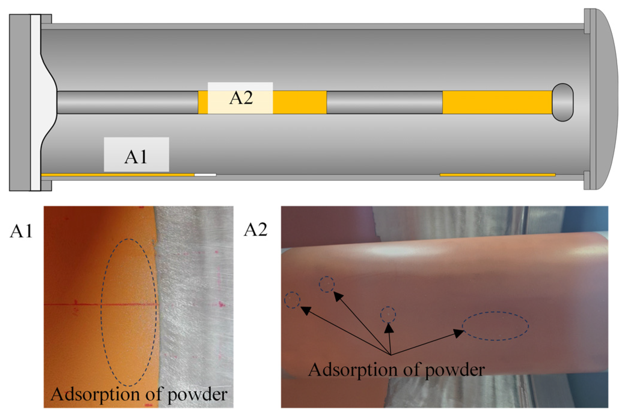
After the test, no adsorbed metal powder is observed on the basin insulator. The powder is concentrated in the A1 and A2 areas, marked by dotted circles, as shown in Figure 7. No obvious powder aggregation is found in the other locations by wiping. The powder is extremely easy to be adsorbed onto the nearby membrane, where it ceased movement. This is because the presence of the coating inhibits the charge exchange between the powder and the GIS enclosure, increasing the powder’s take-off field strength. Moreover, a relatively strong adsorption force exists between the coating and powder, causing the power to adhere firmly to the insulating film. This is quite consistent with the initial expectation, indicating that the epoxy Marlin orange primer has an excellent inhibitory effect on the motion of powdery particles.

4.2. Block Particles

The block particles started to jump at −399.1 kV. Figure 8 illustrates the motion process of the block particles, with their state highlighted in red. Figure 9 displays the motion trajectory of the block particles, represented by the red lines. The movement lasted for 70 s, at which time the voltage was −520.4 kV, after which most of the particles were adsorbed on the membrane.
The motion states of block-shaped particles after moving onto the membrane can be divided into three categories:
(a)
Particles that land in the lower region of the membrane (defined as the area on the circle centered on the conductor and bounded by the shell inner wall, with the vertically downward direction as the symmetry line of the sector, within an included angle of 80° and below), and do not collide with other particles, quickly cease bouncing, rolling only a short distance before coming to rest on the surface of the membrane.
(b)
Particles that land in the lower region of the membrane and collide with other particles, which easily causes the other particles to lift off.
(c)
Particles that land in the upper region of the membrane (above 80°) tend to slide down along the inner wall of the shell while moving vertically downward toward the conductor. When moving close to directly below the conductor, they move toward the direction of the conductor, almost without direct contact with the membrane surface, until colliding with the conductor. After bouncing downward, if they do not collide with other particles, they come to rest on the surface of the membrane.
After the experiment, no adsorbed block-shaped metal particles are observed on the basin insulator, and the specific distribution is shown in Figure 10. After the voltage increase, the vast majority (90.33%) of particles are adsorbed in the four coated areas (indicated by the yellow parts), and almost no block-shaped metals fall during the steady voltage phase. On the membrane, there are several densely populated areas, and this distribution pattern is related to the step length of each particle’s advancement.

4.3. Wire Particles

Wire particles are observed to lift off at a voltage of −318.7 kV. The motion of these particles on the grounded plate coated with the film can be categorized into four distinct states:
(a)
Stationary particles on the coated surface: Wire particles initially located on the film do not exhibit motion during the pressurization process and remain stationary until the end of pressurization. This behavior is shown in Figure 11, where the green markers indicate the particle positions.
(b)
Tangential movement and immobilization: In some cases, wire particles that initially move during pressurization subsequently travel onto the coated surface in a direction nearly tangential to the shell’s inner wall. Once these particles make contact with the coating, they quickly cease motion and remain immobilized for the remainder of the pressurization process. This behavior is represented in Figure 11 with red markers, demonstrating the coating’s ability to inhibit particle movement upon contact.
(c)
Perpendicular movement and reactivation: Wire particles that move upon touching the film in a direction nearly perpendicular to the tangent of the shell inner wall either stand on the film or move near it. As pressurization continued, they re-enter motion toward the conductor and then lift off, a process that could occur at any stage of pressurization without a specific voltage value associated.
(d)
Axial movement along the conductor: After most wire particles lift off, they move back and forth along the axial direction of the conductor. When reaching the boundary between the coated and uncoated sections of the conductor, their motion state hardly changes, as indicated by the red markers in Figure 12. At the tips of some particles, tiny discharges with the conductor are observable by the naked eye.
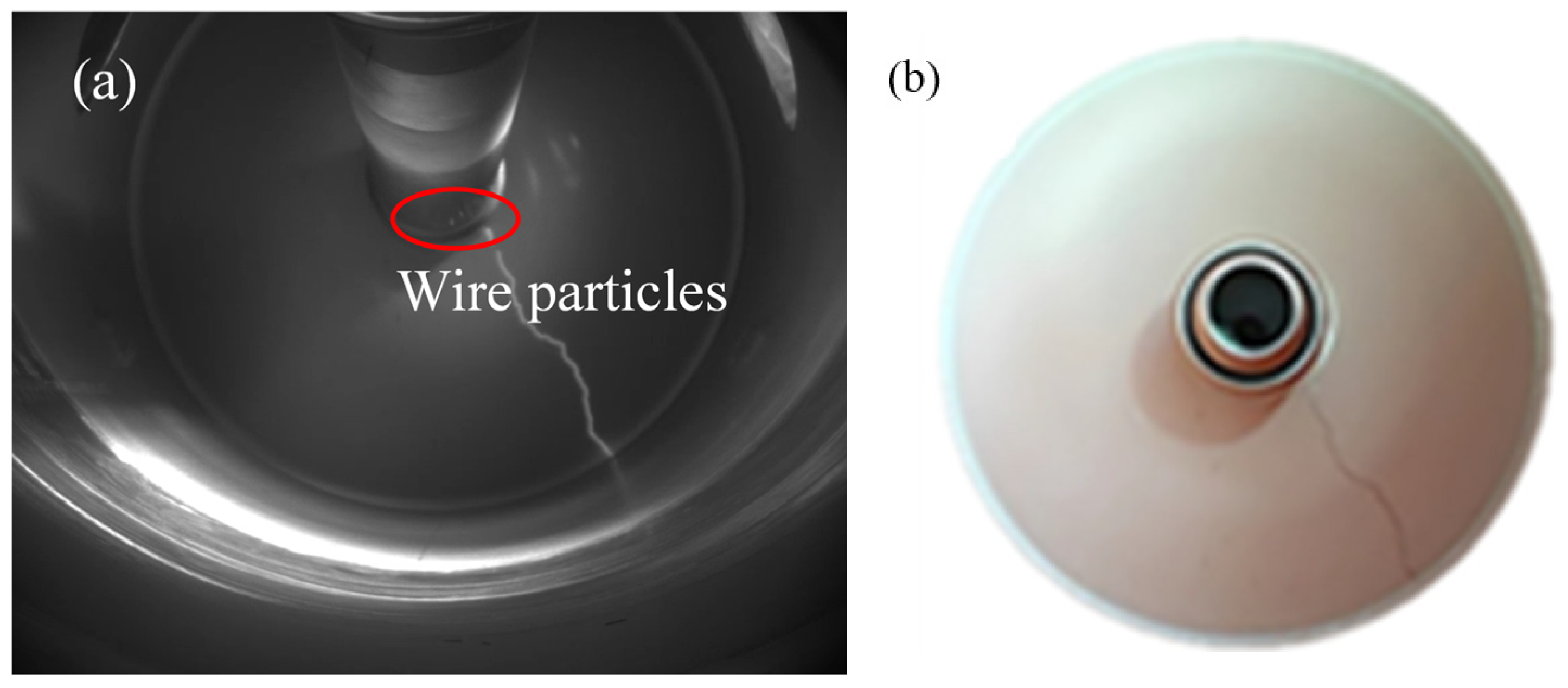
After the experiment, the final distribution of wire particles is unpredictable. Particles are found in both the coated and uncoated regions of the inner wall. The coating can only restrain wire particles that are initially at rest on the film and those that move onto the film after takeoff and are in full contact with it. It has no inhibitory effect on the particles that move like fireflies along the conductor. This is related to the contact angle between the metal particles and the film. When the two are completely attached, the overall adsorption force on the wire particles is the largest, and the charge on the tip of the particles is the smallest. Additionally, wire particles are observed to be adsorbed on the basin insulator, where they cause flashover, as shown in Figure 13. In this figure, the red markings represent wire particles moving along the conductor. The flashover traces exhibit intermittent intervals corresponding to the length of the particles. The reason for this phenomenon is that the adsorbed metal particles cause the surface charge distribution of the basin insulator to change, which greatly distorts the original electric field [52,53].

4.4. Flaky Particles

Flaky particles are observed to lift off at −348.1 kV. The movement of flake metal particles is similar to that of wire metal particles and can be categorized into three distinct states:
(a)
Stationary particles on the coated surface: The particles do not move from the beginning to the end of pressurization. This behavior is represented in Figure 14 with red markers.
(b)
Still after movement: After the particles jump, flaky particles move to the film and no longer jump.
(c)
Axial movement along the conductor: The flaky particles outside the coating position and on the membrane jump and move along the conductor in a firefly motion. The conductor coating has no effect on the firefly motion of flake particles. Green indicates jumping particles, as shown in Figure 14.
There exist two types of flaky metal particles on the film: completely stationary ones and jumping ones. This might be related to the edge shape of the flaky particles. For some flaky particles, their edges are not in contact with the film and carry a large amount of charge, which makes it easier for these flaky particles to jump under the action of the electric field force.
After the experiment, no adsorbed flaky particles are observed on the basin insulator. The distribution of flaky particles inside the cavity is random, without the aggregated state on the film as observed with block particles.
The experiment revealed that the inhibitory effect of coating the GIS enclosure on metal particles in descending order of strength is powder, block, wire, and flake. Coating the conductor will adsorb powder that moves through the air gap but has virtually no impact on particles that move like fireflies. Due to the difference in volume and shape, metal particles have sharp points and edges, which will lead to the enhancement of edge charge, resulting in electric field concentration, ultimately causing the coating to play different roles.

5. Conclusions

This paper is based on the ±550 kV GIS metal particle experimental platform and verifies the inhibitory effect of EMOP on particle movement inside real GIS equipment. The main findings are as follows:
(1)
EMOP demonstrates a significant inhibitory effect on block and powder metal particles in real GIS systems. Under rated voltage, the occurrence of particle lift off or re-jumping is rare.
(2)
For wire and flake metal particles, the coating’s effectiveness depends on the particle’s contact with the grounding electrode upon settling. Overall, the thin-film coating can inhibit 30% of wire and flake metal particles.
(3)
The inhibitory effect of the coating tends to diminish as particle volume increases. A comparative analysis ranks the coating’s effectiveness on various particles as follows: powder > block > wire > flake.
(4)
For metal particles in full contact with the coated surface, the coating exhibits a more pronounced inhibitory effect.
These conclusions provide an important reference for the application of EMOP in actual GIS equipment and help to improve the safety and reliability of GIS operation.

Author Contributions

Conceptualization, X.F.; methodology, X.L.; software, S.L.; validation, Z.Z.; formal analysis, N.D.; investigation, D.D.; resources, D.G.; data curation, H.L.; writing—original draft preparation, H.L.; writing—review and editing, X.F. and X.L.; visualization, X.L.; supervision, X.F.; project administration, X.F.; funding acquisition, D.G. All authors have read and agreed to the published version of the manuscript.

Funding

This work was supported by the Xinjiang Electric Power Research Institute, State Grid, under the 2024 science and technology project (Grant No. 5230DK230017).

Data Availability Statement

The data supporting the findings of this study are available from the corresponding author upon reasonable request.

Conflicts of Interest

The authors declare no conflict of interest.

References

  1. He, J. Ideas on building underground energy complex passage. South. Power Syst. Technol. 2016, 10, 66–70. [Google Scholar]
  2. Hu, Z.; Wei, L.; Geng, Q.; Wang, J.; Li, Q.; Chang, Y. Firefly movement phenomenon of wire particle swarm and risk assessment in DC GIS/GIL. Proc. CSEE 2024, 44, 6219–6229. [Google Scholar]
  3. Chang, Y. Physical Mechanism and Synergistic Suppress Method of Metal Particle Firefly in GIL. Ph.D. Thesis, North China Electric Power University, Beijing, China, 2023. [Google Scholar]
  4. Zhuang, W.; Liang, Z.; Liang, F.; Fan, X.; Luo, H.; Hu, J.; Li, C.; Zhang, B.; He, J. Particle behavior and trap design for ±320 kV gas-insulated power transmission line (GIL). J. Phys. D Appl. Phys. 2023, 56, 325501. [Google Scholar] [CrossRef]
  5. Li, C.; Lin, C.; Chen, G.; Tu, Y.; Zhou, Y.; Li, Q.; Zhang, B.; He, J. Field-dependent charging phenomenon of HVDC spacers based on dominant charge behaviors. Appl. Phys. Lett. 2019, 114, 202904. [Google Scholar] [CrossRef]
  6. Li, C.; Zhu, Y.; Hu, J.; Li, Q.; Zhang, B.; He, J. Charge cluster triggers unpredictable insulation surface flashover in pressurized SF6. J. Phys. D Appl. Phys. 2020, 54, 015308. [Google Scholar] [CrossRef]
  7. Wang, W. Research on Insulation Failure of Metal Particles in DC GIL. Master’s Thesis, Shenyang University of Technology, Shenyang, China, 2020. [Google Scholar]
  8. Ping, A.; Wang, J.; Xiao, R.; Liu, R.; Chang, Y.; Li, Q. Trap parameters optimization based on metal article dynamic simulation method. Symmetry 2022, 14, 1187. [Google Scholar] [CrossRef]
  9. Chang, Y.; Liu, C.; He, J.; Wang, J.; Wang, J.; Li, Q. Design and optimization of particle traps in DC GIL based on the capture effect analysis. Proc. CSEE 2020, 40, 5050–5061. [Google Scholar]
  10. Jia, J.; Zha, W.; Zhang, Q. Influence of metal inserted polytetrafluorethylene spacer on the motion of conducting particle under AC voltage. Proc. CSEE 2008, 28, 136–141. [Google Scholar]
  11. Di, Q.; Hu, Z.; Li, Q.; Zhuang, T.; Liu, Y. Optimal design and synergism arrangement methodology of convex-shaped traps for ultra high voltage AC GIS/GIL applications. Trans. China Electrotech. Soc. 2023, 38, 6539–6552. [Google Scholar]
  12. Fan, J.; Li, P.; Li, J.; Tang, H.; Zhang, Q.; Wu, G. Study on Key Technology of ±800 kV UHVDC GIL. Proc. CSEE 2008, 28, 1–7. [Google Scholar]
  13. Tang, H.; Wu, G.; Fan, J.; Li, P.; Li, J.; Wang, N. Insulation design of gas insulated HVDC transmission line. Power Syst. Technol. 2008, 32, 65–70. [Google Scholar]
  14. Guo, H.; Li, S.; He, J.; Zhang, C.; Li, Z.; Geng, Q. Assessment for particles inhibition effect and insulation life of polyimide electrode-coating in AC GIS. High Volt. Appar. 2023, 59, 223–231. [Google Scholar]
  15. Zhang, B.; Zhang, G.; Wang, Q.; Li, C.; He, J.; An, Z. Suppression of surface charge accumulation on Al2O3-filled epoxy resin insulator under DC voltage by direct fluorination. AI Adv. 2015, 5, 127207. [Google Scholar] [CrossRef]
  16. Lebedev, N.N. Force acting on conducting sphere in the field of a parallel plate condenser. Sov. Phys. Tech. Phys 1962, 7, 268. [Google Scholar]
  17. Khan, Y.; Sakai, K.; Lee, E.K.; Suehiro, J.; Hara, M. Motion behavior and deactivation method of free-conducting particle around spacer between diverging conducting plates under DC voltage in atmospheric air. IEEE Trans. Dielectr. Electr. Insul. 2003, 10, 444–457. [Google Scholar] [CrossRef]
  18. Li, J.; Li, X.; Lv, Y.; Sun, H.; Gao, G.; Zhang, Q. Study on the charging characteristics and motion law of free metal particles under power frequency voltage. Proc. CSEE 2021, 41, 1166–1176. [Google Scholar]
  19. Liang, R. Study on Kinetic Adsorption Behavior and Its Induced Discharge Phenomena of μm-Level Metal Dust Within DC GIL. Master’s Thesis, North China Electric Power University, Beijing, China, 2021. [Google Scholar]
  20. Chen, L.; Gonze, E.; Ondarts, M.; Outin, J.; Gonthier, Y. Electrostatic precipitator for fine and ultrafine particle removal form indoor air environment. Sep. Purif. Technol. 2020, 247, 116964. [Google Scholar] [CrossRef]
  21. Ji, H.; Li, C.; Pang, Z.; Ma, G.; Cui, X.; Zhou, H. Partial discharge characteristics of sheet free-movement particle in GIS. Proc. CSEE 2017, 37, 7367–7376. [Google Scholar]
  22. Anis, H.; Srivastava, K.D. Breakdown characteristics of dielectric contamination. In Proceedings of the IEEE 6th International Symposium on High Voltage Engineering, New Orleans, LA, USA, 28 August–1 September 1989; pp. 32–36. [Google Scholar]
  23. Wang, J.; Li, Q.; Li, B.; Chen, C. Motion analysis of spherical conducting particle in DC GIL considering the influence of inelastic random collisions and SF6/N2 gaseous mixture. Proc. CSEE 2015, 35, 3971–3978. [Google Scholar]
  24. Jia, J.; Tao, F.; Yang, L.; Zhang, Q. Motion analysis of spherical free conducting particle in non-uniform electric field of GIS under DC voltage. Proc. CSEE 2006, 26, 106–111. [Google Scholar]
  25. Wang, S. Research on Motion Characteristics and Simulation of Metal Particles in DC GIL. Master’s Thesis, Shenyang University of Technology, Shenyang, China, 2023. [Google Scholar]
  26. Shu, T.; Yang, Y.; Guo, R.; Wu, J.; Zhang, X.; Li, J. Partial discharge excitation characteristics of free metal particles in SF6 gas under AC and negative lightning impulse superposition voltage. High Volt. Eng. 2022, 48, 3305–3315. [Google Scholar]
  27. Wang, J.; Ping, A.; Chang, Y.; Hu, Z.; Li, Q. Research on dynamic coordination of active particles suppression methods under DC stress. Trans. China Electrotech. Soc. 2023, 38, 2794–2805+2831. [Google Scholar]
  28. Sun, X. Phenomenon and Inhibition of Chaege Accumulation Induced by Metal Particles in DC GIS/GIL. Master’s Thesis, Hebei University of Technology, Tianjin, China, 2023. [Google Scholar]
  29. Sun, J.; Chen, W.; Li, Z.; Yan, X.; Yang, P.; Liu, H. Charge estimation and impact analysis of moving metal particle under DC electric field. High Volt. Eng. 2018, 44, 779–786. [Google Scholar]
  30. Lu, F.; Liu, H.; Yin, K.; Li, Z.; Dong, M.; Cao, D.; Xie, Q. Numerical simulation and discharge characteristic analysis of metal particle motion in non-uniform electric field of DC GIL. Proc. CSEE 2017, 37, 2798–2806. [Google Scholar]
  31. Wang, F.; Yang, L.; Cao, D.; Wang, X.; Cheng, R. Motion and trap suppression of spherical free conducting particles in DC GIL. High Volt. Eng. 2018, 44, 3141–3149. [Google Scholar]
  32. Jia, J.; Ma, Z.; Cha, W.; Yang, L.; Zhang, Q. Electrostatic force on particle near spacer in inhomogeneous electric field between diverging electrodes. Proc. CSEE 2006, 26, 141–145. [Google Scholar]
  33. Jia, J.; Cha, W.; Yang, L.; Yang, L.; Zhang, Q. Threshold voltage of spherical conducting particle motion near spacer in inhomogeneous electric field. J. Xi’an Jiaotong Univ. 2006, 40, 699–703. [Google Scholar]
  34. Morcos, M.M.; Ward, S.A.; Anis, H.; Srivastava, K.D.; Gubanski, S.M. Insulation integrity of GIS/GITL systems and management of particle contamination. IEEE Electr. Insul. Mag. 2000, 16, 25–37. [Google Scholar] [CrossRef]
  35. Asan, K.; Hishinuma, R.; Yatsuzuka, Y. Bipolar DC corona discharge from a floating filamentary metal particle. IEEE Trans. Ind. Appl. 2002, 38, 57–63. [Google Scholar] [CrossRef]
  36. Wei, W. Study on the Comprehensive Inhibition Mechanism of Nano-Composite Film on the Surface of DC GIL Electrode to Particle Activity and Air Gap Discharge. Master’s Thesis, Shandong University, Jinan, China, 2020. [Google Scholar]
  37. Chang, Y.; Di, Q.; Hu, Z.; Li, Q. Physical Mechanism and Critical Starting Criterion of Wire Particle Firefly Movement under DC Electric Stress. Trans. China Electrotech. Soc. 2023, 38, 648–658. [Google Scholar]
  38. Zhang, Q.; You, H.; Ma, J.; Qin, Y.; Wen, T.; Guo, C. Motion behavior of free conducting wire-type particles in SF6 gas under DC voltage. High Volt. Eng. 2018, 44, 696–703. [Google Scholar]
  39. Hu, Z.; Wei, L.; Geng, Q.; Wang, J.; Li, Q.; Chang, Y. Firefly motion phenomenon and hazard assessment of linear metal particles in DC GIS/GIL. Proc. CSEE 2024, 44, 6219–6229. [Google Scholar]
  40. Chang, Y. Physical Mechanism of GIL Metal Microparticle Firefly Motion and Synergistic Inhibition Method. Ph.D. Thesis, North China Electric Power University, Beijing, China, 2023. [Google Scholar]
  41. Iwabuchi, H.; Shingo, M.; Kumada, A.; Hidaka, K.; Hoshina, Y.; Yasuoka, T.; Takei, M. Influence of tiny metal particles on charge accumulation phenomena of GIS model spacer in high-pressure SF6 gas. IEEE Trans. Dielectr. Electr. Insul. 2013, 20, 1895–1901. [Google Scholar]
  42. Ji, H. Study on Movement Behavior and Discharge Characteristic of Metal Particle in GIS Under AC Operating Voltage. Ph.D. Thesis, North China Electric Power University, Beijing, China, 2017. [Google Scholar]
  43. Ma, K. Study on the Dynamic Characteristics and Suppressing Methods of Methods Metal Particle Dust in DC GIS/GIL. Ph.D. Thesis, North China Electric Power University, Beijing, China, 2023. [Google Scholar]
  44. Srivastava, K.D.; Heeswijk, R. Dielectric coatings-effect on breakdown and particle movement in GITL systems. IEEE Trans. Power Appar. Syst. 1985, 104, 22–31. [Google Scholar] [CrossRef]
  45. Huang, X.; Ni, X.; Wang, J.; Li, Q.; Lin, J.; Wang, Z. Synthesis of phenyl-thioether polyimide as the electrode coating film and its suppression effect on motion behavior of the metal particles under DC stresses. Trans. China Electrotech. Soc. 2018, 33, 4712–4721. [Google Scholar]
  46. Lu, F.; Liu, H.; Yan, X.; Dong, M.; Li, Z.; Zhan, Z. Calculation and analysis of lifting field of metal particle on dielectric coated electrode in SF6 under DC voltage. High Volt. Eng. 2018, 44, 1187–1195. [Google Scholar]
  47. Zhang, Q.; Jiang, J.; Yang, L.; Yuan, Y. Charging mechanism of metal conducting particle on a dielectrically coated electrode in gas insulated system. J. Xi’an Jiaotong Univ. 2024, 38, 1287–1291. [Google Scholar]
  48. Gao, Y.; Zhang, L.; Zhang, Z.; Zhuang, W.; Liu, Y.; Liu, B.; Zhang, C.; Li, T.; Wang, X.; Yi, Y.; et al. Metal particle behaviors between dielectric-coated electrodes under DC voltage. IEEE Trans. Dielectr. Electr. Insul. 2024, 31, 2045–2054. [Google Scholar] [CrossRef]
  49. Wang, J.; Hu, Q.; Chang, Y.; Wang, J.; Liang, R.; Tu, Y.; Li, C.; Li, Q. Metal particle contamination in gas-insulated switchgears/gas-insulated transmission lines. CSEE J. Power Energy Syst. 2019, 7, 1011–1025. [Google Scholar]
  50. Ni, X.; Wang, J.; Wang, J.; Wang, Z.; Li, Q. Polarity effect of DC GIL electrode coating on particle inhibition. High Volt. Eng. 2018, 44, 9. [Google Scholar]
  51. Wang, R.; Cui, C.; Zhang, C.; Ren, C.; Chen, G.; Shao, T. Deposition of SiOx film on electrode surface by DBD to improve the lift-off voltage of metal particles. IEEE Trans. Dielectr. Electr. Insul. 2018, 25, 1285–1292. [Google Scholar] [CrossRef]
  52. Li, C.; Hu, J.; Lin, C.; Zhang, B.; Zhang, G.; He, J. Surface charge migration and dc surface flashover of surface-modified epoxy-based insulators. J. Phys. D Appl. Phys. 2017, 50, 065301. [Google Scholar] [CrossRef]
  53. Li, C.; Hu, J.; Lin, C.; He, J. The control mechanism of surface traps on surface charge behavior in alumina-filled epoxy composites. J. Phys. D Appl. Phys. 2016, 49, 445304. [Google Scholar] [CrossRef]
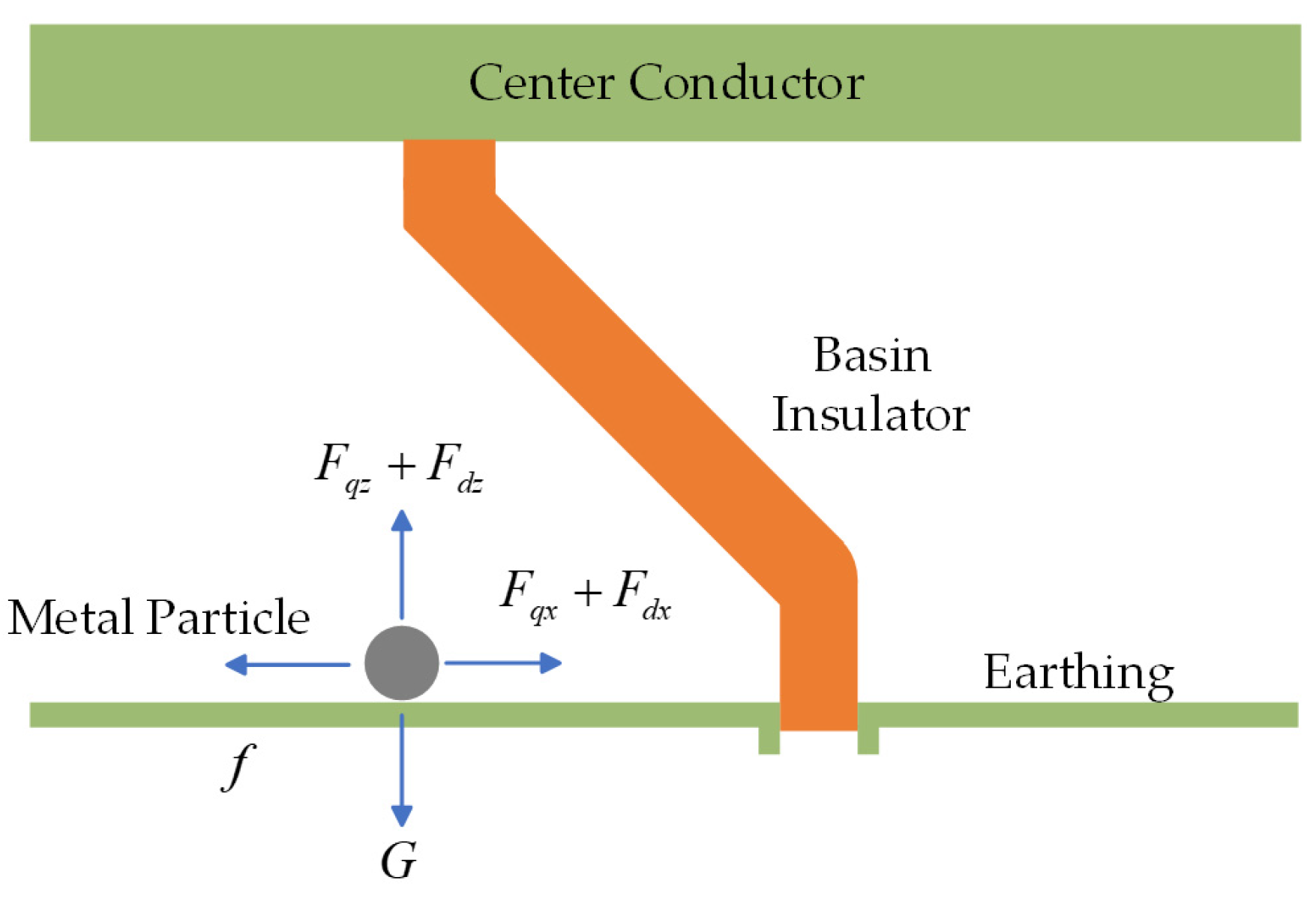
Figure 1. Force analysis of spherical metal particles.
Energies 17 05627 g001
Figure 2. Force analysis of metal particles after electrode coating.
Energies 17 05627 g002
Figure 3. Structure of ±550 kV GIS metal particle test platform.
Energies 17 05627 g003
Figure 4. Placement of film and particles.
Energies 17 05627 g004
Figure 5. The movement of metal particles observed from the observation port directly in front of the basin insulator. (a) Early stage of pressurization. (b) Sandstorm phenomenon of pressurization in the middle stage. (c) Late stage of pressurization.
Energies 17 05627 g005
Figure 6. The movement of metal particles observed from the observation port above the particle placement position. (a) Early stage of pressurization. (b) Early middle stage of pressurization. (c) Middle and late stage of pressurization. (d) Late stage of pressurization.
Energies 17 05627 g006
Figure 7. Distribution of metal particles after testing.
Energies 17 05627 g007
Figure 8. Jump motion of block metal particles. (a) Early stage of pressurization. (b) Middle stage of pressurization. (c) Late stage of pressurization.
Energies 17 05627 g008
Figure 9. Movement path of particles on the film.
Energies 17 05627 g009
Figure 10. Particle distribution. (a) The distribution ratio of metal foreign matter at different coating positions. (b) Distribution image of metal foreign matter at the coating position. (c) The axial curve of the number of metal foreign matter.
Energies 17 05627 g010
Figure 11. Wire particles movement on the film. (a) Early stage of pressurization. (b) Middle stage of pressurization. (c) Late stage of pressurization.
Energies 17 05627 g011
Figure 12. Particle movement characteristics at the coated boundary of the conductor. (a) Early stage of pressurization. (b) Middle stage of pressurization. (c) Late stage of pressurization.
Energies 17 05627 g012
Figure 13. Flashover caused by wire particles. (a) Photo of insulator flashover during pressurization. (b) Photo of insulator flashover during pressurization.
Energies 17 05627 g013
Figure 14. Movement of flaky particles after coating. (a) Before pressurization. (b) After pressurization.
Energies 17 05627 g014
Table 1. Forces on metal particles in electric field.
Force TypeForce DirectionForce Magnitude
Coulomb Forcez F q z = k q r E c z
−x F q x = k q r E c x
Gravity−z F d x = 4 π r 3 ρ g / 3
Electric Field Gradient Forcez F d x = 2 π r 3 ε 0 ε 1 E x 2
−x F d z = 2 π r 3 ε 0 ε 1 E z 2
Gas Resistance−v F f = μ N
−v F f = δ R N
Disclaimer/Publisher’s Note: The statements, opinions and data contained in all publications are solely those of the individual author(s) and contributor(s) and not of MDPI and/or the editor(s). MDPI and/or the editor(s) disclaim responsibility for any injury to people or property resulting from any ideas, methods, instructions or products referred to in the content.