Abstract
The solar heat gain is an important component of building cooling load, and its magnitude affects building energy consumption directly. In buildings with glass curtain walls, the window to wall rate is close to 1, so the amount of solar heat gain is huge, which directly determines the energy consumption level of a building’s air conditioning system. In fact, incident solar radiation can escape to the exterior through the transparent envelope, which cannot be ignored in buildings with glass curtain walls. This will cause changes in solar heat gain, so the solar heat gain coefficient (SHGC) needs to be corrected. In this paper, the heat transfer process of solar radiation in window shading systems is analyzed, and an amended calculation model for the SHGC is established. Multiple forms of windows and shading systems are selected and their SHGC-amended factor for rooms with different orientations under different standard calculation conditions in various countries is calculated. As the number of glass layers increases, the transmittance of the window gradually decreases, the reflectance and absorbance gradually increase, and the SHGC value decreases. The SHGC-amended factor decreases with an increasing escape rate, and the two can be approximated as a linear correlation. The weakening effect of shading on the solar heat gain of the buildings is overestimated. The SHGC-amended factor proposed in this paper can calculate building solar heat gain more accurately.
1. Introduction
According to the International Energy Agency, the building sector accounts for 34% of global final energy consumption and is responsible for 37% of total CO2 emissions [1]. The energy consumption of air conditioning systems accounts for a large proportion of building energy consumption. The level of air conditioning energy consumption is determined by the building load. In summer, the building has a cooling load and in winter a heating load. The building cooling load is the amount of heat that the air conditioning system needs to remove from the building in order to maintain a comfortable indoor temperature. Solar radiation transmitted to the interior through the transparent envelope becomes the indoor heat gain and ultimately part of the building cooling load. The building envelope, particularly windows, plays a crucial role in determining heat gain and loss within buildings [2,3]. The solar heat gain is large and fluctuates greatly, especially in buildings with a large window to wall rate [4,5]. For instance, the solar heat gain of buildings with glass curtain walls far exceeds that of traditional buildings.
The solar heat gain entering the room through a transparent envelope consists of two parts: one part is the solar radiation that is directly transmitted into the room, and the other part is the heat that is absorbed by windows and then transferred to the interior after the temperature rises. The heat flux into the indoor room contains the convective heat transfer and the longwave radiation heat transfer that happens because of the increased window temperature after absorbing partial incident solar radiation. In the calculation method of building load [6], this part of the heat is calculated through the solar radiation heat gain coefficient (SHGC), which incorporates all the effects of the incident solar radiation. The SHGC can be obtained through experimental and numerical methods. The experimental method is the hot box method, and institutions or scholars in various countries have established laboratories for targeted research, such as the Lawrence Berkeley National Laboratory [7], Canada National Solar Test Facility [8], National Fenestraten Rating Council [9,10], and Fraunhofer Institute for Solar Energy Systems in Germany [11]. Some scholars from universities have also conducted research on the SHGC. A team of scholars from Queen’s University, Ryerson University, and the University of Waterloo in Canada studied the effects of different shading components on longwave radiation heat transfer and convective heat transfer during thermal processes [12,13]. Jiang conducted research of the louver blind shading’s influence on the longwave radiative heat exchange and forced convective heat transfer [14,15,16].
The SHGC can also be numerically calculated by establishing an energy balance model for the overall window shading system [17]. In the thermal balance model, the sunshade components are equivalently treated as a layer of components, which together with the transparent enclosure structure form an n-layer transparent transmission system model. The thermal balance equations of each layer of components and the surrounding environment are solved by combining them. This calculation method is used in simulation software such as EnergyPlus (version 23.2.0) [18] and Window [19]. SHGC-specific calculation boundary conditions are also specified in the standards for windows both domestically and internationally.
As an important thermal parameter of the transparent envelope, the SHGC has detailed value regulations in the standards, such as ISO 19467 [20], GB50189 of China [21], ASHRAE Standard 90.1 of the US [22], and Building Regulations of the UK [23]. The specific values and regulations of each country or region may vary, and suitable standards are usually developed based on local climate conditions. For instance, there are five climate zones in China, and the thermal performances of building envelopes are detailed and regulated for each climate zone. For example, in hot summer and cold winter climate zones, there is a need for heat isolation in summer, so buildings with larger window to wall rates have a lower SHGC for glass or curtain walls to prevent excessive solar heat gain and energy consumption. Specific boundary conditions for the numerical calculation of the SHGC have been specified in the window standards of different countries, as shown in Table 1. There is a significant difference in the parameter settings in the different standards, which means that the SHGC values calculated for the same window under different standard conditions are not the same.

Table 1.
Calculation conditions for SHGC in different standards.
The SHGC is defined as a thermal performance parameter of a window, independent of the building. Among all standards, the SHGC can be measured under laboratory conditions and is not related to the actual building where the windows are used. In fact, the solar radiation transmitted into the indoor area may be reflected by the indoor walls and then escape to the outside through the transparent envelope. Usually, the escape situation is ignored when the window to wall rate is small, but in glass curtain wall buildings with a window to wall rate of almost 1, the escape of incident solar radiation cannot be ignored.
Due to the phenomenon of solar radiation escape in buildings with glass curtain walls, not all incident solar radiation will ultimately be converted into indoor heat gain. At the same time, due to the existence of escape solar radiation, both indoor and outdoor sides of the window have sources of solar radiation, so the amount of radiation absorbed by the window and the amount of heat transferred indoors also change. Therefore, for buildings with glass curtain walls, the building’s solar heat gain will change due to the existence of escape solar radiation, and the SHGC values need an amended calculation.
In this paper, the heat transfer process of solar radiation in window shading systems is analyzed, and an amended calculation model for the SHGC is established. Multiple forms of windows and shading systems are selected and their SHGC-amended factor for rooms with different orientations under different standard calculation conditions in various countries are calculated.
2. Amended Calculation Models
2.1. Solar Radiation Transfer Model in Multilayer Transmission System
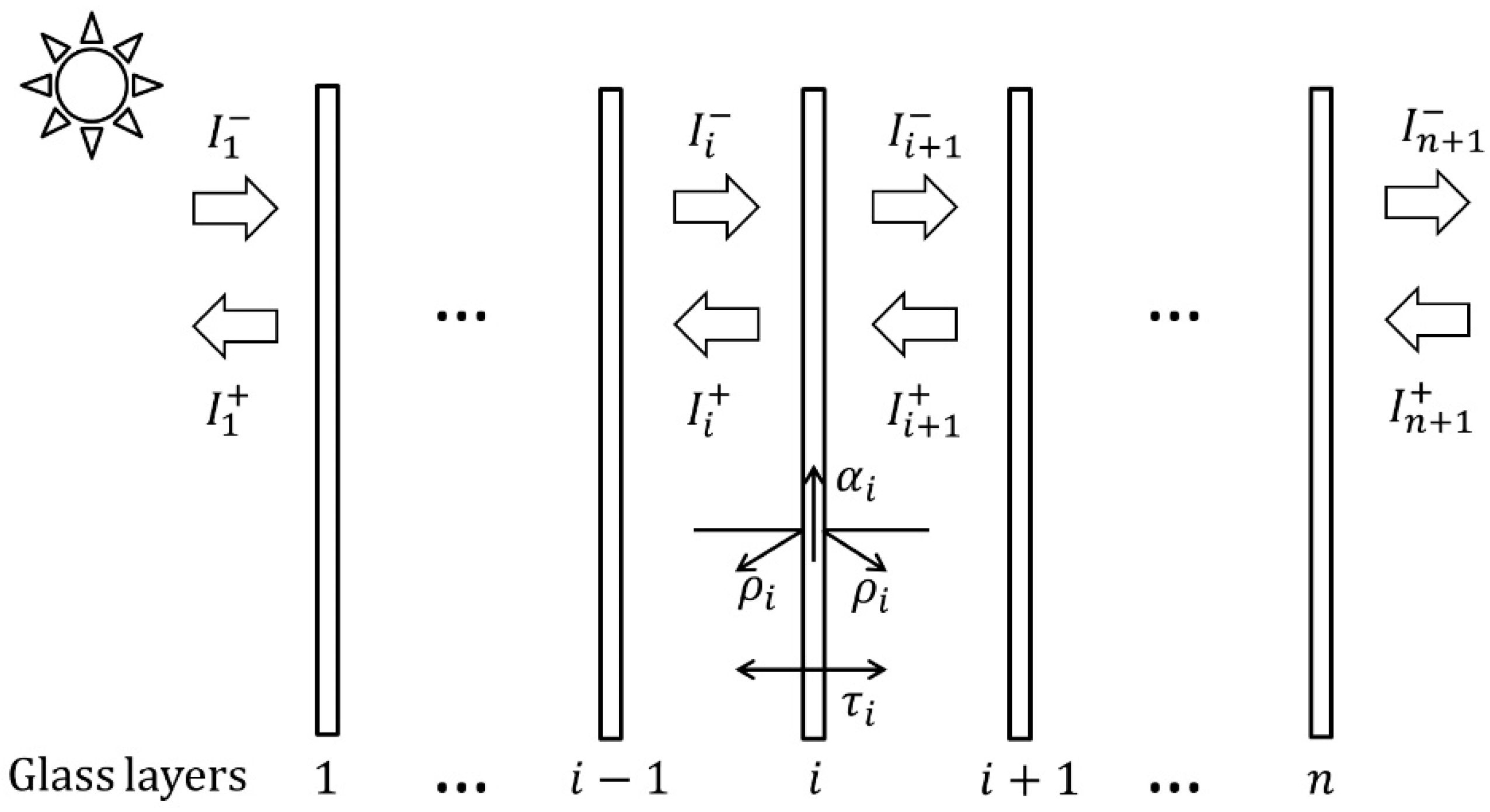
A window is a transparent enclosure that is always paired with a shade on the inside or outside. Sun shading facilities come in different forms and configurations such as roller blinds, louvers, etc. Windows are composed of single or multiple layers of glass, and the window shading system is referred to as a multilayer transmission system. Single-layer glass exhibits three phenomena of transmission, reflection, and absorption of solar radiation, while between multiple layers of glass, solar radiation undergoes repeated transmission, reflection, and absorption. Figure 1 shows the transmission of solar radiation in a multilayer transparent transmission system.
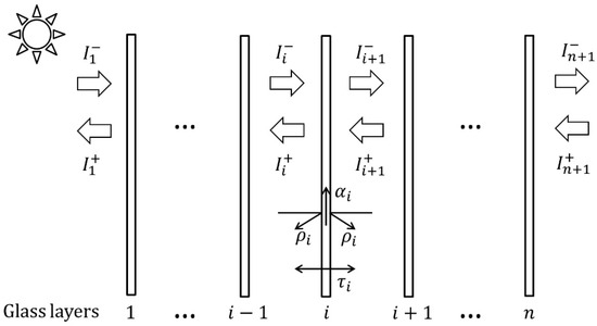
Figure 1.
Schematic diagram of solar radiation transfer in multilayer transmission system.
In a multilayer transmission system, the first layer is the outermost layer and the nth layer is the innermost layer. is the reflectivity, is the transmissivity, and is the absorptivity. For glass and shading components, it is considered that the outer surface characteristics are consistent with the inner surface. For the ith layer, there is a transfer of solar radiation between the adjacent and layers. For example, the solar radiation transferred from the th layer to the th layer is , and the solar radiation transferred from the th layer to the th layer is . The superscript “+” indicates the transfer towards the outdoor direction, and “−” indicates the transfer towards the indoor direction. For the outermost layer, is the solar radiation intensity that reaches the outer side of the room, while for the innermost layer, is the actual solar radiation intensity that enters the room.
Through analysis, it can be concluded that and are as follows:
The solar radiation from the atmosphere undergoes infinite reflections in an n-layer transmission system. As shown in Equation (2), for the th layer, in addition to the reflection part of , also includes the transmission part of , which is from the th layer. Therefore, is influenced by , which is from the th layer, and of the th layer is influenced by the th to th layers.
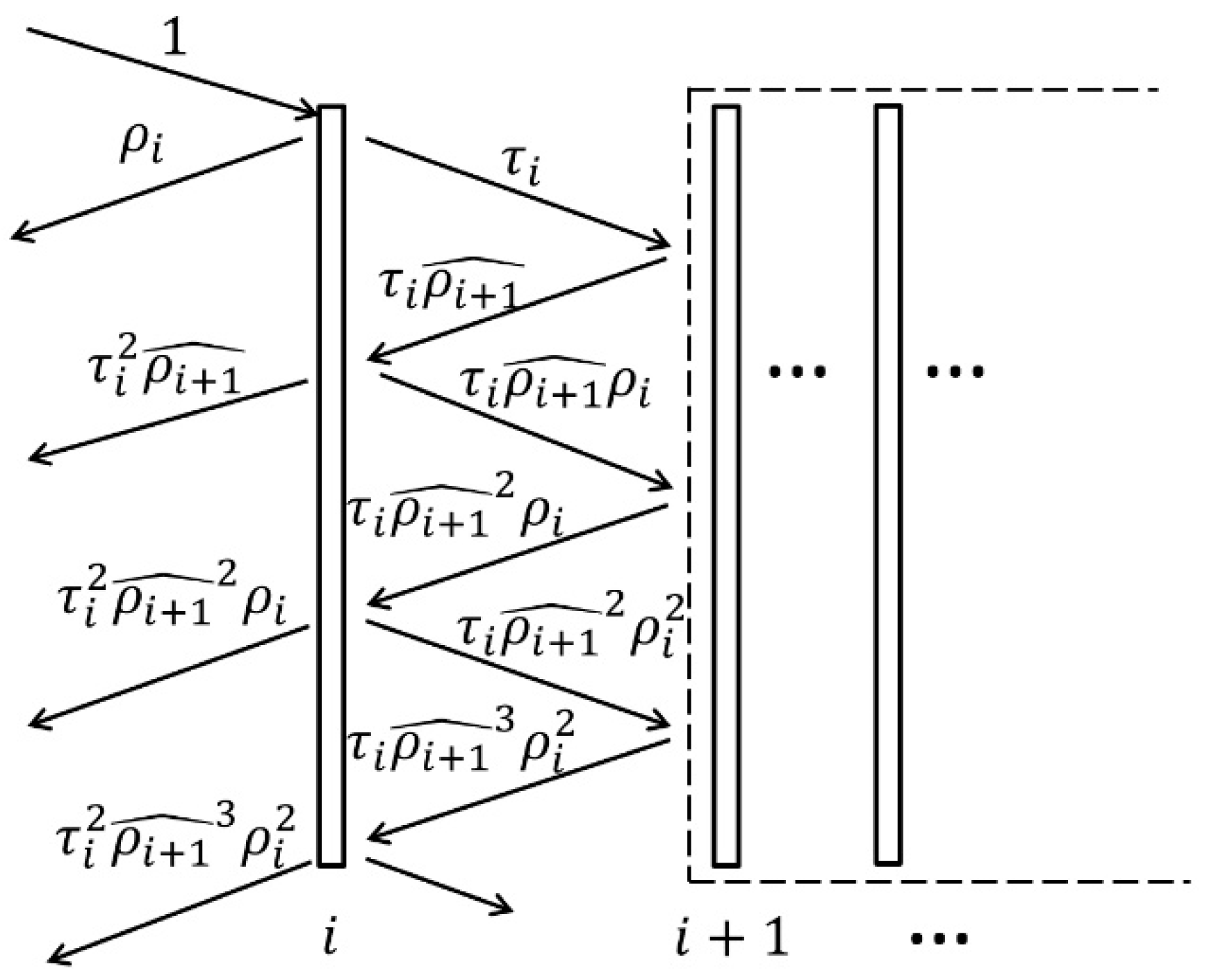
Figure 2 is a schematic diagram of solar radiation transfer through the th layer of an n-layer transmission system. To solve the and of each layer, assuming that the th to th layers are taken as a whole, the external surface reflectivity of the whole is .
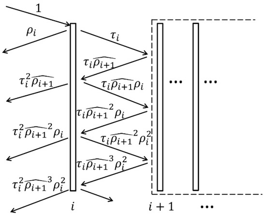
Figure 2.
Schematic diagram of solar radiation transfer through the th layer.
Therefore, the reflectivity of the whole is as follows:
The transmissivity of the whole is
The amount of solar radiation transfer and of the ith layer can be derived from Equations (5) and (6):
The solar radiation that transmits through the multilayer transmission system is as follows:
As shown in Figure 1, for the whole multilayer transmission system, its transmissivity , reflectivity , and absorptivity are as follows:
2.2. Amended Energy Balance Model
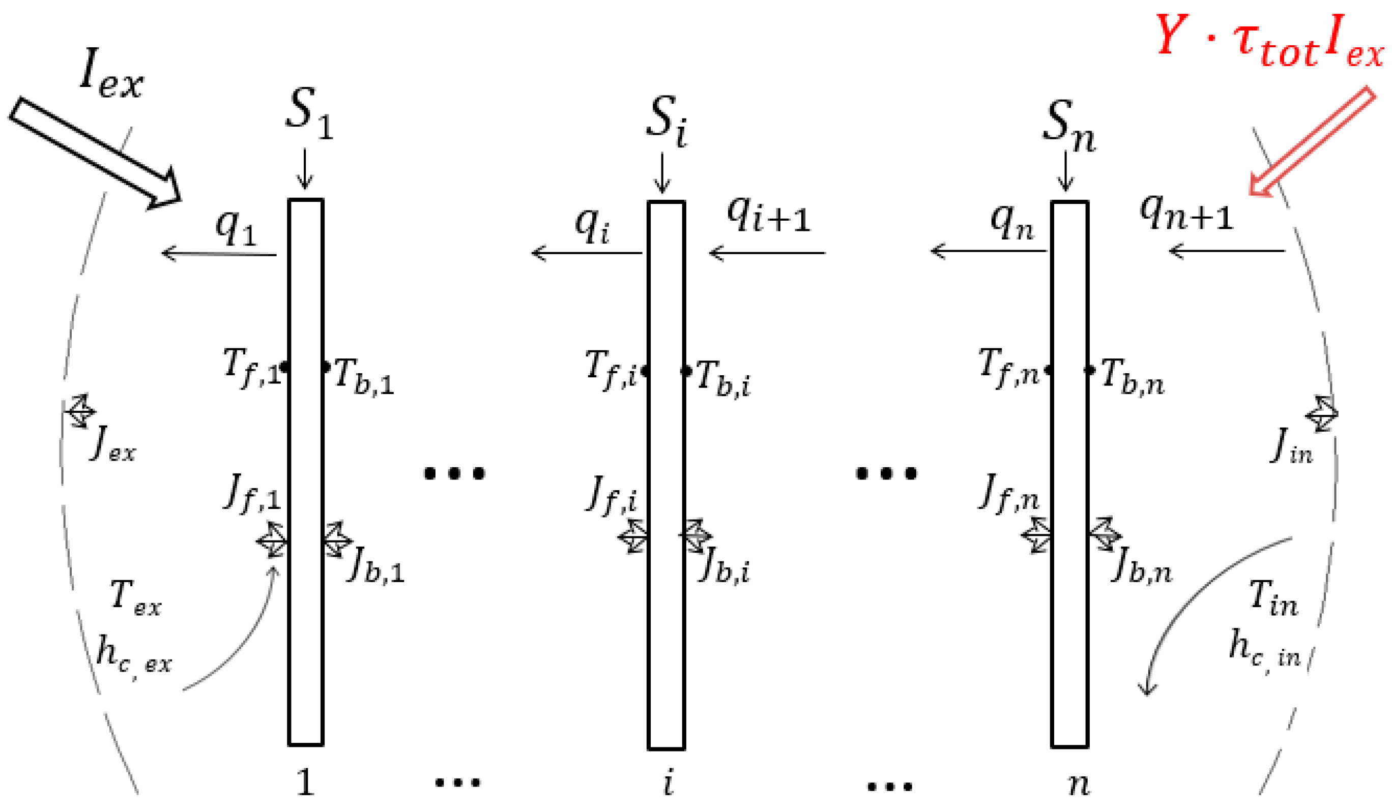
In the heat transfer process of a multilayer transmission system, there are simultaneous phenomena of conduction, convective, and radiative heat transfer. Figure 3 shows the boundary conditions and energy balance for each layer. It is different from the energy balance of the system in the ISO-15099 standard. Considering the existence of escape radiation, there are solar radiation sources on both indoor and outdoor sides of the multilayer transmission system. The solar radiation escape rate is represented by . In addition to the external solar radiation source , there are also escaping solar radiation sources on the indoor side. The amended calculation of the SHGC can be performed through system energy balance analysis:
where is the heat fluxes into the indoor environment through the transmission system with specific incident solar radiation, and is the heat fluxes into the indoor environment without incident solar radiation.
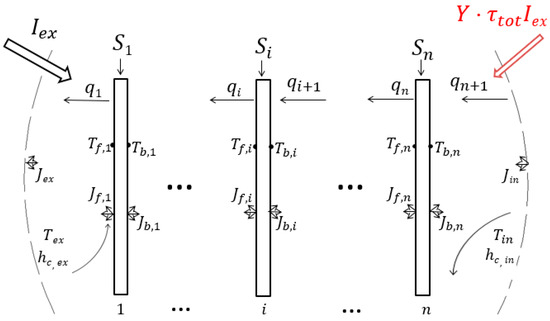
Figure 3.
Schematic diagram of energy balance in multilayer transmission system.
As mentioned earlier, the amended SHGC consists of two parts. In Equation (13), the first term is the proportion of solar radiation directly transmitted into the room. The second term is the proportion of solar radiation heat that is absorbed by windows and then transferred to the interior after the temperature rises. represents the amount of heat transfer due to the temperature difference between indoor and outdoor air.
For the th layer, is the heat flux across the gap between layers, is the solar radiation absorbed by the th layer, is the outer surface temperature, is the inner surface temperature, is the radiosity from the outer surface, and is the radiosity from the inner surface. and are radiosity from the outdoor and indoor environments and are boundary conditions for the calculation. and are the outdoor and indoor air temperature. and are the convective heat transfer coefficients on the outside and inside.
These unknowns need to be calculated by solving the equations. Except for the solar radiation escape rate , the boundary conditions are known, and their values are specified by standards.
The calculation of the solar radiation escape rate is implemented using the asymmetrical distribution model of solar radiation, which was established in the previous research [25,26]. This model is based on the RIM method used to discretize indoor surfaces, analyze the radiosity for each surface, and obtain the accurate distribution of incident solar radiation on the indoor surfaces through calculation. The total amount of radiation reaching the window surface can be counted to calculate the escape solar radiation .
As shown in Figure 3, the heat flux transferred between each layer can be obtained through system energy balance analysis:
For the th layer, the energy balance system of the equations is as follows:
where is the emissivity of the th layer, is the black emissive power, which is , is , is the thickness of the th layer, and is the thermal conductivity of the th layer.
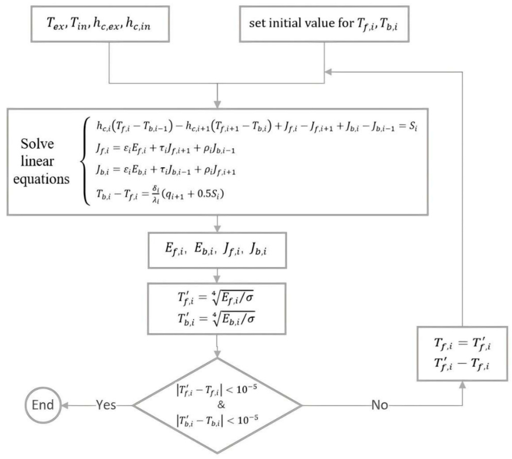
There are 4n unknowns in the 4n system of equations, namely , , , , and the equations can be solved by an iterative method, with the steps shown in Figure 4. Firstly, the initial values of the layers’ temperatures ( and ) are set, and and can be calculated. Secondly, , , , can be obtained by solving the 4n system of equations, and the new set of layers’ temperatures ( and ) can be calculated. Finally, by comparing the new set of temperatures with the original temperatures, if the difference is less than 10−5, the iterative calculation can be stopped. Otherwise, the old set of temperatures is replaced with the new set and the calculation is started from the first step. at different escape rates can be obtained, and the SHGC and the amended factors can be calculated according to Equation (13).
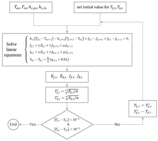
Figure 4.
Schematic diagram of the computational steps involved in solving the linear equations.
3. Results and Discussion
3.1. The Optical Performance of the Transmission Systems
To calculate the heat transfer through the n-layer system, it is necessary to clarify the optical performance of each layer. The thickness of the white glass is 6 mm. To discuss the effects of different forms of external shading and internal shading, the same type of shading was selected for research. The chosen shading device is a light gray roller shade. For glass and shading components, it is believed that the outer surface’s characteristics are consistent with those of the inner surface, and the specific optical performance is shown in Table 2.

Table 2.
The optical performance of single layer.
Different transmission systems are chosen for the simulation calculation. There are three types of window forms: single-glazing, double-glazing, and triple-glazing glass. Considering that double-glazing is commonly used in practical engineering, it is considered a typical window and is calculated with two types of shading: external shading and internal shading.
Since the th layer is the last layer of the transmission system, is 0. The optical performance of different transmission systems can be calculated according to Equations (10)–(12), and the results are shown in Table 3.

Table 3.
The optical performance of multilayer transmission systems.
According to the data in Table 3, as the number of glass layers increases, the system transmissivity gradually decreases, while the reflectivity and absorptivity gradually increase. However, when shading is set up, the system transmissivity significantly decreases. The installation position of shading components has no effect on the transmissivity of multilayer transmission systems, but the overall reflectivity and absorptivity of the system are greatly affected by the shading installation position.
3.2. Original SGHC in Different Standards
As shown in Table 1, there are different values for the set values of the calculation conditions in different standards, so single-, double-, and triple-glazing were selected for the calculation, and a comparison of the SHGC calculation results under different standards is shown in Figure 5.

Figure 5.
SHGC values for multilayer glazing under different standards: (a) summer; (b) winter [10,17,24].
The NFRC200 standard only includes summer conditions, so Figure 5a shows a comparison of the three standards, while Figure 5b shows a comparison of the results of the two standards ISO15099 and JGJ151. The greater the number of glass layers of the window, the smaller the SHGC value, which is also similar to the change rule of transmittance in Table 3. As seen in Figure 5a, the order of the size of SHGC values of the same window in summer is NFRC200 > ISO15099 > JGJ151. Although the set value in the NFRC200 standard differs greatly from the remaining two standards, its calculated value is very close to the SHGC calculated value of ISO15099. And as can be seen in Figure 5b, ISO15099 is very close to the JGJ151 value. Comparing Figure 5a with Figure 5b, it can be seen that the SHGC value of the same window in ISO15099 standard is higher in summer than in winter, whereas in JGJ151 standard, the SHGC values remain the same in summer and winter.
3.3. Amended Calculation of SHGC
The solar radiation escape rate is influenced by many parameters, such as building location, orientation, room size, window-to-wall ratio, reflectance absorptivity of indoor surfaces, and the thermal parameters of the windows. Even if all the above parameters are determined, the value of escape rate is not a fixed value but dynamic. This is because the escape rate varies with the azimuth and altitude angles of solar radiation and the ratio of direct to diffuse solar radiation at different moments. According to a previous study [25], escape rate varies in the range of 5–16% under different room sizes and indoor wall reflectance conditions. However, this study only explored escape rate at a single moment and did not consider the effects of solar altitude angle and azimuth angle.
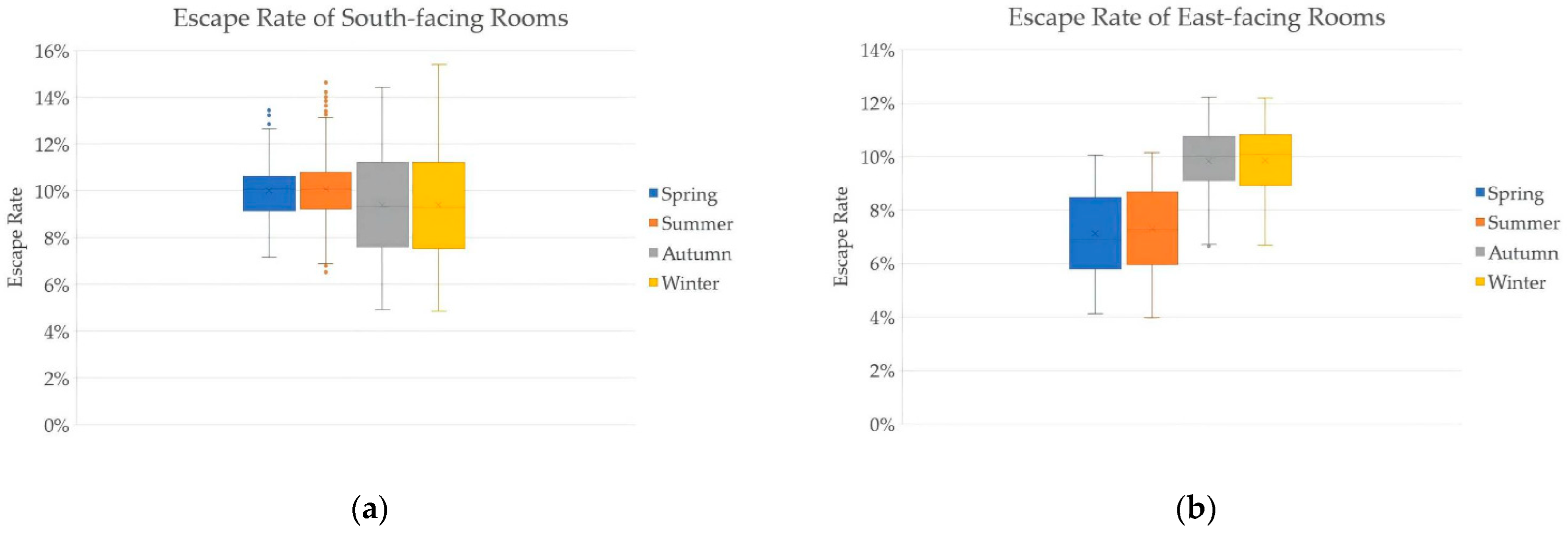
On the basis of a sun-patch tracking model with actual weather files, year-round escape rates were calculated. The simulated building is located in Shanghai, which is in a hot summer and cold winter climate region, with both summer cooling and winter heating requirements. The size of the simulated room is L = 3 m, W = 4.5 m, H = 3 m. The absorptance of the floor is set to 0.8, and the absorptance of the other indoor walls is set to 0.4. The windows are double-glazed. The escape rate of buildings with different orientations is calculated, and the calculation result of 8760 h through the year is shown in Figure 6. Because the north direction is rarely irradiated by solar radiation directly and generally does not adopt the form of a glass curtain wall, the north-facing room is not discussed. However, the east orientation and the west orientation are symmetrical to each other, so Figure 6 shows the results of escape rates in different seasons for the south- and east-orientated rooms. The statistical results of the escape rate in summer and winter are shown in Table 4. The variation range of escape rate is 3.98% to 15.42%. However, if the conditions, such as building location and room dimensions, are changed, the results of escape rate will be changed. Therefore, in the SHGC-amended calculation, the variation range of the escape rate value is set to 0–20%.
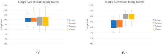
Figure 6.
Escape rate in different seasons for different orientations: (a) south; (b) east.

Table 4.
Escape rate of rooms facing south and east in summer and winter.
3.3.1. Subsubsection
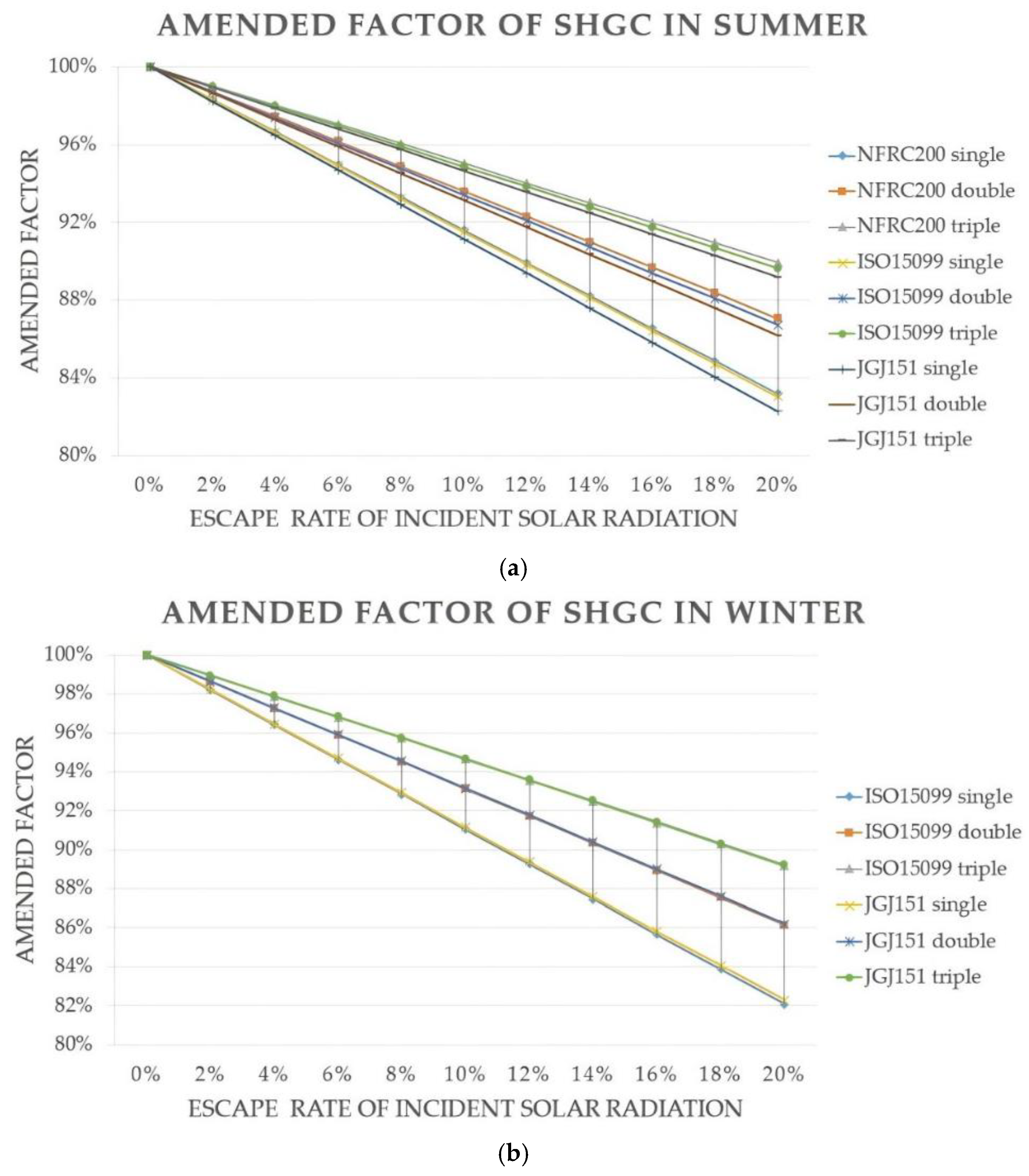
Using the escape rate values as boundary conditions, numerical calculations were performed using the energy balance system equations to calculate the SHGC-amended factors under different standards. The boundary conditions, such as intensity of solar radiation, outdoor air temperature, indoor air temperature, and convective heat transfer coefficients on both sides of the system, are set in Table 1. The calculation results for multilayer glazing are shown in Figure 7.
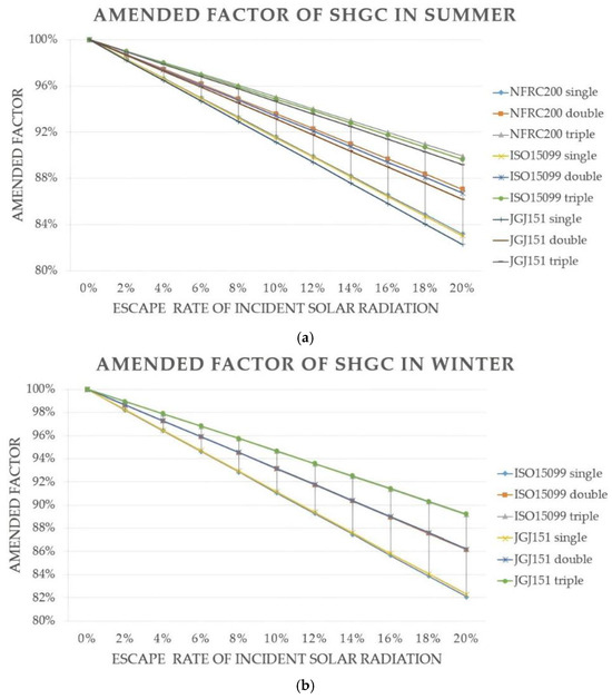
Figure 7.
The influence of escape rate on SHGC-amended factor in different standards: (a) summer; (b) winter [10,17,24].
It is obvious that the SHGC-amended factor decreases with an increasing escape rate. However, the relationship can be approximated as a linear correlation according to Figure 7. The influence of the number of system layers n on the SHGC-amended factor is significant. The rate of change in the SHGC-amended factor with the escape rate is different for different windows, with the largest change for single-glazing. This is because as the number of layers increases, the transmissivity of the multilayer transmission system decreases, the absorptivity increases, and the amount of escape solar radiation decreases. After the glass absorbs radiation and heats up, it conducts more heat into the room, resulting in an increase in the SHGC-amended factor. For the same value of the escape rate, the SHGC-amended factors in different standards are similar, especially in Figure 7b, where the change curves of the two standards almost overlap.
3.3.2. Escape Rate Reference Value and Corresponding SHGC-Amended Factor
Based on the results of the year-around simulation of the escape rate of the actual building, the variation in the escape rate of solar radiation can be obtained, and the average of the escape rate in summer and winter can be used as the reference value of the escape rate of the building and used in the SHGC-amended calculation. For example, according to Table 4, the escape rate reference value of the simulated building in Shanghai is 10.09% for the south-facing room in summer and 7.3% for the east-facing room. SHGC-amended factors for different standards can be obtained by looking up the data in Figure 7 or by solving energy balance equations. For example, Table 4 shows solar radiation escape rates in summer versus winter, and SHGC-amended calculations can be calculated based on the average values. Detailed results are shown in Table A1.
The original SHGC is independent of the orientation of the building, and the different escape rate values of rooms with different orientations result in differences in the amended SHGC. For example, under three standards’ calculation conditions, the SHGC-amended factor for south-facing rooms is smaller than that for east-facing rooms in summer and is opposite in winter. This is consistent with the escape rate magnitude in Table 4. The differential performance of solar radiation escape rates between south-facing and east-facing rooms in different seasons is due to the solar altitude angle and azimuth angle. In summer, the point of direct sunlight is close to the Tropic of Cancer, and for the moments when each room has the same incidence azimuth (e.g., 9 o’clock in the east-facing room and 12 o’clock in the south-facing room), the solar altitude angle of the south-facing room is larger than that of the east-facing room, and therefore the beam spot formed in the room is close to the glass curtain wall, and the angular coefficient between the beam spot and the transparent enclosure is larger, meaning that the escape rate is larger than the correction coefficient of the SHGC. The south direction solar altitude angle is greater than the east and west direction, so the direct spot formed in the room is close to the glass curtain wall, and the angular coefficient between the irradiated spot formed and the transparent enclosure is larger, and thus the escape rate and the amended factor of the SHGC are larger. In winter, the sun’s point of direct sunlight is close to the Tropic of Capricorn, the length of day is short, the length of time that the east-facing room is exposed to solar radiation is shorter than that of the south-facing room, and the situation that the sun’s altitude angle is small and the incidence azimuth is large does not occur (in the early morning of the east-facing room), so the situation that the escape rate of solar radiation is small is greatly reduced; therefore, the SHGC-amended factors for east-facing rooms are slightly bigger than those for south-facing rooms in winter.
An amended calculation for the SHGC of windows with shading is conducted. Two types of shading, external shading and internal shading, are calculated. The results are shown in Table A2. For windows with shadings, the SHGC-amended factors are all between 0.99 and 1. This is because shading not only blocks incident solar radiation but also blocks escape solar radiation. This leads to the fact that the solar radiation escape phenomenon is almost non-existent in the case of shading, so the difference between the SHGC before and after correction is not significant. Therefore, for windows without shadings, the SHGC value decreases after correction, while it remains almost unchanged under shading conditions. It can be seen that the existing calculation methods overestimate the weakening effect of shading on the solar heat gain of the buildings. The SHGC-amended factor proposed in this paper can calculate building solar heat gain more accurately.
4. Conclusions
The actual solar heat gain of a building is lower than the existing calculated values due to solar radiation escaping from glass curtain wall buildings. In this paper, a modified solar heat gain coefficient calculation model is proposed to investigate the modification coefficients of solar heat gain coefficients for different escape rates, and suggested values of modification coefficients for summer and winter are provided for rooms facing different directions according to different reference standards.
As the number of glass layers increases, the transmittance of the window gradually decreases, the reflectance and absorbance gradually increase, and the SHGC value decreases. The order of the size of original SHGC values of the same window in summer is NFRC 200 > ISO 15099 > JGJ 151.
The SHGC-amended factor decreases with an increasing escape rate, and the two can be approximated as a linear correlation. The influence of the number of system layers n on the SHGC-amended factor is significant. The rate of change in the SHGC-amended factor with the escape rate is different for different windows, with the largest change for single-glazing.
For windows with shadings, the SHGC-amended factors are all between 0.99 and 1. The existing calculation methods overestimate the weakening effect of shading on the solar heat gain of the buildings. The SHGC-amended factor proposed in this paper can calculate building solar heat gain and cooling load more accurately.
SHGC-amended factors for different standards can be obtained by looking up the data in Figure 7 or by solving a system of energy balance equations. Subsequently, we will continue to expand the number of cities for which calculations are conducted and form and improve the database of reference values for the SHGC-amended factor.
Author Contributions
Conceptualization, S.L. and D.Y.; methodology, S.L.; software (MATLAB version R2024a), S.L. and T.C.; validation, D.Y., X.H. and T.C.; investigation, X.H. and Z.W.; writing—original draft preparation, S.L. and X.H.; writing—review and editing, S.L. and D.Y.; visualization, D.Y. and Z.W.; project administration, Z.W.; funding acquisition, S.L. All authors have read and agreed to the published version of the manuscript.
Funding
This work was supported by the Scientific Research Foundation of Nanjing Institute of Technology (Grants No. YKJ201963).
Data Availability Statement
The original contributions presented in the study are included in the article, further inquiries can be directed to the corresponding author.
Conflicts of Interest
The authors declare no conflicts of interest.
Appendix A

Table A1.
Amended calculation for SHGC of windows under different standards.
Table A1.
Amended calculation for SHGC of windows under different standards.
| Season | Standard | Windows | Room Orientation | Original SHGC | Amended SHGC | Amended Factor |
|---|---|---|---|---|---|---|
| Summer | NFRC 200 | Single-glazing | South | 0.834 | 0.763 | 91.52% |
| East | 0.783 | 93.86% | ||||
| Double-glazing | South | 0.717 | 0.671 | 93.52% | ||
| East | 0.684 | 95.33% | ||||
| Triple-glazing | South | 0.625 | 0.593 | 94.98% | ||
| East | 0.602 | 96.38% | ||||
| ISO 15099 | Single-glazing | South | 0.830 | 0.759 | 91.43% | |
| East | 0.779 | 93.80% | ||||
| Double-glazing | South | 0.712 | 0.665 | 93.35% | ||
| East | 0.678 | 95.20% | ||||
| Triple-glazing | South | 0.621 | 0.589 | 94.82% | ||
| East | 0.597 | 96.27% | ||||
| JGJ/T 151 | Single-glazing | South | 0.815 | 0.742 | 91.06% | |
| East | 0.762 | 93.53% | ||||
| Double-glazing | South | 0.697 | 0.649 | 93.08% | ||
| East | 0.663 | 95.00% | ||||
| Triple-glazing | South | 0.606 | 0.574 | 94.60% | ||
| East | 0.583 | 96.11% | ||||
| Winter | ISO 15099 | Single-glazing | South | 0.811 | 0.743 | 91.58% |
| East | 0.739 | 91.18% | ||||
| Double-glazing | South | 0.695 | 0.650 | 93.54% | ||
| East | 0.648 | 93.22% | ||||
| Triple-glazing | South | 0.604 | 0.574 | 94.97% | ||
| East | 0.572 | 94.73% | ||||
| JGJ/T 151 | Single-glazing | South | 0.815 | 0.747 | 91.67% | |
| East | 0.744 | 91.27% | ||||
| Double-glazing | South | 0.697 | 0.652 | 93.57% | ||
| East | 0.650 | 93.26% | ||||
| Triple-glazing | South | 0.606 | 0.587 | 96.93% | ||
| East | 0.585 | 96.61% |

Table A2.
Amended calculation for SHGC of transmission systems with shadings under different standards.
Table A2.
Amended calculation for SHGC of transmission systems with shadings under different standards.
| Season | Standard | TransmissionSystems | Room Orientation | Original SHGC | Amended SHGC | Amended Factor |
|---|---|---|---|---|---|---|
| Summer | NFRC 200 | Double-glazing with external shading | South | 0.201 | 0.200 | 99.63% |
| East | 0.201 | 99.79% | ||||
| Double-glazing with internal shading | South | 0.281 | 0.279 | 99.39% | ||
| East | 0.280 | 99.58% | ||||
| ISO 15099 | Double-glazing with external shading | South | 0.231 | 0.230 | 99.47% | |
| East | 0.230 | 99.57% | ||||
| Double-glazing with internal shading | South | 0.356 | 0.355 | 99.65% | ||
| East | 0.355 | 99.77% | ||||
| JGJ/T 151 | Double-glazing with external shading | South | 0.221 | 0.220 | 99.41% | |
| East | 0.220 | 99.52% | ||||
| Double-glazing with internal shading | South | 0.338 | 0.336 | 99.45% | ||
| East | 0.337 | 99.58% | ||||
| Winter | ISO 15099 | Double-glazing with external shading | South | 0.210 | 0.209 | 99.52% |
| East | 0.209 | 99.45% | ||||
| Double-glazing with internal shading | South | 0.311 | 0.310 | 99.62% | ||
| East | 0.310 | 99.54% | ||||
| JGJ/T 151 | Double-glazing with external shading | South | 0.211 | 0.210 | 99.45% | |
| East | 0.210 | 99.39% | ||||
| Double-glazing with internal shading | South | 0.312 | 0.311 | 99.61% | ||
| East | 0.311 | 99.53% |
References
- United Nations Environment Programme. Global Alliance for Buildings and Construction. Global Status Report for Buildings and Construction: Beyond Foundations: Mainstreaming Sustainable Solutions to Cut Emissions from the Buildings Sector; United Nations Environment Programme: Nairobi, Kenya, 2024. [Google Scholar] [CrossRef]
- Wen, J.X.; Yang, S.J.; Xie, Y.X.; Yu, J.; Lin, B. A fast calculation tool for assessing the shading effect of surrounding buildings on window transmitted solar radiation energy. Sustain. Cities Soc. 2022, 81, 103834. [Google Scholar] [CrossRef]
- Li, Q.S.; Zhang, L.; Wang, X.C.; Su, X. Daylighting and energy performance of window with transparent insulation slats combined with building shading in the hot-summer and cold-winter zone. Sustain. Cities Soc. 2024, 114, 105772. [Google Scholar] [CrossRef]
- Lin, Z.; Song, Y.; Chu, Y.H. Summer performance of a naturally ventilated double-skin facade with adjustable glazed louvers for building energy retrofitting. Energy Build. 2022, 267, 112163. [Google Scholar] [CrossRef]
- Tao, Y.; Fang, X.; Setunge, S.; Tu, J.; Liu, J.; Shi, L. Naturally ventilated double-skin facade with adjustable louvers. Sol. Energy. 2021, 225, 33–43. [Google Scholar] [CrossRef]
- Ashrae Handbook Fundamentals; American Society of Heating, Refrigerating and Air-Conditioning Engineers: Atlanta, GA, USA, 2021.
- Klems, J.H.; Warner, J.L.; Kelly, G.O. A new method for predicting the solar heat gain of complex fenestration systems. ASHRAE Trans. 1995, 100, 1065–1086. [Google Scholar] [CrossRef]
- Elmahdy, A.H. Heating Transmission and R-value of Fenestration Using IRC Hot Box: Procedure and uncertainty analysis. ASHRAE Trans. 1992, 1, 838–845. [Google Scholar]
- NFRC 201; Procedure of Interim Standard Test Method for Measuring the Solar Heat Gain Coefficient of Fenestration Systems Using Calorimetry Hot Box Methods. National Fenestration Rating Council: Greenbelt, MD, USA, 2022. [CrossRef]
- NFRC 200; Procedure for Determining Fenestration Attachment Product Solar Heat Gain Coefficient and Visible Transmittance at Normal Incidence. National Fenestration Rating Council: Greenbelt, MD, USA, 2014.
- Kuhn, T.E. Calorimetric determination of the solar heat gain coefficient g with steady-state laboratory measurements. Energy Build. 2014, 84, 388–402. [Google Scholar] [CrossRef]
- Oosthuizen, P.H.; Sun, L.; Harrison, S.J.; Naylor, D.; Collins, M. The Effect of Coverings on Heat Transfer from a Window to a Room. Heat Transf. Eng. 2005, 26, 47–65. [Google Scholar] [CrossRef]
- Oosthuizen, P.H. Three-Dimensional Effects on convective heat transfer from a window/plane blind system. Heat Transf. Eng. 2008, 29, 565–571. [Google Scholar] [CrossRef]
- Jiang, F.J.; Li, Z.R.; Zhao, Q.; Tao, Q.; Lu, S. Accuracy analysis and improvement of the Blind Enclosure Model to calculate the longwave radiative heat transfer for a façade with louver blinds. Energy Build. 2017, 140, 98–109. [Google Scholar] [CrossRef]
- Jiang, F.J.; Li, Z.R.; Zhao, Q.; Yuan, Y.; Lu, S. Flow field around a surface-mounted cubic building with louver blinds. Build. Simul. 2019, 12, 141–151. [Google Scholar] [CrossRef]
- Jiang, F.J.; Tao, S.W.; Tao, Q.H.; Yuan, Y.; Zheng, J. The effect of louver blinds on the wind-driven cross ventilation of multi-storey buildings. J. Build. Eng. 2022, 54, 104614. [Google Scholar] [CrossRef]
- ISO 15099-2024; Thermal Performance of Windows, Doors and Shading Devices-Detailed Calculations. ISO: Geneva, Switzerland, 2024. [CrossRef]
- EnergyPlus, version 23.2.0. Engineering Reference–Version 23.2.0 Documentation. Ernest Orlando Lawrence Berkeley National Laboratory: Berkeley, CA, USA, 2023.
- Lawrence Berkeley National Laboratory, Windows and Envelope Material Group. Window Technical Documentation; Lawrence Berkeley National Laboratory, Windows and Envelope Material Group: Berkeley, CA, USA, 2018.
- ISO 19467-2017; Thermal Performance of Windows and Doors—Determination of Solar Heat Gain Coefficient Using Solar Simulator. ISO: Geneva, Switzerland, 2017. [CrossRef]
- GB 50189; Design Standard for Energy Efficiency of Public Buildings. Ministry of Housing and Urban-Rural Development of the People’s Republic of China: Beijing, China, 2015. (In Chinese)
- ASHRAE Standard 90.1-2019; Energy Efficiency Standards for Buildings Except Low-Rise Residential Buildings. ASHRAE: Peachtree Corners, GA, USA, 2019; ISSN 1041-2336.
- Billington, M.J.; Barnshaw, S.P.; Bright, K.T.; Crooks, A. Building Regulations Part L: Conservation of Fuel and Power; 2021; ISBN 978-1-914124-79-2. Available online: https://assets.publishing.service.gov.uk/media/63d8edbde90e0773d8af2c98/Approved_Document_L__Conservation_of_fuel_and_power__Volume_2_Buildings_other_than_dwellings__2021_edition_incorporating_2023_amendments.pdf (accessed on 29 October 2024). [CrossRef]
- JGJ/T 151; Calculation Specification for Thermal Performance of Windows, Doors and Glass Curtain Walls. Ministry of Housing and Urban-Rural Development of the People’s Republic of China: Beijing, China, 2016. (In Chinese)
- Lu, S.Y.; Li, Z.R.; Zhao, Q.; Jiang, F. Modified calculation of solar heat gain coefficient in glazing façade buildings. Energy Procedia 2017, 122, 151–156. [Google Scholar] [CrossRef]
- Lu, S.Y.; Huang, X.Q.; Chen, T.; Wang, Z. A comparative study on the distribution models of incident solar energy in buildings with glazing facades. Buildings 2023, 13, 2659. [Google Scholar] [CrossRef]
Disclaimer/Publisher’s Note: The statements, opinions and data contained in all publications are solely those of the individual author(s) and contributor(s) and not of MDPI and/or the editor(s). MDPI and/or the editor(s) disclaim responsibility for any injury to people or property resulting from any ideas, methods, instructions or products referred to in the content. |
© 2024 by the authors. Licensee MDPI, Basel, Switzerland. This article is an open access article distributed under the terms and conditions of the Creative Commons Attribution (CC BY) license (https://creativecommons.org/licenses/by/4.0/).

