Article

Electrical Tortuosities of Porous Structures Based on Triply Periodic Minimal Surfaces and Honeycombs for Power-to-Heat Systems

Institute of Engineering Thermodynamics, German Aerospace Center, 70569 Stuttgart, Germany
*
Author to whom correspondence should be addressed.
Energies 2024, 17(22), 5781; https://doi.org/10.3390/en17225781
Submission received: 25 October 2024 / Revised: 8 November 2024 / Accepted: 14 November 2024 / Published: 19 November 2024
(This article belongs to the Section J: Thermal Management)

Abstract

:
Power-to-heat (P2H) systems offer an efficient solution for decarbonization by facilitating the integration of renewable energy into the industrial, heating, and transport sectors. Its key requirements include high thermal efficiency and an appropriate electrical resistivity to meet application-specific electrical needs. When designing P2H systems, materials and electrical boundary conditions are often limited by application-specific requirements, whereas geometric structures offer high degrees of freedom. While thermal design calculations are often straightforward due to a variety of available Nusselt and pressure loss correlations, simplified design pathways, particularly for porous structures, are lacking in electrical design. Given the wide range of geometric degrees of freedom for porous structures and the fact that detailed modeling involves substantial computational effort, this work employed electrical tortuosity to capture and correlate the geometry-dependent impacts on the effective electrical resistance in a compact way. Honeycomb and triply periodic minimal surface (TPMS)-based structures were selected for this purpose, as they are characterized by high specific surfaces, allowing for high total heat transfer coefficients. The results show that the effective electrical resistance of both TPMS and honeycomb structures can be adjusted by the geometric structure. It was found that the electrical tortuosities of the investigated TPMS structures are nearly identical, while honeycomb structures show slightly higher values. Furthermore, the electrical tortuosity is mainly a function of the void fraction and does not change with the specific surface when the void fraction is kept constant. Finally, correlations for electrical tortuosity depending on geometric parameters with a mean error below 5% are derived for the first time, thereby providing a basis for simplified and computationally efficient electrical design calculations for P2H systems.

1. Introduction

Decarbonizing the economy is a key element in the fight against climate change and essential for achieving carbon neutrality. An efficient measure for decarbonization is represented by power-to-heat (P2H) systems, as they facilitate the integration of renewable energies in the industrial, heating, and transport sectors. For instance, the use of electric flow heaters with high volumetric heating capacities and operating temperatures can enable the replacement of natural gas burners in industrial applications [1]. Furthermore, the integration of a P2H module in large-scale electricity storage, e.g., adiabatic compressed air energy storage (A-CAES) or pumped thermal energy storage (PTES), allows for increased power plant flexibility and decreased component sizes due to the high temperatures generated, leading to improved cost efficiency [2,3,4]. Another field of application are directly heated solid media thermal energy storage systems in battery electric vehicles (BEVs). Such systems provide alternative thermal management concepts, preventing a loss of range during the cold season, as heating the interior requires alternative sources due to the absence of combustion heat [5]. As electrical current flows directly through the storage inventory, this enables higher and more uniform charging power compared to a storage system based on indirect resistance heating, such as metallic heating wires integrated into an electrically nonconductive honeycomb structure [6,7].
For all these applications, thermally efficient systems are needed that enable high heat transfer between the solid and fluid, while also exhibiting a suitable electrical resistance per volume to meet application-specific electrical requirements. Additionally, there may be other requirements, such as high-temperature capability, high power, or high storage densities. When designing P2H systems, the degrees of freedom are essentially limited to three key aspects: material selection, electrical boundary conditions, and the geometric structures used. The choice of electrically conductive materials is limited to those that are suitable for the operating temperature range, which narrows the available range of electrical resistivity. Regarding electrical boundary conditions, there are constraints related to the application itself or the electricity grid, such as maximum permissible current, available grid voltage, or power input. For stationary applications, there may be little scope for adjustment, whereas in the case of a directly heated thermal energy storage system in a BEV, these constraints are directly linked to the existing charging station infrastructure. In contrast, the selection and customization of (porous) geometric structures offers nearly unlimited design flexibility for P2H systems due to the various geometry options. The key characteristics of these structures include their surface area and void fraction.
While thermal design calculations are often straightforward due to a variety of available Nusselt and pressure loss correlations, simplified design pathways, particularly for porous structures, are lacking in electrical design calculations. Given the wide range of geometric degrees of freedom for porous structures, a detailed depiction leads to tremendous modeling and computational efforts. For this reason, the tortuosity, a widely used concept in the literature, is utilized [8] to capture geometric-dependent impacts on the effective electrical resistance in a compact way. Tortuosity is a parameter used to quantify the transport properties of porous media, e.g., in the field of petrophysics or geoscience. An inherent characteristic of porous media is that the flow path for a fluid is complex and tortuous, thus affecting fluid permeation, molecular diffusion, and heat transfer. So, in the literature concerning porous media, different types of tortuosity, mainly geometric, hydraulic, electrical, and diffusive, have been used [8,9]. Tortuosity, in its most basic definition, is the ratio of the actual tortuous (effective) path length to the straight-line length in a porous medium [8,9]. Since, in P2H systems based on porous geometric structures, the electric current can only travel along solid paths, this concept has now been applied to the electrical resistance of porous structures. Honeycomb and triply periodic minimal surface (TPMS)-based structures—the latter being complex geometric structures that repeat periodically in three dimensions, defined by trigonometric functions (see Section 2.1)—are selected for this purpose, as they are characterized by high specific surfaces, allowing for high total heat transfer coefficients [10,11].
In the field of heat transfer, many studies have already demonstrated that heat exchangers utilizing TPMS structures can notably improve the overall thermal performance due to their high surface-to-volume ratios, enabling more compact designs [12,13,14]. Furthermore, TPMS structures have shown considerable resilience to mechanically applied pressure, as well as tunable mechanical properties [15,16,17,18]. Thereby, TPMS structures can offer novel P2H concepts with new opportunities to improve efficiency and performance, which opens up the potential for designs with high power densities.
So far, only a few studies in the literature deal with the topic of effective electrical properties, such as conductivity or resistivity, of honeycomb and TPMS-based porous structures. In [19], the effective electrical conductivity of three isotropic (cubical) TPMS architectures (Gyroid, IWP, and Schwarz-D) made of graphite material with different unit cell sizes were investigated experimentally and numerically using finite element analysis (FEA). The investigations were limited to void fractions (defined as the ratio of void volume to total volume) greater than 50%, and the potential impact of the structure’s specific surface on the electrical conductivity was not thoroughly explored. In [20], isotropic unit cells of different TPMS structures (Schwarz-P, Schoen IWP, Neovius, Gyroid, and Fischer-Koch-S) were numerically investigated using FEA in order to predict the effective electrical/thermal conductivities and elastic moduli. The obtained effective electrical conductivities were normalized with the electrical conductivity of the base material, thereby capturing the influence of geometry on electrical conductivity. A linear relationship between conductivity (thermal and electrical) and the void fraction was identified. However, only void fractions between 70% and 98% were considered. In [21], likewise, the effective electrical conductivities of Gyroid and Schwarz-P structures for void fractions between 63% and 88% were investigated. Catchpole-Smith et al. [22] used a test rig to characterize the thermal conduction of three isotropic TPMS architectures (Gyroid, Schwarz-D, and Schwarz-P) for void fractions between 50% and 80%. However, it was observed that the thermal conductivity of the TPMS structures manufactured via laser powder bed fusion was affected by the intracell convective heat transfer and the surface roughness.
In summary, these few publications share the limitation of covering only a limited range of void fractions and focusing exclusively on cubical unit cells. Furthermore, they did not explore the potential influence of the specific surface on the effective electrical conductivity or examine the impact of distortion or asymmetry within the structure. Additionally, there are no studies on the effective electrical conductivity or resistivity for honeycomb structures. There are only studies on the effective thermal conductivity of hollow bricks and foams, each considering all three heat transfer mechanisms (convection, radiation, and conduction) [23,24].
Therefore, the aim of this work was to investigate and correlate the influence of the geometric structure on electrical resistance of honeycomb and TPMS-based porous media across the entire range of void fractions. Furthermore, the influence of the specific surface on electrical resistance was investigated. Finally, the correlations for the electrical tortuosity depending on central geometric parameters (e.g., void fraction) were deduced for the first time, thereby providing a basis for simplified and computationally efficient electrical design calculations for P2H systems, as finely resolved structures can be omitted.
This paper is structured as follows: Section 2 covers the investigated geometric structures and their generation, which is followed by an outline of the methodology and electrical modeling (Section 3). Section 4 presents the results and a discussion. Finally, Section 5 concludes with a summary of the key findings and implications of this research.

2. Geometric Structures

This section briefly describes the investigated geometric structures and their generation as well as the parameters used in this study for the evaluation of the results: the void fraction ε and the specific surface a V .

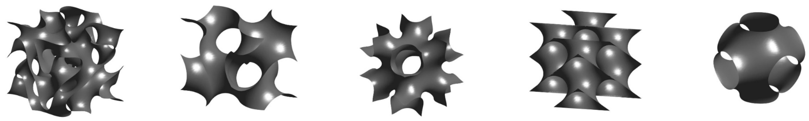
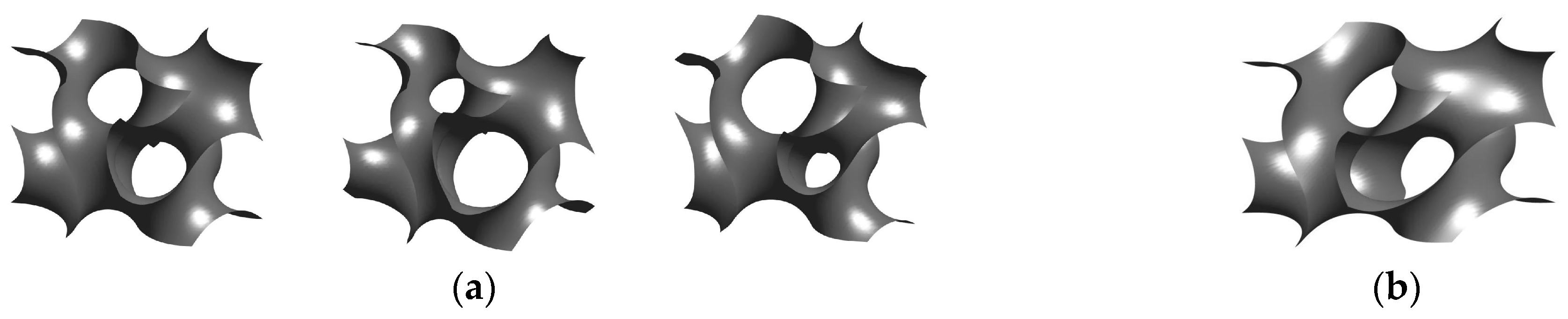
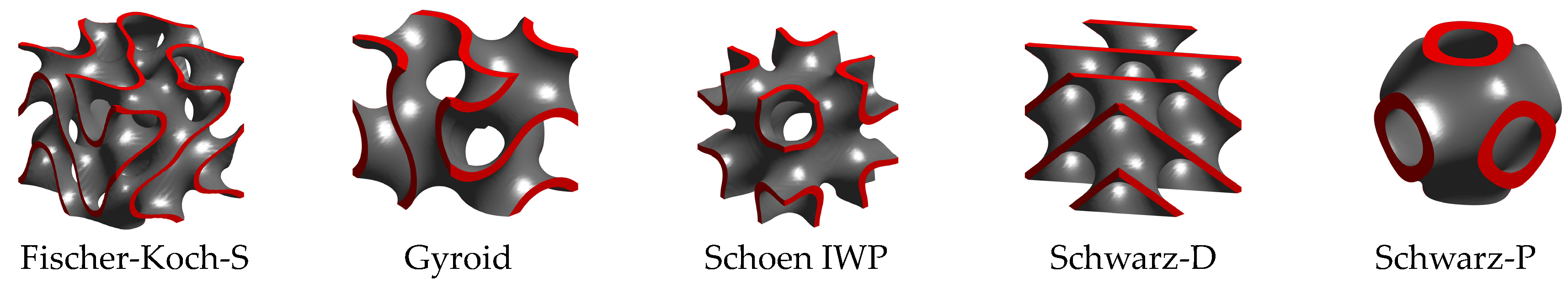
2.1. TPMS-Based Structures

TPMSs are smooth and continuous 3D surfaces with zero mean curvature at every point, dividing space into two distinct regions without self-intersection. Figure 1 provides a visualization of some of the most frequently studied TPMS surfaces [19,20,21,22]. Through the use of 3D-printing technologies, they have reached practical implementation.
Their topology and surface can be described mathematically by an implicit function consisting of trigonometric terms, referred to as a level-set equation [25], allowing for various designs. In this work, five different TPMS structures were investigated, whose designs are described by Equations (1)–(5):
F Fischer Koch S x , y , z = cos ( 2 k x x ) sin ( k y y ) cos ( k z z ) + cos ( k x x ) cos ( 2 k y y ) sin k z z + sin k x x cos ( k y y ) cos 2 k z z = t
F Gyroid x , y , z = cos ( k x x ) sin ( k y y ) + cos ( k y y ) sin ( k z z ) + cos ( k z z ) sin k x x = t
F Schoen   IWP x , y , z = 2 cos k x x cos k y y + cos k y y cos k z z + cos k z z cos k x x [ cos 2 k x x + cos 2 k y y + cos 2 k z z ] = t
F Schwarz D x , y , z = sin ( k x x ) sin ( k y y ) sin k z z + sin ( k x x ) cos k y y cos k z z + cos ( k x x ) sin ( k y y ) cos k z z + cos ( k x x ) cos ( k y y ) sin k z z = t
F S c h w a r z P x , y , z = cos ( k x x ) + cos ( k y y ) + cos k z z = t
In these formulas, x , y , and z represent the Cartesian coordinates; k i = 2 π / L i , where L i is the unit cell length in each principal direction. The constant t is the level-set parameter that controls the ratio of the two volumes that are separated by the surface. For t = 0, the iso-surface divides the space into two subdomains of equal volume. Accordingly, asymmetrical channel sizes arise by solving F x , y , z for t 0 . Figure 2a provides an example of how the level surface of a cubic gyroid structure changes when the value of t is modified.
Another way of introducing asymmetry into TPMS structures is through the distortion (e.g., stretching) of the primary cubic cells. In Figure 2b, a distorted gyroid structure for a level-set parameter of t = 0 is illustrated by a cuboidal unit cell with a quadratic base area and a length-to-width ratio ( B ) greater than 1, resulting in a noncubic structure.
In order to generate solid domains based on the level-set equations given in Equations (1)–(5), the sheet approach is used [25,26]. This approach can be implemented by evaluating the level-set equation at ± t . Consequently, two surfaces are generated at level-set parameters that have the same magnitude but opposite signs. Both surfaces are equally distanced from a hypothetical surface (the reference surface), which is defined by the mean value of the two level-set parameters. This value is termed t r e f in this work and takes a value of 0 when evaluating the level-set equation at ± t . Finally, the thickened TPMS surface corresponds to the solid domain bounded by these two level-set surfaces, and the space between these two adjacent iso-surfaces becomes the structure’s wall thickness [26]. Furthermore, the thickened TPMS structure can also be created from a hypothetical surface evaluated at a reference level-set parameter t r e f 0 by evaluating the level-set equation symmetrically in terms of this reference condition [27]. Figure 3 shows the five different and thickened TPMS structures used for investigation, with an example provided for a void fraction of 80%, which is defined as the ratio of the void volume to the total volume of the unit cell. The specific surface is computed by dividing the area of the reference surface by the total volume of the unit cell.
It should be noted that for each TPMS structure, there is a range of the reference level-set parameter ( t r e f   t 1 , t 2 , see Table 1) within which the surfaces and thus the solid and void domains are connected (no discontinuities).
Based on Equations (1)–(5), the TPMS geometries were generated using a MATLAB script, which transferred the triangulated surfaces to ANSYS software 2023 R1, where the geometries were thickened. The approach used for the thickening process is described in detail in [28].

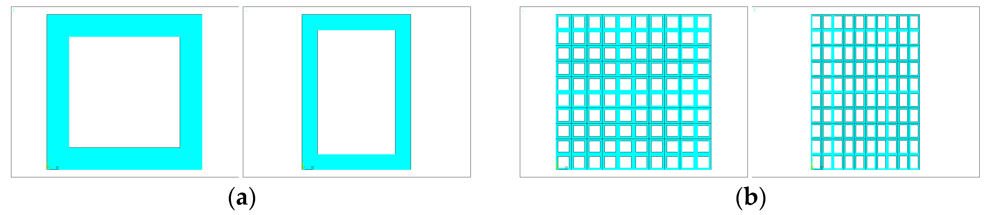
2.2. Honeycomb Structures

Honeycomb structures can be mathematically described by the geometric shape of their unit cells and their spatial arrangement and outer shape. In many cases, they consist of regularly and periodically arranged unit cells. In this work, honeycomb structures with a rectangular outer shape were considered, in which the cells were arranged in uniform rows (nonstaggered structures) and featured a homogeneous wall thickness and an inner rectangular shape (see Figure 4). Such unit cells could be easily represented using a 2D approach by specifying the wall thickness and channel dimensions. The specific surface was referenced to the symmetry plane.

3. Methodology and Modeling
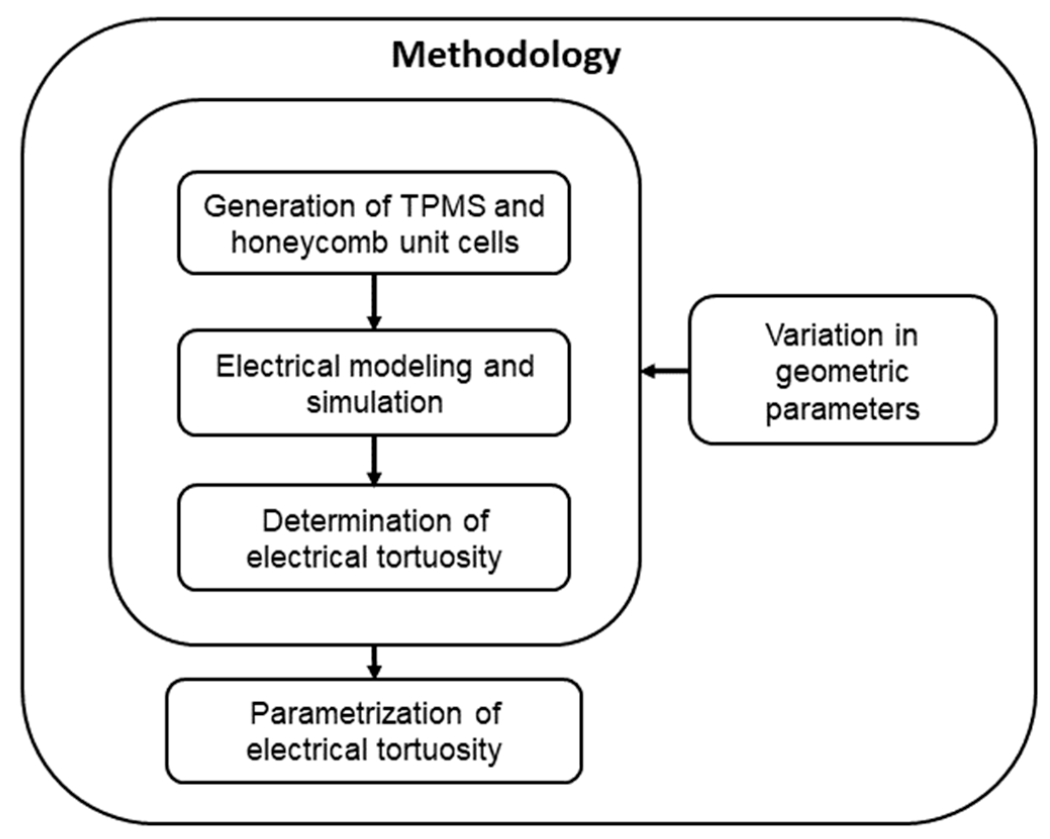
3.1. Methodology

The methodology for deriving a parameterized correlation for electrical tortuosity depending on central geometric parameters is depicted in Figure 5. Beginning with the generation of representative unit cells (smallest repeating structure of an overall geometric lattice) using a MATLAB (R2020a, MathWorks) script, these structures were meshed using ANSYS software (Ansys, Inc., Canonsburg PA, USA). Subsequently, the electrical boundary conditions (see Section 3.2) were specified, and the effective electric resistance of the porous structure and of the appropriate solid body was calculated. Considering the most basic definition of tortuosity, which is the ratio of the actual tortuous path length to the straight-line length in porous media [8,9], this concept was applied to the electrical resistance of porous structures. Hence, the electrical tortuosity τ e l was determined by the ratio of the resistance of the porous structure R e f f to that of the appropriate solid body R according to Equation (6), thus being independent of material properties. Here, L is the length and A is the cross-sectional area of the unit cell, and ρ e l is the electrical resistivity of the solid material.
R e f f R = ρ e l τ e l L A ρ e l L A = τ e l
Various geometric configurations were investigated by varying central geometric parameters individually. For honeycomb structures, the void fraction ε , the length of the unit cell L , and the aspect ratio B of the unit cells were varied. In addition to these three parameters, the level-set parameter t r e f was also varied for TPMS structures. Subsequently, the electrical tortuosity was parameterized using suitable formulations.

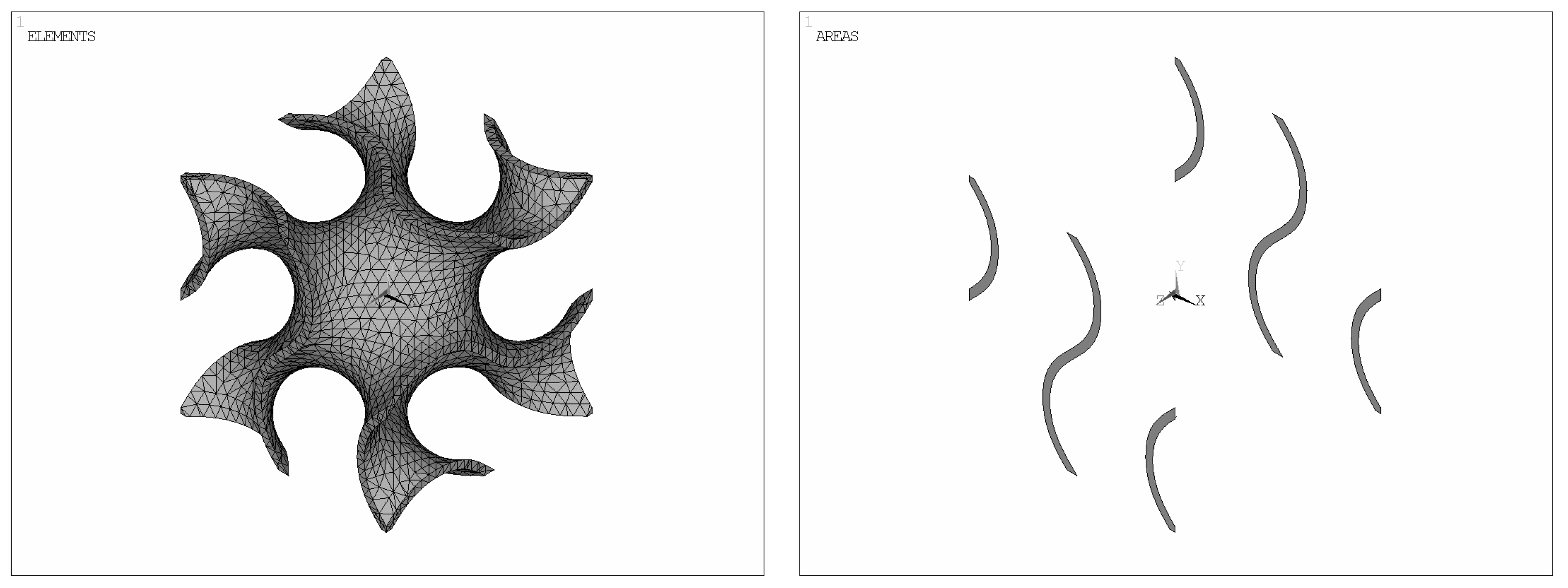
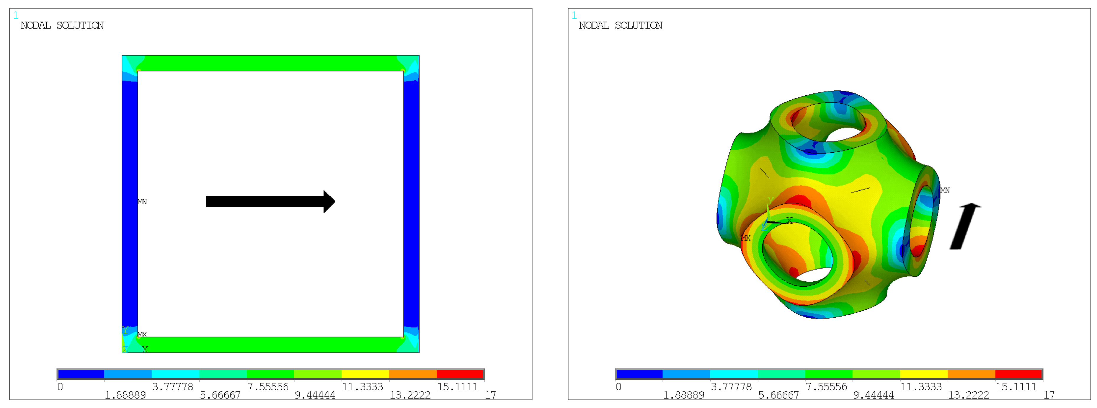
3.2. Electrical Modeling

The electrical simulations were carried out using the finite element software ANSYS, setting the following boundary conditions: a constant voltage was applied to one side of the structure (inlet), while a constant current density was specified on the other side (outlet). The resulting voltage difference U between the inlet and outlet varied with the effective electrical resistance of the structure. This effective electric resistance R e f f was calculated using Ohm’s law by dividing the voltage difference U by the current I . The resistance R of the appropriate solid body was obtained by taking the length L and cross-sectional area A of the unit cell and the electrical resistivity ρ e l . These two values were used with Equation (6) to calculate the electrical tortuosity.
Appropriate mesh sizes were determined through a convergence analysis until negligible variance in electrical tortuosity was obtained, resulting in a minimum of 50,000 elements for the 3D-case (TPMS) and 5000 elements for the 2D-case (honeycomb).
As part of the grid study, calculations were performed for structures ranging from 1 × 1 × 1 to 4 × 4 × 4 unit cells. It was observed that multiple aligned unit cells did not result in any deviation in electrical tortuosity compared to the 1 × 1 × 1 unit cells. For this reason, the simulation domain consisted of single unit cells (1 × 1 × 1). Figure 6 illustrates a meshed gyroid structure and the inlet and outlet surfaces for defining the boundaries conditions within the simulation domain.

4. Results and Discussions

This section is divided into five subsections. The first subsection presents the results of the effects of specific surface and void fraction on electrical tortuosity. The second subsection covers the electrical tortuosity of isotropic TPMS and honeycomb structures, while the third subsection examines variations in electrical tortuosity for varying level-set parameters t r e f (only for TPMS). The fourth subsection discusses the results for anisotropic TPMS and honeycomb structures. The last subsection compares the results with those in the available literature and describes the limitations of and possible difficulties facing the proposed models.

4.1. Effect of Specific Surface on Electrical Tortuosity for TPMS and Honeycomb Structures

To investigate the influence of the specific surface on electrical tortuosity, the wall thickness s W and unit cell size L were varied for the honeycomb and TPMS structures. Depending on the wall thickness and the size of the unit cell, the specific surfaces and void fractions differ. The findings show that the electrical tortuosity of both honeycomb and TPMS structures does not change with the specific surface when the void fraction is kept constant. This is illustrated for honeycomb structures in Figure 7 and can be explained by the fact that electrical tortuosity, as a dimensionless parameter, is scale-independent—like the void fraction—and captures only the fundamental properties of a structure, irrespective of actual cell size.

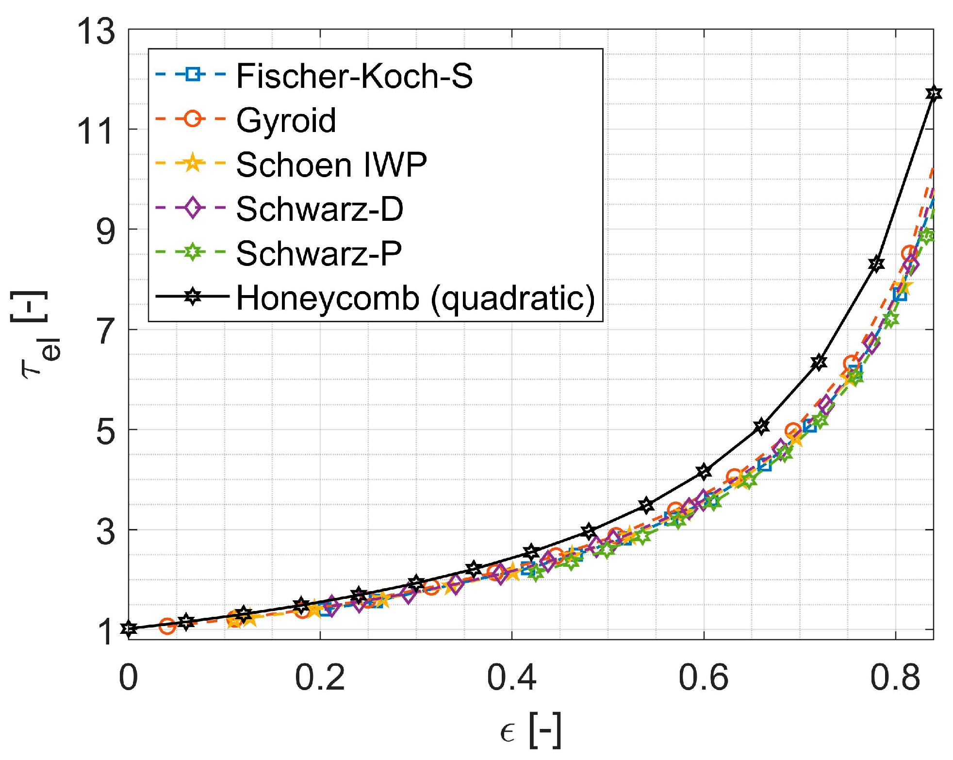
4.2. Effect of Void Fraction on Electrical Tortuosity for Isotropic TPMS and Honeycomb Structures

Figure 8 shows the electrical tortuosity as a function of the void fraction (varied parameters: wall thickness and unit cell length) for the different TPMS structures and honeycomb structures with quadratic channels, including curve fit data. The data indicate that there is a power-law relationship between electrical tortuosity τ e l and void fraction ε .
Generally, the electrical tortuosity rises with an increased void fraction as there is less solid volume available for the conduction of current. In addition, it can be observed that the electrical tortuosities of the investigated TPMS structures are very close to each other, with the gyroid structure exhibiting the highest and the Schwarz-P structure showing the lowest values. These results are consistent with the experimental findings of Catchpole-Smith et al. [22].
Furthermore, it can be seen that the electrical tortuosities of the cubical honeycomb structures are approximately 10–20% larger than those of the TPMS structures due to the considerable ‘dead volume’. This can be explained by the fact that in the highly interconnected porous TPMS structures, nearly all the solid volume is used to conduct electric current. In contrast, in the honeycomb structures, a significant solid volume fraction is not used for current transport (referred to as ‘dead volume’), which increases the actual electric resistance. This unused solid volume is mainly located perpendicular to the direction of current flow (see Figure 9).
The parameterized correlations for electrical tortuosity for the isotropic TPMS and honeycomb structures can be found in Section 4.3 (Table 2).

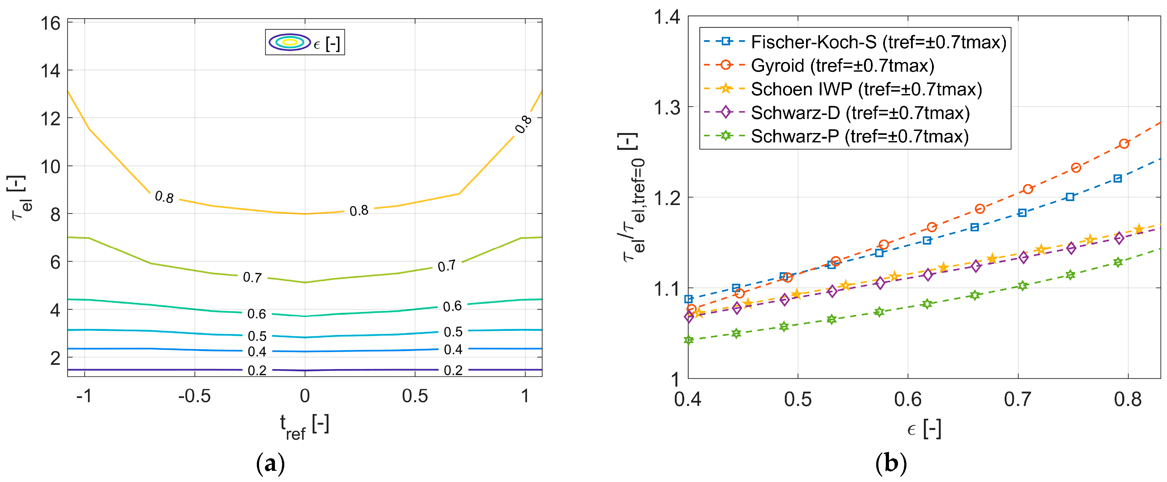
4.3. Effect of Level-Set Parameter on Electrical Tortuosity for Isotropic TPMS Structures

So far, only the influence of the void fraction on electrical tortuosity for isotropic cells with t r e f = 0 was demonstrated. Now, the level-set parameter t r e f was also varied for isotropic TPMS structures. Due to the fact that defects in the spatial structure (discontinuities) occur when approaching the critical level-set parameters, the level-set parameter of the respective TPMS structure was varied within a maximum range of up to 70% of the maximum possible values ( t 1 , t 2 ) , as shown in Table 1.
The effect of the level-set parameter on electrical tortuosity, depending on the void fraction, is shown for a Gyroid structure in Figure 10a. It is evident that level-set parameters t r e f with the same magnitude but opposite signs lead to an identical increase in electrical tortuosity, as congruent surfaces are generated. Furthermore, the greater the magnitude, the larger the increase in electrical tortuosity. These fundamental relationships apply to all the TPMS structures investigated and can be explained by the fact that for t r e f 0 (with t r e f = 0 representing symmetrical channel sizes), there is an increase in the asymmetry within the structure. As a result, there is solid volume that is actually not used for current transport (‘dead volume’), thereby increasing the effective electrical resistance.
However, in contrast to symmetrical unit cells, the relative change in the electrical tortuosity varies among the different TPMS structures, as shown in Figure 10b for a value of t r e f = ±   0.7 t m a x , where t m a x t 1 , t 2 . Thus, it appears that by introducing asymmetry, depending on the TPMS structure, the electrical tortuosity can be increased by a factor of approximately 5–15% for an example void fraction range of 40–60%.
Finally, the parameterized correlations for the electrical tortuosity for the investigated honeycomb and TPMS structures (see Table 2) were derived using a power function, as this approach accurately depicted the general relationships. Specifically, for void fractions close to zero (representing a solid body), the electrical tortuosity approaches one (by definition), while for void fractions close to one, it tends toward infinity. The correlations are valid for void fractions ε < 0.95 and level-set parameters in the range of t r e f ±   0.7 t m a x , where t m a x t 1 , t 2 for TPMS structures. The quadratic term for the level-set parameter accounts for the fact that identical values for electrical tortuosity were obtained for both negative and positive values of the level-set parameter (as congruent surfaces are generated).
Table 2. Curve fit data of electrical tortuosity for different TPMS structures as a function of void fraction ε and level-set parameter t r e f and for honeycomb structures with quadratic channels and related errors.
Geometric
Structure
τ e l = 1 + a 0 1 ε a 1 + a 2 t r e f 2 1 Mean ErrorMaximum Error
Fischer-Koch-S a 0 = 1.8331 ,     a 1 = 0.9454 ,     a 2 = 0.4256 3.0%6.6%
Gyroid a 0 = 1.9841 ,     a 1 = 0.9318 ,     a 2 = 0.1277 3.3%8.2%
Schoen IWP a 0 = 1.8665 ,     a 1 = 0.9369 ,     a 2 = 0.0197 3.3%11.0%
Schwarz-D a 0 = 1.9230 ,     a 1 = 0.9284 ,     a 2 = 0.1895 2.8%8.8%
Schwarz-P a 0 = 1.7099 ,     a 1 = 0.9659 ,   a 2 = 0.1243 2.0%5.5%
Honeycomb (quadratic) a 0 = 2.3449 , a 1 = 0.9353 , a 2 = 0 0.5%1.2%

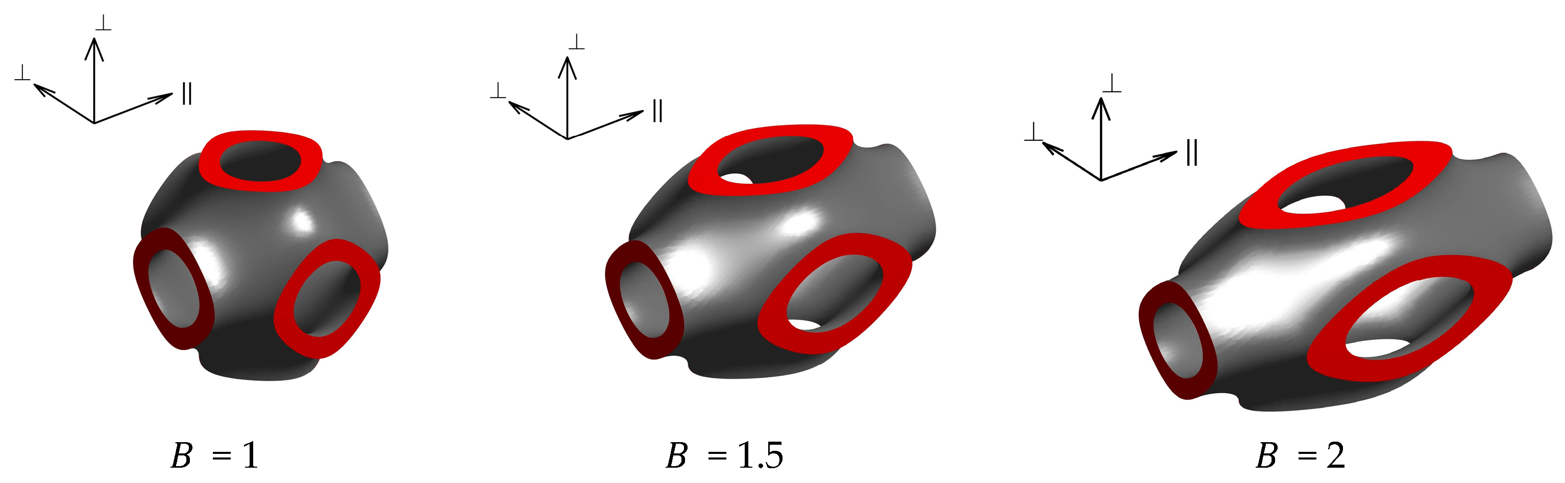
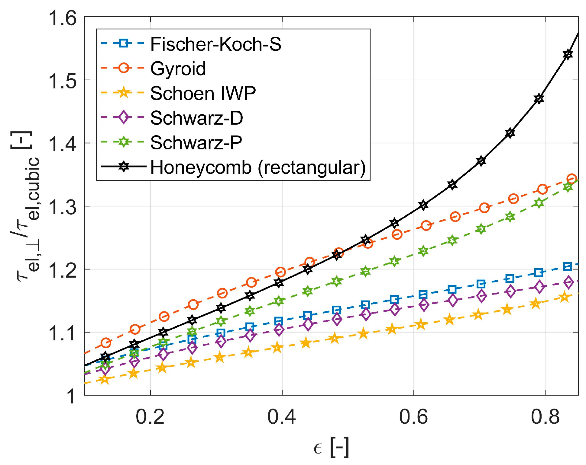
4.4. Effect of Anisotropy on Electrical Tortuosity for TPMS and Honeycomb Structures

Up to this point, electrical tortuosity was investigated exclusively for isotropic TPMS and honeycomb structures, depending on the void fraction ε (Section 4.2) and the level-set parameter t r e f (Section 4.3). Another way to influence electrical tortuosity is through the distortion of the primary cubic unit cells, which introduces asymmetry into the structures. To quantify the effect of distortion on electrical tortuosity, the aspect ratio B of a cuboidal unit cell with a quadratic base was varied within 1 ≤ B ≤ 2, where B represents the length of the cuboid relative to the width of its quadratic base, alongside the void fraction ε (varied parameter: wall thickness). For the TPMS structures, only level-set parameters t r e f = 0 were considered. Figure 11 illustrates the cuboidal unit cells of a Schwarz-P structure for different aspect ratios B , each with the same void fraction. By increasing the aspect ratio B of the unit cells with a constant void fraction, the primarily cubic unit cell ( B = 1) is elongated in one spatial direction (the ‘ -direction’) and compressed in the two spatial directions perpendicular to it (the ‘ -direction’). This is why noncubic cell geometries exhibit direction-dependent (anisotropic) electrical tortuosities.
When considering cuboidal unit cells with a quadratic base, the electrical tortuosities orthogonal to the direction of stretching are identical because these two spatial directions have the same aspect ratio relative to the direction of stretching. However, they generally differ from the electrical tortuosities parallel to the direction of stretching. This is illustrated in Figure 12, where the electrical tortuosity orthogonal ( τ e l , ) and parallel ( τ e l , ) to the direction of stretching is plotted as a function of the aspect ratio B and the void fraction ε for a Schwarz-P structure. In general, it can be concluded that the greater the geometric distortion, the larger the increase in electrical tortuosity orthogonal to the direction of stretching as more ‘dead volume’ is generated (Figure 12a). In contrast, the electrical tortuosity parallel to the direction of stretching decreases with increasing aspect ratio B (Figure 12b), which can be explained by the decreasing intricacy of the structure as a result of the elongation.
In general, similar dependencies on distortion were observed for all the structures examined. To quantify the effect of anisotropy on electrical tortuosity, the relative increase orthogonal to the direction of stretching (compared to cubic cell geometries) is shown in Figure 13 for an aspect ratio of B = 2. It can be seen that the electrical tortuosity increases by approximately 8–25%, depending on the TPMS structure, for a void fraction range of 40–60%. For honeycomb structures, increases of up to 30% are possible within this range.
The results for the TPMS structures show that for same void fractions, even relatively moderate aspect ratios can have a stronger influence on electrical tortuosity than variations in the level-set parameter t r e f . The parameterized correlations for electrical tortuosity orthogonal ( τ e l , ) and parallel ( τ e l , ) to the direction of stretching, depending on the void fraction ε and the aspect ratio B , are summarized in Table 3. These correlations are valid for 1 ≤ B ≤ 2.
In summary, the void fraction can be stated as the factor defining electrical tortuosity, with honeycomb structures generally achieving slightly higher electrical tortuosities than TPMS structures at the same void fraction. With regard to the influence of distortion on electrical tortuosity, it was observed that the electrical tortuosity of TPMS structures can be modified to an almost similar extent as for honeycomb structures.
At this point, it should be emphasized that the formation of zones with low current flow (‘dead volume’) contributes to an increase in the effective electrical resistance of the porous structure, potentially leading to local hotspots. Nevertheless, additional investigations of the temperature distribution showed that this is noncritical due to the high thermal conductivities ( λ > 15 W/mK) of metallic alloys or electroconductive ceramic materials commonly used for P2H applications.

4.5. Comparison to the Literature and Limitations

Comparisons with the work of Abueidda et al. [20] and Sauermoser-Yri et al. [21] were made to verify our simulation results and to demonstrate the extended range of validity for our derived equations. This is shown for a Gyroid structure in Figure 14, where the good agreement of our results is seen as well as the enhanced extent of validity.
The results of this study in the form of parameterized electrical tortuosities are valid for direct current applications, as alternating current effects (such as the skin effect) were not modeled. Additionally, the derived equations serve as a preliminary design tool, allowing for computationally efficient and extensive design studies without requiring an exact representation of the structures to identify feasible and favored solutions. Consequently, the local structures and the phenomena occurring within them (such as hotspots) are not captured.

5. Conclusions

The key requirements for P2H systems include high thermal efficiency and suitable electrical resistivity to meet application-specific electrical needs. When designing P2H systems, materials and electrical boundary conditions are often limited by application-specific requirements, whereas geometric structures provide a high degree of freedom.
While thermal design calculations are often straightforward due to various available Nusselt and pressure loss correlations, there is a lack of simplified design pathways for electrical design calculations, especially for porous structures. Since detailed modeling involves substantial computational effort, this work employed electrical tortuosity to capture and correlate geometric-dependent impacts on effective electrical resistance in a compact way. Through this approach, the modeling of extensive, finely resolved structures can be omitted, thereby providing a basis for simplified and computationally efficient electrical design calculations for P2H systems. Honeycomb and triply periodic minimal surface (TPMS)-based structures were selected for this purpose, as they are characterized by high specific surfaces, allowing for high total heat transfer coefficients.
Compared to the literature, this work investigated the influence of geometric structure on effective electrical resistance across a broad range of individually varied geometric parameters for the first time, including void fraction (across its full range), specific surface, aspect ratio, and level-set parameter (the last of which applies only to TPMS structures). For this purpose, numerous electrical simulations were carried out using finite element software and a unit cell approach to determine the effective electrical resistance.
The findings revealed that the effective electrical resistance of both TPMS and honeycomb structures can be adjusted by their geometric configuration to varying degrees. The electrical tortuosities of the investigated TPMS structures were nearly identical, while the honeycomb structures exhibited slightly higher values. This can be attributed to the formation of zones with low current flow (‘dead volume’), which reduces the solid volume available for current conduction and increases the effective electrical resistance of the porous structure. Generally, electrical tortuosity is mainly a function of void fraction and does not change with the specific surface when the void fraction is kept constant. By varying the aspect ratio or the level-set parameter (only for TPMS structures), the electrical tortuosity can be increased as the introduced asymmetry generates more ‘dead volume’.
Finally, the correlations for electrical tortuosity based on central geometric parameters were derived for the first time, with an average error below 5% and a maximum error below 11%. The contribution of this paper provides users, for the first time, a basis for simplified preliminary electrical design calculations for P2H systems. The parameterized equations presented here are, for the first time, applicable over a wide range of parameters, enabling a computationally efficient investigation of large-scale structures without the need to model the entire structure in detail. This enables users to select suitable geometric structures holistically, considering both application-specific needs and thermal and electrical requirements. Future work will focus on the experimental validation of the simulation results.

Author Contributions

Conceptualization, T.O.; methodology, T.O. and V.D.; software, T.O.; writing—original draft preparation, T.O.; writing—review and editing, V.D.; visualization, T.O.; supervision, V.D. All authors have read and agreed to the published version of the manuscript.

Funding

This research received no external funding.

Data Availability Statement

Data are contained within this article.

Conflicts of Interest

The authors declare no conflicts of interest.

References

  1. Lupi, S. Fundamentals of Electroheat: Electrical Technologies for Process Heating, 1st ed.; Springer: Cham, Switzerland, 2017. [Google Scholar]
  2. Belik, S. Techno-economic evaluation of a Brayton battery configuration with power-to-heat extension. J. Energy Storage 2023, 68, 107416. [Google Scholar] [CrossRef]
  3. Dreißigacker, V. Power-to-heat in adiabatic compressed air energy storage power plants for cost reduction and increased flexibility. Heat Mass Transf. 2017, 54, 955–962. [Google Scholar] [CrossRef]
  4. Benato, A. Performance and cost evaluation of an innovative Pumped Thermal Electricity Storage power system. Energy 2017, 138, 419–436. [Google Scholar] [CrossRef]
  5. Knote, T. E-Bus-Standard: “Ansätze zur Standardisierung und Zielkosten für Elektrobusse”; Fraunhofer-Institut für Verkehrs- und Infrastruktursysteme (IVI): Dresden, Germany, 2017. [Google Scholar] [CrossRef]
  6. Dreißigacker, V.; Hofer, L. High-Performance Solid Medium Thermal Energy Storage System for Heat Supply in Battery Electric Vehicles: Proof of Concept and Experimental Testing. Appl. Sci. 2022, 12, 10943. [Google Scholar] [CrossRef]
  7. Dreißigacker, V. Solid Media Thermal Energy Storage System for Heating Electric Vehicles: Advanced Concept for Highest Thermal Storage Densities. Appl. Sci. 2020, 10, 8027. [Google Scholar] [CrossRef]
  8. Ghanbarian, B.; Hunt, A.G.; Ewing, R.P.; Sahimi, M. Tortuosity in Porous Media: A Critical Review. Soil Sci. Soc. Am. J. 2013, 77, 1461–1477. [Google Scholar] [CrossRef]
  9. Clennell, M.B. Tortuosity: A guide through the maze. Geol. Soc. Lond. Spec. Publ. 1997, 122, 299–344. [Google Scholar] [CrossRef]
  10. Liu, J.; Cheng, D.; Oo, K.; Pan, W.; McCrimmon, T.-L.; Bai, S. Optimization of Triply Periodic Minimal Surface Heat Exchanger to Achieve Compactness, High Efficiency, and Low-Pressure Drop. Energies 2024, 17, 5141. [Google Scholar] [CrossRef]
  11. Yeranee, K.; Rao, Y. A Review of Recent Investigations on Flow and Heat Transfer Enhancement in Cooling Channels Embedded with Triply Periodic Minimal Surfaces (TPMS). Energies 2022, 15, 8994. [Google Scholar] [CrossRef]
  12. Peng, H.; Gao, F.; Hu, W. Design, Modeling and Characterization of Triply Periodic Minimal Surface Heat Exchangers with Additive Manufacturing. In Proceedings of the Solid Freeform Fabrication, Austin, TX, USA, 12–14 August 2019. [Google Scholar]
  13. Li, W.; Yu, G.; Yu, Z. Bioinspired heat exchangers based on triply periodic minimal surfaces for supercritical CO2 cycles. Appl. Therm. Eng. 2020, 179, 115686. [Google Scholar] [CrossRef]
  14. Iyer, J.; Moore, T.; Nguyen, D.; Roy, P.; Stolaroff, J. Heat transfer and pressure drop characteristics of heat exchangers based on triply periodic minimal and periodic nodal surfaces. Appl. Therm. Eng. 2022, 209, 118192. [Google Scholar] [CrossRef]
  15. Feng, J.; Fu, J.; Yao, X.; He, Y. Triply periodic minimal surface (TPMS) porous structures: From multi-scale design, precise additive manufacturing to multidisciplinary applications. Int. J. Extrem. Manuf. 2022, 4, 022001. [Google Scholar] [CrossRef]
  16. Kladovasilakis, N.; Tsongas, K.; Tzetzis, D. Mechanical and FEA-Assisted Characterization of Fused Filament Fabricated Triply Periodic Minimal Surface Structures. J. Compos. Sci. 2021, 5, 58. [Google Scholar] [CrossRef]
  17. Peng, C.; Marzocca, P.; Tran, P. Triply periodic minimal surfaces based honeycomb structures with tuneable mechanical responses. Virtual Phys. Prototyp. 2022, 18, e2125879. [Google Scholar] [CrossRef]
  18. Pan, C.; Han, Y.; Lu, J. Design and Optimization of Lattice Structures: A Review. Appl. Sci. 2020, 10, 6374. [Google Scholar] [CrossRef]
  19. Ye, X.-C.; Lin, X.-C.; Xiong, J.-Y.; Wu, H.-H.; Zhao, G.-W.; Fang, D. Electrical properties of 3D printed graphite cellular lattice structures with triply periodic minimal surface architectures. Mater. Res. Express 2019, 6, 125609. [Google Scholar] [CrossRef]
  20. Abueidda, D.W.; Abu Al-Rub, R.K.; Dalaq, A.S.; Lee, D.-W.; Khan, K.A.; Jasiuk, I. Effective conductivities and elastic moduli of novel foams with triply periodic minimal surfaces. Mech. Mater. 2016, 95, 102–115. [Google Scholar] [CrossRef]
  21. Sauermoser-Yri, M.; Veldurthi, N.; Wölfle, C.H.; Svartvatn, P.J.; Flo Hoem, S.O.; Lid, M.J.; Bock, R.; Palko, J.W.; Torgersen, J. On the porosity-dependent permeability and conductivity of triply periodic minimal surface based porous media. J. Mater. Res. Technol. 2023, 27, 585–599. [Google Scholar] [CrossRef]
  22. Catchpole-Smith, S.; Sélo, R.R.J.; Davis, A.W.; Ashcroft, I.A.; Tuck, C.J.; Clare, A. Thermal conductivity of TPMS lattice structures manufactured via laser powder bed fusion. Addit Manuf 2019, 30, 100846. [Google Scholar] [CrossRef]
  23. Pichler, M.; Haddadi, B.; Jordan, C.; Harasek, M. Modeling the effective thermal conductivity of hollow bricks at high temperatures. Constr. Build. Mater. 2021, 309, 125066. [Google Scholar] [CrossRef]
  24. Wang, E.; Shi, Z.; Chen, M.; Tang, S.; Zhang, X.; Zhang, W. Investigation of effective thermal conductivity of SiC foam ceramics with various pore densities. Open Phys. 2022, 20, 58–65. [Google Scholar] [CrossRef]
  25. Lambert, C.A.; Radzilowski, L.H.; Thomas, E.L. Triply periodic level surfaces as models for cubic tricontinuous block copolymer morphologies. Philos. Trans. R. Soc. London. Ser. A Math. Phys. Eng. Sci. 1996, 354, 2009–2023. [Google Scholar] [CrossRef]
  26. Al-Ketan, O.; Abu Al-Rub, R.K. MSLattice: A free software for generating uniform and graded lattices based on triply periodic minimal surfaces. Mater. Des. Process. Commun. 2020, 3, e205. [Google Scholar] [CrossRef]
  27. Al-Ketan, O.; Abu Al-Rub, R.K. Multifunctional Mechanical Metamaterials Based on Triply Periodic Minimal Surface Lattices. Adv. Eng. Mater. 2019, 21, 1900524. [Google Scholar] [CrossRef]
  28. Jin, Y.; Kong, H.; Zhou, X.; Li, G.; Du, J. Design and Characterization of Sheet-Based Gyroid Porous Structures with Bioinspired Functional Gradients. Materials 2020, 13, 3844. [Google Scholar] [CrossRef]
Figure 1. Different TPMS structures in a unit cell, from left to right: Fischer-Koch-S, Gyroid, Schoen IWP, Schwarz-D, and Schwarz-P.
Energies 17 05781 g001
Figure 2. (a) Different cubic Gyroid structures in a unit cell for different level-set parameters (from left to right: t = 0, t = 0.5 and t = −0.5); (b) noncubic unit cell of a Gyroid structure for a level-set parameter of t = 0 with an exemplary aspect ratio B = 1.5.
Energies 17 05781 g002
Figure 3. Unit cells of thickened cubic TPMS structures ( t r e f = 0 ) with a void fraction of 80% and a specific surface of 100 m2/m3.
Energies 17 05781 g003
Figure 4. (a) Unit cells with homogeneous wall thickness and quadratic and rectangular channel; (b) honeycomb structures with an outer rectangular shape, consisting of 10 × 10 unit cells having a quadratic and rectangular channel geometry.
Energies 17 05781 g004
Figure 5. Methodology for deriving parameterized electrical tortuosity.
Energies 17 05781 g005
Figure 6. Example of a meshed gyroid structure (left) and inlet and outlet surfaces for setting the boundary conditions (right).
Energies 17 05781 g006
Figure 7. Electrical tortuosity as a function of void fraction and specific surface for honeycomb structures.
Energies 17 05781 g007
Figure 8. Electrical tortuosity as a function of void fraction for different TPMS structures with reference level-set parameter t r e f = 0 in comparison to a honeycomb with quadratic channels.
Energies 17 05781 g008
Figure 9. Electric current density distribution for a honeycomb with quadratic channels and a Schwarz-P structure for a void fraction ε = 0.8; red is the highest and blue is the lowest current density. The arrow indicates the direction of the current flow.
Energies 17 05781 g009
Figure 10. (a) Electrical tortuosity as a function of the level-set parameter t r e f and void fraction ε illustrated for a Gyroid structure; (b) increase in electrical tortuosity for a level-set parameter of t r e f = ±   0.7 t m a x , related to the base surface ( t r e f = 0) for all investigated TPMS structures.
Energies 17 05781 g010
Figure 11. Cuboidal unit cells with a quadratic base for a Schwarz-P structure ( t r e f = 0 ) with a void fraction of 80% and different aspect ratios B ; the primarily cubic unit cell ( B = 1) is elongated in the ‘∥-direction’ and compressed in the two spatial directions perpendicular to it (the ‘⊥-direction’).
Energies 17 05781 g011
Figure 12. Electrical tortuosity as a function of void fraction ε and the aspect ratio B for a Schwarz-P structure: (a) orthogonal to the direction of stretching; (b) parallel to the direction of stretching.
Energies 17 05781 g012
Figure 13. Electrical tortuosity orthogonal to the direction of stretching as a function of void fraction ε for an aspect ratio of B = 2 for TPMS and honeycomb structures.
Energies 17 05781 g013
Figure 14. Comparison of the electrical tortuosity as a function of the void fraction with the results of Abueidda et al. [20] and Sauermoser-Yri et al. [21].
Energies 17 05781 g014
Table 1. Critical level-set parameters t1 and t2 for different TPMS structures for connected solid phase and void phase (no discontinuities).
TPMS Structure t 1 [-] t 2 [-]
Fischer-Koch-S−0.750.75
Gyroid−1.41.4
Schoen IWP−2.992.99
Schwarz-D−0.990.99
Schwarz-P−1.01.0
Table 3. Curve fit data of electrical tortuosity for different TPMS structures ( t r e f = 0) and honeycomb structures with rectangular channels as a function of void fraction ε and the aspect ratio B and related errors.
Geometric
Structure
τ e l , = 1 + a 0 1 ε a 1 + b ( B 1 ) 1 τ e l , = 1 + a 0 ( 1 ε ) a 1 + b ( B 1 ) 1 Mean ErrorMaximum Error
Fischer-Koch-S a 0 = 1.8331 ,     a 1 = 0.9454 b = 0.1083 ,     b = 0.1479 2.6%5.6%
Gyroid a 0 = 1.9841 ,   a 1 = 0.9318 b = 0.1686 ,     b = 0.1584 4.7%9.6%
Schoen IWP a 0 = 1.8665 ,     a 1 = 0.9369 b = 0.0833 ,     b = 0.0889 3.2%4.5%
Schwarz-D a 0 = 1.9230 ,     a 1 = 0.9284 b = 0.1000 ,     b = 0.1356 2.6%4.2%
Schwarz-P a 0 = 1.7099 ,   a 1 = 0.9659 b = 0.1483 ,     b = 0.1500 3.7%8.2%
Honeycomb (rectangular) a 0 = 2.3449 ,     a 1 = 0.9353 b = 0.2070 ,     b = 0.1396 3.7%10.8%
Disclaimer/Publisher’s Note: The statements, opinions and data contained in all publications are solely those of the individual author(s) and contributor(s) and not of MDPI and/or the editor(s). MDPI and/or the editor(s) disclaim responsibility for any injury to people or property resulting from any ideas, methods, instructions or products referred to in the content.

